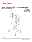
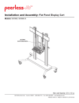
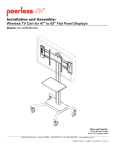
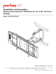
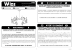
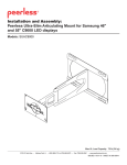
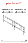
1
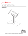
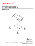
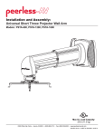
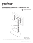
Installation and Assembly: 32" - 65" Flat Panel TV Cart
Models: SR1M, SR560M
This product is UL Listed. It must be
installed by a qualified professional
installer.
Max UL Load Capacity:
150 lb (68 kg) screen
50 lb (22.7 kg) per shelf
2300 White Oak Circle • Aurora, Il 60502 • (800) 865-2112 • Fax: (800) 359-6500 • www.peerlessmounts.com
ISSUED: 01-10-07 SHEET #: 009-9039-15 05-23-12
NOTE: Read entire instruction sheet before you start installation and assembly.
WARNING
• Do not begin to install your Peerless product until you have read and understood the instructions and warnings
contained in this Installation Sheet. If you have any questions regarding any of the instructions or warnings, for US
customers please call Peerless customer care at 1-800-865-2112, for all international customers, please contact
your local distributor.
• This product should only be installed by someone of good mechanical aptitude, and fully understands
these instructions.
• Never exceed the Maximum UL Load Capacity on page 1.
• Always use an assistant or mechanical lifting equipment to safely lift and position equipment.
• Tighten screws firmly, but do not overtighten. Overtightening can damage the items, greatly reducing their holding
power.
• The cart is not affixed or secured to the floor, and may therefore tip over and/or fall if screen and/or stand is shaken
or hit. Always monitor children and do not let children play alone around stand as they could get hurt by a falling
screen. Not recommended for use in areas with heavy traffic.
Tools Needed for Assembly
• level
• phillips screwdriver
Table of Contents
Parts List............................................................................................................................................................................ 3, 4
Assembling Cart .....................................................................................................................................................................5
Attaching Universal Adapter Plate or Dedicated Adapter Plate ........................................................................................... 10
Installing Adapter Brackets ..................................................................................................................................................11
Cord Management ............................................................................................................................................................... 13
2 of 13
ISSUED: 01-10-07 SHEET #: 009-9039-15 05-23-12
Before you begin, make sure all parts shown are included with your product.
Parts may appear slightly different than illustrated.
Parts List
Description
screen mount bracket
A
hook plate
B
shelf support
C
base
D
universal plate
E
adapter bracket
F
upright
G
top cover
H
1/4-20 x 12mm decorative screw
I
1/4-20mm nut
J
L 3/8-16 x 2.5" socket screw
M 7/32" allen wrench
N 4 mm allen wrench
O 8/32 nylock nut
P shelf pan
Q 6 mm allen wrench
R left leg
S right leg
T wheel caster
U wheel caster/brake
V joint connector nut
W 3/8-16 x 1.5" screw bolt
X M10 x .402 ID lock washer
Z 3/16 allen wrench
AA M5 x 12 mm socket pin screw
BB M5 x 25 mm socket pin screw
CC M6 x 12 mm socket pin screw
DD M6 x 25 mm socket pin screw
EE M8 x 12 mm socket pin screw
FF M8 x 25 mm socket pin screw
GG M5/M4/M6 washer
HH spacer
II M10 x 15 mm socket screw
Qty.
1
1
1
1
1
2
1
1
14
10
3
1
1
6
1
1
1
1
2
2
4
4
3
1
4
4
4
4
4
4
4
4
4
3 of 13
SR1M
Part Number
201-1156
201-1157
201-1158
009-1223
N/A
N/A
580-1180
590-1210
520-2325
530-1050
520-9550
560-9715
560-9646
530-1038
009-1225
560-9716
009-1296
009-1295
600-0044
600-0045
530-1037
520-1329
540-9424
560-0071
N/A
N/A
N/A
N/A
N/A
N/A
N/A
N/A
520-9262
SR560M
Part Number
201-1156
201-1157
201-1158
009-1223
201-1110
201-1510
580-1180
590-1210
520-2325
530-1050
520-9550
560-9715
560-9646
530-1038
009-1225
560-9716
009-1296
009-1295
600-0044
600-0045
530-1037
520-1329
540-9424
560-0071
520-1064
520-1122
520-1150
520
1150
520-1211
520-1724
520-1101
580-1398
540-1059
520-9262
ISSUED: 01-10-07 SHEET #: 009-9039-15 05-23-12
Parts List continued
A
P
O
G
L
N
B
C
X
II
I
M
W
Q
Z
J
D
R
U
T
S
V
H
Universal Adapter Plate, Brackets and Hardware included with model SR560M only
AA
BB
CC
DD
EE
GG
HH
FF
F
E
Some parts may appear slightly different than illustrated.
4 of 13
ISSUED: 01-10-07 SHEET #: 009-9039-15 05-23-12
1
Insert right leg (S) into base housing (D) as shown in fig. 1.1. Then align holes in right leg with holes in base
housing (D). Fasten base housing to right leg using two 3/8-16 x 1.5" bolts (W) and two joint connectors (V). Tighten
using 3/16" allen wrench (Z) and 7/32" allen wrench (M) as shown in fig.1.2.
NOTE: Left and right legs can be identified by looking at the cart from the front.
Repeat for left side with left leg (R).
fig. 1.1
fig. 1.2
V
D
S
S
FRONT OF CART
W
FRONT OF LEG
2
Insert casters (U & T) into holes of support legs (R & S) and hand thread to secure. Attach casters with brake (U) to
the back of left and right support legs (R & S). Attach casters without brake (T) to front of support legs as shown.
NOTE: Lock brakes on casters to avoid sudden movements during installation.
HAND THREAD
R
S
U
HOLD WHEEL
T
5 of 13
ISSUED: 01-10-07 SHEET #: 009-9039-15 05-23-12
3
Attach upright (G) to base (D), as shown in fig 3.1 using three 3/8-16 x 2.5" socket screws (L) and M10 x .402ID
lock washers (X). Tighten screws using 7/32" allen wrench (M).
NOTE: Be sure cord management holes are in the configuration shown in fig 3.2.
fig. 3.1
fig. 3.2
G
CORD MANAGEMENT HOLES
D
X
L
4
Loosely attach four 1/4-20 x 12 mm screws (I) and 1/4-20 nuts (J) to shelf support (C).
J
I
C
6 of 13
ISSUED: 01-10-07 SHEET #: 009-9039-15 05-23-12
5
Slide shelf support (C) onto upright (G) so that 1/4-20 nuts (J) slide into slots of upright (G) as shown in figure 5.1
and detail 1. Slide shelf support to desired height, level, then tighten 1/4-20 x 12mm screws (I) using 4 mm allen
wrench (N).
NOTE: MAXIMUM OF TWO SHELVES
Max height of top shelf is 34" from base.
Max height of second shelf is 28" from base.
C
J
G
SLOT
DETAIL 1
fig. 5.1
7 of 13
ISSUED: 01-10-07 SHEET #: 009-9039-15 05-23-12
Attaching Metal Shelf
6
Attach shelf pan (P) to shelf support (C) using six 8/32 nylock nuts (O) as shown below. Use an adjustable wrench
to tighten six 8/32 nylock nuts (O).
WARNING
• This shelf is intended for use with equipment weighing
NO more than 50 lbs. (22.7 kg) that fits evenly accross
the surface of shelf pan (P). Use with other equipment
may result in instability and cause personal injury or
property damage.
P
C
O
8 of 13
ISSUED: 01-10-07 SHEET #: 009-9039-15 05-23-12
7
Loosely attach six 1/4-20 x 12 mm screws (I) and
1/4-20 nuts (J) to screen mount bracket (A).
Slide screen mount bracket (A) onto upright (G) so
that 1/4-20 nuts (J) slide into slots of upright (G) as
shown in figure 8.1 and detail 2. Slide screen mount
bracket to desired position, level, then tighten 1/4-20
x 12 mm screws (I) using 4 mm allen wrench (N).
8
A
J
J
I
G
I
SLOT
DETAIL 2
G
A
fig. 8.1
9
Snap top cover (H) onto upright (G).
10
Insert two 1/4-20 x 12 mm screws (I) into screen
mount bracket (A), leaving 3/16" of exposed thread
as shown in figure 10.1 and detail 3.
H
I
3/16"
G
A
DETAIL 3
fig. 10.1
9 of 13
ISSUED: 01-10-07 SHEET #: 009-9039-15 05-23-12
Attaching Universal Adapter Plate or Dedicated Adapter Plate
NOTE:Refer to instructions included with
Dedicated Adapter Plate for assembly to screen.
Once attached, proceed to step 11.
11
Attach Universal Plate (E) or Dedicated Adapter
Plate to hook plate (B) using four M10 x 15 mm
socket screws (II). Tighten screws using 6 mm allen
wrench (Q).
12
Attach hook plate (B) to screen mount bracket (A).
E
B
B
II
UNIVERSAL PLATE
OR
DEDICATED ADAPTER PLATE
(SOLD SEPARATELY, NOT EVALUATED BY UL)
A
II
B
13
Insert two 1/4-20 x 12 mm screws (I) into holes indicated below for desired screen orientation. Tighten all screws
using 4 mm allen wrench (N).
I
I
No Tilt
2° Backward Tilt
10 of 13
I
5° Forward Tilt
ISSUED: 01-10-07 SHEET #: 009-9039-15 05-23-12
Installing Adapter Brackets to Universal Plate
WARNING
• Tighten screws so adapter brackets are firmly attached. Do not tighten with excessive force. Overtightening can
cause stress damage to screws, greatly reducing their holding power and possibly causing screw heads to become
detached. Tighten to 40 in. • lb (4.5 N.M.) maximum torque.
• If screws don't get three complete turns in the screen inserts or if screws bottom out and bracket is still not tightly
secured, damage may occur to screen or product may fail.
NOTE: For Dedicated Adapter Plate, see step 11.
14
To prevent scratching the screen, set a cloth on a flat, level surface that will support the weight of the screen. Place
screen face side down. Refer to screen manufacturers instructions or customer service, for removing any knobs,
base, cover, or screw(s) on the back of the screen to prepare mounting. These need to be removed to allow the
adapter brackets to be attached. Select the small, medium, large or extra large screws from the baffled fastener
pack then attach adapter brackets to screen following figure 14.3 or 14.4.
NOTE: Top and bottom mounting holes must be used for attaching brackets. Verify that all holes are properly
aligned, and then tighten screws using a security allen wrench.
X
F
CENTER BRACKETS
VERTICALLY ON BACK
OF SCREEN
fig. 14.1
X
NOTE: "X" dimensions should be equal.
Notes:
MULTI-WASHER
• The number of fasteners used will vary,
depending upon the type of screen.
• Multi-washers and spacers may not be
used, depending upon the type of screen.
MEDIUM HOLE FOR M5 SCREWS
SMALL HOLE FOR M4 SCREWS
LARGE HOLE FOR M6 SCREWS
• Use the corresponding hole in the multiwasher that matches your screw size as
shown.
NOTE: For flat back screens proceed to step 14-3. For bump-out or recessed back screen skip to step 14-4
11 of 13
ISSUED: 01-10-07 SHEET #: 009-9039-15 05-23-12
For Flat Back Screen
14-3 Begin with the shortest length screw, hand thread through multi-washer and adapter bracket into screen as
shown below. Screw must make at least three full turns into the mounting hole and fit snug into place. Do not
over tighten. If screw cannot make three full turns into the screen, select a longer length screw from the baffled
fastener pack. Repeat for remaining mounting holes, level brackets and tighten screws.
NOTE: Spacers may not be used, depending upon the type of screen.
fig. 14.3
SCREEN
MULTI-WASHER
SCREW
ADAPTER
BRACKET (F)
If you have any questions, please call Peerless customer care at 1-800-865-2112.
For Bump-out or Recessed Back Screen
14-4
Begin with longer length screw, hand thread through multi-washer, adapter bracket and spacer in that order into
screen as shown below. Screw must make at least three full turns into the mounting hole and fit snug into place.
Do not over tighten. If screw cannot make three full turns into the screen, select a longer length screw from the
baffled fastener pack. Repeat for remaining mounting holes, level brackets and tighten screws.
fig. 14.4
SCREEN
MULTI-WASHER
SPACER
SCREW
ADAPTER
BRACKET (F)
If you have any questions, please call Peerless customer care at 1-800-865-2112.
12 of 13
ISSUED: 01-10-07 SHEET #: 009-9039-15 05-23-12
Mounting and Removing Flat Panel Screen
WARNING
• Always use an assistant or mechanical lifting equipment to safely lift and position the plasma television.
15
Hook adapter brackets (F) onto universal plate (E),
then slowly swing screen in as shown. Turn
screws of adapter plate (F) clockwise at least six
times to prevent screen from being removed as
shown in detail 4.
NOTE: Tighten using 4 mm allen wrench (N).
Screen can be adjusted horizontally if desired.
E
SCREWS
NOTE: It is important to lock screen down! To
lock the screen down, fully tighten screws to adapter
bracket as shown in detail 4.
E
F
To remove screen from mount, loosen screws,
swing screen away from mount, and lift screen off of
mount.
DETAIL 4
F
Cord Management
16
Run cords through upright (G) using cord management holes.
CORD
MANAGEMENT
G
13 of 13
ISSUED: 01-10-07 SHEET #: 009-9039-15 05-23-12
© 2012 Peerless Industries, Inc. All rights reserved.
Peerless is a registered trademark of Peerless Industries, Inc.
All other brand and product names are trademarks or registered trademarks of their respective owners.