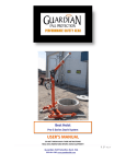
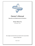
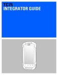
1
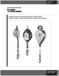
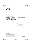
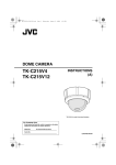
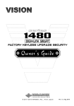
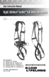
INSTRUCTIONS FOR USE
4XXX Series Skyloc™
Self Retracting Lifelines
Complies with the current ANSI Z359.1-2007 and
all applicable OSHA regulations and requirements.
Reliance Industries
P.O. Box 2046
Deer Park, TX 77536
Phone : 281-930-8000
Toll Free : 888-362-2826
Fax : 281-930-8666
Contents
DESCRIPTION
4-5
PRODUCT SPECIFICATIONS
6
APPLICATION
7
A. PURPOSE.....................................................................................................................7
1) PERSONAL FALL ARREST...................................................................................7
B. USE LIMITATIONS........................................................................................................7
1) CAPACITY ............................................................................................................7
2) FREE FALL ...........................................................................................................7
3) FALL CLEARANCE . ....................................................................................... 7 - 8
4) SWING PENDULUM FALLS . .......................................................................9 - 11
5) CHEMICAL HAZARDS........................................................................................11
6) HEAT....................................................................................................................11
7) CORROSION.......................................................................................................11
8) ELECTRICAL HAZARDS.....................................................................................12
9) MOVING MACHINERY........................................................................................12
10) SHARP EDGES AND ABRASIVE SURFACES...................................................12
11) WEAR AND DETERIORATION............................................................................12
12) IMPACT FORCES................................................................................................12
SYSTEMS REQUIREMENTS
12
A. COMPATIBILITY OF SYSTEM PARTS.......................................................................12
1) COMPATIBILITY OF COMPONENTS AND SUBSYSTEMS.................................12
2) COMPATIBILITY OF CONNECTORS....................................................................13
3) ANCHORAGES AND ANCHORAGE CONNECTORS................................... 13 - 14
INSTALLATION PROCEDURE
14
A. CONNECTING THE SRL TO AN ANCHOR POINT ..................................................14
B. CONNECTING THE SRL TO A HARNESS ..............................................................15
C. PREPARATION FOR USE ........................................................................................16
D. INSPECT PRIOR TO USE..........................................................................................16
E. PLAN SCOPE OF WORK TO BE PERFORMED ANALYSIS)........................... 16 - 18
CARE OF THE LANYARD
18
INSPECTIONS
19
A. INSPECTION FREQUENCY.......................................................................................19
B. INSPECTION PROCEDURE............................................................................... 19 - 20
TRAINING
20
RESCUE PLANNING
21
SERVICING
21
GUARDING AGAINST APPLICATION FAILURE
21 - 22
WARNINGS AND LIMITATIONS
22 - 23
LABELING
23 - 25
INSPECTION RECORD
26
PART NUMBER LIST
27
WARRANTY STATEMENT
27
Page 2
Instructions for Use
User Instructions
Reliance Self Retracting Lifelines
User Instruction Manual - Self Retracting Lifelines
This manual is intended to meet the Manufacturer’s Instructions as required by the current ANSI Z359.1(2007) ,and should used as part of an
employee training program as required by OSHA.
WARNING: This product is one part of a personal fall arrest, restraint,
work positioning, personnel riding, climbing, or rescue system. Without
the other necessary components in such sub-systems the self retracting
lifeline itself serves no useful purpose. The user must follow the manufacturer’s instructions for each component of the system. These instructions
must be provided to the user before using this product and retained for
ready reference by the user. The user must read, understand (or have explained), and heed all instructions, labels, markings and warnings supplied
with this product and with those products intended for use in association
with it before using this equipment. Manufacturer’s instructions must be
followed for proper use and maintenance of this equipment. National standards and state, provincial and federal laws require the user to be trained
before using this product. This manual can be used as part of a such a
user safety-training program that is appropriate for the user’s occupation.
IMPORTANT: Alterations or misuse of this product or failure to follow
instructions may result in serious injury or death. If you have questions on the use, care, or suitability of this equipment for your application,
contact RELIANCE Fall Protection for information.
Page 3
DESCRIPTION
The Skyloc™ Self Retracting Lifeline (SRL) is designed to be a component
in a personal fall arrest systems (PFAS). It may be used in most situations
where a combination of worker mobility and fall protection is required (i.e.
inspection work, general construction, maintenance work, oil production,
confined space work, etc.). The Skyloc™ SRL is designed for use by a
single person weighing 310 lbs [140.6kg] (body weight plus tools). Skyloc™
Self Retracting Lifeline features a cam-action pawl system ensuring positive lock-up even in the most demanding environments. Available standard
cable / web lengths allow the Skyloc™ to be mounted overhead in areas
where there are no other convenient anchor points for personal fall arrest
means. The Pelican™ snaphook’s unique hook body design prevents the
accidental “false engagement” to the harness dorsal D-ring, while the case
swivel or anchor connector (depending on model) provides an easy to see
load indicator showing whether the Skyloc™ has been exposed to a fall arrest load and needs to be serviced.
Identifying Components of Skyloc™ Self Retracting Lifelines
Anchor Connector
Loop
Housing
Front Label
Side Labels
Impact Indicator
(Web lanyard only)
Web or Cable lanyard
External Shock Absorber
(4011 only - see page 8)
Load Indicating
Swivel
Snap Hook
Figure 1
Page 4
4006, 4007, 4008, 4009, 4011
Instructions for Use
Load Indicating
Anchor Connector
Rubber Overmold
Label Area
Housing
Rubber Ball Stop
Ferrules (2X)
Web or Cable lanyard
Thimble Eye
Figure 2
Snap Hook
4015, 4020
Handle
Handle Screw
& Nut (2X)
Label
Torque Nut
Cover
Rear Cover
Acorn Nut
Serial Number
Label Area
Housing Screws
& Nuts (12X)
Rubber Ball Stop
Nozzle
Washer
3/16” (4.5mm)
Wire Rope
Ferrules (2X)
Thimble Eye
Figure 3
Load Indicating
Swivel
Snap Hook
4030, 4050, 4051, 4075, 4100, 4101, 4120, 4121, 4130, 4131
Page 5
PRODUCT SPECIFICATIONS
Part #
Working
Length
Line Type
Weight
Hook Type
Housing
Type
Housing
Dimensions
4006
6’ (1.8m)
3/16” (4.5mm)
galvanized
5 lbs
(2.2kg)
3007 Swivel
Zn Plate
Carbon
Steel
8”L X 4”W X 2”H
(20cm X 10cm X 5 cm)
4007
7’ (2.1m)
1” (25mm)
polyester web
5 lbs
(2.2kg)
3007 Swivel
Zn Plate
Carbon
Steel
8”L X 4”W X 2”H
(20cm X 10cm X 5 cm)
4008
7’ (2.1m)
1” (25mm)
polyester web
5 lbs
(2.2kg)
3011 Rebar
Zn Plate
Carbon
Steel
8”L X 4”W X 2”H
(20cm X 10cm X 5 cm)
4009
7’ (2.1m)
1” (25mm)
polyester web
5 lbs
(2.2kg)
3014 Tieback
Zn Plate
Carbon
Steel
8”L X 4”W X 2”H
(20cm X 10cm X 5 cm)
4011
7’ (2.1m)
1” (25mm)
polyester web
6 lbs
(2.7kg)
3007 Swivel
Zn Plate
Carbon
Steel
8”L X 4”W X 2”H
(20cm X 10cm X 5 cm)
4015
18’ (5.5m)
3/16” (4.5mm)
galvanized
7 lbs
(3.1kg)
3006 Pelican
Zn Plate
LDPE
overmolded
ABS Plastic
11”L X 6”W X 3”H
(28cm X 15cm X 8cm)
4020
20’ (6.1m)
1” (25mm)
polyester web
8 lbs
(3.6kg)
3006 Pelican
Zn Plate
LDPE
overmolded
ABS Plastic
11”L X 6”W X 3”H
(28cm X 15cm X 8cm)
4030
30’ (9.1m)
3/16” (4.5mm)
galvanized
25 lbs
(11.3kg)
3007 Swivel
Zn Plate
Carbon
Steel
15”L X 9”W X 4”H
(38cm X 23cm X 10cm)
4031
30’ (9.1m)
3/16” (4.5mm)
stainless
25 lbs
(11.3kg)
3008 Swivel
Stainless
Stainless
Steel
15”L X 9”W X 4”H
(38cm X 23cm X 10cm)
4050
50’ (15.2m)
3/16” (4.5mm)
galvanized
26 lbs
(11.7kg)
3007 Swivel
Zn Plate
Carbon
Steel
15”L X 9”W X 4”H
(38cm X 23cm X 10cm)
4051
50’ (15.2m)
3/16” (4.5mm)
stainless
26 lbs
(11.7kg)
3008 Swivel
Stainless
Stainless
Steel
15”L X 9”W X 4”H
(38cm X 23cm X 10cm)
4075
75’ (22.8m)
3/16” (4.5mm)
galvanized
48 lbs
(21.7kg)
3007 Swivel
Zn Plate
Carbon
Steel
19”L X 13.5”W X 4.5”H
(48cm X 34cm X 11cm)
4100
100’ (30.4m)
3/16” (4.5mm)
galvanized
44 lbs
(20kg)
3007 Swivel
Zn Plate
Carbon
Steel
19”L X 13.5”W X 4.5”H
(48cm X 34cm X 11cm)
4101
100’ (30.4m)
3/16” (4.5mm)
stainless
44 lbs
(20kg)
3008 Swivel
Stainless
Stainless
Steel
19”L X 13.5”W X 4.5”H
(48cm X 34cm X 11cm)
4130
130’ (39.6m)
3/16” (4.5mm)
galvanized
48 lbs
(21.7kg)
3007 Swivel
Zn Plate
Carbon
Steel
19”L X 13.5”W X 4.5”H
(48cm X 34cm X 11cm)
4131
130’ (39.6m)
3/16” (4.5mm)
stainless
48 lbs
(21.7kg)
3008 Swivel
Stainless
Stainless
Steel
19”L X 13.5”W X 4.5”H
(48cm X 34cm X 11cm)
The following specifications apply to all Skyloc™ Self Retracting Lifelines :
• Maximum Arrest Force (MAF) : 900 lbs (4kN)
• Maximum Arrest Distance : 42” (1.07m)
• Maximum Capacity : 1 worker, with a maximum combined tool and
body weight of no more than 310 lbs (140.6kg). Certain Models have
capacity up to 440 lbs (200kg). Contact Reliance Industries if higher
capacity models are needed.
Page 6
Instructions for Use
SELF RETRACTING LIFELINE APPLICATION
A. PURPOSE:
RELIANCE Self Retracting Lifelines (SRL’s) are used as one component in a
personal fall arrest system (PFAS). The SRL’s described in this manual meet,
ANSI Z359.1 and OSHA requirements (except where noted). These instructions, and markings borne by the SRL’s, fulfill the instruction and marking requirements of those standards and regulations. This equipment is specifically
designed to dissipate fall energy and limit the fall arrest forces that are transferred to the body.
1) PERSONAL FALL ARREST:
The self retracting lifeline is used as a component of a personal fall
arrest system. Personal fall arrest systems typically include a full body
harness, a connecting subsystem (energy absorbing device such as
a shock absorbing lanyard or self retracting lifeline) and an anchorage
connector. Maximum arresting force must not exceed 900 lbs (4kN) for
ANSI Z359.1-(07) and 1,800 lbs (8kN) for OSHA.
B. USE LIMITATIONS:
Consider the following application limitations before using this equipment:
1) CAPACITY:
These SRL’s are designed for use by persons with a combined
weight (clothing, tools, etc.) of no more than 310 lbs (140kg). Persons
with muscular, skeletal, or other physical disorders should consult a
physician before using. Pregnant women and minors must never use
this equipment. Increasing age and diminished physical fitness may
reduce a person’s ability to withstand shock loads during fall arrest or
prolonged suspension. Consult a physician if there is any question about
a users physical ability to safely use this product to arrest a fall or remain
suspended.
2) FREE FALL:
Personal fall arrest systems used with this equipment should be mounted
overhead in such a way as to eliminate the possibility of a free fall.
3) FALL CLEARANCE:
There must be sufficient clearance below the user to arrest a fall before
the user strikes the ground or other obstruction. The clearance required
is dependent on the following factors (see Figure 4 for reference):
• Elevation of anchorage
• Connecting subsystem length
• Deceleration distance
• Free fall distance
• Worker height
• Movement of harness attachment element
Page 7
*Note : Product Exceptions
4011 Skyloc™ Self Retracting Lifeline: The 4011 SRL utilizes an
external energy absorber integrated into the lifeline itself. This does not
change fall clearance calculations for this unit.
4009 Skyloc™ Self Retracting Lifeline with 3014 Tieback Hook:
When tying back on to the lifeline, point of tie back must be below the
webbing impact indicator (see Figure 1).
Using the 4006, 4007, 4008, 4009, or 4011 with a Man-Lift :
1. If the unit DOES NOT employ an external shock absorber, then
the user must connect the SRL directly to the harness (see ‘Installation Procedures’) to provide shock absorption in the event that the
user falls over the hand rail.
2. If the unit DOES employ an external shock absorber, then the
shock absorber end must be attached to the users back to provide
shock absorption in the event that the user falls over the hand rail.
Based on testing results, if a user does not have a shock absorbing
device on their back (whether it be a unit with internal brakes or an
external shock absorber), the arrest load is isolated at the hand rail
and the user could be over loaded with no shock absorption.
3. Do not extract an amount of lifeline from the SRL and ‘clip it off’
to prevent it from retracting back into the unit. Doing so will ensure
that a free-fall occurs if the user falls out of the basket and over the
handrail, and will prevent the SRL from functioning properly.
CALCULATE THE FALL CLEARANCE!
1) Determine distance beneath walking/working surface to nearest lower level
or obstruction : Minimum Required Clearance - MRC
2) Add the Activation Distance - Distance required for lifeline to activate Activation Distance - AD = 12” (.3m)
3) Add the Deceleration Distance - DD. No more than 30” (.76m)
4) Add the Safety Factor: Safety Factor - SF. 1.5’ to 3’ (.4 to .9m)
AD + DD + SF < or = MRC
Page 8
Instructions for Use
Figure 4
4) SWING PENDULUM FALLS:
Swing falls occur when the anchorage point is not DIRECTLY above
the point where a fall occurs. If the worker fall in such a situation,
there is a possibility of a swing fall that may bring him into contact
with objects below or to the side of him, possibly causing serious
injury or death. These objects must be removed or the SRL and/
or anchorage point be repositioned directly over the worker to help
reduce the risk of a swing fall. A Competent Person or Qualified
Engineer should always be consulted if there exists a possibility of a
swing fall occurring. The worker must be trained to understand that
the width of his allowable work area can never exceed the anchorage
height of the retractable over his walking/working surface.
For example, if a worker in a building with 10 ft (3m) floors walks 20 ft
(6m) away from his anchorage he could fall and strike the floor below
before his fall would extract any cable from the SRL.
Page 9
RIGHT
WRONG
Figure 5
If an object is in his swing path (or that of the cable) a hazardous
situation exists. Two factors become evident in this situation :
First, due to the swing fall, horizontal speed of the worker may be
high enough to cause injury if an obstacle in the swing fall path is
struck by either the user or the cable (web). The hazard increases as
the initial (before fall) length of extended cable is increased and as
the initial angle which the cable makes with the vertical is increased.
In the extreme case where a user has extended 90 ft (27.4m) of
cable at an angle of 30 degrees with the vertical, the user can
theoretically develop a horizontal speed of about 19mph (30.5km/h).
By comparison, if the user has extended 50 ft (15.2m) of cable at
an angle of 15 degrees with the vertical, the user may develop a
horizontal speed of about 7mph (11km/h). This situation is clearly
more tolerable but it may still be dangerous if hazards such as rigid
or sharp objects, electrical conductors, or powered equipment are in
the swing fall path.
The second factor that comes into effect in a swing fall is that the total
vertical fall distance of the user may be much greater than if the user
had fallen entirely vertically without a swing fall path. This hazard
Page 10
Instructions for Use
also increases as the initial (before fall) length of extended cable is
increased and as the initial angle which the cable makes with the
vertical is increased. For example, if the initial extended cable length
is 10 ft (3m), the drop at the bottom of the pendulum swing would
be 1.3 ft (.4m) This is in addition to the cable extension due to the
devices internal shock absorption which may be as much as 3.3. ft
(1m). The total vertical fall distance would then be as much as 4.6 ft
(1.4m) If, however, 50 ft (15.2m) of cable is initially extended at a 30
degree angle with the vertical, then a drop at the pendulum bottom
of 6.7 ft (2m) would result. In this example, adding the 3.3 ft (1m) of
cable extension due to internal shock absorption of the device, the
total vertical fall distance could be as much as 10 ft (3m).
Minimize swing falls by working as close to the anchorage point as
possible (see Figure 5). Do not permit a swing fall if injury could
occur. Swing falls will significantly increase the clearance required
when a self-retracting lifeline or other variable length connecting
subsystem is used.
5) CHEMICAL HAZARDS:
Acidic, alkaline, or other environments with harsh substances may
damage the webbing (if equipped) and hardware elements of this
SRL. Polyester webbing is more resistant to attack by acids, but
is subject to degradation by alkaline or neutral pH environments.
If working in a chemically aggressive environment, an SRL that
uses a cable lifeline is generally recommended. When working in
the presence of chemicals, more frequent inspection of the SRL is
required.
6) HEAT:
Do not use SRL’s that utilize a web lifeline in environments with
temperatures greater than 185°F (85°C). Protect the lanyard when
used near welding, metal cutting, or other heat producing activities.
Sparks may damage the lanyard webbing and reduce its strength.
IMPORTANT: When working with tools, materials, or in high temperature
environments, ensure that associated fall protection equipment can
withstand high temperatures, or provide protection for those items.
7) CORROSION:
Do not expose the device to corrosive environments for prolonged
periods. Organic substances and salt water are particularly corrosive
to metal parts. When working in a corrosive environment more
Page 11
frequent inspection, cleaning, and drying of the SRL is required. See
Care and Inspection sections for cleaning and inspection details.
8) ELECTRICAL HAZARDS:
Use extreme caution when working near energized electrical
sources. Metal hardware on the SRL, the lifeline itself, and on other
components connected to it will conduct electric current. Maintain a
safe working distance [preferably at least 10’ (3m)] from electrical
hazards.
9) MOVING MACHINERY:
When working near moving machinery parts (e.g. conveyors, rotating
shafts, presses, etc.), make sure that loose equipment is secured.
Maintain a safe working distance from machinery that could entangle
clothing, the lifeline, the harness, or other components connected to
it.
10) SHARP EDGES AND ABRASIVE SURFACES:
Do not expose web lifelines to sharp edges or abrasive surfaces
that could cut, tear or abrade and weaken the fibers. If working
around sharp edges and abrasive surfaces is unavoidable use heavy
padding or other protective barriers to prevent direct contact.
11) WEAR AND DETERIORATION:
Any SRL which shows signs of excessive wear, deterioration or
aging, must be removed from use and marked “UNUSABLE” until
destroyed. See detailed inspection procedures.
12) IMPACT FORCES:
Any SRL that has been subjected to the forces of arresting a fall must
be immediately removed from service and marked as “UNUSABLE”
until recertified or replaced. RELIANCE SRL’s have impact load
indicators built into either the hooks or the anchorage component on
top of the SRL that facilitate inspection for fall loading.
SYSTEMS REQUIREMENTS
A. COMPATIBILITY OF SYSTEM PARTS
1) COMPATIBILITY OF COMPONENTS AND SUBSYSTEMS:
RELIANCE SRL’s are designed to be used with RELIANCE approved
components and connecting subsystems. Use of the SRL with
products made by others should be evaluated by a competent person
to ensure compatibility of components and hardware. Connecting
subsystems must be suitable for use in the application (e.g. fall
Page 12
Instructions for Use
arrest or restraint). RELIANCE manufactures a line of connecting
subsystems for most applications. Contact RELIANCE for further
information. Refer to the manufacturer’s instructions supplied with
the component or connecting subsystem to determine suitability.
Contact RELIANCE with any questions regarding compatibility of
equipment used with the SRL.
2) COMPATIBILITY OF CONNECTORS
Connectors, such as D-rings, snap hooks, and carabiners, must be
rated at 5,000 lb. (22 kN) minimum breaking strength and comply with
ANSI Z359.1-2007. RELIANCE connectors meet these requirements.
Connecting hardware must be compatible in size, shape, and strength.
Non-compatible connectors may accidentally disengage (“rollout”) or
false engage. Always verify that the connecting snap hook or carabiner
and the D-ring on the harness or anchorage connector is compatible.
Some harness models have web loop connection points. Do not use
snap hooks to connect to web loops unless the snap hook complies
with ANSI Z359.1-2007. A self-locking carabiner may also be used to
connect to a web loop. Ensure the carabiner cannot cross-gate load
(load against the gate rather than along the backbone of the carabiner).
Connecting subsystems (self retracting lifeline, lanyard, rope grab and
lifeline, cable grab, etc.) must be suitable for your application.
EXAMPLES OF INAPPROPRIATE CONNECTIONS :
A. To a D-ring to which another connector is attached
B. In a manner that would result in a load on the gate.
C. In a false engagement, where features that protrude from the
snap hook or carabiner catch on the anchor and seem to be fully
engaged to the anchor point.(Reliance has designed the width of
the head and gates of Reliance snap hooks to prevent this issue
in most D-rings.)
D. To each other.
E. Directly to webbing or rope lanyard or tie-back.
F. To any object shaped such that the snap hook or carabiner will not
close and lock, or that could cause roll-out should a fall occur.
3) ANCHORAGES AND ANCHORAGE CONNECTORS
Anchorages for personal fall arrest systems must have a strength
Page 13
capable of supporting a static load, applied in directions permitted by
the system, of at least: (a) 3,600 lb. (16 kN) when certification exists,
or (b) 5,000 lb. (22.2 kN) in the absence of certification. When more
than one personal fall arrest system is attached to an anchorage,
the anchorage strengths set forth in (a) and (b) must be multiplied by
the number of systems attached to the anchorage. This requirement
is consistent with OSHA requirements under 29 CFR 1910 & 1926.
Anchorage connectors must be selected carefully. Eyebolts should
not be used if they will be loaded at an angle to their axis, unless
the loads fall within design parameters for such use. Weld-on lugs
should not be less than 1/2 in (12.7mm) in width and should not be
made of steel with less than 50,000-PSI yield strength. The proper
stress areas and weld areas must be calculated to assure proper
safety. If in question, consult Reliance Industries Engineering for
proper design requirements.
INSTALLATION PROCEDURE
A. CONNECTING THE SRL TO AN ANCHOR POINT
NOTE: Approved fall protection must be worn during Skyloc™ SelfRetracting Lifeline installation at all times. Do not use the SRL as a method
of personal fall protection until the system has been completely installed,
inspected, and approved for use by a Qualified Person.
1. Installation of the Skyloc™ Self-Retracting Lifeline begins with the
identification of a suitable anchor point. The anchor point must be
capable of supporting a 3,600 lb (16kN) load where certification of load
carrying ability exists, or 5,000 lb (22.2kN) where certification does not
exist. NOTE: These strengths must be multiplied by the number of
persons that will be connecting to the anchorage point at any one time.
2. Pass a large carabiner or bow shackle (or other Reliance approved
connecting means) through the swivel eye or handle at the top of the
Skyloc™. This carabiner or bow shackle must be rated with a minimum
breaking strength of at least 5,000 lb (22.2kN) and must be used for
connecting to only 1 SRL at a time.
3.Secure the bow shackle or carabiner to the anchor point. If using bow
shackle, verify that it is a safety shackle and that the nut of the shackle
has been fully captured using a clevis pin or lock ring to prevent
accidentally disengagement. When using a carabiner make sure that
the gate has fully closed and rotated into a locked position.
Page 14
Instructions for Use
B. CONNECTING THE SRL TO A HARNESS
All 400X series SRL’s can be connected directly to the harness webbing at
the back D-Ring location utilizing the 4007-65 Connector (Figure 6).
1. Remove clevis connector from top of SRL case. (Up to 2 units may be
connected to the anchor loop of the 4007-65 adaptor bracket) Pass
clevis(‘s) through the 4007-65 anchor loop and reinstall anchor pin through
clevis and secure anchor pin with the supplied safety locking pin (Figure 7).
2. Open bail connector by turning the knurled knob 90 degrees and pulling the
spring loaded pin back and allowing the locking pin to lock open.
3.Pull both webbing shoulder straps located at the back D-Ring away from
the black back plaque. Pull enough slack to allow the insertion of the
bail connector through the webbing. Both web straps must be captured
by the bail connector (Figure 8).
4. Pass bail connector behind webbing and close locking pin by aligning
locking pin with the hole in the bail connector (Figure 9).
5. Twist knurled knob to release the spring loaded pin. Ensure pin is fully
inserted into the bail connector hole and locks against the center barrel
(Figure 10).
Locking Pin
Bail Connector
Anchor Loop
Knurled Knob
Figure 6
Figure 7
Figure 10
Figure 8
Figure 9
Page 15
C. PREPARATION FOR USE
1. Once the Skyloc™ has been secured into position, extract a few
feet of cable slowly to verify that there is tension on the line and the
retraction spring is functioning correctly.
2. Give the cable a quick, sharp tug causing the unit to lock-up
proving that the braking mechanism is operating correctly. Slowly
allow the cable to be retracted back into the unit under the power of
the retraction spring.
CAUTION: The cable/web must always be released slowly and in
a controlled manner when rewinding the cable back into the unit; it
should never be fully released in an uncontrollable manner. Allowing
the cable to retract in an uncontrolled fashion could cause damage
to the Skyloc, the workplace, or other users in the area. Always use
a tagline attached to the snaphook to help guide the wire rope back
into the unit when it is installed too far overhead to reach directly; this
will also help in pulling the snaphook down to the user for connection
to his harness.
Removal is the opposite if installation.
Installation methods are not limited to bow shackles or carabiners.
Custom brackets are available for permanent or specialized
installations. Contact Reliance to help identify specific installation
methods for your situation.
D. INSPECT PRIOR TO USE:
Before the use of this SRL, inspect the SRL and all components of the PFAS:
1)Inspect the SRL to verify that it is in serviceable condition. Examine
every inch of the lanyard or cable for severe wear, cuts, burns, frayed
edges, abrasion, or other damage. Examine stitching for any pulled,
loose, or torn stitches. See Inspection section for details. Do not use if
inspection reveals an unsafe condition. Always err on the side of safety
E. PLAN SCOPE OF WORK TO BE PERFORMED (JOB
SAFETY TASK ANALYSIS)
Plan procedures to safely perform tasks when using any components
Page 16
Instructions for Use
of a PFAS. Some considerations are listed below (see APPLICATIONS,
item B. USE LIMITATIONS section for additional details);
1)Anchorage Selection. In addition to strength considerations, the
anchorage should be rigged to prevent a fall onto the structure when
considering 2) and 4) below.
2)Swing pendulum fall
3) Rough surfaces or unprotected sharp edges that could cut or abrade
the equipment if unprotected.
4) Workplace geometry
a) Free fall distance - Personal fall arrest systems used with this
equipment should be mounted overhead in such a way as to
eliminate the possibility of a free fall.
b) Deceleration distance - Maximum 30 in (.76m)
c) Total fall distance - The sum of the activation distance and
deceleration distance plus a safety margin.
d) A careful examination must be made of the workplace by a Competent Person before the selection or installation of Skyloc™ anchorage points. Consideration must be given both to the movement of materials (Will cranes be used to “fly” equipment or parts
in?) and workers around the workplace to ensure that potentially
hazardous situations are avoided.
e) Areas where overhead cranes or gantries are used must be examined to verify that neither the moving loads or lifting wires can
interfere or snag the extended wire rope / web of a Skyloc™ SRL
causing a worker to be dislodged.
f) Overhead lighting and electrical cables must also be identified to
insure that installation of the SRL is sufficiently far enough away
so that the cable can never contact the wire creating an electrocution hazard.
g) Consideration of obstacles present in the work area must include
ALL locations that COULD be reached if the entire length of wire
rope / web were extracted from the SRL. Obstacles that pose no
threat when a worker is on a platform, for example, may be exposed to a dangerous situation should he climb downwards or
moves laterally towards another work surface.
h) The wire rope / web used in SRL’s should be protected from damage when passing over sharp edges or near objects where the
cable / web could become lodged or pinched through the use of
edge protectors that are not abrasive to the lifeline. When significant changes in angle are encountered, directional sheaves
Page 17
should be used or the SRL anchorage point should be relocated to
a location that prevents contact with the sharp edge.
i) Avoid installations where debris, contaminants, and other objects
falling from above could damage the Skyloc™ or its cable / web.
j) Extreme caution must also be exercised when considering the
use of the Skyloc™ SRL as a means of fall protection in areas
where a user is working on a sloped surface such as a pitched
roof or tank bottom, or on piles of loose material (such as grain
or sand) that may shift or slide. If the user falls or begins to slide
on such a surface, the Skyloc™ lanyard may not be extracted
fast enough for the device to lock-up (typically, lanyard must be
extracted around 5-6ft/sec. for the unit to lock-up,) and arrest the
sliding fall. The user might continue to slide over a roof edge, or
into some other hazardous zone causing injury or death. The use
of a travel restriction system or a work-positioning system may
be more appropriate for such locations and should be considered
first. Contact Reliance Engineering for help in selecting equipment
for these applications.
5) Rescue and Evacuation - The user and employer must have a
rescue plan in place, training in its use, and the means to implement
it at hand. The employer must have the ability to perform a rescue
quickly and safely. Do not plan to rely on others for rescue because
prolonged suspension can cause bodily injury or death.
CARE OF THE SKYLOC™ SRL
A.Clean exterior by wiping away excess dirt, grease, or other materials
that might interfere with operation of the unit. Dry hardware with a
clean, dry cloth, and hang to air dry. Do not attempt to disassemble
the unit. A buildup of dirt, solvents, paint, etc. on the lifeline may
prevent the SRL from working properly, and in severe cases degrade
the webbing to a point where it weakens and should be removed from
service. More information on cleaning is available from RELIANCE.
If you have questions concerning the condition of your SRL, or have
any doubt about putting it into service contact RELIANCE.
B.Store SRL’s in a cool, dry, clean environment. Avoid areas where
heat, oil, chemicals or their vapors may exist. Thoroughly inspect
after extended storage. Good safety practice requires separate
storage of unusable product from usable product.
Page 18
Instructions for Use
INSPECTIONS
A. INSPECTION FREQUENCY
1)The SRL must be fully inspected by the user prior to each use.
2)A competent person other than the user must inspect the SRL
thoroughly at least annually.
Note: Extreme working conditions (harsh environments that might
degrade the webbing or corrode the hardware, prolonged use, etc.)
may require increasing the frequency of inspections.
Record the results of each formal inspection in the inspection and
maintenance log as described below.
B. INSPECTION PROCEDURE
1)Prior to each use, the worker must inspect the Skyloc™ SelfRetracting Lifeline for any physical damage, wear, corrosion, or
malfunctioning parts. Verify that the load indicator is not visible by
looking to see if the red slide bearing under the swivel eye on the
anchor point or snaphook is exposed (Figures 11 & 12). Once the load
indicator has been deployed, the SRL must be returned to a Reliance
Industries approved repair facility for evaluation and recertification.
Inspect load indicator webbing on SRL’s with web lifelines. Remove
from service if stitching is broken and/or “Remove From Service “
label is visible (Figure 13).
Deployed Load Indicator
Deployed Load Indicator
Figure 11
Figure 12
Deployed Load Indicator
Figure 13
Page 19
2) The worker should also verify that conditions around the SRL location
have not changed that may affect its’ ability to arrest a fall, such as
obstacles or equipment directly below the anchorage point which
might create a swing fall.
3) Before every use, the worker should extract all of the cable / web and
examine it for defects that would affect its overall strength. These
defects would include but are not limited to weld strikes or burns,
kinks, bends, “bird-caging”, bends, bulge spots, outer diameter
thinning, broken or snagged wire strands, broken or burned web or
thread, etc. If a wire rope or webbing is showing evidence of any of
these defects, the unit should be removed from service immediately
until the wire rope or web is replaced and re-certified. The ferrules of
the wire rope and stitching of the webbing by the snaphook should
also be examined for cracks , deformation or broken and damaged
stitching.
4) After the wire rope/web has been allowed to retract into the unit,
the snaphook should be pulled sharply to verify proper lockup of the
unit. If unit fails to lockup when pulled quickly, or if the cable fails to
retract properly after lockup, the unit must be removed from service
until repaired.
TRAINING
It is the responsibility of the employer to train all workers prior to using this
system (per OSHA 1926.503 (a)(1)). The employer shall provide a training program for each employee who might be exposed to fall hazards. The
program shall enable each employee to recognize the hazards of falling
and shall train each employee in the procedures to be followed in order
to minimize these hazards. The employer shall assure that, as necessary,
each employee has been trained by a competent person qualified in the
following areas:
1) OSHA regulations governing the use of horizontal lifelines.
2) Ability to recognize potential fall and workplace hazards.
3) Method of inspection of safety equipment.
4) Rescue procedures.
5) Installation and removal techniques.
Page 20
Instructions for Use
RESCUE PLANNING
Prior to system use, a rescue plan must be prepared, the workers must
be trained in its use, and the rescue equipment must be on hand to implement it in case of a fall. Typical rescue plans include (but are not limited
to) the following items:
1) List of equipment that must be readily accessible in the event of an
emergency and the names of those workers certified to use or operate that equipment.
2) Emergency contact phone numbers (ambulance, hospital, fire department…) and a means to contact them (cell phone, emergency
radio).
3) List of employees on the site, and the specific tasks they will perform
to effect the rescue.
4) The equipment that will be used to aid in the rescue of any worker
should be attached to structural anchorages independent of those
used for the personal fall arrest system. During installation of anchorages, tie-off and equipment attachment hard points should be
attached, and also clearly marked in such a manner as to provide a
means to rescue a worker in any position along the worksite.
SERVICING
A Qualified Person trained in the inspection and servicing of system components must carry out servicing of this system. The company’s safety
officer should maintain a record log of all servicing and inspection dates.
The system and all components must be withdrawn from service if subjected to fall arrest forces. Those components may be returned to service
only after being certified by a Qualified Person. Only original Reliance
Industries equipment and replacement parts are approved for use in this
system. Contact Reliance Industries Engineering with questions and when
in need of assistance.
GUARDING AGAINST APPLICATION FAILURE
To avoid property damage, injury or death, the User must take reasonable steps to prevent “Application Failure”. An application failure may be
any unacceptable use, misuse, or application error on the part of the User
or System Designer. Because each end user might use this product in a
manner different from Reliance Industries testing platform, and because
Page 21
the User might use this product in combination with other manufacturer’s
products in a manner not evaluated, contemplated, or tested by Reliance,
the User or System Designer is ultimately responsible for verifying or validating the suitability and compatibility of this product for use in his application or system. Whenever questions regarding proper use or compatibility
arise, please contact Reliance Engineering at (303) 424-8650.
WARNINGS AND LIMITATIONS
1) Proper care should always be taken to visually scan the work area
prior to use. Remove any obstruction, debris, and other materials
from, and beneath the work area that could cause injuries or interfere
with the operation of this system. Be cautious of swing fall hazards
if working anywhere but directly below the anchorage point of the
SRL. Be aware of the movements of others using SRLs or shock-absorbing lanyards in close proximity, knowing that if the lines become
crossed or tangled and a fall occurs, the sudden motion could pull
others off balance and make rescue more difficult.
2) Do not release the wire rope/web when extended and allow it to retract back into the unit uncontrollably. Releasing the cable (web) and
allowing it to reel itself in uncontrollably could cause damage to the
Skyloc™. The wire rope (web) should be allowed to retract slowly
into the unit under its’ own power. If the unit is too far overhead to
permit this, then a tagline should be attached to the snaphook to help
control the line retraction.
3) In the course of use, do not allow the wire rope (web) to wrap around
arms or legs, or become entangled in clothing or other items. In the
event of a fall, they could cause injury, or prevent the Skyloc™ from
functioning properly. Any Skyloc™ Self Retracting Lifeline that has
the load indicator of the swivel snap showing (deployed) has seen a
fall-arrest load and must be returned to Reliance Industries for evaluation, repair, and recertification. Units must not be reset in the field or
allowed to be used until recertification has taken place.
4) Users should be familiar with pertinent regulations governing the use
of this personal fall arrest system and its components. Only trained
and competent personnel should install and supervise the use of this
system.
5) Use only Reliance supplied or qualified compatible components.
Page 22
Instructions for Use
6) Do not tie knots in the wire rope or webbing of the unit. Tying knots
in wire rope (web) reduces the overall strength of the wire rope. Only
connect to the Skyloc ™ by using the Pelican™ swivel snap to connect to the dorsal (back) D-ring of a full-body harness. Do not cross
lines with another worker. Should the lines become entangled, a fall
by one worker could dislodge others. Plan and place SRLs to prevent
workers from crossing safety lines.
LABELING
The illustrations on the following pages are representations of the actual
labels that appear on Reliance Skyloc™ Self Retracting Lifelines.
All the information on the SRL Specifications Label is important for the
safe use of this product, so the user should ensure that the label has not
been removed and that the descriptions it contains match the task and
environment in which the product is intended to be used. An inspection
log is available on Page 26 of this manual. The unit should be inspected
by a Competent Person at periodic intervals and at least monthly. As per
these instructions, the unit should be tested for locking before each use.
PRODUCT LABELS
MAXIMUM WORKING LOAD (INCL. TOOLS): 1 PERSON (90-LB. MIN., 310-LB. MAX.) MAX. ARREST DIST.: 3.5-FT. (42-IN.)
PART # SRL LINE MATERIAL
MIN. BREAK SNAPHOOK EXTERNAL SHOCK WORK LENGTH ANSI Z359
4010 3/16-IN. WIRE ROPE, GALV.
3,400-LB.
3005
YES
10-FT.
YES
4011 1-IN. WIRE X .050-IN. DYNEEMA
5,000-LB.
3005
YES
11-FT.
YES
4012 1-IN. WIRE X .050-IN. DYNEEMA
5,000-LB.
3014
YES
11-FT.
NO
RELIANCE INDUSTRIES, LLC
WARNING
DEER PARK, TX 77571
PH. (888) 362-2826
WARNING
MAXIMUM WORKING LOAD (INCL. TOOLS): 1 PERSON (90-LB. MIN., 310-LB. MAX.) MAX. ARREST DIST.: 3.5-FT. (42-IN.)
PART # SRL LINE MATERIAL
MIN. BREAK SNAPHOOK EXTERNAL SHOCK WORK LENGTH ANSI Z359
4010 3/16-IN. WIRE ROPE, GALV.
3,400-LB.
3005
YES
10-FT.
YES
4011 1-IN. WIRE X .050-IN. DYNEEMA
5,000-LB.
3005
YES
11-FT.
YES
4012 1-IN. WIRE X .050-IN. DYNEEMA
5,000-LB.
3014
YES
11-FT.
NO
INSPECT UNIT BEFORE
READ USER MANUAL AND
RELIANCE INDUSTRIES, LLC
EACH USE TO VERIFY
LABELS. FAILURE TO
DEER PARK, TX 77571
LOCK-UP. SRL MUST BE
OBSERVE INSTRUCTIONS
INSPECTED AT LEAST
OR WARNINGS COULD PH. (888) 362-2826
WARNING
WARNING ONCE A MONTH BY A
RESULT
IN SERIOUS ININSPECT
UNIT
BEFORE
READ
USER
MANUAL
AND
COMPETENT PERSON.
JURY OR DEATH.
EACH USE TO VERIFYDO NOT USE IN
LABELS.
TO
DO NOTFAILURE
USE FOR
LOCK-UP. SRL MUST
BE WHERE
OBSERVE
INSTRUCTIONS
PLACES
FALL ARREST
FOR
INSPECTED AT LEAST
OR WARNINGS
COULD
THERE IS A POSMORE THAN
ONE
ONCE
A MONTH
BY A OF SLOW
RESULT
IN SERIOUS INRELIANCE INDUSTRIES,
LLC
SIBILITY
PERSON.
COMPETENT
PERSON.
JURY OR
DEATH.
DEER PARK, TX 77571
ENGULFMENT FROM
SRL MUST BE USED
IN
DO NOTWITH
USE FOR
SHIFTING
CONTENTS.
PH. (888) 362-2826 DO NOT USE
A FULL-BODY
PLACES WHERE
FALL ARREST
FOR
INSPECT ATTACHMENT
HARNESS.
WARNING
WARNING
THERE IS ASNAP
POSMORE THAN
ONE BEFORE
INSPECT
INSPECT UNIT AT
BEFORETO BE SURE IT
READ USER MANUAL AND
SIBILITY
OF SLOW
PERSON.
CANNOT
LOAD SNAP
EACH USE
TO VERIFY
EACH USE.
LABELS. FAILURE TO
ENGULFMENT
SRL MUST BE USED
GATE INSRL
AFROM
MANNER
LOCK-UP.
MUST BE
OBSERVE
INSTRUCTIONS
IF THIS
UNIT HAS
BEEN
SHIFTING CONTENTS.
WITH A FULL-BODY
THAT
COULD CREATE
INSPECTED
AT LEAST
OR WARNINGS
SUBJECTED
TO ACOULD
FALL
INSPECT ATTACHMENT
HARNESS.
ACCIDENTAL
ONCEDISENGAGEA MONTH BY A
RESULT
INREMOVE
SERIOUSFROM
INARREST,
AT
SNAP
TO
BE
SURE
IT
INSPECT BEFORE
MENT. NEVERCOMPETENT
ALLOW TO PERSON.
JURY
OR DEATH.
SERVICE.
CANNOT LOAD SNAP
EACH USE.
DOREDUCE
NOT USE IN
DO NOT
USE
FOR
RETRACT UNCONTROLLABLY.
DO
NOT
INSTALL
OR
USE
NEAR
GATE IN A MANNER
IF THIS UNIT HAS BEEN
PLACES
WHERE
FALL ARREST
FOR
SWING
FALL
BY
KEEPING
WORKER
HAZARDS OR SHARP
THAT COULD CREATE
SUBJECTED TO AELECTRICAL
FALL
THERE IS A POSMORE THAN ONE
BENEATH
THIS DEVISE.
DO NOT
SURFACES.
ACCIDENTAL
DISENGAGEARREST, REMOVE FROM
CLIMB ABOVE ANCHORAGE. SIBILITY OF SLOW
PERSON.
MENT. NEVER ALLOW TO
SERVICE.
SRL MUST BE USED
MEETS OR EXCEEDS
REGULATIONS REDUCEENGULFMENT FROM
RETRACTOSHA
UNCONTROLLABLY.
DO NOT INSTALL OR USE NEAR
SHIFTING CONTENTS.
WITH A FULL-BODY
PATENT
PENDING
SWING FALL
BY KEEPING WORKER INSPECT ATTACHMENT
ELECTRICAL HAZARDS OR SHARP
HARNESS.
MADE INTHIS
USA DEVISE. DO NOT
BENEATH
SURFACES.
AT SNAP TO BE SURE IT
INSPECT BEFORE
CLIMB ABOVE ANCHORAGE.
CANNOT
LOAD SNAP
EACH USE.
MEETS OR EXCEEDS OSHA REGULATIONS
GATE IN A MANNER
IF THIS UNIT HAS BEEN
PATENT PENDING
THAT COULD CREATE
SUBJECTED TO A FALL
MADE IN USA
ACCIDENTAL DISENGAGEARREST, REMOVE FROM
MENT. NEVER ALLOW TO
SERVICE.
RETRACT UNCONTROLLABLY. REDUCE
DO NOT INSTALL OR USE NEAR
SWING
FALL
BY
KEEPING WORKER
ELECTRICAL HAZARDS OR SHARP
BENEATH THIS DEVISE. DO NOT
SURFACES.
CLIMB ABOVE ANCHORAGE.
MEETS OR EXCEEDS OSHA REGULATIONS
PATENT PENDING
MADE IN USA
MAXIMUM WORKING LOAD (INCL. TOOLS): 1 PERSON (90-LB. MIN., 310-LB. MAX.) MAX. ARREST DIST.: 3.5-FT. (42-IN.)
PART # SRL LINE MATERIAL
MIN. BREAK SNAPHOOK EXTERNAL SHOCK WORK LENGTH ANSI Z359
4010 3/16-IN. WIRE ROPE, GALV.
3,400-LB.
3005
YES
10-FT.
YES
MAXIMUM WORKING LOAD (INCL. TOOLS): 1 PERSON (90-LB. MIN., 310-LB. MAX.) MAX. ARREST DIST.: 3.5-FT. (42-IN.)
4011 1-IN. WIRE X .050-IN. DYNEEMA
5,000-LB.
3005
YES
11-FT.
YES
PART # SRL LINE MATERIAL
MIN. BREAK SNAPHOOK EXTERNAL SHOCK WORK LENGTH ANSI Z359
4012 1-IN. WIRE X .050-IN. DYNEEMA
5,000-LB.
3014
YES
NO
4006 3/16-IN. WIRE ROPE, GALV.
3,400-LB.
3005
NO 11-FT.
6-FT.
YES
4007 1-IN. WIRE X .050-IN. DYNEEMA
5,000-LB.
3005
NO
7-FT.
YES
4008 1-IN. WIRE X .050-IN. DYNEEMA
5,000-LB.
3011
NO
7-FT.
YES
4009 1-IN. WIRE X .050-IN. DYNEEMA
5,000-LB.
3014
NO
7-FT.
NO
MAXIMUM WORKING LOAD (INCL. TOOLS): 1 PERSON (90-LB. MIN., 310-LB. MAX.) MAX. ARREST DIST.: 3.5-FT. (42-IN.)
PART # SRL LINE MATERIAL
MIN. BREAK SNAPHOOK EXTERNAL SHOCK WORK LENGTH ANSI Z359
4006 3/16-IN. WIRE ROPE, GALV.
3,400-LB.
3005
NO
6-FT.
YES
4007 1-IN. WIRE X .050-IN. DYNEEMA
5,000-LB.
3005
NO
7-FT.
YES
4008 1-IN. WIRE X .050-IN. DYNEEMA
5,000-LB.
3011
NO
7-FT.
YES
4009 1-IN. WIRE X .050-IN. DYNEEMA
5,000-LB.
3014
NO
7-FT.
NO
4006, 4007, 4008, 4009, 4011
Page 23
PRODUCT LABELS
Page 24
4015, 4020
Instructions for Use
PRODUCT LABELS
4030, 4050, 4051, 4075, 4100, 4101, 4120, 4121, 4130, 4131
Page 25
EQUIPMENT RECORD
SPECIFICATIONS
PART NUMBER
SKYLOC™ SRL’S
SERIAL NUMBER
Certified to meet the current ANSI
Z359.1(2007) and OSHA regulations
for the Self Retracting Lifeline
component of a complete personal
fall arrest system. Lanyard webbing
certified minimum 9000 lb. (4082kg)
breaking strength, all hardware
certified to 5000 lb. (22kN) breaking
strength, 100 percent proof tested to
3600 lbs. (16.5kN).
DATE
MANUFACTURED
PURCHASE DATE
ASSIGNED TO
INSPECTION RECORD
DATE
INSPECTOR
PASS/FAIL
Individually serial number and date
of manufacture are on product
label.
Made in Texas, USA
Page 26
Instructions for Use
These Instructions Apply to the Following Part Numbers :
4006
4007
4008
4009
4011
4015
4020
4030
4031
4050
4051
4075
4100
4101
4130
4131
Warranty
Products manufactured by Reliance Industries LLC are warranted against factory defects
in workmanship and materials for a period of two years from date of purchase by the owner
(end user) or for a period of one year from date first used, provided that this period shall not
exceed two years from date of shipment to distributor. Upon notice of product defect or fault,
Reliance Industries LLC will promptly repair or replace all defective items. Reliance Industries
LLC reserves the right to elect to have any defective item returned to its manufacturing plant,
authorized service center or distributor for inspection before making a repair or replacement.
This warranty does not cover equipment damages or defects resulting from abuse, damage
in transit, or other damage beyond the control of Reliance Industries. This warranty applies
only to the original purchaser and is the only one applicable to our products and services, and
is in lieu of all other warranties, expressed or implied. When products offered by Reliance
Industries LLC are manufactured by a third party. Original equipment manufacturer (OEM)
warranty shall apply and may be outside the control of Reliance Industries LLC.
Page 27
Reliance Industries
P.O. Box 2046
Deer Park, TX 77536
Phone : 281-930-8000
Toll Free : 888-362-2826
Fax : 281-930-8666
www.relsafe.com
Copyright 2010 Reliance Fall Protection 4006-62 Rev A