1
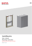
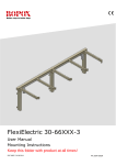
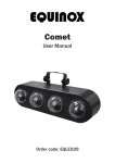
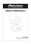
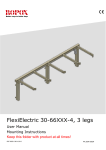
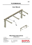
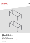
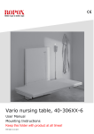
Diagonal, 30-409xx-4 User manual Mounting instruction Keep this folder with product at all times! PDF 6117 / 30.09.2014 Page 1 © Ropox 2014 Table of Contents TABLE OF CONTENTS .............................................................................................................................. 1 1. INTRODUCTION .................................................................................................................................. 3 2. COMPLIANCE WITH EU-DIRECTIVES .............................................................................................. 3 3. APPLICATION...................................................................................................................................... 3 4. TECHNICAL DATA .............................................................................................................................. 4 5. SCHEMATIC DIAGRAM OF FRAME .................................................................................................. 5 5.1 5.1.1 5.1.2 5.1.3 5.1.4 6. Tips and tricks ............................................................................................................................ 6 Tension of bolt connections to wall ............................................................................................ 6 Wall unit sizes............................................................................................................................. 6 Wiring to control switch .............................................................................................................. 7 Fixed cupboards ......................................................................................................................... 7 MOUNTING INSTRUCTIONS, ILLUSTRATIONS ............................................................................... 7 6.1. Connection of cables ................................................................................................................... 11 6.2 Mounting of cable support for net cable ....................................................................................... 14 6.3 Mounting of cabinets ..................................................................................................................... 14 6.4 Montage af sikkerhedsstop ........................................................................................................... 16 6.4.1 Placement possibility’s ............................................................................................................... 16 6.4.2 Mounting on cabinet .................................................................................................................. 17 6.5 Connection of safetystop .............................................................................................................. 19 7. MOUNTING INSTRUCTIONS FOR 2 UNITS .................................................................................... 21 7.1 Connection of cables .................................................................................................................... 21 7.2 Mounting of cable support for net cable ....................................................................................... 23 7.3 Mounting of cabinets ..................................................................................................................... 25 7.4 Mounting of safetystop.................................................................................................................. 25 8. PERFORMANCE TEST ..................................................................................................................... 27 9. LIST OF COMPONENTS FOR DIAGONAL, L=40-180CM ............................................................... 28 10. OPTIONS FOR DIAGONAL ............................................................................................................... 30 11. PLACING OF LED SPOT ................................................................................................................... 32 12. SAFETY IN USE ................................................................................................................................. 33 13. CLEANING AND MAINTENANCE..................................................................................................... 34 13.1 Cleaning of frame ..................................................................................................................... 34 13.2 Maintenance ............................................................................................................................. 34 13.3 Service schedule, operation and maintenance ........................................................................ 35 14. TROUBLE SHOOTING ...................................................................................................................... 36 14.1 The height of the frame cannot be adjusted ............................................................................... 36 15. CE-MARKING..................................................................................................................................... 37 16. COMPLAINTS .................................................................................................................................... 38 Page 2 © Ropox 2014 1. Introduction Diagonal is an electric height adjustable frame for wall units. Diagonal is especially suitable for wheelchair users or persons who normally have difficulties reaching upper shelves in wall units. This document must ALWAYS accompany the product and be read by and available to users All users must follow these instructions. It is very important that the instructions have been read and understood prior to operation of the product. This instruction must be accesseble to the user and keept with the product if it is moved to another place. If this product is electrically adjustable in height there is a risk of trapping. The product must therefore always be operated by or under the guidance of an experienced adult, who has read and understood the importance of section 10 “Safety in use” The correct use, operation and inspection are decisive factors for efficient and safe performance. 2. Compliance with EU-Directives This product has CE-marking according to the current Machinery, EMC and Low Voltage Directives and thus complies with the basic safety requirements. See separate CE-declaration, section 13. If these frames are assembled or otherwise connected with other electrical components, this will be considered a new unit. Consequently, the assembled unit must be subject to a risk assessment, after which the CE mark may be awarded. 3. Application Diagonal is designed to obtain optimum working height for the user. Diagonal has been designed for height adjustment of wall units. Diagonal must NOT be used as a lifting table or person lifter. The product must be used indoor, under normal room temperatures and humidity as stated in section 4. The control unit complies with IP32/ll and must always be installed in accordance with the national Heavy Current Regulations or corresponding national or international standards. Page 3 © Ropox 2014 4. Technical data Product name: Diagonal Item numbers: Item numbers: Width of wall units 40-180 cm : 30-409xx- X = 04-18 Material: Welded steel tubes St. 37 and various plastic components. Surface treatment: Blue chromate, powder coating. Power supply: 230VAC / 2,5A / 50Hz Standby primary: 1W Control voltage: 24VDC Duty circle.: Max. 4 min. active then 18 min. pause Max. load of frame: 120 kg evenly distributed over the frame Speed: Approx. 2 mm/sec - Approx. 23 sec for a complete stroke Temperature: 5-45° C Air humidity: 5-85% (non-condensing) Complaints: See Complaints, page 36 Producer: Ropox A/S, DK-4700 Naestved, Tlf.: +45 55 75 05 00 E-mail: [email protected] - www.ropox.com Page 4 © Ropox 2014 5. Schematic diagram of frame Its important that electrical connections to control unit are flexible and can move freely within the range of adjustment of frame. Conditions for schematic diagram: Height of wall units = 704 mm – (with another height of wall unit regulate diagram accordingly) (Wall unit heights that can be used, 704-920 mm) Height of upper edge of wall unit = 2120 mm (if another height required, regulate diagram accordingly) 115 +-3 330 * ** *** * Height can be individual adjusted ** Depends of height to top of cabinet *** Depends of height to top of cabinet and cabinet size Page 5 © Ropox 2014 5.1 Tips and tricks 5.1.1 Tension of bolt connections to wall 120 Kg incl. Wall unit The maximal load must be evenly distributed in the entire wall unit. As example we have put max load in front edge of wall unit. This calculation presupposes fixation of 9 bolts. 120 x 44 21 x 9 Tension upper bolts: = 28 Kg/bolt Safety factor must be used: Safety factor 1 Safety factor 2 Safety factor 3 28 Kg/bolt 56 Kg/bolt 84 Kg/bolt 210 mm This is subject to min. 9 bolts having optimum fixation to wall. 440 mm Wall unit sizes 704-920 mm 5.1.2 330 mm Obs! – If Safety stop plate is not being used, wall units with less depth can be used! Page 6 © Ropox 2014 5.1.3 Wiring to control switch Pull down cable from wall units to edge of worktop for placement of control button. We recommend a build-in pipe in wall where the cable can be pulled through (ø3cm). If a high wall unit is placed right next to a Diagonal, it is an advantage to pull the cable for the control trough wall unit then a pipe in wall can be avoided. L = ca. 3500 mm + 5.1.4 Fixed cupboards An Installation of Diagonal frame shifts & places the wall cupboards 115mm +-3mm out from the wall. If you require/wish for any existing fixed cupboards to be in line with Diagonal we recommend an installation of the Diagonal first. In this way the best result is ensured. 115mm +-3 Page 7 © Ropox 2014 6. Mounting instructions, illustrations Assembly must always be carried out by competent personnel Prior to assembly check that all parts have been provided. See list of components, section 8 Height of top wall unit (edge) = 2120 mm – see schematic diagram page 5 Page 8 © Ropox 2014 Page 9 © Ropox 2014 Page 10 © Ropox 2014 Loosen the nut that keeps the cable track in place, pull cable track aside Page 11 © Ropox 2014 Mount the unit to the wall. Put the cable track back in place and tighten nut. Page 12 © Ropox 2014 6.1. Connection of cables 1: Connect the net cable and turn on the power 2: Connect the motor cable to M1 3: Connect the handswitch to white spiral cable. When the handswitch is placed at the desired position, Cable support for control switch can be mounted Move the frame to bottom position for reset Page 13 © Ropox 2014 6.2 Mounting of cable support for net cable Recommended placement, seen from above: To the left of the box Recommended placement, seen from side: Lower than the cabinet plate. The cable support will be hidden in top position Page 14 © Ropox 2014 6.3 Mounting of cabinets Attach cupboards to sliding frame and fasten Fasten cupboard at the bottom Page 15 © Ropox 2014 6.4 Montage af sikkerhedsstop Safety Stop is an accessory for diagonal 6.4.1 Placement possibility’s Cabinet: 704mm – 920mm 1: The safetystop is mounted flush with the front of the cabinet Cabinet: 330mm Safetystop: 370mm Door: 16-20mm From wall to saftystop: 445mm Page 16 © Ropox 2014 Cabinet: 704mm – 920mm 2: The safetystop is mounted flush with the front of the cabinet door Cabinet: 330mm 14-18mm Safetystop: 370mm From wall to saftystop: 461mm – 465mm Page 17 Door: 16-20mm © Ropox 2014 6.4.2 Mounting on cabinet Place the safetystop in center, under the cabinet. The safetystop can be mounted flush with cabinet or cabinet door. Hold the safetystop in place with a clamp. Screw the safetystop to cabinet. Page 18 © Ropox 2014 6.5 Connection of safetystop In the right side of the safetystop there is a yellow 2,2kΩ resistor mounted. Remove yellow 2,2kΩ resistor from the cord marked S2 Page 19 © Ropox 2014 Connect extension cord to the cord marked S2 and fasten it with cable binders as shown. Connect the extension cord to the safety stop. Page 20 © Ropox 2014 7. Mounting instructions for 2 units Mount the 2 units as described on page 9-12 Page 21 © Ropox 2014 Page 22 © Ropox 2014 7.1 Connection of cables 1: Connect the net cable and turn on the power Unit 1 2: Connect motor cable from unit 1 to M1 3: Connect motor cable from unit 2 to M2 Unit 2 4: Connect the handswitch to white spiral cable. Move the frame to bottom position for reset Page 23 © Ropox 2014 7.2 Mounting of cable support for net cable See page 14. Page 24 © Ropox 2014 7.3 Mounting of cabinets See page 15 Page 25 © Ropox 2014 7.4 Mounting of safetystop Mount the safetystops as shown on page 16-18 Place plug with yellow 2,2kΩ resistor on the right side of safety stop plate (shown from the front) Connect the two cables for safety stop plates in the middle Page 26 Connect extension cable of control box to safety stop plate on the left side (shown from the front) and fasten it with cable binders as shown on page 20 © Ropox 2014 8. Performance test After installation and prior to use all functions of unit must be tested. The test must be carried out by competent personnel. Subsequently the test shall be carried out once a year. Testing prior to connection to mains voltage: 1. Check that mounting instructions have been observed 2. Check that all bolts have been tightened. 3. Check that all cables have been connected correctly and that the plugs have been pressed home. 4. Check that there is no load on the frame. 5. Check that there is nothing preventing the frame from moving freely within the height adjustment range. Start-up Procedure 1. Connect the net cable and turn on the power 2. Connect the motor cables to M1 (M2) 3. Connect the control switch to HS 4. Press DOWN on the control switch, move the frame to bottom position, check that the movement is even and smooth. Make sure that the hose connections follow the movement of the frame and that they do not get squeezed. The frame is now reset. 5. Press UP on the control switch, move the frame to top position and check that the movement is even and smooth. Make sure that the hose connections follow the movement of the frame and that they do not get squeezed. If safety stop has been mounted under the wall unit it must be tested as follows: Press DOWN on control switch and let frame move 2-5 cm downwards, activate the safety stop. The frame must stop downwards movement and move 1-2 cm upwards and stop. If a smart box has been mounted – (is used if a FlexiElectric has been mounted below this unit) follow additional instructions for smart box. If all test are ok, the frame is ready for use. See section 10 “Safety in use”. Page 27 © Ropox 2014 9. List of components for Diagonal, L=40-180cm Diagonal unit 30-40904 til 30-40912: 1 pc. The Diagonal comprises: 30*40999-098 Mounting profile L=40-120cm 1 pc. 30*40999-160 2 pcs. Tube for topprofile Top profile according to width of cabinets: 30*40999-133 Top profile, cabinet width 40cm 30*40999-150 Top profile, cabinet width 50cm 30*40999-104 Top profile, cabinet width 60cm 30*40999-135 Top profile, cabinet width 70cm 30*40999-137 Top profile, cabinet width 80cm 30*40999-139 Top profile, cabinet width 90cm 30*40999-141 Top profile, cabinet width 100cm 30*40999-143 Top profile, cabinet width 110cm 30*40999-117 Top profile, cabinet width 120cm 1 pc. 1 pc. 1 pc. 1 pc. 1 pc. 1 pc. 1 pc. 1 pc. 1 pc. Bottom profile according to width of cabinets: 30*40999-124 Bottom profile, cabinet width 40cm 30*40999-123 Bottom profile, cabinet width 50cm 30*40999-144 Bottom profile, cabinet width 60cm 30*40999-125 Bottom profile, cabinet width 70cm 30*40999-126 Bottom profile, cabinet width 80cm 30*40999-127 Bottom profile, cabinet width 90cm 30*40999-128 Bottom profile, cabinet width 100cm 30*40999-129 Bottom profile, cabinet width 110cm 30*40999-115 Bottom profile, cabinet width 120cm 1 pc. 1 pc. 1 pc. 1 pc. 1 pc. 1 pc. 1 pc. 1 pc. 1 pc. 95091442 Screws for profiles 6 pcs Diagonal unit 30-40913 til 30-40918: 2 pcs. The Diagonal comprises: 30*40999-148 Mounting profile L=130-180cm 1 pc. 30*40999-160 4 pcs. Tube for topprofile Top profile according to width of cabinets: 30*40999-133 Top profile, cabinet width 130cm 30*40999-150 Top profile, cabinet width 140cm 30*40999-104 Top profile, cabinet width 150cm 30*40999-135 Top profile, cabinet width 160cm 30*40999-137 Top profile, cabinet width 170cm 30*40999-137 Top profile, cabinet width 180cm 2 pc. 2 pc. 2 pc. 2 pc. 2 pc. 2 pc. Bottom profile according to width of cabinets: Page 28 © Ropox 2014 30*40999-151 30*40999-152 30*40999-153 30*40999-154 30*40999-155 30*40999-118 Bottom profile, cabinet width 130cm Bottom profile, cabinet width 140cm Bottom profile, cabinet width 150cm Bottom profile, cabinet width 160cm Bottom profile, cabinet width 170cm Bottom profile, cabinet width 180cm 1 pc. 1 pc. 1 pc. 1 pc. 1 pc. 1 pc. 95091442 . Screws for profiles 16 pcs. Control box for L=40-120cm(26,5x10,5x3,7 cm) 30*40903-008: The control box comprises: 96000592 Power cable 1 pc. 93000164 Extension cord 350 cm + spiral For control switch, white 1 pc. 30-67840 Standard switch, (3x6 cm) Incl. 150 cm cable 1 pc. 96000155 Adhesive plate 10 pcs. 96000165 Strips black 10 pcs. 95134017 Screw countersink 4x17 35 pcs. Control box for L=130-180cm(26,5x10,5x3,7 cm) 30*40903-009: The control box comprises: 96000592 Power cable 1 pc. 93000164 Extension cord 350 cm + spiral For control switch, white 1 pc. 30-67840 Standard switch, (3x6 cm) Incl. 150 cm cable 1 pc. 96000155 Adhesive plate 10 pcs. 96000165 Strips black 10 pcs. 95134017 Screw countersink 4x17 35 pcs. Page 29 © Ropox 2014 10. Options for Diagonal Split cable 96000629: To be used if more than one control 1 pc. Infra-red control 30-67847: Remote control via infra-red receiver (cable 250 cm) Range 150-200 cm Large press pad (14x7 cm) 30-67841: For disabled people, incl. 150 cm cable 1 pc. 1 pc. Safety stop plate 30-416xx: Safety circle with extension cable (cable 250 cm) Steel plate with mounting parts and plate. 1 pc. Smartbox 30-69002-1: 1 pc. Option for safety stop plate To be ordered if Diagonal is mounted above a FlexiElectric Extension cord 30-67870: 1 pc. 250 cm (black) for safety stop Spiral extension 30-67871: L =25-100 cm (black) for safety stop 1 pc. Page 30 © Ropox 2014 Safety stop with LED spot 12V 10W Inkl. transformer. Incl. cables 30-42604 Led for 40cm Safetystop 1pc 30-42605 Led for 50cm Safetystop 1pc 30-42606 Led for 60cm Safetystop 1pc 30-42607 Led for 70cm Safetystop 2pc 30-42608 Led for 80cm Safetystop 2pc 30-42609 Led for 90cm Safetystop 2pc 30-42610 Led for 100cm Safetystop 2pc 30-42611 Led for 110cm Safetystop 2pc 30-42612 Led for 120cm Safetystop 2pc 30-42613 Led for 130cm Safetystop 3pc 30-42614 Led for 140cm Safetystop 4pc 30-42615 Led for 150cm Safetystop 4pc 30-42616 Led for 160cm Safetystop 4pc 30-42617 Led for 170cm Safetystop 4pc 30-42618 Led for 180cm Safetystop 4pc Page 31 © Ropox 2014 11. Placing of LED spot If LED spots are purchased, they will be positioned as shown on drawing below. Page 32 © Ropox 2014 12. Safety in use The VertiElectric should only be used by people who have read and understood these instructions.. VertiElectric is a height-adjustable frame, and we recommend the filling of a safety stop beneath in order to guard against trapping. Even though a safety stop plate has been mounted always make sure that there are no people, animals or objects under the frame during height adjustment. VertiElectric is a wall unit and must not be used as lifting equipment or person lifter. Always use the frame so there is no risk of damage to people or property. The person, who operates the frame, is responsible for avoiding damage or injury. Children and people with reduced observation must only operate the frame under surveillance. If the frame is used in publicly accessible locations where children or people with reduced observation ability may get close to the frame, the person operating the frame must pay sufficient attention in order to prevent dangerous situations. Make sure that there is free space above and below the frame to allow height adjustment. Do not overload the frame and make sure that the load distribution is correct. Do not operate the frame in case of errors or damage. Do not use the frame in an explosive environment. In case of inspections, service and repairs make sure the frame is not loaded, and that main power is disconnected Any modification to the frame, which may influence its operation or construction, is forbidden Installation, service and repairs must only be carried out by competent personnel. If the frame has not been installed in accordance with these mounting instructions, the guarantee may become void. Only use Ropox original spare parts as replacement parts. If other spare parts are used, the guarantee may become void. Page 33 © Ropox 2014 13. Cleaning and maintenance 13.1 Cleaning of frame The frame must not be connected to the mains voltage during cleaning. Do not flush electrical components with water Clean the frame with a damp cloth using lukewarm water and ordinary cleaning agents. Do not use Corrosive/abrasive liquids or abrasive cloths, brushes or sponges. After cleaning dry the frame. 13.2 Maintenance Inspections, service and repairs must be carried out by competent personnel The frame is maintenance-free and moving parts have been lubricated for life. For reasons of safety and reliability we recommend inspection of the frame once a year: Check that all bolts have been tightened. Check that the frame moves freely from bottom to top position without problems. Check that all cables have been fitted correctly and are undamaged.. After each inspection the service schedule shall be filled in. Only use Ropox original spare parts as replacement parts. If other parts are used, the guarantee may become void Page 34 © Ropox 2014 13.3 Service schedule, operation and maintenance Service and maintenance Serial No.: Service and maintenance Serial No.: Date: Date: Sign: Sign: Remarks: Remarks: Service and maintenance Serial No.: Service and maintenance Serial No.: Date: Date: Sign: Sign: Remarks: Remarks: Page 35 © Ropox 2014 14. Trouble shooting 14.1 The height of the frame cannot be adjusted 1. 2. 3. 4. Check mains and voltage to the control unit and that the power is switched on. Check cables and plug-in connections between control box and motors. Check cables and plug-in connections between control box and control switch. Check cable connections between safety stop plate, and control box. (see mounting instructions page 12). 5. Check that safety stop has not been activated. Reset procedure 6 If none of the above has helped reset the unit: Disconnect motorcables Disconnect mains cable and wait 5 sec Connect mains cable Connect motor cable Move the unit to bottom position for reset. Page 36 © Ropox 2014 15. CE-marking Product name: Diagonal Item no: Item no: Width of wall unit 40-180 cm: 30-40904-4 - 30-40918-4 all belong to risk class I and conform to the Directives and Standards mentioned below: DIRECTIVES The Machinery Directive 2006/42/EC STANDARDS DS/EN 12182: 2012 Assistive products for functionally disabled persons General requirements and test methods DS/EN 14971: 2012 Medical devices – Application of risk management to medical devices Risk analyses according to the Machinery Directive 2006/42/EC DS/EN 60335-1: 2012 Household and similar electrical appliances Safety – Part 1: General requirements Tested by Nemko, Certificate number: NO72162 DS/EN 9999: 2011: Assistive products for functionally disabled persons Classification and terminology Dato: 03-06-2014 Page 37 © Ropox 2014 16. Complaints We refer to our general Terms of sale and delivery on our homepage www.ropox.com Keep this folder with product at all times ROPOX A/S Ringstedgade 221 DK – 4700 Naestved Tel.: +45 55 75 05 00 Fax.: +45 55 75 05 50 E-mail: [email protected] www.ropox.com