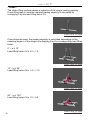
1
>>igvw SQ P1
>>igvw Standards der Qualität Standards of Quality
>>SQP1
Trusses
Oct, 2010
(Mar, 2013)
Table of contents
1
>>igvw SQ P1
Legend
Notes regarding the structure of the standards:
SQ
O
P
Q
1, 2, 3, ...
Standard of Quality
Organisation
Code of practice/working procedure
Qualification
consecutive numbering
O Organisation/Documentation
Internal structure of operations and organisation of businesses
Documentation and certification of processes
P Code of practice/working procedure
Supply and use of working materials
Q Qualification
Qualification of skilled personnel and experts
2
Table of contents
>>igvw SQ P1
Preliminary note
SQ Standards are intended to define the quality levels required of services
provided within the event technology industry.
SQ Standards take into consideration current legal positions and on that basis,
provide a description of the industry’s specialised working procedures.
They contain a summary of the applicable legal standards and requirements in
areas of industrial safety and health protection.
This Quality Standard has been developed by the responsible working group
of the igvw (Entertainment Technology Industry Association) in cooperation
with the DGUV (German Social Accident Insurance) and the working group
of the safety engineers from the German public broadcasting organisations:
ARD, ZDF Medienakademie, ARTE, BR, Bavaria, DR, DW, HR, IRT, MDR,
NDR, ORF, RB, RBB, RBT, RTL, SF, SR, Studio Hamburg, SWR, WDR and
ZDF.
Table of contents
3
>>igvw SQ P1
Notes on use:
This pdf file is annotated with interactive links and bookmarks.
In the table of contents a mouse click on an item leads straight to the
corresponding chapter.
At the bottom of each page there is a link that leads back to the table of
contents.
The links next to the illustrations open up a 3D view (needs Adobe Reader 8.x
or newer). An internet connection is required.
4
Table of contents
>>igvw SQ P1
Table of contents
Preliminary note................................................................................................
1
Area of application.............................................................................7
2
Normative and informal references....................................................7
3
Definitions.....................................................................................9
4
Supply.........................................................................................11
4.1 Constructional requirements...............................................................11
4.2 Information for users..........................................................................12
4.3 Technical documentation....................................................................13
4.3.1 Technical data.....................................................................................13
4.3.2 Loading capacity.................................................................................13
4.3.3 Static analysis....................................................................................13
4.4 Labelling..........................................................................................14
5
Use...................................................................................................14
5.1 Qualification and responsibility............................................................14
5.2 Choice of trusses................................................................................15
5.3 Installation of trusses..........................................................................15
5.4 Force transmission in trusses............................................................17
5.5 Lifting trusses………...........................................................................17
5.5.1 Equipment for lifting and load suspension.........................................17
5.5.2 Methods of lifting trusses....................................................................18
5.6 Safety precautions during assembly and operation.............................21
6
Inspections....................................................................................22
6.1 Basic principles of inspections............................................................22
6.2 Inspections before use.......................................................................22
6.2.1 Inspections before manufacture .........................................................22
6.2.2 Inspections before entry into service....................................................23
6.3 Inspections during use......................................................................24
6.3.1 Inspections during set-up and operation.............................................24
6.3.2 Regular inspections............................................................................25
6.3.3 Extraordinary inspections..................................................................25
6.4 Documentation............................................................................25
Appendix
I
Lifting trusses..................................................................................27
II A sample list of contents for a static analysis..................................31
III A sample handover protocol............................................................32
IV Scope of inspection after assembly................................................33
Literature references.......................................................................................34
Table of contents
5
>>igvw SQ P1
The solutions described in this igvw Standard do not rule out the validity of
other solutions that guarantee the same standard of safety, as laid down within
the technical regulations of other member nations of the European Union or
Turkey, or other member states of the European Economic Area.
Please note:
Wherever possible gender-free nouns and pronouns have been used. Where
this is not possible the male noun or pronoun has been used to improve
readability, but also is meant to refer to females.
6
Table of contents
>>igvw SQ P1
1 Area of application
This standard applies to the supply and use of trusses and constructions
made from trusses in the setup of productions and events.
2 Normative and informal references
BGI 638 edition 1998
Information regarding rope ladders
BGI 810 edition 03-2008
Safety at productions and events - guidelines
DIN 4113 – 1/A1: 2002-09
Aluminium constructions under predominantly static loading – Part 1:
calculations and structural design
DIN 4113 – 1/A1 Amendment 1: 2008-12
Aluminium constructions under predominantly static loading – Part 1:
calculations and structural design
DIN 4113 - 2: 2002-09
Aluminium constructions under predominantly static loading – Part 2:
calculations of welded aluminium constructions
DIN 4113 - 2 Amendment: 2008-12
Aluminium constructions under predominantly static loading – Part 2:
calculations of welded aluminium constructions
DIN V 4113 - 3: 2003-11
Aluminium constructions under predominantly static loading – Part 3: design
and qualification of manufacturers
DIN V 4113 – 3 Amendment: 2008-12
Aluminium constructions under predominantly static loading – Part 3: design
and qualification of manufacturers
DIN 18800 - 1: 2008-11
Steel structures – Part 1: design and construction
DIN 18800 - 2: 2008-11
Steel structures – Part 2: stability – bending of bars and skeletal structures
Table of contents
7
>>igvw SQ P1
DIN 18800 - 7: 2008-11
Steel structures – Part 7: design and qualification of manufacturers
igvw SQ Q2
Expert in event rigging
DIN VDE 0100-540: 2008-01
low voltage electrical installations Parts 5-54: selection and erection of
electrical equipment – protective earthing construction, protective earthing
conductors
8
Table of contents
>>igvw SQ P1
3 Definitions
Truss
structural element made of metallic material
Truss construction
a structure made by combining a number of trusses
Truss connector
component used to connect trusses
Truss adapter (Gizmo, Bracket, Loadbar)
load-carrying equipment made of metal bars with a suspension point and pipe
clamps for connecting trusses and suspension- or load-bearing equipment
Chord (chord beam)
longitudinal bar of a truss
Brace (cross-brace)
bar running diagonally, vertically or horizontally
Sleeve Block
guide block used for moving trusses and truss constructions vertically on
towers
Tower
vertical column
Manufacturer
maker of products, i.e. the person who buys materials or pre-fabricated
elements and makes them into a product
Loading capacity
the load which a truss can safely carry
Truss node
joint connecting chord and brace
End plate
flat steel plate forming the end of a truss
Uniformly distributed load (UDL)
a load that is spread equally along the length of the truss
Table of contents
9
>>igvw SQ P1
Third point
positions of two loads placed symmetrically each at one third of the total
length
Quarter point
positions of three loads placed symmetrically each at one quarter of the total
length
Normal force
total internal force acting along the longitudinal axis of a truss or one of its
parts (e.g. chord)
Shear force
total internal force acting laterally on a truss or one of its parts (e.g. chord)
Bending moment
total internal force which causes bending of a truss or one of its parts (e.g.
chord)
Single-span girder
Truss with two supports
Multi-span girder
Truss with more than two supports
Jib or cantilever
Truss which projects beyond a support, thus basically a beam supported at
only one end
10
Table of contents
>>igvw SQ P1
4 Supply
If a contractor is to supply suitable trusses it is necessary during the planning,
choosing and purchasing phases to pay particular attention to the intended
use, environmental influences, ergonomics, and the qualification and
experience of the users.
The contractor may only supply trusses that conform to the specifications laid
down in Part 4 “Supply” and Part 6 “Inspections”.
Only truss connectors and accessories may be used that are approved by
the manufacturer. In general this means that only trusses from the same
manufacturer may be joined together to form a truss construction.
4.1 Constructional requirements
In the construction, structural calculation and production of trusses it is
necessary to apply current legal norms, e.g. laws, regulations, work-safety
regulations and the current state of technology rules. Since trusses are
constructed mainly
of aluminium, DIN 4113 - 1, “Aluminium constructions under predominantly
static loading – Part 1: static analysis and structural design” and DIN 4113 - 2,
“Aluminium constructions under predominantly static loading – Part 2: static
analysis of welded aluminium constructions” are of particular importance.
When other material are used, the appropriate state of technology rules are
to be taken into account, for instance DIN 18800 for trusses made of steel.
Companies that carry out welding operations on supporting elements must be
properly certified.
Note:
The loading capacity of a truss depends on the construction, materials used,
and production. For the structural calculation of the admissible loading
capacity, the appropriate state of technology rules must be applied for all parts
of the truss (chords, braces, wall-thicknesses, connectors, welding seams
.....).
− Aluminium trusses are normally welded constructions made from semifinished products (tubes, plates and bars). The semi-finished products are
often made of wrought aluminium alloy which was rolled out warm and which
becomes softened under the influence of heat.
It is necessary to make allowance for the lower strength of the welding seams
and heat affected zones in comparison with the basic material.
− When different alloys are welded together the specifications of the less
stable material are to be considered relevant.
− Allowance must be made for additional bending moments caused by
Table of contents
11
>>igvw SQ P1
eccentricity of the centroidal axes of the lattice nodes and other relevant parts.
− The joint between two trusses must also be assumed to be the most
vulnerable part of the whole construction, because the modular systems can
be put together in any combination by the user.
− A misalignment of the transmission of force due to end-plates at the joints of
individual trusses causes local bending.
− Bending moments must be taken into account that can be caused by the
application of force or support or suspension outside the framework nodes..
− Documented evidence must be provided about the normal force, bending
moment and shear force of the truss connectors. No permanent distortion may
occur Note:
If trusses are used as a permanent part of physical structures, their
construction is governed by building legislation. In such situations only
trusses may be used that conform with EU building product guidelines and
consequently with German building product laws. Written verification of this
must be provided by the manufacturer of the trusses.
4.2 Information for users
The contractor may only provide trusses for which the manufacturer supplies a
user manual and assembly instructions in German.
The following information in particular must be included to ensure proper
utilisation:
− a definition of the mounting and operating positions
− instructions on the correct assembly of the system elements
− guidance on set-up, dismantling and operation
− instructions on rigging and support (inducing in- and output of forces)
− information on the loading capacity of statically indeterminate
systems (for instance constructions with more than two supports, or box structures)
− information on the loading capacity of jibs
− information on the use of trusses as vertical supports
− information on which dynamic factors were taken as the basis for
the data on loading capacity
− information on protective earthing in particular with regard to trusses that are hanging or inserted or that have coated surfaces
− instructions on handling, storage and transport
− instructions for maintenance (overhauling, servicing, inspections)
− information on the carrying out of regular inspections and criteria for
removal from service
− information on the acquisition of spare parts
12
Table of contents
>>igvw SQ P1
4.3 Technical documentation
The contractor may only provide trusses for which the manufacturer has
supplied, for each type of truss which he manufactures, German-language
documentation with all safety-relevant information.
The technical documentation must in particular include the following
information:
4.3.1 Technical data
− a list of all the parts of the truss type
− technical drawings
− dead weight
− materials used in construction
− a list of accessories
4.3.2 Loading capacity
− maximum uniformly distributed load
− maximum point load in midspan
− maximum point load at the one-third span points
− maximum point load at the one-quarter span points
These values are to be given including details of possible combinations of
trusses as foreseen by the manufacturer, their installation position, the type of
support, suspension and load application.
4.3.3 Static analysis
The contractor may only provide trusses for which the manufacturer can
supply written evidence in German of a certified static analysis (see section
6.2.1) with specification of the criteria of calculation and the norms used.
In addition the following information is also required:
− maximum normal force in the chord profiles (max. n)
− maximum bending moment (max. m)
− maximum shear force (max. s)
Table of contents
13
>>igvw SQ P1
4.4 Labelling
The following must be permanently and visibly attached to the truss:
− manufacturer
− month and year of construction (mm/yy)
− model type
− serial number
− dead weight in kg
5 Use
Only those trusses may be used that conform with the specifications laid
down in section 4 “Supply”. Trusses must be used in accordance with the
specifications listed below. “Use” means the operation, transport, storage,
maintenance, and inspection of working equipment.
5.1 Qualification and responsibility
The job and responsibilities of each participating person must be exactly
defined.
The operator of a building is in particular responsible for the quality, loading
capacity and the condition of the suspension points provided by him within the
building and for the load carrying capacity of the floor. He must provide the
relevant documentation (e.g. a loading capacity plan).
The contractor decides on the qualification required for planning, assembly
and operation according to the results of his risk assessment. See also igvw
SQ Q2 “competence in event rigging”.
14
Table of contents
>>igvw SQ P1
5.2 Choice of trusses
A decision on which trusses are suitable must be made on the basis of the
following criteria:
- the static system (e.g. spans with two supporting points or multiple supporting point constructions)
- the width of the span between the supports
- main loads (dead weight + payload), static for installation without hoisting equipment
- main loads (dead weight + payload), static and if necessary dynamic for installation with hoisting equipment
- live loads (e.g. wind or snow)
- load distribution (point load, uniform load, area load)
- additional loading due to persons working on trusses / truss constructions
- additional loading due to measures taken to prevent persons falling
ease of handling
For types of construction and loading not covered by the user manual,
additional static analysis is required (particularly with regard to stability and
load carrying capacity). Static analysis should be carried out by persons who
have completed a relevant degree course and who can show that they have
at least three years experience in construction, static analysis or inspection of
event technology equipment.
5.3 Installation of trusses
During installation, all set-up and utilisation instructions ensuing from the
planning stage must be adhered to.
Stability and load-bearing strength must be guaranteed at all times.
All constructional elements (trusses, connectors etc.) must be subjected to a
visual inspection before assembly begins. If there are any obvious defects,
such as deformation or material reduction of main chords and struts, any
kind of fissure, slot formation at joints or their mountings and deformation
of connectors, these parts may not be used and must be clearly labelled as
defective, in order to prevent them being used by mistake at a later time.
Trusses must be installed using appropriate tools and in the assembly position
planned by the manufacturer.
The supervisor in charge of installation approves the truss construction
for further use. The handover to other users or the operator should be
documented in writing (see Appendix IV Handover Protocol).
Table of contents
15
>>igvw SQ P1
Protective earthing for trusses
Trusses which in the case of an electrical failure could take on dangerous
contact voltages are to be incorporated into a collective protective earthing
system. This applies to all elements made from material that conducts
electricity, upon which equipment is placed or attached to, or through which
wires and cables run, which in the case of an electrical failure could come
into contact which metal parts. Connections can be made with belt clamps,
pipe clamps, bolted connections, or with special unipolar locked socket
connections.
The protective earthing system, laid out in radial form, should at a central point
be connected to the earth of the mains supply.
The minimum wire cross-section must be calculated in accordance with DIN
VDE 0100 Part 540. Experience has shown following cross-sections to be
reliable
- up to 50 m, 16 mm2 Cu (fine stranded copper wire)
- up to 100 m, 25 mm2 Cu (fine stranded copper wire).
In tower systems with movable parts (“sleeve blocks”) the castors or rollers
built into the sleeve block have an insulating effect on the moveable truss
construction. Therefore this must be fitted with an additional protective
earthing conductor. The effectiveness of the protective measures must be
proven.
Lightning protection
When the topography, type of construction or the installation site are such that
lightning could strike easily or have serious consequences, truss constructions
must be fitted with an effective lightning protection system. The effectiveness
of the protective measures must be proven.
If effective lightning protection cannot be guaranteed, the endangered area
must be evacuated during a thunderstorm.
16
Table of contents
>>igvw SQ P1
5.4 Load transmission in trusses
Load transmission means all forms and measures with which the loads
that actually occur are either transmitted to a truss or from it to a support or
suspension point.
The nature and type of load transmission in trusses has a determining
influence on the actual loading capacity of the trusses that are being used.
Load transmission must take place in accordance with the manufacturer’s
instructions.
When loads are transmitted, it is important to ensure that they are distributed
symmetrically on the chords. Lopsided loading can reduce the loading
capacity of the trusses and must be taken into account.
When horizontal and vertical forces occur simultaneously, an applicable static
analysis must be produced.
5.5 Lifting trusses
The type and manner of load transmission determines whether the loading
capacity of the truss and the stability of the truss construction are maintained,
and may only be done by suitably qualified persons.
See igvw SQ Q2 “Competence in event rigging”.
5.5.1 Equipment for lifting and load suspension
Lifting and load suspension equipment is used to support trusses or to Lifting
and load suspension equipment is used to support trusses or to introduce
loads into trusses (See also BGI 810-3 – “Safety at productions and events –
loads over persons”)
Slings are for instance:
− round slings made from synthetic fibre
− round slings with a wire rope core
− lifting straps
− steel ropes (lifting ropes)
− steel chains (lifting chains)
− shackles
− oval suspension devices
− quick-connection swivel-nut devices
− detachable rope end-joints
Load suspension equipment is for instance:
− beam clamps
− truss adapters (gizmo, bracket, loadbar)
Table of contents
17
>>igvw SQ P1
− hanging clamps
The manufacturer’s instructions for the correct use of lifting and load
suspension equipment must always be followed.
When the loading capacity of lifting and load suspension equipment for a
particular field of use has not been verified, it may not be loaded with more
than 0.5 times the loading capacity specified by the manufacturer.
When trusses are put up using synthetic or natural fibre slings, a safety backup of wire rope or lifting chain must be used.
To protect trusses it is permissible to use wire rope with a loose plastic casing,
provided a visual inspection of the wire rope is still possible.
5.5.2 Methods of lifting trusses
When slings are used, the corresponding load lifting factor is determined by
the lifting method used.
The loading capacities, calculated on the basis of the lifting method, must be
halved when persons are underneath the loads.
A distinction is drawn between the following lifting methods:
- Single Fall – (or Drop, Straight, Stinger)
The Single Fall lifting method does not cause a reduction of the sling’s loading
capacity
Load lifting factor 1.0
Link to the 3D view
18
Table of contents
>>igvw SQ P1
- BasketThe Basket lifting method brings about an increase in the loading capacity of
the sling.
The loading capacity is calculated, by multiplying the clamping angle α of the
sling by the corresponding load lifting factor:
0° < α ≤ 12°
Load lifting factor 2.0
Link to the 3D view
12° < α ≤ 90°
Load lifting factor 1.4
Link to the 3D view
90° < α ≤ 120°
Load lifting factor 1.0
Link to the 3D view
Table of contents
19
>>igvw SQ P1
- Choke The choke lifting method causes a reduction of the sling’s loading capacity.
If one lifting rope is used the reduced loading capacity is calculated by
multiplying it by the load lifting factor 0.8.
Link to the 3D view
If two slings are used, the loading capacity is calculated depending on the
clamping angle α of the slings by multiplying it by the corresponding load lifting
factor:
0° < α ≤ 12°
Load lifting factor 0.8 x 2.0 = 1.6
Link to the 3D view
12° < α ≤ 90°
Load lifting factor 0.8 x 1.4 = 1.12
Link to the 3D view
90° < α ≤ 120°
Load lifting factor 0.8 x 1.0 = 0.8
20
Link to the 3D view
Table of contents
>>igvw SQ P1
Lifting methods using clamping angles of α > 120° must be measured
individually.
In addition to the Basket and Choke methods chord tubes may be wrapped
around by the sling without reducing the loading capacity. This wrapping is
done to secure the position of straight truss sections.
5.6 Safety precautions during assembly and operation
In situations when work with trusses involves risks of injury and health hazards
that cannot be eliminated by technical or organisational measures, the
contractor must provide suitable personal protective equipment and other aids
that employees must use in the intended manner.
Technical measures:
The use of scaffolding, hydraulic platforms, ladders or rope ladders made of
metal.
Note:
When rope ladders are used during operation their length may not exceed 5 m
and when they are provided as a means of emergency escape or rescue they
may not exceed 10 m in length (BGI 638: information regarding rope ladders).
Longer rope ladders may only be used in connection with personal protective
equipment against falls.
Rope-assisted ascent and descent: this method may only be used by
experienced and qualified persons.
Organisational measures:
Instruction, restricted access, signs
Person-related measures / personal protective equipment (PPE):
Safety shoes, gloves, protective headgear, hearing protection, PPE against
falls (cf. BGR 198, BGR199 personal protective equipment against falls),
fall-arresting equipment in accordance with DIN EN 341 or DIN EN 1496 in
combination with a safety harness, abseiling devices.
The use of PPE against falls requires particular qualification and ability (see
also igvw SQ Q2).
Additional loads applied to the truss constructions through use of PPE against
falls must be taken into account.
Table of contents
21
>>igvw SQ P1
6 Inspections
The contractor is obliged to provide safe trusses.
In order to ensure that only trusses are put to use that are in a proper
condition, an inspection is necessary, not only before they are first put on the
market, but also before each one is used for the first time.
To ensure that the trusses are safe during set-up and use, they must be
inspected within the framework of their operational use. This way possible
deficiencies or damage can be detected soon enough to be corrected.
Repeated inspections are necessary in order to recognise and correct in due
time, deficiencies and damage that can occur during the operation of trusses.
After significant modification or an overhaul, an inspection is necessary to
check that the truss has been restored to a proper condition.
If, as a result of the inspection, doubts arise about the safety of a truss, this
truss may not be put into use until the defects have been rectified and a
second inspection has shown the truss to be safe.
6.1 Basic principles of inspections
The manufacturer of trusses must make inspections on the basis of
DIN 4113 Part 1,
DIN 4113 Part 2
or
DIN 18800 Part 1.
6.2 Inspections before use
Each purchase leads to a handing-over to the buyer and is concluded with a
formal (commercial or administrative) inspection as to whether the contractual
agreement has been complied with, and with a technical inspection and
the handing-over of the documentation required from the manufacturer or
intermediary.
6.2.1 Inspections before manufacture
The contractor may only provide trusses for which the manufacturer can
supply the following inspection results and documents:
− Manufacturing plant and process
DIN V 4113-3 Aluminium constructions under predominantly static loading – Part 3: execution and qualification of constructors and DIN 18800-7 Steel constructions – Part 7: execution and qualification of constructors.
22
Table of contents
>>igvw SQ P1
− Construction and manufacturing documentation, in particular
functional description, danger and risk assessment, construction and manufacturing documentation and proof of specifications.
− static inspection by a certified test centre for equipment and product safety or a certified civil engineering test centre,
− compliance with the product documentation, in particular construction and loading capacity, safety features (protective earthing connection) and user manuals.
6.2.2 Inspections before entry into service
Before putting a truss into service the contractor must make the necessary
inspections. Truss constructions must be inspected by a person who has
suitable qualifications.
Necessary inspections can be:
- completeness,
- proof of previous inspections,
- declarations of compliance,
- labelling,
- suitability for the designated operational conditions and environmental influences,
- assembly and operating instructions,
- manufacturer’s testing instructions and criteria,
- static analysis and/or certification,
- technical drawings.
The contractor makes sure that the results of the inspections carried out
before entry into service are documented and kept available.
Table of contents
23
>>igvw SQ P1
6.3 Inspections during use
The safe status of the truss should be sustained during use.
Within the framework of the type of use the contractor carries out risk
assessments. In this connection he must determine and evaluate the
influences that cause damage, taking into account the different kinds of
operating modes, and then devise and implement suitable measures to
counteract them.
As a result the contractor decides on the type and extent of the inspections
- after set-up and dismantling,
- after any unusual occurrences,
- as well as on the deadlines for recurring inspections
- and the qualifications demanded of the person who is commissioned to carry them out.
6.3.1 Inspections during set-up and use
During set-up (on-site assembly) and each time before use, the safe condition
of the truss must be established through a visual inspection and functionality
test (see section 5.3).
The visual inspection and functionality test include:
a check for external damage or wear
- provision for the particular circumstances of the surroundings
- protective earthing
- lightning protection
- the documentation of previous inspections (see 6.4)
The qualifications required of the tester depend on the complexity of the truss
construction and the risks related to its use.
24
Table of contents
>>igvw SQ P1
6.3.2 Regular inspections
Trusses and truss constructions are to be inspected according to the type and
frequency of their use, so that defects and damage can be detected in proper
time. The deadlines for inspection are laid down by the contractor as part of
the risk assessment, taking into account
- existing information from the manufacturer,
- influences which may cause damage,
- operative experience,
- other information on the latest state of technology.
During inspections any defects are assessed and decisions made on further
use before the next regular inspection.
An inspection every 12 months by an expert has been proved to be ideal.
The results of the regular inspections must be documented (see section 6.4).
6.3.3 Extraordinary inspections
Extraordinary inspections are necessary in particular:
- in the event of damage
- after a long period of non-use
- after substantial modification of the truss
The replacement of parts with ones of the same type is not considered to be a
substantial modification.
The truss may not be used again until an inspection has proved that safe
operation can be guaranteed.
6.4 Documentation
The results of all inspections are to be documented and available on-site.
For the purpose of depicting the complete history of a truss, it is advisable to
keep all inspection documents together in one file.
Table of contents
25
>>igvw SQ P1
the documentation must be adequate and can contain the following:
declaration of compliance of the manufacturer
- inspection instructions and criteria of the manufacturer
- confirmation of inspections made by the manufacturer
- confirmation of inspections made before entry into service
- inspections made after substantial modification
- risk assessments upon divergence from established inspection intervals
- proof of regular inspections
results of re-examinations
If the documentation is compiled electronically, suitable quality assurance
measures are required.
If inspection stickers are used, company regulations must ensure that the
complete inspection procedure is made transparent.
26
Table of contents
>>igvw SQ P1
Appendix
Appendix I – Lifting trusses
The general rule is that slinging a truss outside its framework
nodes causes local bending strain that can lead to a reduction
in the loading capacity. This fact must be taken into account in
particular with trusses which have a large profile geometry and
a correspondingly large distance between the framework nodes.
The lifting gear should be placed as near to the framework nodes
as possible.
Flexible types of lifting gear, such as round slings, generate
vertical and horizontal forces when used as double strands.
This can lead to a reduction of the loading capacity of the truss.
Flexible lifting gear must be directed in such a way that no
bending load is generated on the cross braces.
Table of contents
27
>>igvw SQ P1
Illustrations of typical lifting methods:
Link to the 3D view
Link to the 3D view
Link to the 3D view
Link to the 3D view
Link to the 3D view
28
Table of contents
>>igvw SQ P1
Link to the 3D view
Link to the 3D view
Link to the 3D view
Link to the 3D view
Table of contents
Link to the 3D view
29
>>igvw SQ P1
Infobox:
Two-chord trusses may
only be lifted by the upper
chord. Attention must
be paid to their lateral
bending behavior.
Link to the 3D view
Link to the 3D view
Link to the 3D view
30
Table of contents
>>igvw SQ P1
Appendix II – A sample list of contents for a static analysis
1 Preliminary notes
1.1 Basis for calculation
1.2 Description of the construction
1.3 Construction materials
1.4 Load assumptions
1.5 Lifting dynamics
2 Profile and permitted internal forces
2.1 Profile data truss type X
2.2 Loading capacity truss type X
2.3 Profile data truss type Y
2.4 Loading capacity truss type Y
2.5 Profile data truss type Z
2.6 Loading capacity truss type Z
3 Verification
3.1 Pressure rods between the rope rolls
3.2 Cross members truss type Z – deflection units
3.2.1 Truss type Z for single rope of the load bar
3.2.2 Truss type Z for picking roll on the counterweights
3.2.3 Verification of the U-profiles
3.3 Lighting bridges
3.4 Framework
3.4.1 Verification truss type X rig
3.4.2 Verification truss type Y tower
3.5 Ground contact pressure / foundations
3.6 Lifting equipment
4 Requirements
Appendix
Computer calculation ground support:
Computer calculation bridges:
Drawings
Table of contents
31
>>igvw SQ P1
Appendix III – A sample handover protocol
Declaration concerning the correct construction and readiness for use of
trusses
manufacturer:
place of manufacture:
company:
address:
person responsible:
customer:
supplier:
company:
address:
person responsible:
The supplier herewith declares to the customer that all equipment and
materials utilised by him conform with the corresponding regulations and
accepted technical standards. He furthermore declares that the complete
assembly of the trusses has been carried out in accordance with the
corresponding regulations and accepted technical standards and that the
truss is handed over to the customer as being ready to use. The required
documents and individual certificates are to be enclosed. These include for
instance material certificates, static calculations or protocols of necessary
inspections which have been carried out.
date: __________ signature of supplier:________________
date: __________ signature of customer:_______________
32
Table of contents
>>igvw SQ P1
Appendix IV – Scope of inspection after assembly
Inspection on the following basis:
plan for set-up and dismantling and plan for operation
materials used
stability against collapse
quality, condition load bearing capacity of
the floor / ground and or
identification-no.
dimensions
Table of contents
distance between supports
ballasting
33
>>igvw SQ P1
Literature references
Literaturhinweise
BGV C1/GUV C1
Veranstaltungs-und Produktionsstätten für szenische Darstellung
BGG/GUV-G 912 Ausgabe 04-2009
Grundsätze für die Prüfung von maschinentechnischer Einrichtungen in
Bühnen und Studios
BGI 810-3 Ausgabe 03-2007
Sicherheit bei Produktionen und Veranstaltungen – Lasten über Personen
BGI 638 Ausgabe 1998
Merkblatt für Seilleitern
BGR 198 Ausgabe 04-1998
Einsatz von persöhnlichen Schutzausrüstungen gegen Absturz
BGR 199 Ausgabe 04-2004
Einsatz von persöhnlichen Schutzausrüstungen zum Retten aus Höhen und
Tiefen
BGR 500 Ausgabe 04-2008
Betreiben von Arbeitsmitteln
DIN 5688 – 3: 2007-04
Anschlagketten – Teil 3: Einzelglieder, Güteklasse 8
DIN 56950: 2005-04
Veranstaltungstechnik – Maschinentechnische Einrichtungen –
Sicherheitstechnische Anforderungen und Prüfung
DIN 18000: 2003-04
Modulordnung im Bauwesen
DIN 18808: 1994-10
Stahlbauten – Tragwerke aus Hohlprofilen unter vorwiegend ruhender
Beanspruchung
DIN EN 1496: 2007-01
Persöhnliche Absturzschutzausrüstungen - Rettungshubgeräte
34
Table of contents
>>igvw SQ P1
EN 287-1: 2006-05
Prüfung von Schweißern - Schmelzschweißen - Teil 1: Stähle
EN 341: 2006-06
Persöhnlicher Arbeitsschutz – Abseilgeräte zum Retten
DIN EN 353-2: 2002-09
Persönliche Schutzausrüstung gegen Absturz – Teil 2: Mitlaufende
Auffanggeräte einschließlich beweglicher Führung
DIN EN 360: 2002-09
Persönliche Schutzausrüstung gegen Absturz – Höhensicherungsgeräte
DIN EN 361: 2002-09
Persönliche Schutzausrüstung gegen Absturz – Auffanggurte
DIN EN 363: 2008-05
Persönliche Absturzausrüstung gegen – Persönliche Absturzschutzsysteme
DIN EN 364: 1993-02
Persönliche Schutzausrüstung gegen Absturz; Prüfverfahren
DIN EN 818-4: 2008-12
Kurzgliedrige Rundstahlketten für Hebezeuge - Sicherheit - Teil 4:
Anschlagketten - Güteklasse 8
DIN EN 818-6: 2008-12
Kurzgliedrige Rundstahlketten für Hebezeuge - Sicherheit Teil 6:
Anschlagketten - Festlegungen zu Informationen über Gebrauch und
Instandhaltung, die vom Hersteller zur Verfügung zu stellen sind
DIN EN 1492-1: 2009-05
Textile Anschlagmittel - Sicherheit - Teil 1: Flachgewebte Hebebänder aus
Chemiefasern für allgemeine Verwendungszwecke
DIN EN 1492-2: 2009-05
Textile Anschlagmittel – Sicherheit -Teil 2: Rundschlingen aus Chemiefasern
für allgemeine Verwendungszwecke
DIN EN 1677 – 1: 2009-03
Einzelteile für Anschlagmittel – Sicherheit – Teil 1: Geschmiedete Einzelteile,
Table of contents
35
>>igvw SQ P1
Güteklasse 8
DIN EN 1677 – 4: 2009-03
Einzelteile für Anschlagmittel – Sicherheit – Teil 4: Einzelglieder, Güteklasse 8
DIN EN 1677 – 5: 2009-03
Einzelteile für Anschlagmittel – Sicherheit – Teil 5: Geschmiedete Haken mit
Sicherungsklappe, Güteklasse 4
DIN EN 1677 – 6: 2009-03
Einzelteile für Anschlagmittel – Sicherheit – Teil 6: Einzelglieder - Güteklasse 4
DIN EN 10002-1: 2001-12
Metallische Werkstoffe - Zugversuch – Teil 1: Prüfverfahren bei
Raumtemperatur
DIN EN 13411-1: 2009-02
Endverbindungen für Drahtseile aus Stahldraht – Sicherheit – Teil 1: Kauschen
für Anschlagseile aus Stahldrahtseilen
DIN EN 13411-2: 2009-02
Endverbindungen für Drahtseile aus Stahldraht – Sicherheit – Teil 2: Spleißen
von Seilschlaufen für Anschlagseile
DIN EN 13411-3: 2009-02
Endverbindungen für Drahtseile aus Stahldraht – Sicherheit – Teil 3:
Pressklemmen und Verpressen
DIN EN 13411-4: 2009-02
Endverbindungen für Drahtseile aus Stahldraht – Sicherheit – Teil 4:
Vergießen mit Metall und Kunstharz
DIN EN 13411-5: 2009-02
Endverbindungen für Drahtseile aus Stahldraht – Sicherheit – Teil 5:
Drahtseilklemmen mit U-förmigem Klemmbügel
DIN EN 13411-6: 2009-04
Endverbindungen für Drahtseile aus Stahldraht – Sicherheit – Teil 6:
Asymmetrische Seilschlösser
DIN EN 13411-7: 2009-04
Endverbindungen für Drahtseile aus Stahldraht – Sicherheit – Teil 7:
Symmetrische Seilschlösser
36
Table of contents
>>igvw SQ P1
DIN EN 13411-8: 2009-04
Endverbindungen für Drahtseile aus Stahldraht – Sicherheit – Teil 8:
Stahlfittinge und Verpressungen
DIN EN 13414-1: 2009-02
Anschlagseile aus Stahldrahtseilen – Sicherheit – Teil 1: Anschlagseile für
allgemeine Hebezwecke
DIN EN 13414-2: 2009-02
Anschlagseile aus Stahldrahtseilen – Sicherheit – Teil 2: Vom Hersteller zu
liefernde Informationen für Gebrauch und Instandhaltung
DIN EN 13414-3: 2009-02
Anschlagseile aus Stahldrahtseilen – Sicherheit – Teil 3: Grummets und
Kabelschlag-Anschlagseile
DIN EN 13889: 2009-02
Geschmiedete Schäkel für allgemeine Hebezwecke – Gerade und geschweifte
Schäkel – Güteklasse 6 – Sicherheit
igvw SQ P2 Elektrokettenzüge
ISO 10042: 2006-02
Schweißen - Lichtbogenschweißverbindungen an Aluminium und seinen
Legierungen - Bewertungsgruppen von Unregelmäßigkeiten
Table of contents
37
>>igvw SQ P1
Herausgeber:
in Zusammenarbeit mit
Informationen unter:
www.igvw.org
38
Table of contents