1
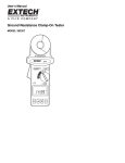
ENGLISH User manual Copyright HT ITALIA 2014 Release EN 2.01 - 13/03/2014 T2000-T2100 Table of contents: 1. PRECAUTIONS AND SAFETY MEASURES ................................................................ 2 1.1. 1.2. 1.3. 1.4. Preliminary instructions ........................................................................................................2 During use ............................................................................................................................3 After use ...............................................................................................................................3 Definition of measurement (overvoltage) category ..............................................................3 2. GENERAL DESCRIPTION ............................................................................................ 4 2.1. Measuring average values and TRMS values .....................................................................4 2.2. Definition of true root mean square value and crest factor ..................................................4 3. PREPARATION FOR USE ............................................................................................ 5 3.1. Initial checks ........................................................................................................................5 3.2. Instrument power supply ......................................................................................................5 3.3. Calibration ............................................................................................................................5 3.4. Storage ................................................................................................................................5 4. OPERATING INSTRUCTIONS ..................................................................................... 6 4.1. Instrument description ..........................................................................................................6 4.2. Description of function keys .................................................................................................6 4.3. Display description ...............................................................................................................7 4.4. Switching on/off the instrument ............................................................................................8 4.5. Resistance measurement ....................................................................................................9 4.5.1. Operating principle ........................................................................................................................ 9 4.5.2. Clamp operation check................................................................................................................ 10 4.5.3. Methods for resistance measurement on earth rods .................................................................. 11 4.5.3.1. Multiple-rod systems ..................................................................................................................... 11 4.5.3.2. System composed of a single rod ................................................................................................. 12 4.5.4. HOLD........................................................................................................................................... 15 4.5.5. MEM ............................................................................................................................................ 15 4.5.6. Anomalous situations .................................................................................................................. 15 4.6. Current measurement (T2000)...........................................................................................16 4.6.1. HOLD........................................................................................................................................... 16 4.6.2. MEM ............................................................................................................................................ 17 4.6.3. Anomalous situations .................................................................................................................. 17 4.7. Leakage current measurement (T2000).............................................................................18 4.7.1. HOLD........................................................................................................................................... 18 4.7.2. MEM ............................................................................................................................................ 19 4.7.3. Anomalous situations .................................................................................................................. 19 4.8. Managing the memory .......................................................................................................20 4.8.1. Storage of data in the memory .................................................................................................... 20 4.8.2. Recalling the results stored in the instrument’s memory ............................................................ 20 4.8.3. Deleting the last datum saved ..................................................................................................... 21 4.8.4. Deletion of all saved data ............................................................................................................ 21 4.9. Setting of alarm thresholds ................................................................................................22 4.10. RS232 communication with a Master instrument (T2100) .................................................23 5. MAINTENANCE .......................................................................................................... 24 5.1. General information............................................................................................................24 5.2. Battery replacement ...........................................................................................................24 5.3. Cleaning the instrument .....................................................................................................24 5.4. End of life ...........................................................................................................................24 6. TECHNICAL SPECIFICATIONS ................................................................................. 25 6.1. Reference conditions .........................................................................................................25 6.2. Technical characteristics ....................................................................................................25 6.2.1. Reference guidelines................................................................................................................... 26 6.2.2. General characteristics................................................................................................................ 26 6.3. Environment .......................................................................................................................26 6.3.1. Environmental conditions for use ................................................................................................ 26 6.4. Accessories provided .........................................................................................................26 7. SERVICE ..................................................................................................................... 27 7.1. Warranty conditions ...........................................................................................................27 7.2. Service ...............................................................................................................................27 EN – 1 T2000-T2100 1. PRECAUTIONS AND SAFETY MEASURES This manual refers to two models: T2000 and T2100. Further in this manual, the word “instrument” will be used to generically refer to both models unless otherwise specified. The instrument has been designed in compliance with directive IEC/EN61010-1 relevant to electronic measuring instruments. For your safety and in order to prevent damaging the instrument, please carefully follow the procedures described in this manual and read all notes preceded by the symbol with the utmost attention. Before and after carrying out the measurements, carefully observe the following instructions: Do not carry out any current measurement in humid environments. Do not carry out any measurements in case gas, explosive materials or flammables are present, or in dusty environments. Avoid any contact with the circuit being measured, even if no measurements are being carried out. Avoid any contact with exposed metal parts, with unused measuring probes, circuits, etc. Do not carry out any measurement in case you find anomalies in the instrument such as deformation, breaks, substance leaks, absence of display on the screen, etc. In this manual, and on the instrument, the following symbols are used: CAUTION: observe the instructions given in this manual; improper use could damage the instrument, its components and create dangerous situations for the operator. High voltage danger: electrical shock hazard. Double-insulated meter Connection to earth 1.1. PRELIMINARY INSTRUCTIONS This instrument has been designed for use in environments of pollution degree 2. The instrument can be used for Resistance measurements (T2000 and T2100) and AC current measurements (T2000) on installations with overvoltage category CAT III 150V to earth. For a definition of measurement categories, see § 1.4. We recommend following the normal safety rules devised by the procedures for carrying out operations on live systems and using the prescribed PPE to protect the user against dangerous currents and the instrument against incorrect use. The instrument can be used on TT, TN and IT electrical systems of industrial, civil, medical or zoo-technical type, both under ordinary conditions where contact voltage limit is 50V, and under special conditions where contact voltage limit is 25V. We recommend following the normal safety rules devised to protect the user against dangerous currents and the instrument against incorrect use. Only the accessories provided together with the instrument will guarantee safety standards. They must be in good conditions and replaced with identical models, when necessary. Do not test circuits exceeding the specified current limits (T2000). Do not perform any test under environmental conditions exceeding the limits indicated in this manual. Check that the batteries are correctly inserted. EN – 2 T2000-T2100 1.2. DURING USE Please carefully read the following recommendations and instructions: CAUTION Failure to comply with the Caution notes and/or Instructions may damage the instrument and/or its components or be a source of danger for the operator. Operate the clamp lever twice before switching on the instrument, to make sure that the clamp jaws are completely closed. When switching on the instrument, DO NOT operate the clamp lever and do not clamp any cable. Avoid measuring resistance if external voltages are present. Even if the instrument is protected, excessive voltage could cause malfunctions. During current measurement (T2000), any other current near the clamp may affect measurement precision. When measuring current (T2000), always put the conductor as near as possible to the middle of the clamp jaw, to obtain the most accurate reading. While measuring, if the value of the quantity being measured remains unchanged, check if the HOLD function is enabled. CAUTION If the symbol “ ” is displayed during use, interrupt testing, disconnect the instrument from the system, switch off the instrument and replace its batteries (see § 5.2). 1.3. AFTER USE When measurements are completed, switch off the instrument by pressing the multifunction key “1” (see § 4.4). If the instrument is not to be used for a long time, remove the batteries. 1.4. DEFINITION OF MEASUREMENT (OVERVOLTAGE) CATEGORY Standard “IEC/EN61010-1: Safety requirements for electrical equipment for measurement, control and laboratory use, Part 1: General requirements” defines what measurement category, commonly called overvoltage category, is. § 6.7.4: Measured circuits, reads: Circuits are divided into the following measurement categories: Measurement category IV is for measurements performed at the source of the lowvoltage installation. Examples are electricity meters and measurements on primary overcurrent protection devices and ripple control units Measurement category III is for measurements performed on installations inside buildings. Examples are measurements on distribution boards, circuit breakers, wiring, including cables, bus-bars, junction boxes, switches, socket-outlets in the fixed installation, and equipment for industrial use and some other equipment, for example, stationary motors with permanent connection to fixed installation Measurement category II is for measurements performed on circuits directly connected to the low-voltage installation. Examples are measurements on household appliances, portable tools and similar equipment. Measurement category I is for measurements performed on circuits not directly connected to MAINS. Examples are measurements on circuits not derived from MAINS, and specially protected (internal) MAINS-derived circuits. In the latter case, transient stresses are variable; for that reason, the standard requires that the transient withstand capability of the equipment is made known to the user. EN – 3 T2000-T2100 2. GENERAL DESCRIPTION T2000 allows carrying out the following functions: Resistance measurement on earth rods with resistive loop method Direct measurement on earth probes without any cable interruption Measurement of leakage current on earth systems (T2000) Setting of alarm thresholds on measurements Storage of measurement results Download to MASTER instrument (by means of RS232 port) of resistance values and all measurements stored in the instrument’s memory There are 3 multifunction keys on the instrument. The selected quantity appears on the LCD display with the indication of the measuring unit and of the enabled functions. The instrument is also equipped with an Auto Power OFF device which automatically switches off the instrument approx. 5 minutes after the last time a function key was pressed or the clamp was opened, and with an LCD backlight to carry out measurements even in poorly illuminated environments. 2.1. MEASURING AVERAGE VALUES AND TRMS VALUES Measuring instruments of alternating quantities are divided into two big families: AVERAGE-VALUE meters: instruments measuring the value of the sole wave at fundamental frequency (50 or 60 Hz) TRMS (True Root Mean Square) VALUE meters: instruments measuring the TRMS value of the quantity being tested. With a perfectly sinusoidal wave, the two families of instruments provide identical results. With distorted waves, instead, the readings shall differ. Average-value meters provide the RMS value of the sole fundamental wave; TRSM meters, instead, provide the RMS value of the whole wave, including harmonics (within the instrument’s bandwidth). Therefore, by measuring the same quantity with instruments from both families, the values obtained are identical only if the wave is perfectly sinusoidal. In case it is distorted, TRMS meters shall provide higher values than the values read by average-value meters. 2.2. DEFINITION OF TRUE ROOT MEAN SQUARE VALUE AND CREST FACTOR The root mean square value of current is defined as follows: “In a time equal to a period, an alternating current with a root mean square value with an intensity of 1A, circulating on a resistor, dissipates the same energy that, during the same time, would have been dissipated by a direct current with an intensity of 1A”. This definition results in the numeric expression: 1 G= T t 0 T g 2 (t )dt The root mean square value is indicated with the acronym RMS. t0 The Crest Factor is defined as the relationship between the Peak Value of a signal and its Gp RMS value: CF (G)= This value changes with the signal waveform, for a purely G RMS sinusoidal wave it is 2 =1.41. In case of distortion, the Crest Factor takes higher values as wave distortion increases. EN – 4 T2000-T2100 3. PREPARATION FOR USE 3.1. INITIAL CHECKS Before shipping, the instrument has been checked from an electric as well as mechanical point of view. All possible precautions have been taken so that the instrument is delivered undamaged. However, we recommend rapidly checking it to detect any damage possibly suffered during transport. In case anomalies are found, immediately contact the dealer We also recommend checking that the packaging contains all components indicated in the § 6.4 which comes with the instrument. In case of discrepancy, please contact the dealer. In case the instrument should be returned, please follow the instructions given in § 7. 3.2. INSTRUMENT POWER SUPPLY The instrument is supplied by alkaline batteries (see § 6.2.2). When the batteries are flat, the flat battery symbol “ ” appears on the display. Replace/insert the batteries by following the instructions given in § 5.2. 3.3. CALIBRATION The instrument has the technical specifications described in this manual. Its performance is guaranteed for one year starting from the date of purchase. 3.4. STORAGE In order to guarantee precise measurement, after a long storage time under extreme environmental conditions, wait for the instrument to come back to normal conditions (see § 6.3). EN – 5 T2000-T2100 4. OPERATING INSTRUCTIONS 4.1. INSTRUMENT DESCRIPTION CAPTION: 1. Double input clamp 2. Multifunction key “1” 3. Multifunction key “2” 4. Multifunction key “3” 5. LCD display 6. Jaw trigger 7. RS232 half-duplex (T2100) interface Fig. 1: Instrument description 4.2. DESCRIPTION OF FUNCTION KEYS Multifunction key “1” “2” “3” Description of functions switching on and off the clamp “Ω”: selecting the resistance measuring mode “A”: selecting the current measuring mode (T2000) “RECALL”: recalling the data stored in the instrument’s memory “RS232”: communication with a MASTER instrument (T2100) “ESC”: exiting the “HOLD” function (if activated) or the setting mode of the alarm thresholds “SET LIM.” “MEM”: saving data in the memory “CLEAR LAST”: deleting the last result saved in the memory. “”: increasing the number of memory locations when displaying the saved data. “HOLD”: activating or deactivating the Hold function. ”SET LIM.”: setting the Resistance or Current alarm thresholds (T2000). “”: decreasing the number of memory locations when displaying the saved data. EN – 6 T2000-T2100 4.3. DISPLAY DESCRIPTION CAPTION: 1. Symbol of activated alarm 2. Symbol of low battery charge 3. Symbol of saving in the memory 4. Symbol of access to memory area 5. Display of memory location number 6. Current measuring unit (T2000) 7. Resistance measuring unit 8. Symbol of presence of interferences in the measured circuit 9. Symbol of active Data HOLD function 10.Symbol of open clamp 11.Symbol of resistance lower than the minimum measurable value 12.LCD display decimal points 13.LCD display segments Symbol Description of special symbols This symbol indicates the communication mode to a MASTER instrument (T2100). This symbol is displayed when the instrument’s clamp is open or not completely closed while measuring resistance. Should this symbol be displayed continuously, the clamp may be damaged. In this case, it is necessary to stop measuring. This message is displayed when, during the instrument’s calibration process (see § 4.4 – before the indication “CAL3” of the countdown is displayed), the clamp is opened. After the clamp is closed, the calibration process starts once again automatically from the beginning. This symbol is shown when battery voltage drops under 5.3V. In this case, measurement accuracy is not granted and batteries must be replaced. This symbol indicates overload conditions during resistance measurement. This symbol indicates that the resistance measured is lower than the minimum limit for which the accuracy indicated in the manual is granted. This symbol indicates overload conditions during current measurement. (T2000) This symbol flashes on the display when the measured value exceeds the pre-set threshold value. At the same time, the instrument gives out an intermittent sound. This symbol appears on the display for approximately 2 seconds when measurements are saved in the memory, or steadily when the memory area is accessed. This symbol appears on the display when the memory area is accessed. This symbol is displayed when the instrument detects disturbance current on resistance measurement loop. In this case, measurement accuracy is not granted. EN – 7 T2000-T2100 4.4. SWITCHING ON/OFF THE INSTRUMENT CAUTION When switching on the instrument, do not operate the clamp lever, do not open the clamp and do not clamp any cable. When the message “OL. ” appears on the display, it is possible to open the clamp and clamp a cable being measured. Open and close the jaws twice before switching on the instrument in order to check that the clamp properly closes. After switching on the instrument, keep it under normal conditions without applying any pressure on the clamp in order to maintain measuring accuracy. 1. Press and hold the multifunction key “1” for more than 2 seconds to switch on the instrument. In a sequence, the instrument displays: The screen with all existing symbols (see Fig. 2 – left side) The screen with the loaded firmware version (see Fig. 2 – central part) Carries out the calibration process, showing a countdown which starts from “CAL.5” and comes down to “CAL.0” (see Fig. 2 – right side). Fig. 2: Sequence of screens upon switching on the instrument 2. If, during the instrument’s calibration process, the clamp is opened before the indication “CAL3” of the countdown is displayed, the screen in Fig. 3 appears. After the clamp is closed, the calibration process starts once again automatically from the beginning. Fig. 3 3. At the end of the switching-on sequence, under normal operating conditions, the screen in Fig. 4 appears on the display, associated with a continuous sound. Fig. 4 4. To switch off the instrument once you have finished to use it, press and hold the multifunction key “1” for more than 3 seconds and the screen in Fig. 5 will appear for a few seconds. Fig. 5 5. Approximately 5 minutes after switching on the instrument, if it remains idle, an autopower off procedure starts in order to spare the charge of the internal batteries. EN – 8 T2000-T2100 4.5. RESISTANCE MEASUREMENT CAUTION Measurements carried out by the instrument can be used to evaluate single rods’ resistance values within an earth installation without disconnecting the rods, assuming they do not affect each other. 4.5.1. Operating principle The principle upon which the test carried out by the instrument is based is the “resistive loop resistance measurement”, as shown in Fig. 6: Measurement of loop resistance . Fig. 6: Measurement of loop resistance The inner part of the instrument is made of 2 jaws, one for current and one for voltage. The voltage jaws generate a potential (E) on the loop during resistance (R) measurement. A current (I) is consequently generated on the loop and is measured by the current jaws. Based on the value of parameters E and I, the instrument displays the resistance R value calculated as a ratio: R= E I EN – 9 T2000-T2100 4.5.2. Clamp operation check 1. Press and hold the multifunction key “1” for more than 2 seconds to switch on the instrument. 2. The displayed message “OL ” indicates that the instrument is ready to carry out measurements 3. Open the jaws (the display will show the screen in Fig. 7) and clamp the test loop provided as accessory (see Fig. 8). Fig. 7 Fig. 8: Resistance measurement of test loop 4. Check that the test resistance value is equal to 5.1. A value measured by the instrument showing a difference of 0.1 with respect to the rated value is acceptable (a display of 5.0 or 5.2). EN – 10 T2000-T2100 4.5.3. Methods for resistance measurement on earth rods 1. Press and hold the multifunction key “1” for more than 2s to switch on the instrument. 2. The displayed message “OL ” indicates that the instrument is ready to carry out measurements. 3. Open the jaws (the display will show the screen in Fig. 7) and clamp the rod to be measured, then read the result on the display. According to the type of installation found, refer to the cases described below. 4.5.3.1. Multiple-rod systems Measuring the earth resistance of 1 rod making part of an earth system In case of an earth system made of many rods connected in parallel (e.g.: high-voltage poles, communication systems, industrial buildings, etc…) each of them individually earthed, the instrument’s connection diagram can be sketched as shown in Fig. 9: Instrument’s connection to a multiple-rod system Fig. 9: Instrument’s connection to a multiple-rod system The instrument provides the sum R R1 + R0 as measured value (1) in which: R1 = resistance of the object under test R0 = R2 // R3 // R4 = resistance equal to parallel among resistances R2, R3, R4 CAUTION The relationship (1) is to be considered valid only provided that it is possible to neglect the effect of “mutual influence” among the rods connected in parallel, i.e. with rods placed at a sufficient distance D between them (where D is equal to at least 5 times the length of a single rod or 5 times the maximum system diagonal) so that they do not influence each other. In case the formula (1) is valid, the value of parameter R0 is usually much smaller than the value of parameter R1, and an error is negligible assuming that R0 0. In this way, we can say that the resistance measured by the instrument corresponds to the resistance of the rod under test, anyway increased for the sake of safety within the RCDs’ coordination. The same procedure can be performed by moving the clamp on the other rods connected in parallel in order to assess the values of resistance R2, R3 and R4. EN – 11 T2000-T2100 4.5.3.2. System composed of a single rod According to its operating principle, the instrument can only perform measurements on resistive loops. This means that it is not possible to measure systems made of a single rod. In these cases, it is still possible to assess whether the resistance of the rod under test is lower than the maximum allowable value for earth resistance of the installation to be tested (assessed with the traditional volt-ampere method) and whether it is suitable for the installation, using an auxiliary rod placed close to the installation, thus creating an artificial resistive loop. Two different methods to perform such an assessment are described hereunder. (A) Measuring the earth resistance of a rod with the 2-point method As shown in Fig. 10 at an appropriate distance from the rod being tested with RA resistance, an auxiliary rod is to be associated, having RB resistance and optimal features in terms of earthing (e.g.: metal pipe, reinforced concrete building, etc…). These rods must be connected from a conductor with an appropriate cross-section, in order to make RL negligible. Fig. 10: Assessment of rod resistance based on two-point method Under these conditions, the resistance measured by the instrument is: R = RA + RB + RL ~ RA+RB (2) CAUTION The relationship (2) is to be considered valid only provided that it is possible to neglect the effect of “mutual influence” among the rods connected in series, i.e. with rods placed at a sufficient distance between them (equal to at least 5 times the length of a single rod or 5 times the maximum system diagonal) so that they do not influence each other. Therefore, if the value measured by the instrument is lower than the maximum allowable value of the installation earth resistance to which the RA earth rod refers to (e.g.: where 30mA RCD RT < 50V / 30mA = 1667) the RA rod finally results to be optimal to be qualified as an earth rod. EN – 12 T2000-T2100 (B) Measuring the earth resistance of a rod with the 3-point method In this situation, at an appropriate distance from the rod being tested with RA resistance, there are two independent auxiliary rods with resistance RB and RC, having optimal features in terms of earthing (e.g.: metal pipe, reinforced concrete building, etc…), whose value can be compared to the value of RA. As a first measurement (see Fig. 11), connect the RA rod to the RB rod and use the instrument to measure the value of resistance R1. Fig. 11: Three-point method: first test R1 As a second measurement (see Fig. 12), connect the RB rod to the RC rod and use the instrument to measure the value of resistance R2. Fig. 12: Three-point method: second test R2 As a third measurement (see Fig. 13), connect the RC rod to the RA rod and use the instrument to measure the value of resistance R3. EN – 13 T2000-T2100 Fig. 13: Three-point method: third test R3 Under these conditions, assuming that the resistance of the cables connecting the rods is negligible, the following relationships are valid: R1 = RA + RB (3) R2 = RB + RC (4) R3 = RC + RA (5) where the values R1, R2 e R3 are measured by the instrument. CAUTION The relationships (3), (4) and (5) are to be considered valid only provided that it is possible to neglect the effect of “mutual influence” among the rods connected in series, i.e. with rods placed at a sufficient distance between them (equal to at least 5 times the length of a single rod or 5 times the maximum system diagonal) so that they do not influence each other. The result of the relationships (3), (4) and (5) is: RA = (R1 + R3 – R2) / 2 Resistance of rod A and consequently: RB = R1 – RA Resistance of rod B RC = R3 – RA Resistance of rod C EN – 14 T2000-T2100 4.5.4. HOLD Shortly pressing the multifunction key “3” activates the “HOLD” function and freezes the result on the display (see Fig. 14). To go back to the normal measuring mode, shortly press the multifunction key “3” again or shortly press the multifunction key “1” (ESC function). Fig. 14 4.5.5. MEM Shortly pressing the multifunction key “2” activates the “MEM” function, and the result on the display is saved in the internal memory. For a few seconds, the screen in Fig. 15 is shown, which contains the “MEM” symbol and the number of the location in which this datum has been saved. For managing data in the memory, see § 4.8. Fig. 15 4.5.6. Anomalous situations While measuring, the indication “OL ” means that the resistance measured exceeds the maximum value which can be measured by the instrument (see Fig. 16). Fig. 16 While measuring, the symbol “ ” means that the resistance measured is lower than the minimum limit for which the accuracy stated in the manual is granted (see Fig. 17). Fig. 17 While measuring, the symbol “ ” means that the resistance measured exceeds the maximum limit set (see Fig. 18). For managing the alarm thresholds, see § 4.9. Fig. 18 While measuring, the symbol “ ” means that the instrument has detected a disturbance current on the resistance measurement loop. Fig. 19 EN – 15 T2000-T2100 4.6. CURRENT MEASUREMENT (T2000) CAUTION Do not measure AC current values exceeding 20A in order to prevent possible electrical shocks and any damage to the instrument. Fig. 20: AC current measurement 1. Press and hold the multifunction key “1” for more than 2 seconds to switch on the instrument. 2. The instrument displays the message “OL ” as it automatically sets for resistance measurement. Shortly press the multifunction key “1” to enter current measuring mode. The screen in Fig. 21 is displayed 3. Open the jaws and clamp the cable to be measured (see Fig. 20), then read the Fig. 21 displayed result 4.6.1. HOLD Shortly pressing the multifunction key “3” activates the “HOLD” function and freezes the result on the display (see Fig. 22). To go back to the normal measuring mode, shortly press the multifunction key “3” again or shortly press the multifunction key “1” (ESC function). Fig. 22 EN – 16 T2000-T2100 4.6.2. MEM Shortly pressing the multifunction key “2” activates the “MEM” function, and the result on the display is saved in the internal memory. For a few seconds, the screen in Fig. 23 is shown, which contains the “MEM” symbol and the number of the location in which this datum has been saved. For managing data in the memory, see § 4.8. Fig. 23 4.6.3. Anomalous situations While measuring, the indication “OL A” means that the current measured exceeds the maximum value which can be measured by the instrument (see Fig. 24). Fig. 24 While measuring, the symbol “ ” means that the current measured exceeds the maximum limit set (see Fig. 25). For managing the alarm thresholds, see § 4.9. Fig. 25 EN – 17 T2000-T2100 4.7. LEAKAGE CURRENT MEASUREMENT (T2000) CAUTION Do not measure AC current values exceeding 20A in order to prevent possible electrical shocks and any damage to the instrument. Fig. 26: Leakage current measurement 1. Press and hold the multifunction key “1” for more than 2 seconds to switch on the instrument. 2. The instrument displays the message “OL ” as it automatically sets for resistance measurement. Shortly press the multifunction key “1” to enter current measuring mode. The screen in Fig. 27 is displayed. Fig. 27 3. Open the jaws and clamp the conductors corresponding to Phase and Neutral of the single-phase system (or the earth conductor) then read the displayed result. 4.7.1. HOLD Shortly pressing the multifunction key “3” activates the “HOLD” function and freezes the result on the display (see Fig. 28). To go back to the normal measuring mode, shortly press the multifunction key “3” again or shortly press the multifunction key “1” (ESC function). Fig. 28 EN – 18 T2000-T2100 4.7.2. MEM Shortly pressing the multifunction key “2” activates the “MEM” function, and the result on the display is saved in the internal memory. For a few seconds, the screen in Fig. 29 is shown, which contains the “MEM” symbol and the number of the location in which this datum has been saved. For managing data in the memory, see § 4.8. Fig. 29 4.7.3. Anomalous situations While measuring, the indication “OL A” means that the current measured exceeds the maximum value which can be measured by the instrument (see Fig. 30). Fig. 30 While measuring, the symbol “ ” means that the current measured exceeds the maximum limit set (see For managing the alarm thresholds, see § 4.9.). For managing the alarm thresholds, see § 4.9. Fig. 31 EN – 19 T2000-T2100 4.8. MANAGING THE MEMORY 4.8.1. Storage of data in the memory With a measuring result shown on the display, by shortly pressing the multifunction key “2” (MEM function), the instrument automatically saves the result in the instrument’s memory, starting from location “01” (see Fig. 32) ). (T2000 only) Fig. 32: Examples of saving resistance and current measuring results in the memory If the internal memory of the clamp is full, by shortly pressing the multifunction key “2” (MEM function), the instrument shows the screen in Fig. 33 for 2 seconds, then goes back to the previously set real-time measuring mode (resistance or current). Fig. 33 4.8.2. Recalling the results stored in the instrument’s memory 1. Press and hold the multifunction key “1” for more than 2 seconds to switch on the instrument 2. Shortly press the multifunction key “1” repeatedly until accessing the memory area (RECALL function). The instrument displays the last datum saved in the memory and symbols + (see Fig. 34) (T2000 only) Fig. 34: Examples of recalling data in the internal memory on the display In case there are no data saved in the internal memory, the instrument shows the screen in Fig. 35 for a few seconds, then goes back to resistance measuring mode. Fig. 35 3. Shortly press the multifunction keys “2” ( function), or “3” ( function), to respectively increase or decrease the number of the memory location and display the saved data or shortly press the multifunction key “1” to quit this mode. EN – 20 T2000-T2100 4. (T2100 only) Press and hold the multifunction key “1” for more than 2 seconds to show the value of the parallel resistance calculated basing on all the results saved in the instrument’s memory - see 4.5.3.1 (indicated by “PA” symbol on LCD). Shortly press the multifunction keys “2” ( function) or “3” ( function) to quit this mode and go back to the results stored. Fig. 36 4.8.3. Deleting the last datum saved 1. Press and hold the multifunction key “1” for more than 2 seconds to switch on the instrument 2. Shortly press the multifunction key “1” repeatedly until accessing the memory area (RECALL function). The instrument displays the last datum saved in the memory and symbols + (see Fig. 34) 3. Press and hold the multifunction key “2” for more than 2 seconds (CLEAR LAST function) to delete the last datum saved in the memory. The screen in Fig. 37 will appear, with “CLr” flashing; to confirm data deletion, shortly press the multifunction key “2”. 4.8.4. Deletion of all saved data With the clamp OFF, contemporarily press and hold the multifunction keys “1” and “2” (CLEAR ALL function) for more than 2 seconds. The screen in Fig. 38 will be shown for a few seconds, to confirm that the memory has been completely cleared. Then, the clamp will switch on as described in § 4.4. EN – 21 Fig. 37 Fig. 38 T2000-T2100 4.9. SETTING OF ALARM THRESHOLDS 1. Press and hold the multifunction key “1” for more than 2 seconds to switch on the instrument. 2. Press and hold the multifunction key “3” for more than 2 seconds (SET LIM. function) to enter the alarm threshold setting section. Depending on whether the instrument is set to resistance or current measurement, one of the following screens will be displayed. (T2000 only) Fig. 39: Setting of alarm thresholds for resistance and current measurement 3. Shortly press the multifunction keys “2” ( function), or “3” ( function), to respectively increase or decrease the limit value of the alarm threshold. The limit values which can be set are: Resistance: from 1Ω to 999Ω Current: from 1mA to 999mA (T2000) 4. Shortly press the multifunction key “1” (ESC function) to confirm the alarm threshold value set and go back to measuring mode. EN – 22 T2000-T2100 4.10. RS232 COMMUNICATION WITH A MASTER INSTRUMENT (T2100) CAUTION The clamp has a RS232 half-duplex serial output and, therefore, it can ONLY be connected to suitable HT instruments. Do not connect the clamp’s serial output to other equipment as this may cause damage to the clamp itself. Fig. 40: Connecting T2100 to a MASTER instrument The clamp T2100 allows the following operations: Transmission in real time of the measured value to the MASTER instrument Transmission to the MASTER instrument of all the measured values contained in the memory Procedure 1. Press and hold the multifunction key “1” for more than 2s to switch on the instrument. 2. Press the multifunction key “1” until you see the symbol 3. Connect the clamp to the MASTER instrument with the cable. 4. Follow the instructions contained in the manual of the MASTER instrument in order to: Display the measured resistance value on the MASTER instrument’s LCD Transfer all the measured values stored in the clamp T2100’s memory to the MASTER instrument EN – 23 T2000-T2100 5. MAINTENANCE 5.1. GENERAL INFORMATION 1. The instrument you purchased is a precision instrument. While using and storing the instrument, carefully observe the recommendations listed in this manual in order to prevent possible damage or danger during use. 2. Do not use the instrument in environments with high humidity levels or high temperatures. Do not expose to direct sunlight. 3. Always switch off the instrument after use. In case the instrument is not to be used for a long time, remove the batteries to avoid liquid leaks that could damage the instrument’s internal circuits. 5.2. BATTERY REPLACEMENT When the LCD displays the “ ” symbol, replace the batteries. CAUTION Only expert and trained technicians should perform this operation. Before carrying out this operation, make sure you have disconnected all cables from the input terminals. 1. Switch off the instrument using the ON/OFF key. 2. Remove the battery compartment cover by loosening the relevant screw. 3. Remove all batteries and replace them with the same number of batteries of the same type (see § 6.2.2), respecting the indicated polarity. 4. Restore the battery compartment cover to its position. 5. Do not scatter old batteries into the environment. Use the relevant containers for waste battery disposal. 5.3. CLEANING THE INSTRUMENT Use a soft and dry cloth to clean the instrument. Never use wet cloths, solvents, water, etc. 5.4. END OF LIFE CAUTION: the symbol indicates that the appliance, the batteries and the accessories must be collected separately and correctly disposed of. EN – 24 T2000-T2100 6. TECHNICAL SPECIFICATIONS 6.1. REFERENCE CONDITIONS Parameter Environmental temperature Relative humidity Battery voltage External magnetic field External electric field Clamp positioning Position of the conductor in the clamp Closeness to metal masses Loop resistances Measured sinusoidal current frequency Distortion percentage Disturbance current in resistance measurement Reference condition 20°C 3°C 50%RH 10% 6V 0.5V <40A/m <1V/m Horizontal Centred > 10cm None 50Hz <0.5% None 6.2. TECHNICAL CHARACTERISTICS Accuracy is indicated as [% of reading + value] referred to the reference conditions. Resistance Range [] 0.010 0.099 0.10 0.99 1.0 49.9 50.0 99.5 100 199 200 395 400 590 600 1000 Resolution [] 0.001 0.01 0.1 0.5 1 5 10 20 Accuracy (1%rdg + 0.01) (1.5%rdg + 0.1) (2%rdg + 0.5) (3%rdg + 1) (6%rdg + 5) (10%rdg + 10) (20%rdg + 20) If measured resistance is > 1000, the display shows “OL” Resistance measuring frequency: >1kHz Measuring range of resistance alarm threshold setting: 1 999 TRMS AC Current (T2000) Range 0.00mA 80.00mA 80.0mA 650.0mA 650.0mA 999.5mA 1.000A 3.995A 4.00A 20.00A Resolution 0.05mA 0.5mA 1.5mA 0.005A 0.01A Accuracy (2.5%rdg + 1mA) (2.5%rdg + 2mA) (2.5%rdg + 10mA) (2.5%rdg + 0.01A) (2.5%rdg + 0.02A) Current measuring frequency: 50 60Hz Measuring range of current alarm threshold setting: 1mA 999mA For non-sinusoidal waveforms (CF <> 1.414 and CF < 1,9) add 1.5% to percentage error EN – 25 T2000-T2100 6.2.1. Reference guidelines Safety: Insulation: Pollution level: Max operating altitude: Measurement category: IEC/EN61010-1, IEC/EN61010-2-032 double insulation 2 2000m ; (6562ft) CAT III 150V to earth, Max. 20A 6.2.2. General characteristics Mechanical characteristics Dimensions (L x W x H): Weight (batteries included): Jaw opening / Max cable size: 293 x 90 x 66mm ; (12 x 4 x 3in) 1320g ; (47 ounces) 32mm Power supply Battery type: Low battery indication: Inner consumption: Auto power OFF: 4 x1.5V alkaline batteries LR6 AA MN1500 the display shows symbol “ ” <50mA after 5 minutes of idleness Display: Characteristics: Sampling rate: 4 LCD, decimal sign and point and backlight 1 measurement per second Memory: Memory capacity: 99 locations Serial communication (T2100 only): RS232 interface: half-duplex, baud rate 4800 6.3. ENVIRONMENT 6.3.1. Environmental conditions for use Reference temperature: 20°C ± 3°C ; (68°F ± 37°F) Operating temperature: 0°C ÷ 40°C ; (32°F ÷ 104°F) Allowable relative humidity: 10%RH ÷ 90%HR This instrument satisfies the requirements of Low Voltage Directive 2006/95/EEC (LVD) and of EMC Directive 2004/108/EEC 6.4. ACCESSORIES PROVIDED Resistive test loop RS232 communication cable (T2100) Batteries Rigid transport bag ISO9000 calibration certificate User manual EN – 26 T2000-T2100 7. SERVICE 7.1. WARRANTY CONDITIONS This instrument is warranted against any material or manufacturing defect, in compliance with the general sales conditions. During the warranty period, defective parts may be replaced. However, the manufacturer reserves the right to repair or replace the product. Should the instrument be returned to the After-sales Service or to a Dealer, transport will be at the Customer’s charge. However, shipment will be agreed in advance. A report will always be enclosed to a shipment, stating the reasons for the product’s return. Only use original packaging for shipment; any damage due to the use of non-original packaging material will be charged to the Customer. The manufacturer declines any responsibility for injury to people or damage to property. The warranty shall not apply in the following cases: Repairs that may become necessary as a consequence of an incorrect use of the instrument or due to its use together with non-compatible appliances. Repairs that may become necessary as a consequence of improper packaging. Repairs which may become necessary as a consequence of interventions performed by unauthorized personnel. Modifications to the instrument performed without the manufacturer’s explicit authorization. Use not provided for in the instrument’s specifications or in the instruction manual. The content of this manual cannot be reproduced in any form without the manufacturer’s authorization. Our products are patented and our trademarks are registered. The manufacturer reserves the right to make changes in the specifications and prices if this is due to improvements in technology. 7.2. SERVICE If the instrument does not operate properly, before contacting the After-sales Service, please check the conditions of the batteries and replace them, if necessary. Should the instrument still operate improperly, check that the product is operated according to the instructions given in this manual. Should the instrument be returned to the After-sales Service or to a Dealer, transport will be at the Customer’s charge. However, shipment will be agreed in advance. A report will always be enclosed to a shipment, stating the reasons for the product’s return. Only use original packaging for shipment; any damage due to the use of non-original packaging material will be charged to the Customer. EN – 27