1
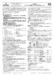
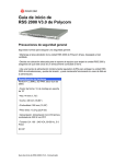
K50i Series
Technical Manual
K50F
K50P
K50F + K51S
03 April 2008
Version 1.01
M. Hume
Southern Office:
Raytel House
Brook Road
Rayleigh
Essex,
SS6 7XH
Tel: (01268) 749311
Fax: (01268) 749315
Northern Office:
20-23 Woodside Place,
Glasgow,
Strathclyde,
G3 7QF.
Tel:(0141) 5821275
CONTENTS
SYSTEM OVERVIEW
Key Features and Connectors ........................................................................... 3
Box Contents & Installation ............................................................................... 4
Specification..................................................................................................... 5
SYSTEM DIAGRAMS
Earth Connection .............................................................................................. 6
Fail Safe Lock Wiring and Programming ........................................................... 7
Fail Secure Lock Wiring and Programming ........................................................ 8
Fail Safe Lock Wiring and Programming with Keypad In/Out.............................. 9
Fail Secure Lock Wiring and Programming with Keypad In/Out ........................ 10
Wiring and Programming with Door Entry Systems .......................................... 11
Single Door Proximity with Fail Safe Lock Wiring and Programming ................. 12
Single Door Proximity with Fail Secure Lock Wiring and Programming ............. 13
Doorbell Function Wiring and Programming .................................................... 14
Alarm, Tamper and Door Contact Wiring and Programming ............................. 15
Lift Control Wiring and Programming............................................................... 16
Up to 254 Keypads Direct to PC....................................................................... 17
Up to 254x16 Keypads using 716E 16 Door Controller...................................... 18
Up to 254 Keypads Direct to PC with RS-485 Repeater .................................... 19
BASIC PROGRAMMING
Entering/Exiting Programming......................................................................... 20
Factory Reset, Changing Master Code and Lock Time ..................................... 20
Adding User Codes, Enabling RTE and Setting Latch Mode.............................. 21
Anti-Passback................................................................................................. 22
ADVANCED PROGRAMMING
Adding/Deleting Tokens .................................................................................. 23
Doorbell Function............................................................................................ 24
Alarm Functions.............................................................................................. 25
Lift Control...................................................................................................... 26
Setting AR-401RO16B DIP Switches ................................................................ 27
Auto-Open Zone Programming ........................................................................ 28
Programming Charts....................................................................................... 29
Resetting Master Code.................................................................................... 30
NETWORKING
Connecting Directly to a PC............................................................................. 31
Networking Under an AR-716E ........................................................................ 34
PROGRAMMING CHART .............................................................................. 35
TABLE OF USERS ......................................................................................... 36
2
RSSD K50P
SYSTEM OVERVIEW
Key Features
The K50P is a versatile Keypad capable of many functions and several different mounting
options.
Key Features:
•
Upto 1024 different 4 digit user codes
•
2 internal open time zones
•
Tamper Switch
•
32 floor lift control
•
Door Monitoring
•
Code in/Code out (with additional Wiegand Keypad)
•
Optional Anti-pass back function with Code In/Out
•
Egress Button
•
Network capability up to 254 x 16 doors each with Keypad In/Out
•
Duress Code
•
Optional Lock Outputs - Timed 0.1 to 600 seconds, Latched On/Latched Off
•
Universal Serial Port for LED Display, Printer, Lift Control etc.
•
Alarm function for Tamper, Forced Entry, Duress and Door Open
•
Will run as a Standalone Controller during Host Controller failure
•
Proximity Card flash edit mode
•
Buffer for up to 1200 Transactions
•
Auto-Relock Function
•
Real Time Clock
Connectors
P3
P1
P1
Table 1: Connector P1 colour coding.
Wire Application
Door Sensor
Exit Switch
Wire
1
2
3
4
5
Colour
Blue/White
Purple/White
White
Orange
Purple
Alarm Output
6
Grey
Power
7
8
Thick Red
Thick Black
Door Relay
P2
P2
Transistor Output
(Open Collector Active Low)
DC Power 12V
DC Power 0V
Table 2: Connector P2 colour coding.
Wire Application
Host Connection
Wiegand
Sounder
LED
P3
Description
(N.O.) DC24V 1A
(N.C.) DC 24V 1A
(COM) DC24V 1A
Negative Trigger Input
Negative Trigger Input
Wire
1
2
3
4
5
6
7
Colour
Thick Green
Thick Blue
Thin Blue
Thin Green
Pink
Brown
Yellow
Description
RS-485 (B-)
RS-485 (A+)
Wiegand DAT:1 Input
Wiegand DAT:0 Input
Sounder Output 5V/100mA, Low
Green LED Output 5V/20mA, Max
Red LED Output 5V/20mA, Max
Table 3: Tamper Switch Connector P3 colour coding.
Wire Application
Tamper Switch
Wire
1
2
3
Colour
Red
Orange
Yellow
Description
Normally Closed
Common
Normally Open
Contact Rating: 1A 125VAC/24VDC
RSSD K50P
3
SYSTEM OVERVIEW
Box Contents and Installation
K50P
A. Keypad
and Cover
B. Manual
C. Leads
D. Screws and
Torx Wrench
E. Gasket
A. Connect wires as required, see previous page.
B. Plug connectors into Keypad.
C. Screw Keypad to the wall.
D. Fit cover onto Keypad.
E. Apply power, Red LED will flash and sounder will beep.
F. Commence programming as required.
K50F
A. Keypad
B. Manual
C. Leads
D. Screws and
Torx Wrench
A. Fit backbox FB146 (supplied separately) into the wall.
B. Connect wires as required, see previous page.
C. Plug connectors into Keypad.
D. Screw Keypad to the backbox.
E. Apply power, Red LED will flash and sounder will beep.
F. Commence programming as required.
K50CS (K50F + K51S)
A. Keypad
and Shroud
B. Manual
C. Leads
D. Screws and
Torx Wrench
A. Screw K51S to the wall.
B. Connect wires as required, see previous page.
C. Plug connectors into Keypad.
D. Screw Keypad to the K51S.
E. Apply power, Red LED will flash and sounder will beep.
F. Commence programming as required.
WARNING
The communication and power cables should not be housed in
the same electrical conduit. They should always be installed in
separate conduit.
4
RSSD K50P
SYSTEM OVERVIEW
K50i Specification
Mode No.
M4
M6
M8
User Capacity
1,024
65,536
1,024
Event Log
1,200
N/A
1,200
5-Digit User
Address+ 4-Digit
Individual Password
4-Digit Public
Password
4-Digit Individual
Password
Access Mode
Support
Stand-Alone / Networking
Voltage
9-24 VDC
9-18 VAC
Power Requirement
Communication Interface
Baud Rate
<3W
RS-485
9600 bps (N, 8, 1)
Operating Temperature
-20°C ~ +75°C
DI Input
Egress Button
Door Sensor
DO Output
1 Door Relay Output
Transistor Output
Duress/Alarm/Arming LED
Door Relay Time
0, 0.1~600 sec.
Alarm Relay Time
0, 1~600 sec.
Tamper Resist. Switch
AntiAnti-Passback
Limit Switch (Form C)
Yes
Serial Out
TTL (4800 bps, N, 8, 1)
IP Rating
IP65
Real Time Clock
Yes
1 Bi-Colour LED
1 Piezo Sounder
Indicator
PBT Housing
Gray ABS Plastic
Metal Box
Brushed Stainless Steel
PBT only
113.75(L)x65.20(W)x28.20(H)
Metal Box
150(L)x92(W)x49.28(H)
Colour
Dimensions
(mm)
Housing Material
RSSD K50P
PBT Keypad Housing
Metal box: 316 Stainless Steel
5
6
RSSD K50P
RSSD K50P
7
RED
ORANGE
YELLOW
YELLOW
BROWN
PINK
GREEN
BLUE
THICK BLUE
THICK GREEN
BLUE/WHITE
PURPLE/WHITE
WHITE
ORANGE
PURPLE
GREY
RED
BLACK
CN2
CN1
PUSH TO MAKE
EXIT BUTTON
1
ISS
INIT IAL
DESCRIPTION
DATE
11 - 02 - 08
THE RAYTEL GROUP LTD
K50i bas ic connection diagram with fail s afe lock
TITLE
CHECKED
JJT
DRAWING No.
DRAWN
MH
RSS2000/79
APPROVED
JJT
A Diode MUST Be Fitted
To The Lock As Shown
IMPORTANT.
12V FAIL SAFE LOCK
-
+
Please note that all drawings and diagrams supplied for bespoke applications for RSS products are given as a free service to assist customers and no liability for errors and ommissions can be accepted by RSS. Customers remain entirely responsible for the quality and correctness of all installation work.
CN3
- +
TO 12V PSU
11 - 02 - 08
DATE
8
RSSD K50P
RED
ORANGE
YELLOW
YELLOW
BROWN
PINK
GREEN
BLUE
THICK BLUE
THICK GREEN
BLUE/WHITE
PURPLE/WHITE
WHITE
ORANGE
PURPLE
GREY
RED
BLACK
CN2
CN1
PUSH TO MAKE
EXIT BUTTON
DESCRIPTION
INIT IAL
ISS
1
DATE
11 - 02 - 08
THE RAYTEL GROUP LTD
K50i bas ic connection diagram with fail s ecure lock
TITLE
JJT
CHECKED
DRAWING No.
DRAWN
MH
RSS2000/80
APPROVED
JJT
A Diode MUST Be Fitted
To The Lock As Shown
IMPORTANT.
11 - 02 - 08
DATE
12V FAIL SECURE LOCK
-
+
Please note that all drawings and diagrams supplied for bespoke applications for RSS products are given as a free service to assist customers and no liability for errors and ommissions can be accepted by RSS. Customers remain entirely responsible for the quality and correctness of all installation work.
CN3
- +
TO 12V PSU
RSSD K50P
9
YELLOW
ORANGE
RED
ORANGE
GREEN
BLUE
YELLOW
BROWN
PINK
RED
BLACK
CN2
CN1
CN3
RED
ORANGE
YELLOW
YELLOW
BROWN
PINK
GREEN
BLUE
T HICK BLUE
T HICK GREEN
BLUE/WHIT E
PURPLE/WHIT E
WHIT E
ORANGE
PURPLE
GREY
RED
BLACK
CN2
CN1
1
ISS
INIT IAL
DESCRIPTION
DATE
11 - 02 - 08
THE RAYTEL GROUP LTD
TITLE
K50i connection diagram with keypad in/out
and fail s afe lock
JJT
CHECKED
DRAWING No.
DRAWN
MH
RSS2000/81
APPROVED
JJT
A Diode MUST Be Fitted
To The Lock As Shown
IMPORTANT.
12V FAIL SAFE LOCK
-
+
Please note that all drawings and diagrams supplied for bespoke applications for RSS products are given as a free service to assist customers and no liability for errors and ommissions can be accepted by RSS. Customers remain entirely responsible for the quality and correctness of all installation work.
CN3
AR-721K
- +
TO 12V PSU
11 - 02 - 08
DATE
10
RSSD K50P
YELLOW
ORANGE
RED
ORANGE
GREEN
BLUE
YELLOW
BROWN
PINK
RED
BLACK
CN2
CN1
CN3
RED
ORANGE
YELLOW
YELLOW
BROWN
PINK
GREEN
BLUE
T HICK BLUE
T HICK GREEN
BLUE/WHIT E
PURPLE/WHIT E
WHIT E
ORANGE
PURPLE
GREY
RED
BLACK
CN2
CN1
DESCRIPTION
INIT IAL
ISS
1
DATE
11 - 02 - 08
THE RAYTEL GROUP LTD
TITLE
K50i connection diagram with keypad in/out
and fail s ecure lock
CHECKED
JJT
DRAWING No.
DRAWN
MH
RSS2000/82
APPROVED
JJT
A Diode MUST Be Fitted
To The Lock As Shown
IMPORTANT.
12V FAIL SECURE LOCK
-
+
Please note that all drawings and diagrams supplied for bespoke applications for RSS products are given as a free service to assist customers and no liability for errors and ommissions can be accepted by RSS. Customers remain entirely responsible for the quality and correctness of all installation work.
CN3
AR-721K
- +
TO 12V PSU
11 - 02 - 08
DATE
RSSD K50P
11
RED
ORANGE
YELLOW
YELLOW
BROWN
PINK
GREEN
BLUE
THICK BLUE
THICK GREEN
BLUE/WHITE
PURPLE/WHITE
WHITE
ORANGE
PURPLE
GREY
RED
BLACK
CN2
CN1
PUSH TO MAKE
EXIT BUTTON
9-12V
NO
AR-821RB-18 13-18V
C
RELAY
NC
0V
DESCRIPTION
INIT IAL
ISS
1
DATE
11 - 02 - 08
THE RAYTEL GROUP LTD
K50i connection diagram with door entry s ys tem
TITLE
CHECKED
JJT
DRAWING No.
DRAWN
MH
RSS2000/83
APPROVED
JJT
11 - 02 - 08
DATE
To lock release output
on Door Entry System
To terminal 15 on
Power Supply
A Diode MUST Be Fitted
To The Lock As Shown
IMPORTANT.
12V FAIL SAFE LOCK
-
+
12V FAIL SECURE LOCK
-
+
Please note that all drawings and diagrams supplied for bespoke applications for RSS products are given as a free service to assist customers and no liability for errors and ommissions can be accepted by RSS. Customers remain entirely responsible for the quality and correctness of all installation work.
CN3
- +
TO 12V PSU
12
RSSD K50P
A Diode MUST Be Fitted
To The Lock As Shown
IMPORTANT.
RSSD K50P
13
A Diode MUST Be Fitted
To The Lock As Shown
IMPORTANT.
14
RSSD K50P
RED
ORANGE
YELLOW
YELLOW
BROWN
PINK
GREEN
BLUE
THICK BLUE
THICK GREEN
BLUE/WHITE
PURPLE/WHITE
WHITE
ORANGE
PURPLE
GREY
RED
BLACK
CN2
CN1
NO
AR-821RB-18
C
RELAY
0V
NC
9-12V
13-18V
V-
+12V
DESCRIPTION
INIT IAL
ISS
1
11 - 02 - 08
DATE
THE RAYTEL GROUP LTD
K50i connection diagram for doorbell function
TITLE
CHECKED
JJT
DRAWING No.
DRAWN
MH
APPROVED
JJT
RSS2000/103
Please note that all drawings and diagrams supplied for bespoke applications for RSS products are given as a free service to assist customers and no liability for errors and ommissions can be accepted by RSS. Customers remain entirely responsible for the quality and correctness of all installation work.
CN3
- +
TO 12V PSU
11 - 02 - 08
DATE
RSSD K50P
15
RED
ORANGE
YELLOW
YELLOW
BROWN
PINK
GREEN
BLUE
THICK BLUE
THICK GREEN
BLUE/WHITE
PURPLE/WHITE
WHITE
ORANGE
PURPLE
GREY
RED
BLACK
CN2
CN1
"Normally Closed"
Magnetic Door Contacts
DESCRIPTION
INIT IAL
ISS
1
DATE
11 - 02 - 08
THE RAYTEL GROUP LTD
TITLE
K50i connection diagram for alarm ,
tam per and door contacts
CHECKED
JJT
DRAWING No.
DRAWN
MH
RSS2000/86
APPROVED
JJT
NO
AR-821RB-18
13-18V
C
RELAY
0V
NC
9-12V
Please note that all drawings and diagrams supplied for bespoke applications for RSS products are given as a free service to assist customers and no liability for errors and ommissions can be accepted by RSS. Customers remain entirely responsible for the quality and correctness of all installation work.
V-
+12V
CN3
- +
TO 12V PSU
11 - 02 - 08
DATE
16
RSSD K50P
AR-829L485
RED
BLACK
ORANGE AND WHITE
NOT CONNECTED
YELLOW
CN3
GREY
RED
ORANGE
YELLOW
K50i
YELLOW
BROWN
PINK
GREEN
BLUE
THICK BLUE
THICK GREEN
BLUE/WHITE
PURPLE/WHITE
WHITE
ORANGE
PURPLE
GREY
RED
BLACK
CN2
CN1
DESCRIPTION
INIT IAL
ISS
1
11 - 02 - 08
DATE
THE RAYTEL GROUP LTD
TITLE
K50i Connection diagram for
lift control
CHECKED
DRAWING No.
DRAWN
MH
APPROVED
RSS2000/90
Please note that all drawings and diagrams supplied for bespoke applications for RSS products are given as a free service to assist customers and no liability for errors and ommissions can be accepted by RSS. Customers remain entirely responsible for the quality and correctness of all installation work.
AR-401R
12V 0V A+ B-
GREEN
BLUE
12v 0v
12V PSU
11 - 02 - 08
DATE
RSSD K50P
CN3
RED
ORANGE
YELLOW
RS232
Red
Blue
Green
YELLOW
BROWN
PINK
GREEN
BLUE
THICK BLUE
THICK GREEN
BLUE/WHITE
PURPLE/WHITE
WHITE
ORANGE
PURPLE
GREY
RED
BLACK
CN2
CN1
TWISTED PAIR
RS485
Black
- +
TO 12V PSU
CN3
RED
ORANGE
YELLOW
YELLOW
BROWN
PINK
GREEN
BLUE
THICK BLUE
THICK GREEN
BLUE/WHITE
PURPLE/WHITE
WHITE
ORANGE
PURPLE
GREY
RED
BLACK
TWISTED PAIR
CN2
CN1
- +
TO 12V PSU
DESCRIPTION
INIT IAL
ISS
1
11 - 02 - 08
DATE
THE RAYTEL GROUP LTD
TITLE
K50i connection diagram for up to
254 keypads direct to PC
17
CHECKED
JJT
DRAWING No.
DRAWN
MH
APPROVED
JJT
11 - 02 - 08
DATE
TO NEXT K50i
TWISTED PAIR
RSS2000/87
Please note that all drawings and diagrams supplied for bespoke applications for RSS products are given as a free service to assist customers and no liability for errors and ommissions can be accepted by RSS. Customers remain entirely responsible for the quality and correctness of all installation work.
P.C.
AR-701CM
18
RSSD K50P
Green
Blue
Black
Red
12v 0v
12V PSU
+
A+
B-
HOST
AR-716E
CH1
CH2
+
+
-
+
-
BLACK
To 12V PSU
-
+
To 12V PSU
RED
BLACK
To 12V PSU
+ -
BLACK
RED
THICK THICK
BLUE GREEN
K50i
THICK
GREEN
K50i
THICK
BLUE
RED
K50i
THICK THICK
BLUE GREEN
THICK THICK
BLUE GREEN
K50i
BLACK
BLACK
-
BLACK
To 12V PSU
+
RED
K50i
THICK THICK
BLUE GREEN
THICK THICK
BLUE GREEN
K50i
RED
+ -
+ -
RED
To 12V PSU
To 12V PSU
TWISTED PAIR
K50i
THICK THICK
BLUE GREEN
K50i
BLACK
RED
THICK THICK
BLUE GREEN
BLACK
RED
-
+
To 12V PSU
BLACK
-
BLACK
To 12V PSU
+ -
RED
K50i
THICK THICK
BLUE GREEN
THICK THICK
BLUE GREEN
K50i
RED
+
To 12V PSU
BLACK
-
THICK
GREEN
-
BLACK
To 12V PSU
+
RED
K50i
THICK THICK
BLUE GREEN
THICK
BLUE
K50i
RED
+
To 12V PSU
BLACK
-
-
BLACK
To 12V PSU
+
RED
K50i
THICK THICK
BLUE GREEN
THICK THICK
BLUE GREEN
K50i
RED
+
To 12V PSU
DESCRIPTION
INIT IAL
ISS
1
DATE
11 - 02 - 08
THE RAYTEL GROUP LTD
TITLE
K50i connection diagram for up to 254x16
keypads us ing 716E 16 door controller
JJT
CHECKED
DRAWING No.
DRAWN
MH
BLACK
-
BLACK
RSS2000/89
APPROVED
JJT
To 12V PSU
+ -
RED
K50i
THICK THICK
BLUE GREEN
THICK THICK
BLUE GREEN
K50i
RED
+
To 12V PSU
Please note that all drawings and diagrams supplied for bespoke applications for RSS products are given as a free service to assist customers and no liability for errors and ommissions can be accepted by RSS. Customers remain entirely responsible for the quality and correctness of all installation work.
To Next AR-716E
TWISTED PAIR
RS485
AR-701CM
RS232
P.C.
-
+
To 12V PSU
11 - 02 - 08
DATE
RSSD K50P
Black
Red
Green
Blue
KEYPADS 1 - 32
TWISTED PAIR
GREEN
BLUE
0V
+12V
+
DATA IN
DATA OUT
AR-485REP
+
-
BLUE
GREEN
TWISTED PAIR
KEYPADS 33 - 64
TWISTED PAIR
DESCRIPTION
INIT IAL
ISS
1
DATE
11 - 02 - 08
THE RAYTEL GROUP LTD
K50i connection diagram for up to 254 keypads
direct to PC with 485 repeater
TITLE
CHECKED
JJT
DRAWING No.
DRAWN
MH
BLUE
RSS2000/88
APPROVED
JJT
GREEN
Please note that all drawings and diagrams supplied for bespoke applications for RSS products are given as a free service to assist customers and no liability for errors and ommissions can be accepted by RSS. Customers remain entirely responsible for the quality and correctness of all installation work.
RS485
AR-701CM
RS232
P.C.
12v 0v
12V PSU
11 - 02 - 08
DATE
TO NEXT
AR-485REP &
NEXT 32
KEYPADS
ADDITIONAL CONNECTION
CONNECTION DIAGRAM
19
BASIC PROGRAMMING
Entering and Exiting Programming Mode
To Enter Programming Mode Master Code # ( 123456 # default code)
To Exit Programming Mode #
Factory Reset, Changing Master Code & Lock Time
1. Restoring Factory Settings
To Reset Keypad 20 000 # 15 0000 # 24 000 # 26 00000 01023 2 # 28 000 # 29 29 # #
2. Changing the Master Code
To Change Master Code 09 Enter New Master Code Twice #
4. Changing the Lock Time
To Change Lock Time 02 3-Digit Lock Time in Seconds #
3. Changing the Control Mode
To Change Control Mode 04 4, 6 or 8 #
Enter 4 For Control Mode 4
Enter 6 For Control Mode 6
Enter 8 For Control Mode 8
See below.
Mode
M4
M6
M8
Stand-Alone
Networking
Stand-Alone
Stand-Alone
Networking
1024
1
1024
9-Digit Individual
Code
4-Digit Common
Code
4-Digit Individual
Code
1200
N/A
1200
Holiday Function
Yes
No
Yes
Duress
Yes
No
Yes
Time Zone
11
N/A
11
Lift Control
32
N/A
32
Anti-Passback
Yes
N/A
Yes
Application
System
Code Capacity
Access Mode
Event Capacity
NOTICE
Most applications require the Keypad to be set up in Mode 8.
20
RSSD K50P
BASIC PROGRAMMING
Adding User Codes, Enabling RTE and Latch Mode
1. Adding Individual User Codes
To Add Individual User Codes in Mode 8 12 User Address 4-Digit Code #
2. Adding a Common Code
To Add a Common Code in Modes 4 and 6 15 4-Digit Common Code #
3. Setting the Lock to Latch Mode
To Set Latch Mode 02 000 #
4. Enabling Exit Function
To Enable Exit Function 20 016 #
5. Deleting Individual User Codes
To Delete Individual User Codes 10 Start Address End Address #
NOTICE
Refer to Chart A 20DDD# on page 29 for the values needed for
programming the Exit Function.
RSSD K50P
21
BASIC PROGRAMMING
Anti-Passback
1. Enabling AntiAnti-Passback (Optional)
To Enable Anti-Passback 20*128#
2. Enable User For AntiAnti-Passback (Optional)
To Enable Users for Anti-Passback
26 Start Address End Address 0 = Enable or 1 = Disable #
NOTICE
Refer to Chart A 20DDD# on page 29 for the values needed for
programming Anti-Passback.
22
RSSD K50P
ADVANCED PROGRAMMING
Adding/Deleting Tokens
1. Adding a Single/Multiple Non Sequential Random Token
To Add Single/Non Sequential Token 19 User Address Token Quantity #
Present Token to Reader.
When adding multiple tokens the User Address will automatically increase with each Token.
2. Adding Multiple Sequential Tokens
To Add Multiple Sequential Tokens 19 User Address Token Quantity #
Present Lowest Numbered Token to Reader.
3. Deleting Tokens
To Delete Tokens 10 Start User Address End User Address #
3. Suspending Tokens
To Suspend Tokens 10 Start User Address 9 End User Address #
Example
Deleting a Single Token
Enter Programming Mode Master Code # 10 00001 9 00001 # #
(00001 = Start User Address, 00001 = End User Address)
Token 00001 has been Deleted.
Suspending Multiple Tokens
Enter Programming Mode Master Code # 10 00001 00010 # #
(00001 = Start User Address, 00010 = End User Address)
Tokens 00001 - 00010 have been Suspended.
NOTICE
Refer to Table of Users for User details before deleting Tokens.
RSSD K50P
23
ADVANCED PROGRAMMING
Doorbell Function
2. Enabling Doorbell Function
To Enable Doorbell Function 24 128 #
24DDD#
OPTION
FUNCTION
VALUE
APPLICATION
Enable
001
Networking/
Stand-Alone
Alarm Output †
Lift Control
002
Networking/
Stand-Alone
Stop Alarm By...
None †
Push Button/
Door Closed
064
Networking/
Stand-Alone
Door Bell
Disable †
Enabled
128
Networking/
Stand-Alone
0
1
Auto-Open Door Without
Presenting Card at Auto Open
Zone
Disable †
Alarm Output/Lift Control
† = Default Setting
Example
To enable Auto-Open Door , Alarm Output and Doorbell, add the values of these functions
together:- Auto-Open Door = 001
Doorbell
= 128
Total
= 129
Enter Programming Mode 123456 # 24 129 # #
(129 is the sum of the required values for programming)
NOTICE
Refer to the charts on page 29 for full Programming Values.
WARNING
Enabling the Doorbell function will disable the Door Monitor
Alarm function.
24
RSSD K50P
ADVANCED PROGRAMMING
Alarm Functions
2. Enabling Alarm Output Function
To Enable Alarm Output 24 000 #
3. Enabling Stop Alarm By...
To Enable Stop Alarm By… 24 064 #
4. Enabling Auto Relock
To Enable Auto Relock 20 002 #
5. Enabling Force Open Alarm Output
To Enable Force Open Alarm Output 28 128 #
6. Changing Alarm Relay Time
To Change Alarm Relay Time 03 3-Digit Alarm Relay Time in Seconds #
7. Changing Alarm Delay Time
To Change Alarm Delay Time 06 3-Digit Alarm Delay Time in Seconds #
NOTICE
Refer to the charts on page 29 for full Programming Values.
RSSD K50P
25
ADVANCED PROGRAMMING
Enabling Lift Control & Setting Relay Time
1. Enabling Lift Control Function
To Enable Lift Control Function 24 002 #
2. Setting Relay Time
To Set Relay Time 23 Node ID of Lift Controller 3-Digit Relay Time in Seconds #
Optional Floor Access Programming
3a. Single Floor Programming
To Program Single Floors 27 User Address Floor Number 01 - 32 #
3b. Multiple Floor Programming
To Program Multiple Floors 21 User Address Lift Set 1 - 4 7-Digit Floor Number #
Examples
4. Single Floor Programming
Enter Programming Mode MASTER CODE # 27 00001 07 # #
(00001 = User Address, 07 = Floor Number 01 - 32)
User 00001 is programmed for access to floor 07
5. Multiple Floor Programming
Enter Programming Mode MASTER CODE # 21 00001 3 00001111 #
(00001 = User Address, 3 = Floors 25 - 32 & 00001111 = Floor Numbers 28 - 25) #
00000001 = Floors 1, 9, 17 & 25
00000010 = Floors 2, 10, 18 & 26
00000100 = Floors 3, 11, 19 & 27
00001000 = Floors 4, 12, 20 & 28
00010000 = Floors 5, 13, 21 & 29
00100000 = Floors 6, 14, 22 & 30
01000000 = Floors 7, 15, 23 & 31
10000000 = Floors 8, 16, 24 & 32
Floor/Stop
Set
F
F
F
F
F
F
F
F
0
8
7
6
5
4
3
2
1
1
16
15
14
13
12
11
10
9
2
24
23
22
21
20
19
18
17
3
32
31
30
29
28
27
26
25
NOTICE
When Programming Floors, follow the parameters for either Single Floor or
Multiple Floors, NOT both.
Refer to Chart 24 DDD # on page 29 for all of the values needed for
programming and ensure ALL Users have been added.
26
RSSD K50P
ADVANCED PROGRAMMING
Setting AR401-RO16B DIP Switches
Default DIP Switch settings on the AR-401RO16B are as follows:ID Number
Baud Rate
N/A Relay
Floor Access is determined by the Node ID, which is set by Dip Switches 1 to 4. The Node ID
of the AR-401RO16 must be set up to one of the following numbers.
ID 1
ID 2
ID 3
ID 4
ID 5
ID 1 = Floors 1 - 16
ID 2 = Floors 17 - 32
ID 3 = Generally Not Used
ID 4 = Floors 33 - 48
ID 5 = Floors 49 - 64
The Baud Rate is the communication speed between the AR-401RO16 and the associated
access controller. The Baud Rate must be set to 4800 (Switches 5 on and 6 off).
All Relay outputs can be set so all Relays are Normally Open or Normally Closed via the DIP
Switch. DIP Switch 8 sets the state of all the Relays, in addition individual Relays can be set
to Normally Open or Normally Closed separately via the Jumpers on each relay circuit.
N.C.
N.O.
N.C. = Switch 8 on
N.O. = Switch 8 off
Jumper J10 set to
Normally Open
Jumper J10 set to
Normally Open
Jumper J9 set to
Normally Closed
(Default Setting)
Jumper J9 set to
Normally Closed
(Default Setting)
The default setting is with the Switch set to N.C. and the Jumpers set to NC. In this mode the
Relays are normally open and normally closed when operated.
Alternative settings are:With the Switch set to N.C. and the Jumpers set to NO, the Relays are closed going open.
With the Switch set to N.O. and the Jumpers set to NC, the Relays are closed going open.
With the Switch set to N.O. and the Jumpers set to NO, the Relays are open going closed.
RSSD K50P
27
ADVANCED PROGRAMMING
Auto-Open Zone Programming
1. Enable/Disable AutoAuto-Open Zone
To Enable/Disable Auto-Open Zone 20 004 #
(Refer to Chart 20*DDD# below for additional function values)
2. Enable/Disable AutoAuto-Open Zone without Presenting a Token
To Enable/Disable Auto-Open Zone without Presenting a Token 24 001 #
(Refer to Chart 24*DDD# on page 23 for additional function values)
3. Open Time Setup
To Set Auto-Open Zones 08 Auto-Open Zone Start Time & End Time Days #
When Setting Days, 1 = Enable 0 = Disable)
20 DDD #
OPTION
FUNCTION
VALUE
APPLICATION
No
001
Networking
Disable †
Enable
002
Networking/
Stand-Alone
Auto Open
Disable †
Enable
004
Networking/
Stand-Alone
Exit by Push Button
Disable †
Enable
016
Networking/
Stand-Alone
Master Reader of Network
Slave †
Master
032
Networking
Access/Exit Reader
Exit †
Access
064
Networking
Anti-Passback
Disable †
Enable
128
Networking
0
1
Time Attendance
Yes †
Auto Relock
Example
1. Enable/Disable AutoAuto-Open Zone without Presenting a Token
Enter Programming Mode MASTER CODE # 24 001 # 08 1 08301000 0111110 # #
24 001 # = Auto-Open Zone enabled, refer to page 23 for details.
08 ... 1 = Second Auto-Open Zone enabled
08301000 = Auto-Open Time set from 0830 to 1000
0111110 = Mon - Fri set .
28
RSSD K50P
LIFT CONTROL AND ALARM
ALARM PROGRAMMING CHARTS
20 DDD #
OPTION
FUNCTION
VALUE
APPLICATION
No
001
Networking
Disable †
Enable
002
Networking/
Stand-Alone
Auto Open
Disable †
Enable
004
Networking/
Stand-Alone
Exit by Push Button
Disable †
Enable
016
Networking/
Stand-Alone
Master Reader of Network
Slave †
Master
032
Networking
Access/Exit Reader
Exit †
Access
064
Networking
Anti-Passback
Disable †
Enable
128
Networking
VALUE
APPLICATION
0
1
Time Attendance
Yes †
Auto Relock
† = Default Setting
24 DDD #
OPTION
FUNCTION
0
1
Auto-Open Door Without
Presenting Card at Auto Open
Zone
Disable †
Enable
001
Networking/
Stand-Alone
Alarm Output/Lift Control
Alarm Output †
Lift Control
002
Networking/
Stand-Alone
Stop Alarm By...
None †
Push Button/
Door Closed
064
Networking/
Stand-Alone
Door Bell
Disable †
Enable
128
Networking/
Stand-Alone
VALUE
APPLICATION
† = Default Setting
28 DDD #
OPTION
FUNCTION
0
1
Two Door Opening
Disable †
Enable
064
Networking/
Stand-Alone
Force Open Alarm Output
Disable †
Enable
128
Networking/
Stand-Alone
† = Default Setting
RSSD K50P
29
ADVANCED PROGRAMMING
Resetting Master Code
The Master Code can only be reset by connecting to a PC or laptop with the Soyal Access
Control Software installed as follows:Connect the keypad to the PC using an AR-701CM RS-232/RS-485 Converter or an
AR-321CM USB/RS-485 Converter.
+12VDC
TO PC
0V
Thick Green
Thick Blue
TO PC
Open ISP Tools
Thick Blue
Thick Green
the following window will open.
1
2
4
3
1 Select “AR721H/W,757,RAY737,401DIO,725U,721_SIM(EM/MIF)”
2 Set the correct Node Number (Default 1)
3 Select the correct COM Port
4 Click “Reset Master Code (72xH)” button
The Master Code is now reset to the default setting of 123456 #
NOTICE
For full software installation instructions and details of COM port number,
please refer to the AR-321 Driver, Soyal Device Tools, 701 Server & 701
Client Installation and Setup Manual, which can be found in the downloads
section of our website or by following the link below.
http://www.raytelsecurity.co.uk/downloads/Soyal%20Driver%20and%20Software%20Installation%20and%20Setup%20Manual.pdf
30
RSSD K50P
NETWORKING
Connecting Directly to a PC
1. Setting Node ID
To Set Node ID 00 Keypad Node ID Virtual 716E Node ID Door Number #
Example
Enter Programming Mode MASTER CODE # 00 001 001 001 # #
Setting up the Keypad with 701 Server Software is performed as follows:Right click on “My Computer” on the desktop, or click on “Start” then right click on “My
Computer”
Click on “Properties”
Click on “Hardware”
Click on “Device Manager”
Click on “+” next to “Ports (COM & LPT)”
“Prolific USB-to-Serial Comm Port (COM?)”
Will show the COM Port the USB converter
is connected to.
Continued Over
RSSD K50P
31
NETWORKING
Connecting Directly to a PC Continued
Right click on 701 Server icon on the toolbar and click Run
Login to 701 Server, default password and user name are both supervisor.
Click on button 1, Com
Select the following (see below):Select COM Port
Tick Polling Message From Controller
Set Polling Interval to 200ms
Click Yes
1
4
2
3
Click on button 2, LAN
Continued Over
32
RSSD K50P
NETWORKING
Connecting Directly to a PC Continued
Select the following (see below):Tick Keypad Node ID
Select 721E
Set LAN BASE to AR-7xx/8xxE
Set Node Range to 000-007
Click Yes
1
2
3
4
5
Click on button 3, Line
Click on the box marked +
The Keypad will now be online, indicated
by a white Y in a blue disc
The Keypad is now online and ready to program.
NOTICE
Refer to the 701 Client and 701 Server manuals for programming
information. Refer to Additional Connection Diagram on page 19
for details on connecting AR-485REP RS485 repeaters if
connecting more than 32 Networked Keypads.
RSSD K50P
33
NETWORKING
Networking Under an AR-716E
1. Setting Node ID
To Set Node ID 00 Node ID of Keypad #
Example
1. Setting Node ID
To Set Node ID Enter Programming Mode MASTER CODE # 00 001 # #
NOTICE
Refer to the AR-716E manual and 701 Client and 701 Server
manuals for further programming information.
Refer to Additional Connection Diagram on page 19 for details on
connecting AR-485REP RS485 repeaters if connecting more than
32 Networked Keypads.
34
RSSD K50P
PROGRAMMING TABLE
Command List
Function
Control
Mode
Command
Entering Programming Mode
123456 # or Master Code # (If Already Changed)
M4/6/8
Exiting Programming Mode
#
M4/6/8
Exiting Programming Mode
and Enabling Arming Status
#
M4/6/8
Node ID Setting Connected to
716E For More Than 254 Units
00 NNN # (NNN = Node ID: 001 – 254)
M4/8
Node ID Setting Connected
To PC For Up to 254 Units
00 NNN VVV nnn # (NNN = Node ID of K50i, VVV = Virtual 716E Node
ID, nnn = Door Number)
M4/8
Arming Relay Time Setting
02 TTT # (TTT = Lock Relay Time,000 = Toggle, 001 – 600 = 1 – 600 Sec,
601 – 609 = 0.1 – 0.9 Sec)
03 TTT # (TTT = Door Relay Time, 000 = Toggle, 001 – 600 = 1 – 600 Sec)
Control Mode Setting
04 N # (N = Mode 4/6/8)
M4/6/8
Arming Delay Time Setting
05 TTT # (TTT = Arming Delay Time, 001 – 600 = 1 – 600 Sec)
M4/6/8
Alarm Delay Time Setting
06 TTT # (TTT = Arming Delay Time, 001 – 600 = 1 – 600 Sec)
M4/6/8
Auto-Open Zone Setting
08 N HHMMHHMM 1111111 # (N = 2 Sets of Auto Open Zone,
HHMMHHMM = Start Time to End Time, 1111111 = Days S/M/T/W/T/F/S 0 = Disable, 1 = Enable)
M4/6/8
Master Code Setting
09 PPPPPPRRRRRR # (PPPPPP = Master code, RRRRRR = Repeat
Master Code)
M4/6/8
Lock Relay Time Setting
Deleting Tokens/User Codes
Arming Output Time Setting
10 SSSSS EEEEE # (SSSSS = Start Address, EEEEE = End Address)
12 UUUUU PPPP # (UUUUU = User Address, PPPP = 4 – Digit User
Code)
14 TTT # (TTT = Arming Output Time, 001 – 250 = 1 – 250 Sec)
Duress Code Setting (M4/M8)
Common Code Setting (M6)
15 PPPP # (PPPP = 4 Digit Duress Code)
15 PPPP # (PPPP = 4 – Digit Common Code - Set to 0000 to disable)
Setting PWD/PIN
Door Close Time
Adding Tokens
M4/6/8
M4/6/8
M4/6/8
M4/6/8
M4/6/8
M4/8
M6
18 TTT # (TTT = Door Close Time, 001 – 600 = 1 – 600 Sec, Default = 15
Sec)
19 UUUUU QQQQQ # (UUUUU = User Address, QQQQQ = Token
Quantity)
M4/6/8
M4/6/8
Factory Setting 1
20 DDD # (DDD – Refer to Chart A 20*DDD# on Page 29 for Details)
M4/6/8
Lift Control Setting:
Multi Doors
21 UUUUU S FFFFFFFF # (UUUUU = User Address, S & F - Refer to
Charts on Page 25 for Details)
M4/6/8
Relay Time Of Lift Controller
Setting
23 NNN TTT # (NNN = Node ID, TTT = Relay Time, 001 – 600 = 1 – 600
Sec)
M4/6/8
Factory Setting 2
24 DDD # (DDD – Refer to Chart B 24*DDD# on Page 29 for Details)
M4/6/8
Real Time Clock Setting
(Stand-Alone)
25 YYMMDDHHmmss # (YYMMDDHHmmss = Year/Month/Day/Hour/
Minute/Second)
M4/6/8
Anti-Passback (Enable User)
26 SSSSS EEEEE # (SSSSS = Start Address, EEEEE = End Address)
M4/6/8
27 UUUUU FF # (UUUUU = User Address, FF = Floor Number 01 – 32)
M4/6/8
28 NNN # (NNN – Refer to Chart C 28*NNN# on Page 29 For Details)
M4/6/8
29 29 # followed by #
M4/6/8
Lift Control Setting (Single
Door)
Force Open Alarm Setting
Delete All Users
RSSD K50P
35
TABLE OF USERS
Name of On-Site Programmer(s): _
Installation Company: _
DEFAULT MASTER CODE:- 123456 #
USER MASTER CODE: _
User Address
Users Name
Tel: _
Date: _
Lock Time:_
Lock Type: _
Card ID
;
;
User Code
Date
;
;
;
;
;
;
;
;
;
;
;
;
;
;
;
;
;
;
;
;
;
;
;
;
;
;
;
;
;
;
;
;
;
;
;
;
;
;
;
;
;
;
;
;
;
;
;
;
We recommend this page should be filled in and regularly updated and kept in a safe and secure location by the person responsible for the upkeep of the system.