1
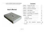
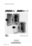
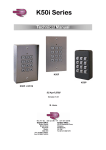
DC7000 Data Collection
Terminal
Hardware Manual
FCC Warning:
Note: This equipment has been tested and found to comply with the limits for a Class
A digital device, pursuant to Part 15 of the FCC rules. These limits are designed to
provide reasonable protection against harmful interference when the equipment is
operated in a commercial environment. This equipment generates, uses, and can
radiate radio frequency energy and, if not installed and used in accordance with the
instruction manual, may cause harmful interference to radio communications.
Operation of this equipment in a residential area is likely to cause harmful
interference in which case the user will be required to correct the interference at his or
her own expense.
Caution: Changes or modifications not expressly approved by the party
responsible for compliance could void the user’s authority to operate the
equipment.
FCC Compliance: (on hardware equipped with modem)
This equipment complies with Part 68 of FCC Rules and the requirements adopted by
the ACTA. On the rear housing of this equipment is a label that contains, among other
information, a product identifier in the format US:AAEQ##TXXXX. If requested
this number must be provided to the telephone company.
This product uses USOC modular telephone jack: R-J11C
A plug and jack used to connect this equipment to the premises wiring and telephone
network must comply with the applicable FCC Part 68 rules and requirements adopted
by the ACTA. A compliant telephone cord and modular plug is provided with this
product. It is designed to be connected to a compatible modular jack that is also
compliant. See installation instructions for details.
The REN is used to determine the number of devices that may be connected to a
telephone line. Excessive RENs on a telephone line may result in the devices not
ringing in response to an incoming call. In most but not all areas, the sum of RENs
should not exceed five (5.0). To be certain of the number of devices that may be
connected to a line, as determined by the total RENs, contact the local telephone
company. For products approved after July 23, 2001, the REN for this product is part
of the product identifier that has the format US:AAEQ##TXXX. The digits
represented by ## are the REN without the decimal point (e.g., 03 is a REN of 0.3).
For earlier products, the REN is separately shown on the label.
If this equipment, 4G3MM00B1011, causes harm to the telephone network, the
telephone company will notify you in advance that temporary discontinuance of
service may be required. But if advance notice isn’t practical, the telephone
company will notify the customer as soon as possible. Also, you will be advised of
your right to file a complaint with the FCC if you believe it is necessary.
2
The telephone company may make changes in its facilities, equipment, operations or
procedures that could affect the operation of the equipment. If this happens the
telephone company will provide advance notice in order for you to make necessary
modifications to maintain uninterrupted service.
If trouble is experienced with this equipment, 4G3MM00B1011, for repair or
warranty information please contact Acroprint Time Recorder Co. at 800-334-7190.
If the equipment is causing harm to the telephone network, the telephone company
may request you disconnect the equipment until the problem is resolved.
This equipment is of a type that is not intended to be repaired. For service contact
Acroprint Time Recorder Co. at 800-334-7190.
Connection to party line service is subject to state tariffs. Contact the state public
utility commission, public service commission or corporation commission for
information.
If you have specially wired alarm equipment connected to the telephone line, ensure
the installation of this 4G3MM00B1011 does not disable your alarm equipment. If
you have questions about what will disable alarm equipment, consult your telephone
company or a qualified installer.
Canada
This Class A digital apparatus complies with Canadian ICES-003. Cet appareil
numerique de la classe A est conforme a la norme NMB-003 Du Canada.
Lithium Battery Caution:
The circuit board on this terminal is populated with a lithium battery to protect data or
programs stored in the Random Access Memory (RAM). Do not, under any
circumstances, attempt to replace the lithium battery in the terminal. Failure to
comply may invalidate your warranty. Battery replacement should be done by
qualified personnel wearing the proper eye protection.
CAUTION: Danger of explosion if the battery is incorrectly replaced. Replace only
with the same or equivalent type recommended by the manufacturer. Discard used
batteries according to the manufacturer’s instruction.
This product utilizes a battery that contains Perchlorate Material.
Perchlorate Material – special handling may apply, See
www.dtsc.ca.gov/hazardouswaste/perchlorate
3
Declaration Of Conformity According To EMC Directive 89/336/EEC
We declare under our sole responsibility that the DC7000 magnetic stripe and/or
barcode reading and/or data recording equipment to which this declaration relates are
in conformity with the following standards: EN61000-6-1, EN55022-1998 with
Amendment A1: 2000(CISPR-22). I, the undersigned, hereby declare that the
equipment specified above conforms to the above directive and standards.
Raleigh, North Carolina
USA
May 22, 2006
All Rights Reserved. © COPYRIGHT 2006
Acroprint Time Recorder Company
4
W. Glenn Robbins
Table of Contents
1. Introduction .................................................................................. 6
Basic Hardware and Variations ..................................................................6
General Specifications ................................................................................6
2. Setup ............................................................................................. 8
Operating Environment...............................................................................8
Unpacking and Inspection ..........................................................................8
Mounting ....................................................................................................9
Power Up ....................................................................................................9
3. Operator Interface ...................................................................... 10
Keypads ....................................................................................................10
Card Readers.............................................................................................11
Proximity Readers ....................................................................................12
4. Ports and Connections .............................................................. 12
Ethernet Port .............................................................................................12
Wireless WiFi Connection........................................................................13
RS-232 Serial Port ....................................................................................13
RS-232 Cabling ........................................................................................14
Local Area Network: RS-485 Serial Port .................................................15
RS-485 Serial Cables ................................................................................16
Modem Port ..............................................................................................17
Modem Cables ..........................................................................................18
Wand Port .................................................................................................19
Wand and Y-Cable ...................................................................................20
Parallel Port ..............................................................................................21
Parallel Cable............................................................................................22
5. Companion Products ................................................................. 23
Readers .....................................................................................................23
Power Supplies .........................................................................................23
External Relay Box, External Buzzer .......................................................24
Cables. ......................................................................................................25
Cables, Converter, Badge Racks...............................................................26
6. Appendix ..................................................................................... 27
Acroprint Data Collection Terminal Setup Instructions. ..........................27
Electrical Connections. .............................................................................30
5
1. Introduction
Basic hardware and variations
The electronic hardware is a new, versatile platform designed for use with various
applications. This manual describes, in detail, the electronic hardware aspects of the
terminal you have purchased. The details concerning terminal firmware and host
software are addressed in the manual, which comes with the software.
All terminals are equipped with:
1) 2 row x 20 character per row blue backlit display
2) 16-key full travel keypad
3) RS-232 serial port
4) wand port for optional barcode wand
5) two control lines for external relay control
(door access and bell ringer are typical applications)
6) 25-pin parallel port
The terminal is offered with different hardware options as listed below:
Comm2:
Barcode:
Proximity:
Fingerprint:
Magnetic Stripe:
RS485, MODEM, Ethernet, or wireless Ethernet
Internal Visible or Infrared Barcode Badge Reader
Proximity badge reader: 125kHz RFID or HID
Fingerprint Verification
A Track 2 ABA magnetic badge reader is standard, but can be
optioned out.
Note: The part number of your unit can be found on the serial number label on
the back of the terminal.
General specifications
A. Enclosure: 8.7 in. (23 cm) wide x 6.1 in. (16 cm) tall x 2.3 in. (6 cm) deep.
“Clamshell” construction of 0.125 in. (3 mm) thick Polycarbonate/ABS injection
molded flame retardant plastic. Includes reversible mounting bracket and access
door which protects I/O ports.
B. Multilayer main logic board with internal ground and power planes.
C. eZ80 Microprocessor.
D. Most common memory configuration is 1 Meg program Flash, 128K of Data
Storage and 512K of RAM.
E.
6
Real Time Clock with Lithium battery backup.
F.
Display: Backlit, Blue Background, 2 lines with 20 characters on each line.
G. Keypad: Full travel keys with elastomeric contact pad, 4 rows x 4 columns.
H. Serial Port: RS-232 using 6 position (4 contact) RJ-11 modular connection.
I.
Serial Port: RS-485 (Local Area Network) using RJ-11 modular connection.
J.
Parallel port: 25-pin DB connection.
K. Internal 56K Modem, licensed for use over public telephone lines.
L.
Internal Multi-Frequency Piezo Electric Buzzer.
M. Internal Barcode Reader: Visible or Infrared Barcode reading through the slot.
N. Control lines: Two pins of the 6-pin circular DIN connector can be used with
external relay box to control devices such as door locks and bells.
O. External Barcode port: 6-pin DIN connection for external Barcode Wand or
Barcode Gun.
P.
Power: Wall mount transformer, 9 Volts AC 1 amp standard or 3 amp for units
with FIU, Modem or Wireless communications.
Q. Fingerprint: CCD Technology.
R. Proximity: 125kHz RFID Proximity Reader or HID Proximity Reader.
S.
Ethernet: 10/100 baseT Ethernet Interface.
T.
Wireless 10 baseT 802.11b wireless communications.
U. Flash program storage.
V. State of the Art FRAM Data Storage.
7
2.
Setup
Operating Environment
The terminal can be installed in any normal office or controlled factory
environment. However, do not use the terminal under the following
conditions:
• extremely high or low temperature
[operating temperature range: 0° to 50° C (32° to 122° F)]
[storage temperature range: -20° to 60° C (-4° to 140° F)]
• extremely high or low humidity
[operating humidity range : 10 to 90% RH non-condensing]
• areas of high dust concentration
• areas with chemical fume concentration
• areas with extreme vibration or when placed on an unstable or
unlevel surface
Unpacking and Inspection
Open the shipping carton and carefully remove the contents. Inspect the
terminal and accessories for damage. Report damage or shortages to the
company from which the unit was purchased. Complete the registration
card with all of the information.
(1) Supervisor’s
Badge
(1) Power Supply
(Included with Units that
have Fingerprint Readers)
(1) Terminal
(4) Mounting Screws
8
(1) Configuration
Badge
(1) Manual
Mounting
Unscrew the access door. With the door off, the main unit can slide
upward and be removed from the mounting bracket. The bracket can be
used for wall mounting, or it can be reversed to tilt the unit on a
desktop.
Power up
This product is intended to be supplied by a Listed Direct Plug-in
Power Unit marked “Class 2” or “LPS” Rated 9v to 12v DC, 1000mA
to 3000mA.
Plug in the power cord coming from the wall mount transformer into
the terminal. To reattach the access door and secure the unit to the
reversible bracket, screw on the door.
NOTE: Other connections are made in the same fashion. Notice the
channels in the bracket available for cable routing. Also, the bracket has
through-holes for further securing of cables using ties.
9
3.
Operator Interface
Keypads
The standard terminal keypad has 16 keys for entering alphabetical and
numeric data as illustrated below.
Standard Alpha-Numeric Keypad
MENU
MENU
Optional Numeric Keypad
10
Card Readers
The DC7000 is available with (3) types of card readers.
a) Magnetic stripe card reader. The magnetic stripe on the card
should be on the right side as shown in the illustration.
b) Internal barcode reader. Infrared or visible barcode readers are
available. The card is swiped through in the same fashion, but the
barcode should be on the left side of the card when swiped.
Wide to Narrow Ratio:
2.5 to 3.0
Barcode Print Contrast Signal:
Barcode Resolution:
70% Min.
.01” (10mil) Min.
0.35” Min.
.4”
1.00” Min. Quiet Zones
NOTE: For through-the-slot reading, the barcode should be located
on card as shown. Available barcode symbologies are 3 of 9
(Code 39) and 2 of 5 Interleaved.
11
c) Proximity Readers
Two Proximity Readers are available on the DC7000. The first
Proximity Reader uses 125kHz, Read Only, ISO Proximity Card, 64 Bit
Encoding (Manchester). Serial Output Data String contains a 9 Bit
Header, 40 Bits of Data, 14 Parity Bits and 1 Stop Bit.
The second reader is a HID Reader that uses HID Badges:
125kHz, Read Only, H10301 (Std. 26 Bit), Facility Code 101.
Note: the reader is not restricted to 26 Bit badges
4.
Ports and Connections
Ethernet Port
The Ethernet port is located on the lower left corner of the terminal. It is
a 10 position 8-pin female port, which will accept a male
10/100BASE-T (RJ-45) modular connector. The terminal has the
capability to communicate across an intranet, a WAN or the Internet.
Indicator Lights
Front Green LED:
Ethernet Link
Green Wireless
RF Activity
LED
Ethernet Port
12
Rear Green LED:
Ethernet Receive
RS232 Port
Wireless WiFi Connection
The Wireless Ethernet connection
is established via Wireless 802.11b.
RS-232 Serial port
The RS-232 serial port is located on the lower left corner of the
terminal. It is a six position 4-pin female port, which will accept a male
RJ-11 modular connector.
The DC7000 Terminal can use RS-232 serial communication to
connect directly to a host computer. A connection for an IBM® PC or
IBM-PC compatible computer is shown on the following page.
13
Cabling to Host Computer with DB-25 Port
(Use DB-25 RS-232 Host Cable Assy.
See pp. 24-25)
DB-25 to RJ-11 Adaptor
(Adaptor A)
Schematic
NOTE: Schematic connections are
shown from END VIEW (as viewed
from the outside of the connectors).
Schematic
Cabling to Host Computer with DB-9 Port
(Use DB-25 RS-232 Host Cable Assy.
See pp. 24-25)
DB-9 to RJ-11 Adaptor
(Adaptor A)
“Standard” Modular Cable
Schematic
NOTE: Schematic connections are
shown from END VIEW (as viewed
from the outside of the connectors).
See Page 24 for USB to RS-232 Adaptor.
14
Schematic
Local Area Network: RS-485 Serial Port
The RS-485 serial port is located on the lower left corner of the
terminal. It is a six position 6-pin female port with the outer 2 pins to
Ground. It will accept a male RJ-11 modular connector.
The terminal can use RS-485 2-wire serial communication, allowing up
to 32 terminals to be connected to one host port. An RS-232 port on the
host is typically used in conjunction with an RS-232/RS-485 converter
to complete the connection.
Through software, the host can communicate with individual terminals
even though they are wired in parallel. RS-485 communication uses a
differential bus, which provides good protection from interference over
long runs of up to 4000 feet.
NOTE: When wiring a network, always follow the electric wiring
codes in your area. Typically, a Teflon coated wire is required for
wiring through the ceiling. The “Daisy Chain” cabling between
junction boxes shown on the opposite page is a Teflon jacketed cable.
15
RS-485 Serial Cables
Junction Box “Daisy Chain” Wiring Diagram
Std.
Modular
Cables
Std.
Modular
A
Cable
B
RS485 Wiring Diagram
The RS485 Serial port is
located on the left corner of
the terminal. RS485 is
imprinted on the terminal
casing.
A
RS485 communication allows
up to 32 terminals to be
connected to one serial port.
An RS232 port on the host PC
is used with an RS232/RS485
converter to complete the
connection.
B
16
RS485 provides good protection
from interference over long runs
up to 4000 ft.
Note: When wiring a network, always
follow the electric wiring codes in your
area. Typically, a Teflon coated wire
is required for wiring through a ceiling.
The junction box to junction box wire
shown is a teflon jacketed cable.
Modem Port
The port depicted may have either an RS-485, a Modem, or an Ethernet
Communication Device. Terminals, which are equipped with a Modem
port, will not have an Ethernet or RS-485 port. The Modem Port is a 6
position 4-pin female port, which will accept a male RJ-11 modular
connector.
The internal modem (modulator/demodulator) converts electronic data
into tones, which are then transmitted over phone lines.
Warning: Connecting to a digital phone system will damage the
modem and void the warranty.
17
Modem Cables
Caution – To reduce the risk of fire, use only 26 AWG or larger
telecommunication line cord.
The cabling for modem operation is typically very simple. The modular
connection uses the two inner wires of the RJ-11 jack for “tip” and
“ring.”
Connect one end of the cable to the terminal and plug the other end into
your RJ-11 type modular telephone wall jack. The RJ-11 wall jack
should be of the analog telephone type and not a digital network jack.
Warning: Connecting to a digital phone system will damage the
modem and void the warranty.
If a modular wall jack is not available, obtain an adaptor from your
local telephone company.
18
Wand Port
The Wand port is located on the left side of the terminal. It is a 6-pin
DIN port that accepts a circular DIN connector.
The Wand, when connected, uses only 3 of the 6 pins available on the
DIN connection. If a Barcode Gun (non-contact reader) is used, the
center pin supplies additional power. The terminal uses 2 of the
remaining pins as logic lines for external controls. See pin-out and
function table below:
Pin
1
2
3
4
5
6
Function
+5 Volts
Signal Control Logic Line
(Digital IO #0 - Output Only)
Barcode Wand Receive Data
Ground
Access Logic Line
(Digital IO #1 - Output Only)
12 Volt Unregulated
(Maximum current draw 220 mA with 3A Transformer Only)
19
Wand and Y-Cable
Disconnect power to the terminal before connecting the Barcode
Wand. The wand is capable of reading bar code stripes by passing it
directly over the label. Check the software manual to identify the
codes your terminal will read.
Barcode Wand
The Y-cable shown below allows for connection of both a wand and
other external devices. The single end of the cable is plugged into the
terminal. A wand can be connected to one split and another device to
the other. See appendix for External Relay Box part number.
Y-cable (splitter)
20
Parallel Port
The parallel port is located on the back right of the DC7000 Terminal. It
is a 25 pin female port, which will accept a 25-pin male connector.
This type of parallel port is typically used on IBM® PC or IBM-PC
compatible computers. The DC7000 terminal provides strain relief if
the connector is locked in by the securing screws. Securing the parallel
cable to the wall or mounting surface can obtain additional strain relief.
21
Parallel Cable
The parallel port is used for additional digital I/O or for printing.
A standard parallel print cable is used with a simple ASCII parallel
printer. Shown below is a parallel interface cable. Since this is the same
cable that is used to connect an IBM-PC or compatible to a printer, it
will likely be available from most computer dealers off-the-shelf. One
end is a male DB-25 connector; the other end is a 36-pin
Centronics-type connector to match the parallel port on the printer.
Parallel Cable
Schematic
Note:
22
Schematic connections are shown from END VIEW.
(As viewed from the outside of the connectors.)
5. CompanionProducts
Description / Illustration
Barcode Wand
Readers
Part Number
74-0106-002
and Holder
Power Supplies
Description/Illustration
Part Number
120VAC to 9VAC, 1A
56-0113-000
Power Supply
120/240VAC to 12VAC, 3A
56-0128-000
Power Supply
(Required for Terminals with Fingerprint
Reader, Modem or Wireless Communication)
Note: Comes with Std. 2-Blade US Plug
Optional Available Adaptors
Continental Europe
U.K. / Ireland
Australia / New Zealand
S.Africa / India
75-0166-000
75-0167-000
75-0168-000
75-0169-000
75-0170-000
23
External Relay Box, External Buzzer
External Relay Box
External Buzzer
24
120 V
01-0121-000
01-0122-000
Cables
Description/Illustration
Part Number
“Standard” Modular Cable
length - 7 feet
72-0146-000
- 50 feet
72-0146-004
Y-Cable (splitter)
72-0159-000
DB-25 RS-232 Host Cable Assembly
Includes DB-25 Female (RS-232/host) to RJ-11
Female adaptor and “Standard” Modular Cable.
length - 7 feet
- 50 feet
25-0116-000
25-0116-007
DB-9 RS-232 Host Cable Assembly
Includes DB-9 (RS-232/host) to RJ-11 female
adaptor and “Standard” Modular Cable.
length - 7 feet
- 50 feet
25-0116-004
25-0116-008
9 Pin RS-232 to USB Adaptor
63-0181-001
25
Cables, Converter, Badge Racks
Description / Illustration
Part Number
Modem Adaptor Cable Assembly
Includes DB-25 Male (modem) to RJ-11
male adaptor and “Standard” Modular Cable.
length - 7 feet
25-0123-000
Teflon Cable (available by the foot)
55-0124-000
Junction Box
63-0169-000
RS-232 to RS-485 Converter Assembly
Includes RS-232 to RS-485 converter
with DB-9 / RJ-11 Connectors and
“Standard” Modular Cable.
length - 7 feet
25-0134-001
40 Pocket Badge Rack (Plastic)
(8¼" wide x 225/8” high)
81-0117-000
(2) 12 Pocket Badge Racks (Plastic)
(37/8" wide x 14" high)
81-0116-003
40 Pocket Badge Rack (Metal)
(41/2" wide x 32" high)
81-0113-000
26
6.
Appendix
Units with Acroprint Data Collection Firmware
Acroprint Data Collection Terminal Setup Instructions
Configuring procedure for entering the DATE & TIME:
Swipe the Configuration Badge 000000000
(This badge is provided with each terminal)
Select option 1 for DATE <Press ENTER>
Select the Day, Month, Year DDMMYYYY <Press ENTER>
Select the Time HH:MM <Press ENTER>
(Time is entered in military time, 2:00 pm = 14:00)
Configuring procedure for selecting PORTS:
Swipe the Configuration Badge 000000000
(This badge is provided with each terminal.)
Select option 2 for Ports <press ENTER>
Select option 0 for RS232 <press ENTER>
Select the baud rate 0 for 1200, 1 for 2400, 2 for 4800, 3 for 9600 and 4 for
19,200 baud. <press ENTER>
(For modem terminal only)
Select option 1 for Modem <press ENTER>
Select the Modem baud. <press ENTER>
Select the Answer Window HHMMHHMM for starting and ending times
< press ENTER> (time is in military format, Example: Clock will not answer
during business hours and only answer between the hours of 8:00 pm and 6:00
am, then select 20000600.)
27
(For RS485 terminals only)
Select option 1 for RS485 <press ENTER>
Select the baud rate 0 for 1200, 1 for 2400, 2 for 4800, 3 for 9600 and 4 for
19,200 baud. <press ENTER>
(For Ethernet terminals only)
Select option 2 for Ethernet <press ENTER>
Select the baud rate option 3 for 9600 baud <press ENTER>
(Leave this as the default for Ethernet.)
Select the TCPIP address <press ENTER>
(Your network administrator will have this information.)
Select the GATEWAY address <press ENTER>
(Your network administrator will have this information.)
Select the PORT VALUE <press ENTER>
(Default number 10001. Select the save value in the ATR9800 software.)
Select the NETMASK PART BITS NUMBER <press ENTER>
(Your network administrator will obtain this information. The Default Subnet
Mask TCPIP number contains four groups of numbers separated by“.”. To
determine the NETMASK VALUE obtain your default Subnet IP number from
the Network administrator XXX.125.125.125 for your server Default Subnet,
convert each 125 (your numbers will be different) to binary and count the
number of zero’s in the binary number and enter this number. 125 = 01111101 in
binary. Each 125 has two zeros, therefore the Netmask bits number is set to 6.
Select the TERMINAL TRANSACTION PRINTER TYPE <press ENTER>
(default is parallel port)
Select TRANSACTION TIME OUT <press ENTER>
(This controls how long the terminal will restrict between badge swipes.
Example: You want to keep your employees off the terminal for at least 30
minutes for lunch, then set Transaction Time out to 30.)
Select TERMINAL ID <press ENTER>
(default is 1, select the ID for terminal, each terminal MUST have a unique ID)
The terminal MUST be powered down and back up to accept the new TCPIP
information.
28
Configuring procedure for selecting the READERS:
Swipe the Configuration Badge 000000000
(This badge is provided with each terminal.)
Select option 3 to ACTIVATE READERS <press ENTER>.
(Select any combination 1234 to activate the readers. 1 for Internal Barcode, 2
for External Barcode, 3 for Internal Magnetic Stripe and 4 for Internal Proximity
Reader)
Note, if you turned OFF all readers you will be unable to read the configuration
badge. The following procedure will allow you to re-enable the readers. Press
the IN, then the OUT and then the ENTER key within 1 second. The terminal
will go into a testing mode. Press the Clear key followed by Press the IN, then
the OUT and then the ENTER key within 1 second or before the time is
displayed.
Fingerprint Reader (for units equipped with Fingerprint Reader):
Enabling Fingerprint Reader
1. Swipe the configuration badge
2. Select option 2 for CONFIG <press ENTER>
3. Press enter until you see BIOMETRIC READERS
4. Select 0 for NONE, 1 for VFLEX, 2 for VSMART, 3 for VPASS,
4 for MV-LITE (internal fingerprint reader)
5. Press ENTER until Date and Time appear
Entering Fingerprints
1. Swipe the supervisor badge
2. Select 1 for FINGERPRINT
3. Select 0 to ADD, 1 to DELETE or 2 to DELETE ALL
29
Electrical Connections
14
25
1
13
Parallel Port Connector on DC7000
Digital IO Mode
1
Digital IO #7
2
Digital IO #8
3
Digital IO #9
4
Digital IO #10
5
Digital IO #11
6
Digital IO #12
7
Digital IO #13
8
Digital IO #14
9
Digital IO #15
10
N/A
11
Digital IO #2
12
Digital IO #3
13
Digital IO #4
14
N/A
15
Digital IO #5
16
Digital IO #6
17-25 Ground
30
Printer Mode
1
Strobe
2
Printer Data 0
3
Printer Data 1
4
Printer Data 2
5
Printer Data 3
6
Printer Data 4
7
Printer Data 5
8
Printer Data 6
9
Printer Data 7
10
/ACK
11
Busy
12
PE
13
Slct
14
/Auto Feed
15
/Error
16
/Init
17
/Slct
18-25 Ground
DC7000 Wand Connector Socket
1
2
3
4
5
6
+5 Volts
Signal Control Logic Line
(Digital IO #0 - Output Only)
Barcode Wand Receive Date
Ground
Access Logic Line
(Digital IO #1 - Output Only)
+12 Volts Unregulated
(Max Current Draw 220mA with 3A
Transformer Only)
DC7000 RS232 Connector
1
2
3
4
5
6
Not Used
CTS
Transmit Data (from DC7000)
Receive Data (to DC7000)
Ground
Not Used
31
DC7000 RS485 / Modem Connector
1
2
3
4
5
6
Modem
Not Used
N/A
TIP
RING
N/A
Not Used
1
2
3 4
1
2
3
4
5
6
5
RS485
GND
N/A
Data (-)
Data (+)
N/A
GND
6 7
8
DC7000 Ethernet Connector
1
2
3
4
5
6
7
8
32
Data (TX +)
Data (TX -)
Data (RX +)
Ground (-)
Ground (-)
Data (RX -)
Power (+)
Power (+)
Specifications
IO Points 0–1
Output
High: 4.0 milliamps out of MAX,
Low: 4.0 milliamps in MAX,
Input:
Not Applicable
V out = 4.2 Volts MIN
V out = 0.4 Volts MAX
IO Points 2–15
Output
High: 1.6 milliamps out of MAX,
Low: 2.0 milliamps in MAX,
Input:
Input Voltage Range: 0–5 Volts
High: 2.2 Volts MIN
Low: 0.8 volts MAX
NOTE:
V out = 2.4 Volts MIN
V out = 0.4 Volts MAX
If a barcode wand is used, the wand’s electric current must be
included in your total current calculation.
IBM® is a registered trademark of International Business Machines.
33
This page intentionally left blank
34
This page intentionally left blank
35
5640 Departure Drive
Raleigh, NC 27616
919.872.5800
www.acroprint.com
P/N 06-0333-000 Rev. B
36