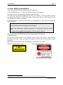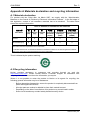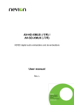
1
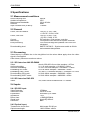
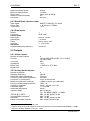
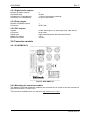
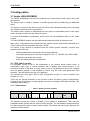
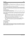
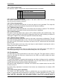
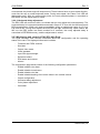
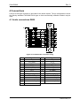
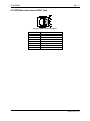
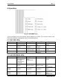
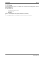
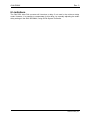
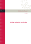
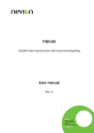
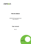
AVA-DMUX Fiber to analog video and audio module User manual Rev. 3 Nevion Europe P.O. Box 1020, 3204 Sandefjord, Norway – Tel: +47 33 48 99 99 – Fax: +47 33 48 99 98 www.nevion.com AVA-DMUX Rev. 3 Nevion Support Nevion Europe Nevion USA P.O. Box 1020 3204 Sandefjord, Norway Support phone 1: +47 33 48 99 97 Support phone 2: +47 90 60 99 99 1600 Emerson Avenue Oxnard, CA 93033, USA Toll free North America: (866) 515-0811 Outside North America: +1 (805) 247-8560 E-mail: [email protected] See http://www.nevion.com/support/ for service hours for customer support globally. Revision history Current revision of this document is the uppermost in the table below. Rev. Repl. Date Sign 3 2 2011-01-25 AA 2 1 2009-03-20 NBS 1 0 0 - 2007-10-15 2006-03-09 AS MDH Change description New template. Minor change to Chapter 2.2. Updated Declaration of Conformity. Total update, following from replacing discontinued AAV-DMUX with new AAV-SD-DMUX New front page. First release of product. nevion.com | 2 AVA-DMUX Rev. 3 Contents Revision history .......................................................................................................... 2 1 Product overview ..................................................................................................... 4 1.1 AVA-DMUX-C2 ................................................................................................................ 4 1.2 AAV-SD-DMUX(-R) ......................................................................................................... 4 1.3 DAC-SDI ......................................................................................................................... 4 1.4 Signal flow ....................................................................................................................... 5 2 Specifications .......................................................................................................... 6 2.1 Measurement conditions.................................................................................................. 6 2.2 General ........................................................................................................................... 6 2.3 Processing....................................................................................................................... 6 2.4 Inputs .............................................................................................................................. 6 2.5 Outputs............................................................................................................................ 7 2.6 Connector module ........................................................................................................... 8 3 Configuration ........................................................................................................... 9 3.1 Audio (AAV-SD-DMUX) ................................................................................................... 9 3.2 Video (DAC-SDI) ............................................................................................................14 4 Connections........................................................................................................... 17 4.1 Audio connections DB25 ................................................................................................17 4.2 GPI/Data connections 8P8C Jack...................................................................................18 5 Operation ............................................................................................................... 19 5.1 DAC-SDI LEDs ...............................................................................................................19 5.2 AAV-SD-DMUX LEDs .....................................................................................................19 5.3 GPI alarms .....................................................................................................................20 6 Limitations ............................................................................................................. 21 7 Laser safety precautions........................................................................................ 22 Appendix A Materials declaration and recycling information..................................... 25 nevion.com | 3 AVA-DMUX Rev. 3 1 Product overview The AVA-DMUX unit actually consists of three modules: The AVA-DMUX-C2 connector backplane. The AAV-SD-DMUX(-R) AES and Analog Audio De-embedder (with optical receiver). The DAC-SDI universal SDI to Analog Video converter. 1.1 AVA-DMUX-C2 The AVA-DMUX backplane has all the necessary connections for the audio and video signals. It also has all of the inter-connections between the two processing cards. There is no SDI output. 1.2 AAV-SD-DMUX(-R) The AAV-SD-DMUX is a highly integrated audio embedding module in the Flashlink range, offering de-embedding of audio from a digital SD serial video signal. In the AVA-DMUX application, the AAV-SD-DMUX can: De-embed and embed all groups of audio. Copy or move audio groups without additional delay. De-embed 2 AES3 digital audio and non-audio signals. De-embed 4 analog audio signals. Apply extra audio delay. Swap stereo channels. Make mono or sum from stereo signals. Have optical input. Transport asynchronous serial data. Generate video and audio signals. De-glitch correctly synchronized switched video. The optical receiver is compatible with both single and multi-mode optical fiber and may be used as a receiver in point to point, CWDM and DWDM configurations. 1.3 DAC-SDI The Flashlink DAC-SDI is a high-quality 10-bit digital 4:2:2 to NTSC/PAL composite encoder and component (4 outputs, 54MHz oversampled) analog video converter. The card can produce both composite and component formats simultaneously on the outputs. The input frame buffer (9 fields) and adjustable horizontal delay can provide a programmable delay relative to the input signal or, when present, the reference black-burst signal. A low latency mode is also available if the frame buffer is not to be used. The analog output video is synchronous to the input signal if no black-burst signal is present. If a stable black-burst reference signal is present, the output video will be synchronous to the reference. If the input SDI signal has a field one identifier signal embedded in line 7, the DAC-SDI will synchronize to the correct 8 field pal or 4 field NTSC frame sequence. DAC-SDI may be configured via switches on the unit, or via the GYDA control interface. nevion.com | 4 AVA-DMUX Rev. 3 1.4 Signal flow Figure 1: AVA-DMUX signal flow The digital video comes either through the SDI receiver or the optical receiver. EDH information is processed in the de-serializer and the signal passes to the de-embedding processor. The video signal is then re-serialized and sent to the frame synchronizer. The output of the frame synchronizer is sent to the video d/a converter chip where it is decoded into the required format. The outputs are filtered and the dc levels are corrected. The digital audio comes from the de-embedding processor and goes to the d/a converters. The gain is adjusted before the audio is fed to each of the outputs. The de-embedder module has two main processing blocks. One processes the video stream and the packet data, the other processes the audio. The packet processing core forms a group router which can route embedded audio between groups without any extra delay. The AAV-SD-DMUX audio core is an AES3 stereo audio router. The received embedded audios are the sources in the router. The embedded output groups and audio outputs are the destinations. This feature may also be used to perform stereo channel swapping. Four stereo delay lines are also available in the router with a total combined delay of 1.25s. Audio processing is possible within each stereo output. The channels may be changed allowing L/R swapping, mono assignment, summing, MS conversion and phase reversal of one of the signals. All embedding and de-embedding is performed with synchronous 48 kHz audio nevion.com | 5 AVA-DMUX Rev. 3 2 Specifications 2.1 Measurement conditions Audio Sampling rate: Ambient temperature: Measurement bandwidth: Detector: Input overload level (0 dBFS): 48 kHz. 25ºC. 20 Hz-20 kHz. RMS. +18 dBu. 2.2 General Power, AAV-SD-DMUX: +5V DC / 0.72A, 3.6W +/-15V DC / 0.02A, 0.6W. +5V DC / 0.62A, 3.1W, -15V DC / 0.46A, 0.7W. DIP switches, Gyda system controller. Front panel LED’s and GYDA system controller. Full. Received flags are updated; new CRCs are calculated. SMPTE S272M C – Synchronous audio at 48 kHz and extended data packets. Power, DAC-SDI: Control: Monitoring: EDH processing: De-embedding level: 2.3 Processing Video latency is variable due to the de-glitcher but the values below apply when the video signal is first applied. Other latency values are maximum values. 2.3.1 SD latencies AAV-SD-DMUX Video: Audio embedding: Audio de-embedding: Embedding GPI mode: Embedding UART mode: De-embedding GPI mode: De-embedding UART mode: des+4+350+256+2+ser video samples = 45.3us 2+1+16 audio samples = 19/48000 = 396us 4+16+1+29 audio samples = 50/48000 = 1.04ms 8+4+32 96kHz samples = 44/96000 = 458us 32+128+17+16 96kHz samples = 193/96000 = 2.01ms 8+32+8 96kHz samples = 44/96000 = 458us 8+32+8 96kHz samples = 48/96000 = 458us 2.3.2 SD latencies DAC-SDI Video: 3us; when locked to Black Burst: 1-2 frames. 2.4 Inputs 2.4.1 SD-SDI input: Video Data rate: Video frame rate: Equalization: Impedance: Return loss: Signal level: Connector: 270Mbps. 50 Hz or 60 Hz. Automatic up to 35dB. 75 Ω. >15dB @270MHz. Nominally 800mV. BNC. 2.4.2 Optical input: Transmission circuit fiber: Optical wavelength: Multi-mode 50/120 µm. 1200-1550nm ±40nm. nevion.com | 6 AVA-DMUX Rev. 3 Maximum Optical power: Minimum Optical power: Return loss: Maximum reflected power: Connector: 0 dBm. -26 dBm. better than 40 dB typ. 4%. SC/UPC. 2.4.3 Black Burst reference input Input signal: Return loss: Termination: SMPTE 170M/ PAL ITU 624-4 > 35 dB up to 5.75MHz 75 Ω 2.4.4 Data inputs RS422: Connector: Packet mode: Baud rates: Data length: Parity: Stop bits: GPI mode: Raw data sampling frequency: 1 8P8C Jack 9600 to 115200 7 or 8 bits None, odd or even 1, 1.5 or 2 bits 93750 Hz 2.5 Outputs 2.5.1 Video outputs Number of video outputs: Formats: Connector: Impedance: Return loss: Signal level: 4 YUV+CVBS, RGB+CVBS, YC+Y+CVBS, YC+BB+CVBS BNC 75 Ω > 35dB up to 5.75 MHz 1V. 2.5.2 Analog Audio outputs: Number of outputs: Sampling frequency: Differential output impedance: Common mode output impedance: Connector (C1 backplane): Maximum signal level (0 dBFS): Common mode voltage tolerance: Frequency response: Pass-band ripple: Stop band attenuation: Dynamic range1: THD+N @ -1 dBFS: Intermodulation distortion3: Crosstalk: CMRR (1kHz BBC method): 4. 48 kHz. 53 ohms. 20 kohm. 25 pin D-sub female. +24dBu or lower in 0.5 dB steps. +50V, -0V 20 Hz – 20 kHz +/-0.1 dB +/- 0.002 dB 82 dB Min. 99 dB (A)2; Typ. 105 dB(A) 0 dBFS = +18dBu. Max. -85 dB, typical -96 dB. Max. -90 dB Max. -90 dB, typical -95 dB. Max. 46 dB, typical 65 dB. 1 |THD+N of -60 dBFS 1 kHz signal| + 60. Dynamic range scales with output full scale level. Minimum result is obtained with 0dBFS = +12dBu. 3 Signal at -12 dBFS, SMPTE 4:1 60 Hz + 7 kHz. 2 nevion.com | 7 AVA-DMUX Rev. 3 2.5.3 Digital Audio outputs Number of AES3 outputs: Audio data rate: Impedance (C1 backplanes): Connector (C1 backplanes): 4 48 kHz 110 ohm transformer balanced. 25 pin D-sub female. 2.5.4 Data outputs Number of RS485 outputs: Connector: 1 8P8C Jack 2.5.5 GPI outputs Signals: Connector: Signal type: Maximum voltage: Maximum current: Power status good, no video input lock, laser failure. 8P8C Jack Open drain transistor with free-wheel diode. 100 V 150 mA 2.6 Connector module 2.6.1 AVA-DMUX-C2 Figure 2: AVA-DMUX-C2 2.6.2 Mounting the connector module The details of how the connector modules are mounted can be found in the user manual for the sub-rack frame: FR-2RU-10-2. This manual is available from our web site: http://www.nevion.com/ nevion.com | 8 AVA-DMUX Rev. 3 3 Configuration 3.1 Audio (AAV-SD-DMUX) The DMUX embedding core can be considered as a 14x16 stereo audio router and a 5x4 group router. The group router is used to transport or shuffle groups without introducing any additional delay. The inputs or sources in the stereo router are from the de-embedded audio groups, the delay line outputs and the two built in generators. The stereo router outputs or destinations are the groups of embedded audio in the output video, the audio outputs and the delay line inputs. A normal de-embedder configuration would route the de-embedded audio to the audio outputs. The AAV-SD-DMUX module can de-embed and re-embed/ shuffle at the same time! Many other configurations are possible and the module may be dynamically controlled as a 14x16 audio router via the system controller, GYDA. Full control of the module is performed with the GYDA system controller. Controls only possible with GYDA are: The data transmission parameters and channel selection. The output processing of each stereo signal (LR, RL, LL, RR, MS, Sum, ØLR, LØR). The delay lines delays and routing. Video and audio generator configuration. 3.1.1 DIP switch routing Full hardware control of all of the parameters in the module would require either, a complicated menu type of control interface with a display and control buttons; or an enormous number of switches. In many cases, most of the parameters will not be changed from the default settings. It was decided to control only the most used parameters with switches. This still requires the use of 24 switches. The switches are only read if SW1.8 (DIP configuration mode) is in the on position (see Chapter 3.1.2.2). There are not enough switches on the module to allow full stereo routing configurations. Groups of four channels are routed together as units, for example: AES input channels 1&2, embedded audio group 1. 3.1.1.1 Destinations Table 1: Routing control switches Group1 SW1 Group2 1 2 3 4 5 6 * * Group3 SW2 Group4 * * DAC 1&2 7 8 1 4 7 8 1 2 3 5 6 2 SW3 AES 3&4 3 4 5 6 * * 7 8 The switches control the routing of signals to the outputs or destinations. There are four embedded audio groups and two pairs of audio outputs. The configuration assigns sources to output groups and pairs of stereo audio outputs. This allows the same input signals to be routed to several outputs. nevion.com | 9 AVA-DMUX Rev. 3 There is a group of three switches for each of the outputs. The combination of the three switches set the input source or disables the output e.g. Group 1 embedded output is controlled by switches on SW1 positions 1, 2 and 3. The analog audio outputs are controlled by switches on SW3 positions 1, 2 and 3. 3.1.1.2 Sources There are eight possible permutations of the switches. Seven of the permutations choose the input sources. One of the settings (off, off, off) is used to disable the group embedding or set the AES outputs to silence. Table 2: Source switch encoding Switch Output group1 disabled 1 or 2 2 or 5 3 or 6 group2 group3 on on on group4 on on DAC 1&2 on on AES 3&4 on on Stereo tone on on on 3.1.1.3 Examples Figure 3: Example 1 The module above (Figure 3) is set to the following: Group1 output is embedded with signals from AES1&2 inputs Group2 output is embedded with signals from AES3&4 inputs Group3 output is embedded with signals from de-embedded group3 Group4 output is not embedded Analog DAC outputs signals from de-embedded group1 AES 3&4 outputs signals from de-embedded group2 nevion.com | 10 AVA-DMUX Rev. 3 Figure 4: Example 2 The module above (Figure 4) is set to the following: Group1 output is embedded with signals from de-embedded group1 Group2 output is embedded with signals from AES1&2 inputs Group3 output is embedded with signals from AES3&4 inputs Group4 output is not embedded Analog DAC outputs signals from de-embedded group1 AES 3&4 outputs signals from de-embedded group1 Users familiar with binary numbers may see that source numbers 1 to 4 (001 to 100) correspond to groups 1 to 4. Binary numbers 5 (101) and 6 (110) are not used on this module. 3.1.2 Other DIP Switches 3.1.2.1 Audio DAC converter gain, SW1.7, SW2.7 and SW3.7 The DAC convert output levels may be set to one of the eight preset levels with the DIP switches. The analog levels correspond to the maximum sine wave level, otherwise known as 0 dBFS. The three switches are labeled S2, S1 and S0 on the board. The combinations of the three switches set up the output level as shown in the table. 0 is off or down, 1 is on or up. S2,S1,S0 000 001 010 011 100 101 110 111 Level +12 +13.5 +15 +16.5 +18 +20 +21 +24 (dBu) All four input levels are set by the DIP switches in DIP configuration mode. GYDA can set the levels for each channel individually. 3.1.2.2 DIP Configuration, SW1.8 SW1.8 on, forces the DIP switch configuration to be used. If there is a GYDA present, the switch configuration on the module will be used and the configuration will be just be monitored in the GYDA controller. SW1.8 off will not use the DIP switches but will be configured from either the stored configuration in the module or from GYDA if there is GYDA present. The configuration will be nevion.com | 11 AVA-DMUX Rev. 3 stored when a GYDA configuration command is used. Therefore if a GYDA is present, the internal configuration will be overwritten by the GYDA controller. The switch settings are only read when the module is powered up. The DIP switch settings control the routing and a couple of other important settings. Other stored settings, such as data embedding and generator settings will always be used. 3.1.2.3 EDH insert, SW2.8 SD video output from the module will only contain an EDH packet if SW2.8 is on. 3.1.2.4 AES Output 1&2 SW3.8 AES outputs 1&2 are extra outputs fed either from the same signals as the DAC converters or the AES outputs 3&4. AES outputs 1&2 are fed with the same signals as the DAC converters if the switch is in the off position. 3.1.3 GYDA Control Full control of the stereo audio router is possible with the GYDA system controller. The module stores its routing configuration in non-volatile memory when a GYDA command is given. This allows complex configurations to be restored after a power loss. If a GYDA system controller is present, the last configuration of the module will be only be restored by GYDA if SW1.8 is off. The intention is that SW1.8 is used to show that the card is manually configured when switched on. 3.1.3.1 Audio delay lines The unit has four stereo audio delay lines connected to the audio router. Audio to be delayed is routed to one of the delay inputs and the output of that delay is routed to the intended output. The length of each delay line is set up on the configuration page of GYDA. The maximum delay for each of the four delays is 16384 audio samples, which is about 341ms. The delay lines may be cascaded if longer delays are required. 3.1.3.2 Stereo audio processing The output of each stereo signal may be manipulated (LL, RR, LR, RL ØLR, LØR, (L+R)/2, MS) this is controlled with the GYDA controller. The stereo signals may be output in one of the following ways: - LR - RL - LL - RR - ØLR - LØR - (L+R)/2 - MS Left / Right Right/ Left Left/ Left Right/ Right ØLeft/ Right Left/ ØRight Left + Right MS/AB No change. Channels are swapped. Left channel is copied into the right channel. Right channel is copied into the left channel. The left channel is phase inverted. The right channel is phase inverted. The left and right channels are summed. The left and right channels are converted from AB stereo to MS stereo. The sum products ((L+R)/2 and MS) are reduced in level by 6 dB to avoid any possibility of clipping. 3.1.3.3 RS422 Data port configuration The RS422 data 8P8C Jack input must be configured with GYDA. The baud rate, data length, parity and stop bits must be configured if UART mode is used. The router destination where the data is to be embedded must be set up and the source channel containing the received data that will be output on the 8P8C Jack must be also be configured. See also Chapter 3.1.4 below. nevion.com | 12 AVA-DMUX Rev. 3 3.1.3.4 Transport and shuffling of audio groups The AAV-SD-DMUX stereo audio router involves de-embedding, buffering and re-embedding which introduces a small delay relative to the video signal. The group router is used to avoid this extra delay. Groups that only pass through the group router are re-embedded in the same video line. This avoids any extra delay and means that incompatible audio formats (asynchronous audio) may still be transported. The AAV-SDDMUX automatically uses the group router whenever possible when controlled with the DIP switches. “Shuffling” of groups is when existing embedded audio groups are re-assigned to different groups. Copying of groups is also possible i.e. Group 1 may be transported to Group 1 and duplicated to Group 2. This function also takes place in the group router which means that there is no extra delay. 3.1.3.5 Audio generator The stereo audio generator is available in the audio router as a source. It is a high purity 1 kHz sine wave with a 250ms interruption on the left channel every 3 seconds. The audio level may be set to one of two standards. The two levels are -18 dBFS and -20 dBFS. These two levels correspond to EBU R68 and SMPTE RP 155. 3.1.3.6 Video generator The video generator has several different simple signals: Color bar, 100% white, 75% colors, no set-up level. Red, Green, Blue or Black full field. The generator may be used as the video source if there is no video signal present at either of the video inputs. The generator may also be switched on with GYDA. This will override video input but the generator signal will be locked to the input. The video standard of the generator may be set with GYDA but only if there is no video input present. 3.1.4 Data transmission The module can de-embed and embed asynchronous data. An AES3 audio signal is used as a carrier. Both embedded audio and normal AES3 signals may be used to carry the RS422 data. The fiber connection usually only goes one direction so any desired return path must be created by the user with another circuit. Return data may be sent over fiber via a link comprising of AAV-SD-DMUX, D422 or D422-MG modules. The 8P8C Jack data input works in one of two modes: UART Mode: The data is checked for correct reception according to the configuration. The data words are packaged and sent when present. Raw sampling mode: The data input is sampled at 93.75 kHz and embedded as a data stream. No checking is performed. 3.1.4.1 Data latencies The data channel has a total latency of approximately 30us when using raw sampling. Normal data rates of up to 9600 may be used with raw data sampling to have a low latency. The latency is 500us when using the normal data encoding due to the block structure of the AES User bits. The configuration of the data channel is always stored in the module and used regardless of the GYDA override switch. nevion.com | 13 AVA-DMUX Rev. 3 3.1.4.2 Embedding The AAV-SD-DMUX has a RS422 data input for the embedding of control data. The baud rate and other parameters are configured with GYDA. The factory default is 115200 baud, no parity, one stop bit. The data channel is encoded in the User bits in an embedded audio stereo signal assigned with GYDA. The factory default is Audio channels 1&2 in Group 1. The data is sampled asynchronously at a constant bit rate. The range of baud rates is from DC to 115,200 bps. The data bytes are either encoded as packets in the transmitted data or transmitted as an asynchronous bit stream which may also be used to transmit a DC signal such as GPI. 3.1.4.3 De-embedding The audio channel with the data signal to be de-embedded must be configured by GYDA as there may be several data channels available. The AAV-SD-DMUX will automatically detect the data channel format when present and output the data on the 8P8C Jack connector. The output driver will only be active when data is output in UART mode. The means that the output is always active when raw data is used. 3.1.4.4 Limitations 1. There is one thing the user must do in order to receive embedded data. The audio source where the data is embedded must be routed to a destination in the stereo router. This is because the extraction of the data takes place on the output of the router. Example: Data is to be de-embedded from embedded audio channels 1&2. Embedded audio channels 1&2 routed to output to Delay 4. 2. The normal UART mode checks the data when receiving and only embeds valid bytes. The data format must be correct. This also means that a BREAK condition of many spaces will not be detected or transmitted. Contact support if this is a requirement. 3.2 Video (DAC-SDI) 3.2.1 DIP switches 3.2.1.1 Manual mode DIP switch 1 should be in the ON position if the card is to be controlled with the other DIP switches. If the switch is OFF then the card starts with the stored configuration and the other switches are ignored. GYDA is always able to re-configure the card but the new configuration will only be remembered if switch 1 is OFF. nevion.com | 14 AVA-DMUX Rev. 3 3.2.1.2 Video output mode DIP switches 2 and 3 configure the output modes as shown in the table. Switch 3 2 0 0 0 1 1 0 1 1 Output Video Mode RGB component and Composite YUV component and Composite Composite, Y, C and Y Composite, Y, C and Black-Burst 3.2.1.3 Vertical interval blanking DIP switch 4 should be in the ON position if the active video lines in the video blanking interval should be erased or blanked. 3.2.1.4 Color bar generation DIP switch 5 should be switched ON if a color bar signal is to be generated. The output will be frequency locked to the reference if present but the phase is arbitrary. 3.2.1.5 Minimum delay mode DIP switch 6 should be switched ON if conversion with low delay is required. The reference input is not used in this mode and the frame synchronizer is bypassed. 3.2.1.6 Video standard DIP switch 7 sets the default video system. OFF is 525/60 (NTSC). ON is 625/50 (PAL). This switch is used to determine the internal configuration while the card is booting, and before a valid signal is applied. Any valid input signal will override this setting. 3.2.1.7 Restore factory settings DIP switch 8 should be used if the card is to be reset to the factory configuration. This will also reset the delay parameters to zero. The card is reset when the card is powered up with this switch set ON. DIP switch 8 should be set back to the OFF position and the card should then be reset. Note: The reset button at the top of the card may be used instead of removing the card or switching the power supplies on and off. 3.2.1.8 Reserved switches DIP switch 9 is reserved for future use and should be in the OFF position. DIP switch 10 chooses programming or run mode and should always be in the ON position. 3.2.2 Pushbuttons The DAC-SDI has three push-buttons at the front of the card. The upper button is used to reset the card while the other two, located next to the LEDs, are used to adjust the output timing parameters. 3.2.2.1 Adjustment mode To avoid the possibility of unauthorized tampering, the button interface must be enabled by holding both the INC and DEC buttons depressed. The two lower LEDs on the front of the card will blink alternately while the buttons are depressed. Sub-carrier phase adjustment is selected if the buttons are released when the third LED (Frame Lock) is lit. Horizontal delay adjustment is selected if the buttons are released when the bottom LED (EDH) is lit. 3.2.2.2 Sub-carrier phase adjustment The Frame Lock LED continues to blink, to indicate that you may adjust the phase. The phase is incremented and decremented in 256 steps. A phase adjustment from 0° through 360° is available. The single step size is approximately 1.41° around 0. The adjustment is made with the INCrement and DECrement buttons. When the maximum range is nevion.com | 15 AVA-DMUX Rev. 3 encountered, the phase angle will wrap-around. These buttons have an auto-repeat function, much like the way a normal keyboard works. During auto-repeat, the Frame Lock LED will light continuously. After a 6 second idle period, the newly adjusted phase is committed to EEPROM, and the adjust-state is exited. 3.2.2.3 Horizontal delay adjustment The EDH LED will continue to blink, to indicate that you may adjust the horizontal delay. The horizontal delay is incremented and decremented in steps of 37.0 ns with the INCrement and DECrement buttons. 2048 such steps are available, giving an adjustment range of ±37.9 µs PAL and NTSC. During auto-repeat, the EDH LED will light continuously. When neither the INC nor the DEC button has been touched for 6 seconds, the newly adjusted delay is committed to EEPROM memory, and the adjust-state is exited. 3.2.3 Monitoring and control of DAC-SDI with Gyda The Gyda controller card receives information about the configuration and the operating status of the card. The displayed information includes: Firmware and FGPA versions Slot label Output video mode Video standard Input SDI signal strength Reference status EDH status and counter Alarms The configuration page allows control of the following configuration parameters Enable/ disable color burst. Enable/ disable chrominance. Enable/ disable color bar. Enable/ disable blanking of the active video in the vertical interval. Output configuration. Horizontal delay adjustment. Color phase adjustment. Card label. nevion.com | 16 AVA-DMUX Rev. 3 4 Connections A 25 pin d-sub type connector is provided for the audio outputs. The pin configuration used is the industry standard TASCAM DA-88 type so that commercially available 'snakes' may be used. 4.1 Audio connections DB25 Figure 5: D-sub 25 audio connector wiring Pin 1 2 3 4 5 6 7 8 9 10 11 12 13 Signal 2R (+) 2R (GND) 2L (-) 1R (+) 1R (GND) 1L (-) AES 4 OUT (+) AES 4 OUT (GND) AES 3 OUT (-) AES 2 OUT (+) AES 2 OUT (GND) AES 1 OUT (-) Pin 14 15 16 17 18 19 20 21 22 23 24 25 Signal 2R (-) 2L (+) 2L (GND) 1R (-) 1L (+) 1L (GND) AES 4 OUT (-) AES 3 OUT (+) AES 3 OUT (GND) AES 2 OUT (-) AES 1 OUT (+) AES 1 OUT (GND) GND nevion.com | 17 AVA-DMUX Rev. 3 4.2 GPI/Data connections 8P8C Jack Figure 6: 8P8C connector layout Pin number 1 2 3 4 5 6 7 8 Description Power present No Video signal Laser failure RS485/422 output + RS485/422 output RS422 input + RS422 input Ground nevion.com | 18 AVA-DMUX Rev. 3 5 Operation Figure 7: AVA-DMUX LEDs (Text not printed on the front panel). Each module has 4 LEDs. The colors of each of the LEDs have different meanings as shown in the tables below. 5.1 DAC-SDI LEDs Diode \ state Power Frame lock Red LED Major error. Remove module Video signal absent. No reference BB EDH status Errors detected SDI Input Orange LED n/a Weak signal present BB present but unable to lock n/a Green LED Module power is OK Good signal present BB reference present No errors detected No light Module has no power Minimum delay mode 5.2 AAV-SD-DMUX LEDs Diode \ state Card status Red LED PTC fuse has been triggered or FPGA programming has failed Video signal absent. Orange LED Module has not been programmed Green LED Module is OK No light Module has no power Electrical video signal present Optical video signal Present Group 1&2 status: Group 1 & 2 not present Either group 1 or Both group 1 & 2 present 2 present Group 3&4 status: Group 3 & 4 not present Either group 3 or Both group 3 & 4 present 4 present Module has not been programmed Module has not been programmed Module has not been programmed Input status nevion.com | 19 AVA-DMUX Rev. 3 5.3 GPI alarms Only three alarms are present on the 8P8C Jack connector as four of the pins are used for the RS422 data port. The three alarms are: Power present (negative logic) Video signal lost Laser failure An active alarm condition means that the transistor is conducting. The power present alarm should always be active during normal operation. nevion.com | 20 AVA-DMUX Rev. 3 6 Limitations The DAC-SDI video D/A converter will introduce a delay if not used in the minimum delay mode. However, it is possible to compensate for this delay, by manually adjusting the audio delay settings in the AAV-SD-DMUX, using GYDA System Controller. nevion.com | 21 AVA-DMUX Rev. 3 7 Laser safety precautions These are guidelines to limit hazards from laser exposure. All the available EO and –T units in the Flashlink range include a laser. Therefore this note on laser safety should be read thoroughly. The lasers emit light at wavelengths from 1270nm up to 1610nm. This means that the human eye cannot see the beam, and the blink reflex cannot protect the eye. (The human eye can see light between 400 nm to 700 nm). A laser beam can be harmful to the human eye (depending on laser power and exposure time). Therefore: Be careful when connecting / disconnecting fiber pigtails (ends). Never look directly into the pigtail of the laser/fiber. Never use microscopes, magnifying glasses or eye loupes to look into a fiber end. Use laser safety goggles blocking light at 1310 nm and at 1550 nm Instruments exist to verify light output power: Power meters, IR-cards etc. Flashlink features: All the laser module cards in the Flashlink product range, are Class 1 laser products according to IEC 825-1 1993, and class I according to 21 CFR 1040.10 when used in normal operation. More details can be found in the user manual for the FR-2RU-10-2 frame. Maximum output power4: 5 mW 4 Operating wavelengths: > 1270 nm Max power is for safety analysis only and does not represent device performance. nevion.com | 22 AVA-DMUX Rev. 3 General environmental requirements for Nevion equipment 1. 2. - The equipment will meet the guaranteed performance specification under the following environmental conditions: Operating room temperature range: 0°C to 45°C Operating relative humidity range: <90% (non-condensing) The equipment will operate without damage under the following environmental conditions: Temperature range: -10°C to 55°C Relative humidity range: <95% (non-condensing) nevion.com | 23 AVA-DMUX Rev. 3 Product Warranty The warranty terms and conditions for the product(s) covered by this manual follow the General Sales Conditions by Nevion AS. These conditions are available on the company web site of Nevion AS: www.nevion.com nevion.com | 24 AVA-DMUX Rev. 3 Appendix A Materials declaration and recycling information A.1 Materials declaration For product sold into China after 1st March 2007, we comply with the “Administrative Measure on the Control of Pollution by Electronic Information Products”. In the first stage of this legislation, content of six hazardous materials has to be declared. The table below shows the required information. Toxic or hazardous substances and elements 組成名稱 Part Name 鉛 汞 镉 六价铬 多溴联苯 多溴二苯醚 Lead Mercury Cadmium Hexavalent Polybrominated Polybrominated (Pb) (Hg) (Cd) Chromium biphenyls diphenyl ethers (Cr(VI)) (PBB) (PBDE) DAC-SDI O O O O O O AAV-SD-DMUX(-R) O O O O O O O: Indicates that this toxic or hazardous substance contained in all of the homogeneous materials for this part is below the limit requirement in SJ/T11363-2006. X: Indicates that this toxic or hazardous substance contained in at least one of the homogeneous materials used for this part is above the limit requirement in SJ/T11363-2006. This is indicated by the product marking: A.2 Recycling information Nevion provides assistance to customers and recyclers through our web site http://www.nevion.com. Please contact Nevion’ Customer Support for assistance with recycling if this site does not show the information you require. Where it is not possible to return the product to Nevion or its agents for recycling, the following general information may be of assistance: Before attempting disassembly, ensure the product is completely disconnected from power and signal connections. All major parts are marked or labeled to show their material content. Depending on the date of manufacture, this product may contain lead in solder. Some circuit boards may contain battery-backed memory device nevion.com | 25 EC Declaration of Conformity MANUFACTURER Nevion AS P.B. 1020, N-3204 SANDEFJORD, Norway AUTHORISED REPRESENTATIVE (Established within the EEA) Not applicable MODEL NUMBER(S) DAC-SDI AAV-HD-DMUX(-R)/ AAV-SD-DMUX(-R) DESCRIPTION SDI to NTSC/PAL Encoder/Component Analog Video Converter with Genlock HD/SD analog / digital audio de-embedder DIRECTIVES this equipment complies with Low voltage (EU Directive 2006/95/EC) EMC (EU Directive 2004/108/EC) RoHS (EU Directive 2002/95/EC) 5 China RoHS WEEE (EU Directive 2002/96/EC) REACH HARMONISED STANDARDS applied in order to verify compliance with Directive(s) EN 55103-1:1996 EN 55103-2:1996 TEST REPORTS ISSUED BY Notified/Competent Body Report no: Nemko E06114.01 E11038.00 TECHNICAL CONSTRUCTION FILE NO Not applicable YEAR WHICH THE CE-MARK WAS AFFIXED 2006 2008 TEST AUTHORIZED SIGNATORY MANUFACTURER AUTHORISED REPRESENTATIVE (Established within EEA) Date of Issue 2011-03-08 Place of Issue Not applicable Name Thomas Øhrbom Position QA Director, Nevion Europe (authorized signature) 5 Sandefjord, Norway Administration on the Control of Pollution Caused by Electronic Information Products Nevion Europe P.O. Box 1020, 3204 Sandefjord, Norway – Tel: +47 33 48 99 99 – Fax: +47 33 48 99 98 www.nevion.com