1
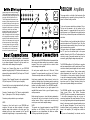
Lost keys can be replaced. Information is kept on file at the
factory about every REDGUM amplifier manufactured. By
quoting the Serial Number (on the under side of your
amplifier, on the carton, or on the Final Test Report),
another key can be provided.
Just Fax a request for a new key and your FINAL TEST
REPORT (noting any change of address) to:
REDGUM Australia - Fax +61 3 9897 1399.
A replacement key will be sent by Air Mail the same day.
*****
When turning the power ‘on’, a slight ‘pop’ may be heard
from the speakers. This is normal and will not damage your
loudspeakers. When turning the power ‘off’, the amplifier
will continue to operate until the reservoir capacitors are
exhausted; during this time odd sounds may be heard they also are normal and will not harm your speakers.
*****
DO NOT REMOVE THE COVER on your REDGUM amplifier;
there is the RISK of a FATAL ELECTRIC SHOCK.
*****
The only fuse used is the mains fuse located on the outside
of the case in a small compartment of the IEC mains input
connector. This connector is found where the mains power
cord plugs in at the rear of the amplifier. To check for a
‘blown’ fuse, turn off the power at the wall socket and
remove the plug. Pull the power cord from the IEC socket
and locate the small drawer under the socket. Remove the
drawer by pulling straight out. Pull the fuse from the holder
and check the fine internal wire. If it is incomplete, replace
it with the spare fuse located in the body of the drawer.
The fuse is a SAFETY device. DO NOT experiment with other
sized fuses. Severe damage and/or a FATAL electric shock
could result. REDGUM fuse values are as follows:
175watt amplifier used on 220-250v - 2Amp
175watt amplifier used on 100-120v - 4Amp
300Watt Amp. used on 220-250V - 4amp
300Watt Amp. used on 100-120V - 8amp
If in any doubt whatsoever - consult your dealer.
*****
Before returning your amplifier for repair service you
should try the following test. Disconnect all connectors
from inputs, Tape Out and speaker terminals. Connect a
pair of speakers (with attached leads) from another system
that you know is working. Also connect a CD player (using
its leads) that you know is working. By doing this, you can
establish whether the fault lies with the amplifier or
another part of your system.
Complete for Warranty Registration :
Name __________________________________________
Address ________________________________________
REDGUM
City ____________________________ Zip code________
Country ______________ Date of purchase__________
Place of purchase _______________________________
Model No._______________________________________
Serial No. (if any) ________________________________
Fax this page to the REDGUM Audio factory at
+613 9897 1399
or Email details (incl. S.N.) to
<[email protected]>
Operating Instructions &
Specifications
REDGUM Amplifier
Models
RGM175 & RGM300
Tape
CD
Out
Unpack the three units & check for damage.
The Left and Right power amplifiers are identical other than a fine coloured ring around the
input plugs, Red for Right, Black for Left.
The front panels have been matched to be
stacked so:- Right channel bottom: left channel middle; Preamp top. Place the right channel in the position for the bottom of the stack.
Next place the left channel on top, followed by
the Pre-amp. Use the 3pin control leads
packed with the pre amp to hook the Control
supplies from the preamp to both power
amps. This supply is used for the cooling fans
and to close the power-up relays. Locate the
supplied RCA audio leads and connect from
the Left Out of the preamp to the Input on the
left channel power amp. Likewise the Right
Out on the preamp to the Input on the Right
power amplifier. Use 3 x IEC power leads, 1
for the preamp and 1 for each power amp,
and connect to a power source or power
VCR
DVD
AmFm
Tu
Tape
1
AV1
Tape
2
AV2
REDGUM Amplifiers
Control
L
Left Out
FUSE
R
Right out
Input
Control
Speaker
FUSE
(red)
(black)
Input
Make sure that your REDGUM Amplifier is disconnected
from the mains power before making any input connections
to your other equipment. Failure to do so may result in an
electric shock and/or damage to the amplifier.
Connect your Compact Disc player to your REDGUM
amplifier using high quality RCA interconnects between your
player and the sockets labelled CD (Left output on CD to Left
input on Amplifier).
Connect a Video Cassette Recorder to the sockets labelled
VCR.(Left output on VCR to Left input on Amplifier).
Connect AmFm tuner to sockets labelled AmFm (Left output
on tuner to Left input on Amplifier).
Connect a Cassette deck or DAT tape to sockets labelled
Tape 1. (Left output on CD to Left input on Amplifier).
Connect any audio product to any unused inputs.
NOTE:
Connect any ‘Line Level’ inputs to your REDGUM input
sockets as all inputs are direct connected to the power
amplifier stages when selected on the front panel. Any
selected input is also direct connected to the Tape Out
sockets for ‘straight through’ or ‘unprocessed’ recording.
Control
Speaker
FUSE
(red)
(black)
Make sure that your REDGUM Amplifier is disconnected from
the mains power before making any connection to speaker
terminals. Failure to do so may result in an electric shock
and/or damage to the amplifier.
On each power amplifier there are 2 Red and 2 Black
terminals. For normal operation you will use only 1 Red and
1 Black terminal (the others are for Bi-Wiring - see below)
Using heavy speaker cable (2mm minimum), hook up the
speaker on the right side of your listening area by connecting
the positive terminal of the right speaker to the positive (red)
terminal on the Right channel of your REDGUM amplifier .
Connect the other terminal on your right speaker to the
amplifier Black terminal. Hook up your left speaker using a
similar proceedure.
Before turning the power on, check that wiring terminations
look neat and that no loose strands of wire are touching
another terminal. Failure to make neat connections may
result in poor sound and/or amplifier damage.
NOTE:
The second set of speaker terminals on larger REDGUM
amplifiers are for Bi-Wiring. Consult your dealer (with
information on your loudspeakers) for details on whether
Bi-Wiring is possible with your system.
The power switch is on the left of the front panel of the
pre-amplifier and is operated by the key provided. The
power is off when the key is vertical.
To turn on the power, rotate the key clockwise 1/4 turn.
The key can be removed in the ‘on’ position, but for
safety reasons it is suggested that the key be left in
when the power is on. If preferred, the key switch can be
left in the ‘on’ position and the power controlled from the
wall outlet.
The Input Selector is on the right-hand side of the front
panel and rotates from CD through to Tape 2. All of the
inputs have the same sensitivity, so any ‘line level’ input
can be connected to any position.
The layout shown on the diagram is preferable because
the C.D. input has the shortest path to the power
amplifier, followed by the VCR, etc.The label above the
controls is made of removable material and it can be
removed by gently lifting the edge and peeling back.
The REDGUM amplifier is fully Dual-Mono in operation
and has a separate level control for each channel. These
controls are normally moved together but can be moved
separately to achieve balance. These volume controls
should approximate live 'concert hall' levels at the 12
O’clock position. In this position “clipping” of the signal
is rare and no damage to speakers or amplifier should
result. However, pushing to the 2 O’clock position and
beyond can result in “clipping” distortion, which is the
major cause of speaker damage, so use with care!
The REDGUM amplifier uses new generation Metal
Oxide- doped Silicon, Field Effect Transistors
(MOSFETs), which can operate into impedances below
1 ohm without damage as they are not prone to
secondary breakdown like normal transistors. But longterm, very high listening levels with speaker impedances
below 4 ohms may cause the internal heatsinks to rise
past 80 degrees Centigrade. This will result in the
protective thermal cut-out operating and shutting off
power to the amplifier. (The cooling fans continue to
run).
The power will automatically be restored once the