1
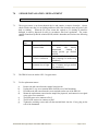
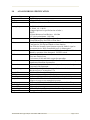
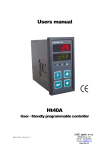
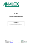
ANALOX SENSOR TECHNOLOGY LTD
ANALOX DD1101
INSTALLATION & OPERATION MANUAL
SAFETY WARNING
Please Refer to the Safety Warning in Section 7.1
regarding the chemicals in the oxygen sensor
Analox Sensor Technology Ltd.
15 Ellerbeck Court
Stokesley Business Estate
Stokesley
North Yorkshire
TS9 5PT
UK
Tel
+44 (0) 1642 711400
Fax
+44 (0) 1642 713900
www.analox.net
[email protected]
ANALOX DD1101 Oxygen Analyser User Manual DHO-812 Issue 2
Page 1 of 13
TABLE OF CONTENTS
1.0
2.0
3.0
4.0
5.0
6.0
7.0
8.0
9.0
INTRODUCTION ........................................................................................................................3
MEASURING RANGE................................................................................................................3
ANALOG OUTPUT.....................................................................................................................3
ALARM SYSTEM .......................................................................................................................4
INSTALLATION .........................................................................................................................5
OPERATION................................................................................................................................7
SENSOR INSTALLATION / REPLACEMENT.......................................................................11
RESPONSE TIME......................................................................................................................12
ANALOX DD1101 SPECIFICATION ......................................................................................13
ANALOX DD1101 Oxygen Analyser User Manual DHO-812 Issue 2
Page 2 of 13
1.0
INTRODUCTION
The ANALOX DD1101 Oxygen Analyser is intended to measure oxygen in the range 0-100% at
normal atmospheric pressure.
It may be configured at the time of order for
a)
b)
120V AC or 230VAC mains operation
0-5V or 4-20mA Analog output
It is possible to convert the unit in the field between any of these modes of operation. Consult Analox
for assistance.
2.0
MEASURING RANGE
The instrument will measure oxygen in the range 0.0 to 100.0%
Note that values may appear on the display in excess of the normal ranges. This depends on the
specific output of each particular sensor and the calibration points specified. The display will flash
‘Over’ if the measuring circuits reach their upper limit.
3.0
ANALOG OUTPUT
The instrument is factory configured for either a 4-20mA output or a 0-5V output representing 0-100%
oxygen.
ANALOX DD1101 Oxygen Analyser User Manual DHO-812 Issue 2
Page 3 of 13
4.0
ALARM SYSTEM
4.1.
The instrument provides a high oxygen alarm. This is annunciated via a RED LED on the
front panel of the instrument and an alarm relay, which provides Common (COM), Normally
Open (NO) and Normally Closed (NC) volt-free contacts. A facility is included to allow
connection of an external 5 Volt buzzer, via the screw terminals on the rear panel of the
Instrument.
4.2.
The relay is configured for fail safe operation. When the instrument is switched off, or is
subject to a power failure, the relay is de-energised, effectively indicating an alarm.
4.3.
When the instrument is switched on, the relay remains de-energised for a brief ‘warm up’
period. The relay operation is then dependant on the Oxygen level and the Alarm High
Setpoint. If the Oxygen reading is higher than the Alarm Setpoint, the alarm relay is deenergised, the LED starts to flash, and the audible buzzer, if fitted, is pulsed.
4.4.
The alarm is set as latching. Therefore, alarm states will only be cancelled by pressing the
front panel ENTER button.
4.5.
If the oxygen level remains above the setpoint, the audible buzzer can be silenced by pressing
the ENTER switch momentarily. The LED will continue to flash, and the relay will remain
de-energised until the oxygen level falls to a value, below 95% of the alarm setpoint. For
example, if the alarm setpoint is 40% the alarm function will trigger when the measured value
reaches 40.0% and will reset when the measured value reduces to 95% of 40% ie 38.0%.
4.6.
The alarm Setpoint can be altered by the operator, using the keys on the front panel.
ANALOX DD1101 Oxygen Analyser User Manual DHO-812 Issue 2
Page 4 of 13
5.0
INSTALLATION
5.1.
The Instrument is designed to be panel mounted in an aperture approximately 92 mm x 92
mm. The retaining clamps provided with the Instrument, can accommodate panel thickness up
to 30 mm. Remove the retaining clamps from the side panels of the Instrument and insert the
Instrument through the panel. Refit the side clamps and tighten the locking screws.
5.2.
Refer to the Label on the rear panel of the Instrument (See Drawing Below) and connect the
appropriate signal wiring to the 12 way two part screw terminal strip. (Sensor, Analog Output,
Horn, Inhibit, Relay)
Terminal Number
1
2
3
4
5
6
7
8
9
10
11
12
13
14
15
Signal Name
Sensor Screen
Sensor + (Red wire)
Sensor – (Black wire)
Analog Output +
Analog Output Horn +
Horn Inhibit
Inhibit
Relay NC
Relay COM
Relay NO
Earth
Mains AC Input (Neutral)
Mains AC Input (Live)
Comments
Not used with 9212-2 sensor
Oxygen Sensor Input connections
Analog Output
0-5V or 4-20mA
External Audible Alarm Connections
Inhibit Relay Connections
Alarm Relay Connections
Mains Input Terminals
5.3.
Ensure that the Oxygen Sensor connections are of correct polarity as shown in the table above.
5.4.
If the Analogue output signal is to be used, the necessary connections should be made at
Terminals 4 and 5 of the 12 way connector. Reference to the Customer Order and /or the
Calibration Certificate will indicate if the Instrument has been configured for a voltage (0 - 5
Volts) or Current (4 - 20 mA) Output.
5.5.
If the Alarm relay is to be used, then connections should be made to Terminals 10, 11 and 12
as appropriate. Note that under normal operating conditions ie no alarm present, the Relay
COM and Relay NO will form a closed circuit, since the Relay is normally energised. An
alarm condition will cause the relay contacts to change over, breaking the circuit between
COM and NO and closing COM and NC.
5.6.
If an external Audible warning device is to be used, then it should be connected to Horn + and
Horn- observing polarity. The Device should be capable of operating from 5 Volts DC and
should not draw current in excess of 50 milliamps.
ANALOX DD1101 Oxygen Analyser User Manual DHO-812 Issue 2
Page 5 of 13
5.7.
Connect the AC Power supply to the 3 way, two part screw terminal strip. Check that the
Power supply within the system (120v AC or 230v AC) agrees with the stated voltage on the
rear panel label of the Instrument and the Calibration Certificate.
5.8.
The Oxygen sensor should be mounted into the sample gas stream. Various flow adaptors are
available from Analox to assist the customer in mounting the sensor in a suitable position.
The sensor must not be subjected to any appreciable pressure. Typical flow rates of gas
through a flow adaptor will be between 0.1 and 1.0 litres per minute.
5.9.
It is very important that the gas delivery pressure and flow to the sensor, is kept constant, since
variations in pressure will result in erratic output signals and hence unstable readings on the
Instrument display. Vibrating diaphragm pumps should not be used to deliver the gas sample,
unless the pulsating output can be smoothed. It is also important that the gas sample outlet
from the cell’s flow adapter, is not restricted in any way - it must vent to atmospheric pressure.
5.10.
It is important that the gas sample being fed to the sensor is clean and of a non-corrosive
nature. If it is possible that contaminants or particulate may be present in the gas sample, then
the gas should be passed through filters and/or chemical absorbers, before being presented to
the sensor.
5.11.
Sample temperature should be in the range -5°C to +40°C and its Dew Point should always be
below Ambient temperature.
5.12.
Refer to Section 7 for details of Sensor Installation/Replacement
ANALOX DD1101 Oxygen Analyser User Manual DHO-812 Issue 2
Page 6 of 13
6.0
OPERATION
6.1.
FRONT PANEL KEYS
When the system is switched on, key functions, from LEFT to RIGHT, are as follows:
MENU
Press for 2 seconds to access Menu Functions (refer below)
UP
Press to display the current Alarm Setpoint.
DOWN
No action until Menu is selected.
ENTER
Press to Accept/Acknowledge alarms (silence buzzer, if fitted.)
6.2.
PASSWORD AND MENU SYSTEM
6.2.1
When the instrument is operating normally, press the MENU key for 2 seconds to access the
Menu facilities. These features are password protected. The password protection is always
implemented, when the instrument is first switched on.
6.3.
ENTERING PASSWORD
6.3.1
From normal measuring mode, press MENU for 2 seconds. The display will show the text
‘PASS’. The password is 1066.
6.3.2
Press ENTER. The display will show 1000.
6.3.3
Pressing UP or DOWN key will either increase or decrease the number on the display.
Maintain either switch pressed to change the value more rapidly. When the number is equal to
the pre-set password, press ENTER. If the password is entered correctly, the display will
change to display the first menu option ‘ALHi’. If the password is entered incorrectly, repeat
the procedure again.
6.3.4
When the correct password has been entered, the instrument will allow the user to access the
menu, for a further 30 minutes, without needing the password. This assumes that the
instrument is not switched off during the 30 minute period.
ANALOX DD1101 Oxygen Analyser User Manual DHO-812 Issue 2
Page 7 of 13
6.4.
MENU SYSTEM
6.4.1
The following options exist in the menu system.
a)
b)
c)
d)
ALHi
CALS
CAL0
inh
Alarm High Setpoint
Span Calibration
Zero Calibration
Inhibit Output
6.4.2
Having entered the menu system, press UP or DOWN to move forwards or backwards through
the menu options. Each option is then selected by pressing ENTER. Pressing MODE at any
time will revert back to normal measuring mode. If no keys are pressed for 60 seconds, the
instrument will also revert to normal measuring mode. Whilst in the menu system, the oxygen
alarm function is disabled.
6.4.3
Note there is also a fifth option (dFLt-Default Settings). This is only accessible if the ENTER
switch is held pressed while the instrument is switched on. (See 6.4.7 ‘Default Settings’
below)
6.5.
ALARM HIGH SETPOINT
6.5.1
Select ALHi in the menu and press the ENTER key. Press UP/DOWN until the display shows
the required alarm setpoint in the range 0.0-99.9. Press ENTER to select the new setting or
press MENU to revert to the previous setting.
6.6.
ZERO CALIBRATION
6.6.1
There will be a residual signal output from a Percent Oxygen sensor, when no Oxygen is
present at the gas input port. However, compared to the measuring range, the magnitude of
this signal is so small, as to be insignificant. Therefore, the Percent Oxygen sensors are not
characterised for an Offset value.
6.6.2
Zero point setting is normally only required when a replacement sensor is fitted to the
Instrument.
6.6.3
Access the MENU system and if necessary, enter the password as described in Section 6.2.
Select CAL0 and press the ENTER key. For a period of about 3 seconds, the display will
show a rapidly varying reading while the instrument carries out its internal electrical zero
adjustment.
6.6.4
At the end of this period, the display will revert to show CAL0 . Press the MENU key to
return to the normal operational mode.
ANALOX DD1101 Oxygen Analyser User Manual DHO-812 Issue 2
Page 8 of 13
6.7.
SPAN CALIBRATION
6.7.1
Before any calibration routines are carried out, consideration should be given to any peripheral
equipment which is connected or being controlled by the Instrument. A facility for disabling
an external PLC is incorporated in the Instrument. Refer to Section 6.8 for details.
6.7.2
Calibration of the Percent Instrument involves setting two reference points in the instrument’s
internal memory. These points are normally referred to as ‘SPAN’ and ‘ZERO’. Routine
calibration only requires adjustment of the ‘SPAN’ point. The ‘ZERO’ point will generally
only need to be calibrated, when a new sensor is fitted to the Instrument.
6.7.3
The calibration gas, used to set the SPAN point, may be normal atmospheric Oxygen or any
other source of Oxygen/Nitrogen mixture, whose Oxygen concentration is known. Calibration
gas should be in the range 20% to 100% as near as possible to the normal measurement range.
6.7.4
Ensure that the sensor has been subjected to the calibration gas, and that the reading on the
display has stabilised. The calibration procedure should NOT be carried out until the display
reading is steady.
6.7.5
Access the MENU system and if necessary, enter the password as described in Section 6.3.
Select CALS in the menu and press ENTER. The instrument’s internal digital reading, at the
time ENTER key is pressed, is stored temporarily and the display will freeze at the last
measured value.
6.7.6
The UP/DOWN keys should then be used to alter the display, until it shows the oxygen
concentration of the calibration gas, being used. If normal atmospheric air is being used, the
display should be set to 20.7 , allowing for effect of normal moisture content. If Instrument
Air from a cylinder is being used, the display should be set to 20.9 since this gas will normally
be much drier than atmospheric air.
6.7.7
When the value displayed is correct, press ENTER. Span calibration data will then be written
into the Instrument’s memory for use in all subsequent measurements. Exit the calibration
mode by pressing the MENU key. The Gas input connections to the Instrument sensor may
then be reconfigured to the normal measuring system.
6.7.8
Pressing MENU at any time during the above process, will cause the Instrument revert to the
previous settings. (Note the calibration data is not lost when the instrument is switched off.)
ANALOX DD1101 Oxygen Analyser User Manual DHO-812 Issue 2
Page 9 of 13
6.8.
INHIBIT OUTPUT
6.8.1
The inhibit output is intended to allow the instrument to indicate to an external device that its
output signal should not be interpreted ; for example, during a calibration procedure, or long
term purge down of a system. The inhibit relay contacts are presented externally, on the screw
terminals, on the rear panel of the Instrument. This function must be deliberately set by the
user.
6.8.2
Select the ‘inh’ option within the menu and press ENTER. Pressing UP/DOWN will toggle
the display from On to OFF. (OFF indicates the inhibit relay will not be energised and the
relay contacts will remain Open. On indicates the inhibit relay will be energised and the
contacts Closed). Pressing ENTER sets the relay in the desired state.
6.8.3
NOTE : When the Inhibit function is set to On, the front panel Red LED will be turned on, to
provide visual indication that the Inhibit output is enabled. All Alarm functions are disabled
when the Inhibit output is On.
6.9.
DEFAULT SETTINGS
6.9.1
This function allows an instrument which has been incorrectly calibrated and therefore
possibly inoperable, to be restored to a useable condition, without using calibration gas. The
Zero and Span calibration points will be based on theoretical conversion factors, which will be
correct for an Ideal Oxygen sensor. However, since there are variations in signal output
between sensors, this facility should only be considered a temporary solution and the
Instrument should be correctly calibrated as soon as possible.
6.9.2
To Select this option, the Instrument should be switched off and then switched on again whilst
holding the ENTER key pressed, until the RED Alarm LED has flashed 4 times. Release the
ENTER key.
6.9.3
Press the MENU key for 2 seconds and then the UP or DOWN key until the display shows
dFLt. Press ENTER, and the display will show OFF. Use UP or DOWN key to toggle OFF to
On. Pressing ENTER when the display shows ‘On’, will load default calibration constants.
ANALOX DD1101 Oxygen Analyser User Manual DHO-812 Issue 2
Page 10 of 13
7.0
SENSOR INSTALLATION / REPLACEMENT
SAFETY WARNING
7.1.
The oxygen sensor is an electrochemical device and contains a caustic electrolyte. Always
check to make sure that it is not leaking and do not allow the electrolyte onto any part of your
body or clothing.
When the life of the sensor has expired or it is leaking or otherwise
damaged it must be disposed of safely in accordance with local regulations. The sensor
contains Potassium Hydroxide solution (KOH) which is hazardous and can have the following
effects:
Body
Part
Skin
Effect
First Aid Procedures
Contact could result in Wash the affected part with a lot
a chemical burn.
of
water
and
remove
contaminated
clothing. If
stinging persists get medical
attention.
Ingestion Can be harmful or Drink a lot of fresh water. Do not
FATAL if swallowed.
induce vomiting Get medical help
immediately
Eye
Contact can result in the Wash with a lot of water for at
permanent loss of sight. least 15 minutes and get medical
help immediately
7.2.
The DD1101 uses an Analox 9212-2 oxygen sensor.
7.3.
To fit a replacement sensor:
a)
b)
c)
d)
e)
f)
g)
Remove the old sensor from the sample line pipework.
Unplug the 12 way screw terminal block from the rear of the Instrument.
Disconnect the old sensor from the screw terminals on the rear of the DD1101.
Mount the replacement sensor into the sample line pipework, and connect its two signal
wires to the screw terminals.
The RED sensor wire connects to Pin 2
The BLACK sensor wire connects to Pin 3.
Tighten the retaining screws and refit the terminal block into the 12 way plug on the
rear of the Instrument.
ANALOX DD1101 Oxygen Analyser User Manual DHO-812 Issue 2
Page 11 of 13
8.0
RESPONSE TIME
8.1 The T95 time of the Percent sensor (ie the time it takes from the onset of a step change in Oxygen
concentration at its gas input port, until the sensor output reaches 95% of its final value,
is
approximately 10 Seconds.
8.2 This time does not take into account the effect of extended pipework connected to the sensor gas
input port, in the monitoring system.
ANALOX DD1101 Oxygen Analyser User Manual DHO-812 Issue 2
Page 12 of 13
9.0
ANALOX DD1101 SPECIFICATION
Instrument Type
Range
Display
Resolution
Oxygen measurement
0 – 100.0%
4 Digit LCD Character Height 12.7 mm
0-100.0% : 0.1%
Analog Output
0 – 5 Volt ≡ 0 – 100.0% or
4 - 20mA ≡ 0 - 100.0%
(Output Option to be specified at time of order.)
NOTE :
4-20mA Maximum Load Resistor - 100 Ohm
0-5 Volt Load minimum - 10K Ohm
One High Going Alarm trip User adjustable
Visual Indication by Red LED on Front Panel.
One Volt free Changeover type - contacts rated 250vAC 1 Amp
Configured as Fail-Safe and linked to Alarm function
One Volt free Normally Open Contacts to provide ‘Inhibit’ signal to
an external device. Relay controlled by user via Menu option.
Provision for external connection to a 5 Volt Sounder. The audible alarm is
Muted by operation of the front panel ‘ENTER’ switch.
Linear interpolation.
Zero uses electrical zero
Use between 20.0% and 100% oxygen for span adjust
Instrument incorporates a simple Password Protection to prevent
unauthorised alteration of parameters.
All external connections are made via a 2 part Screw terminal strip,on the
rear panel of the Instrument.
110v or 230v AC 50/60 Hz (to be specified at time of order)
Maximum Power Consumption 3 VA
+ 10% - 15% of nominal voltage.
96 mm x 96 mm x 150 mm Overall
91.5 mm x 91.5 mm - Unit retained by 2 screw clamps behind panel.
Optimum 150 - 750 ml/min Maximum 1 Ltr/min
Sample exit must vent to atmospheric pressure.
-5°C to +40°C Dew point should always be below Ambient Temperature
Analox 9212-2
2-3 years in Air
15mm OD, 11.4mm ID (use with Analox flow adaptors)
T95 approximately 10 Seconds
Alarms
Relays
Audible Alarm
Calibration
Password
Connections
Supply Voltage
Supply Tolerance
Dimensions
Panel Cutout
Sample Flow
Sample temperature
Sensor Type
Sensor Life
Sensor Gas Connection
Response Time
ANALOX DD1101 Oxygen Analyser User Manual DHO-812 Issue 2
Page 13 of 13