1
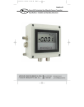
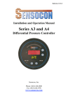
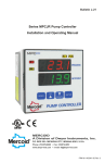
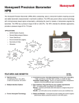
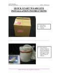
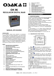
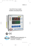
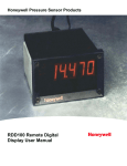
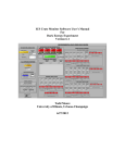
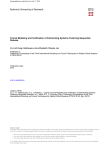
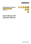
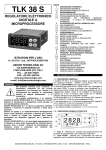
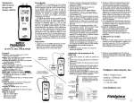
Bulletin B-31 Series DHII Digihelic® II Differential Pressure Controller Specifications - Installation and Operating Instructions DWYER INSTRUMENTS, INC. Phone: 219/879-8000 www.dwyer-inst.com P.O. BOX 373 • MICHIGAN CITY, IN 46361, U.S.A. Fax: 219/872-9057 e-mail: [email protected] DIMENSIONS 4-23/32 [120] 1-31/64 [37.62] 1-1/2 [38.35] 3-7/16 [87.12] ! 4-23/32 [120] 1-45/64 [43.18] 2-23/64 [59.94] 1-17/32 [38.61] 1-5/16 [33] 1-45/64 [43.18] 45/64 [17.78] 1-1/16 [26.97] MOUNTING HOLE PATTERN 4X Ø3/16 [4.76] CLEARANCE HOLES FOR MOUNTING 3-17/64 [83] 1-7/8 [47.5] 4-1/8 [105] OPTIONAL A-438 BRACKET MOUNTING DIAGRAM 4-9/64 [105.17] WIRING TERMINAL ACCESS 8-36 FLAT HEAD SCREWS ! 5-7/32 [132.56] #8 LOCK WASHER DO NOT REMOVE THESE SCREWS TO GAIN ACCESS TO WIRING TERMINALS, REMOVE THESE TWO SCREWS AND “FLIP” DISPLAY 90° DO NOT REMOVE THE SCREWS WITH] POWER APPLIED TO INSTRUMENT WIRING TERMINALS HINGED STANDOFF 1 SPECIFICATIONS Service: Air and non-combustible, compatible gases. Wetted Materials: Consult factory. Housing Material: Aluminum, glass. Accuracy: ±0.5% at 77°F (25°C) including hysteresis and repeatability (after 1 hour warm-up). Stability: < ±1% per year. Pressure Limits: Ranges ≤ 2.5 in. w.c. = 2 psi 5˝: 5 psi; 10˝: 5 psi; 25˝: 5 psi; 50˝: 5 psi; 100˝: 9 psi. Temperature Limits: 32 to 140°F (0 to 60°C). Compensated Temperature Limits: 32 to 140°F (0 to 60°C). Thermal Effects: 0.020%/°F (0.036/°C) from 77°F (25°C). Power Requirements: High Voltage Power = 100 to 240 VAC, 50 to 400 Hz or 132 to 240 VDC. Low Voltage Power = 24 VDC ±20%. Power Consumption: Low Voltage Power = 24 VDC - 130 mA max. High Voltage Power = 100 to 240 VAC, 132 to 240 VDC - 7VA max. Output Signal: 4-20 mA DC into 900 ohms max. Zero & Span Adjustments: Accessible via menus. Response Time: 250 ms (dampening set to 1). Display: 4 digit backlit LCD 0.6˝ height. LED indicators for set point and alarm status. Electrical Connections: Euro type removeable terminal blocks with watertight conduit fittings for 1/2˝ watertight conduit. Process Connections: 1/8 female NPT. Enclosure Rating: Designed to meet NEMA 4 (IP66). Mounting Orientation: Mount unit in horizontal plane. Size: 4.73˝ x 4.73˝ x 3.43˝ (120 mm x 120 mm x 87.1 mm). Weight: 2 lb 10 oz (1.19 kg). Serial Communications: Modbus® RTU, RS485, 9600 Baud. Agency Approvals: UL & CE. SWITCH SPECIFICATIONS Switch Type: 2 SPDT relays. Electrical Rating: 8 Amps at 240 VAC resistive. Set Point Adjustment: Adjustable via keypad on face. Modbus® is a registered trademark of Schnieder Automation. 2 WIRING CONNECTOR ON LOWER BOARD 1 2 3 6 7 C 3/8 A 250vac MEDIUM LAG 100-240 VAC or 132-240 VDC POWER NOTE 1 5 4 N/O CONNECTOR ON UPPER BOARD 8 1 2 3 4 5 6 7 8 A- RS485 SERIAL B+ COMMUNICATION C N/C SP1 RELAY N/O + 24 VDC POWER - NOTE 1 N/C REMOTE SWITCH SP2 OR ALARM RELAY + 4-20mA TRANSMITTER OUTPUT - RESET Device receiving 4-20mA signal. Check specifications of this device for input load resistance. Typical 250 to 600 OHMS, 900 OHMS maximum. WARNING If Digihelic® II Controller is powered by 24 VDC, the device receiving the 4-20 mA transmitter output MUST NOT share a common ground with the 24 VDC supply or damage to the Digihelic® II Controller will result. NOTES: 1. The instrument may be powered from the AC line or 24 VDC. Do not wire AC line terminals 1-2 on the lower board and 24 VDC terminals 4-5 on the upper board at the same time or damage to the unit will result. 2. For supply connections, wire in accordance with an equivalent national standard or code. Use copper conductors only rated for at least 75°C. 3. Terminals on upper board are rated CLASS 2. 4. ISOLATION: Relays - 1500 VAC to all other inputs and outputs. AC Line Power (terminals 4-5) - 1500 VAC to all other inputs and outputs. RS485 output - 500 VAC to all other CLASS 2 wiring. The 24 VDC Power, 4-20 mA transmitter, and Remote Reset Switch share a common ground. 5. The Remote Reset Switch must be a dry contact switch. 6. Shielded cable is required for RS485 wiring. 3 When wiring the instrument, you must follow industry standard practice for control and protection against Electro-Static Discharge (ESD). Failure to exercise good ESD practices may cause damage to the control. WIRING 1. Remove cover. 2. To gain access to the wiring terminal blocks, remove the upper and lower screws toward the center of the display board, and then flip the display board up at a 90° angle. 3. Wire to the two terminals blocks as shown in the wiring diagram. NOTE: Depending on the application, it may be only necessary to wire to the smaller terminal block on the upper board. In that case one of the liquid tight fittings may be removed and replaced with the provided rubber plug. 4. For liquid tight applications, use only 1/2˝ liquid tight conduit. 5. When wiring is complete, reverse steps 2 and 1. Make sure the cover is properly tightened to the housing. DIGIHELIC® II CONTROLLER RS485 WIRING DIGIHELIC - RS485 WIRING TO DAISY CHAIN INSTRUMENTS UP TO 128 UNITS MAY BE DAISY CHAINED ON THE RS485 BUSS LAST UNIT ON RS485 BUSS CONNECTOR ON LOWER BOARD 1 2 3 4 5 6 CONNECTOR ON LOWER BOARD CONNECTOR ON UPPER BOARD 7 8 1 1 2 3 4 5 6 7 8 2 3 4 5 6 CONNECTOR ON LOWER BOARD CONNECTOR ON UPPER BOARD 7 8 1 2 3 4 5 6 7 8 SHIELD SHIELD WIRE NUT 1 2 3 4 5 6 CONNECTOR ON UPPER BOARD 7 8 1 2 3 4 5 6 7 8 120 OHM RESISTOR TIE SHIELD TO EARTH GROUND TO RS232 TO RS485 CONVERTER THE 120 OHM RESISTOR IS USUALLY ONLY NECESSARY FOR LONG WIRE RUNS. INSTALLATION Mount the instrument in a location that will not be subject to excessive temperature, shock or vibration. Pressure Connections Use 1/8 male NPT fittings. When tightening fittings, grasp the brass fitting on the Digihelic® II Controller with a 1/2˝ wrench to prevent the fitting on the Digihelic® II Controller from turning. 4 MULTIPLIER DESCRIPTOR VISIBLE WITH SOME VELOCITY AND FLOW RANGES FRONT PANEL X1K UNITS 99.99 SP1 DESCRIPTOR SP2 DESCRIPTOR SCFM SP1 SP2 ALLO ALHI SP/AL MENU E RST PROCESS VALUE HIGH ALARM DESCRIPTOR LOW ALARM DESCRIPTOR KEY FUNCTIONS SP/AL SP/AL SP/AL SP/AL SP/AL SP/AL SP/AL MENU MENU MENU MENU MENU MENU HOME POSITION FUNCTION MAIN MENU FUNCTION SUB MENU FUNCTION Sequences the display through SET POINT and ALARM settings Return to home position Return to home position Allows access to the menus Return to home position Return to previous menu Sequences through menus Increments a value Sequences through menus Decrements a value Enter into SUB MENU Changes a value or setting. Press ENTER and display will blink. Adjust with UP or DOWN arrows. Press ENTER to store. Display will stop blinking. MENU UP ARROW E E E E E ENTER DOWN ARROW Displays full scale range of unit RST RST RST RST RST RST RESET Clears or resets an Alarm (alarm set for manual reset) Peak/Valley SUB MENU resets display to present value. 5 SETTING SET POINTS AND ALARMS The SP/AL hot key provides direct access to the Set Point and Alarm MENU. The Set Point and Alarm MENUS that are displayed are based upon the Control (CtrL) SUB MENU. CONTROL MODE CONTROL MODE CONTROL MODE SP/AL SP/AL SP/AL SP/AL SP/AL SP/AL SP/AL SP/AL SP/AL SP/AL SP/AL SP/AL SP/AL Visible when mode = Visible when mode = Visible when mode = SET POINT ADJUSTMENT Adjusting the Digihelic® II Controller Set Points is quick and simple. Instead of setting a set point and deadband, simply adjust SP1H or SP2H for the desired relay turn on point, and then adjust SP1L or SP2L for the desired relay turn off point. 1.0 0.8 0.6 PRESSURE (in. w.c.) 0.4 0.2 0 0 TIME In the above graph, an instrument with a 1.0˝ range would have the SP1 relay turn on at 0.8˝ and off at 0.4˝. SP1H sets the relay turn on point, and SP1L sets the relay turn off point. The relays outputs normally function in the direct acting mode, which means the relays turn on with an increase in pressure. SP1 may be configured to act as a reverse acting relay (refer to the 1SP SUB MENU setting, page 15). When set for reverse acting, SP1H sets the relay turn OFF point, and SP1Lsets the relay turn ON point. SP2 is always direct acting. 6 MENU MAP MAIN MENUS SUB MENUS SETTINGS SP/AL SP/AL MENU MENU E E MENUS UNAVAILABLE FOR BI-DIRECTIONAL RANGES AND RANGES ABOVE 25 IN. W.C. RST RST SP/AL MENU SP/AL CONTINUED E MENU 7 MAIN MENUS SETTINGS SUB MENUS SP/AL SP/AL MENU MENU E E SP/AL RST RST MENU CONTINUEDSP/AL E MENU 8 SP/AL MAIN MENUS SETTINGS SUB MENUS SP/AL Menus present only in pressure operation MENU MENU E E SP/AL RST MENU RST SP/AL E MENU RST E 9 Main Menu Selections (Upper Right Display Reads MENU ) SECr Security - Lock out access to Set Point and Alarm settings, or lock out access to all settings. OPEr Operation - Selection of Pressure, Velocity or Flow and corresponding engineering units. OUt Output - Select a Single Set Point, 2 Set Points, or a Set Point and an Alarm mode of operation. d.S Display - Monitor and adjust display related settings: Peak, Valley, display resolution, % output and dampening. AdU Advanced functions - Modify advanced function parameters, transmitter output scaling, Modbus® communication settings, Maintenance Set Point settings and calibration. 10 MAIN MENUS and SUB MENUS SECr (Security) MAIN MENU SECr is the only SUB MENU in the security MENU. When the security SUB MENU is selected, the present security level is displayed in the upper right hand display. To change the security level, adjust the number displayed to the number shown in the following table for the desired security level. Security Level Displayed Access Password Value to Enter 1 All menus access 10 2 Menu Access SP/AL Locked 70 3 SP/AL Access Menus Locked 90 4 All settings locked 111 The password values shown in the table cannot be altered, so retain a copy of these pages for future reference. OPEr (Operation) MAIN MENU The OPEr MENU selects the measurement type of the instrument. The SUB MENUS are: PrES - Pressure KFAC - K Factor XDIM - X Dimension UEL - Velocity ArEA - Area YDIM - Y Dimension FLO - Flow DIA - Diameter OPEr MENU will have an additional KFAC SUB MENU. If the instrument is set for Flow, the OPEr MENU will have additional KFAC and ArEA SUB MENUS. These will be discussed under Velocity and Flow. When scrolling through the OPEr SUB MENUS, the measurement type the unit is If the instrument is set for Velocity, the currently set for will show the units in the upper right display. The other measurement types will have a blank upper right display. Units visible, so unit is presently set to measure pressure Units not visible 11 Units not visible PrES (Pressure) SUB MENU For pressure measurement, the following units are available: INWC - Inches of water column FTWC - Feet of water column MMWC - Millimeters of water column CMWC - Centimeters of water column PSI - Pounds per square inch INHG - Inches of mercury MMHG - Millimeters of mercury MBAR - Millibar PA - Pascal KPA - Kilopascals HPA - Hectopascals OZIN - Ounce inches Table 1 Pressure Range vs. Available Units INWC FTWC MMWC CMWC .1000 .2500 .5000 1.000 2.500 5.000 10.00 25.00 50.00 100.0 .2083 .4167 .8333 2.083 4.167 8.333 2.540 6.350 12.70 25.40 63.50 127.0 254.0 635.0 1270 2540 .2540 .6350 1.270 2.540 6.350 12.70 25.40 63.50 127.0 254.0 PSI INHG MMHG MBAR .1806 .3613 .9032 1.806 3.613 .1868 .4671 .9342 1.868 4.671 9.342 18.68 46.71 93.42 186.8 .1839 .3678 .7356 1.839 3.678 7.356 .2491 .6227 1.245 2.491 6.227 12.45 24.91 62.27 124.5 249.1 PA 24.91 62.27 124.5 249.1 622.7 1245 2491 6227 KPA HPA OZIN .1245 .2491 .6227 1.245 2.491 6.227 12.45 24.91 .2491 .6227 1.245 2.491 6.227 12.45 24.91 62.27 124.5 249.1 .1445 .2890 .5780 1.445 2.890 5.780 14.45 28.90 57.80 NOTE: OVFL(over flow) or UnFL(under flow) will appear when the ranges have been exceeded above or below full scale by 2%. UEL (Velocity) SUB MENU For velocity measurement, the following units are available: SFPM - Standard feet per minute M/S - Meters per second Table 2 Available Velocity Ranges INPUT RANGE INWC SFPM RANGE 0 - 0.1 0 - 0.25 0 - 0.5 0-1 0 - 2.5 0-5 0 - 10 0 - 25 0 - 1266 0 - 2002 0 - 2832 0 - 4004 0 - 6332 0 - 8954 0 - 12.66 x IK 0 - 20.02 x IK M/S RANGE 0 - 6.431 0 - 10.17 0 - 14.39 0 - 20.35 0 - 32.17 0 - 45.48 0 - 64.33 0 - 101.7 NOTE: Air velocity and flow readings are based upon standard dry air conditions with an ambient temperature of 70°F and a barometric pressure of 29.92 INHG. 12 FLO (Flow) SUB MENU For flow measurements the following units are available: SCFM - Standard cubic feet per minute M^3H - Cubic meters per hour FLO r (Flow Range) SUB MENU LO - 99.99 x 1K flow range HI - 999.9 x 1K flow range Tables 3 -6 show the flow ranges available, and the maximum duct size that can be set for each input range. Table 3 Table 4 FLOr = LO Maximum Duct Size (English) FLOr = HI Maximum Duct Size (English) RANGE IN WC 0.1 0.25 0.5 1 2.5 5 10 25 SCFM RANGE 99.99 99.99 99.99 99.99 99.99 99.99 99.99 99.99 x x x x x x x x 1K 1K 1K 1K 1K 1K 1K 1K MAX. DUCT SIZE, SQ. FT. RANGE IN WC 78.9 49.9 35.3 24.9 15.7 11.1 7.8 4.9 0.1 0.25 0.5 1 2.5 5 10 25 SCFM RANGE 999.9 999.9 999.9 999.9 999.9 999.9 999.9 999.9 x x x x x x x x 1K 1K 1K 1K 1K 1K 1K 1K MAX. DUCT SIZE, SQ. FT. 789.8 499.5 353.1 249.7 157.9 111.7 78.9 49.9 Table 5 Table 6 FLOr = LO Maximum Duct Size (Metric) FLOr = HI Maximum Duct Size (Metric) RANGE IN WC 0.1 0.25 0.5 1 2.5 5 10 25 Mˆ3/Hr RANGE 99.99 99.99 99.99 99.99 99.99 99.99 99.99 99.99 x x x x x x x x 1K 1K 1K 1K 1K 1K 1K 1K MAX. DUCT SIZE Mˆ2 RANGE IN WC 4.32 2.73 1.93 1.37 0.86 0.61 0.43 0.27 0.1 0.25 0.5 1 2.5 5 10 25 Mˆ3/Hr Range 999.9 999.9 999.9 999.9 999.9 999.9 999.9 999.9 x x x x x x x x 1K 1K 1K 1K 1K 1K 1K 1K MAX. DUCT SIZE, Mˆ2 43.19 27.31 19.3 13.64 8.63 6.10 4.31 2.73 KFAC SUB MENU KFAC K Factor - becomes accessible if the instrument is set for Velocity or Flow. When the Digihelic® II Controller is used with a pitot tube, the manufacturer may specific a K Factor. The adjustment range is 0.01 to 2.00. The factory setting is 1. 13 ArEA, DIA, XDIM and YDIM SUB MENUS These SUB MENUS become accessible if the instrument is set for flow. When measuring flow, the area of the duct must be specified. Tables 3 and 4 show the input range vs maximum flow and duct size. For a rectangular duct the maximum size is specified in square feet or meters. For a circular duct the maximum size is specified as the diameter. X, Y and circular dimensions are entered in feet with 0.01 foot resolution for FLOr = LO and 0.1 foot resolution for FLOr = HI, or entered in millimeters with 1 millimeter resolution. ArEA - Area, select CIR for a circular duct or RECT for a rectangular duct. If a circular duct is selected, the DIA SUB MENU will be activated. If a rectangular duct is selected, the XDIM and YDIM SUB MENUS will be activated. DIA - Diameter, enter the diameter of a duct XDIM - Enter the “X” dimension of a duct YDIM - Enter the “Y” dimension of a duct Y X OUt (Output) MAIN MENU The OUt MENU selects the output type of the instrument. The SUB MENUS are: CtrL- Control type ISP - SP1 reverse or direct acting AL - Alarm type ALrE - Alarm reset, manual or auto AL.H - Alarm inhibit ALDL - Alarm delay 14 CtrL (Control) SUB MENU 1SP - Single set point 2SP - Two fully independent set points SPAL - Single set point and alarm 1SP (SP1 Reverse or Direct Acting) SUB MENU DIR - Direct. Relay turns on with increasing pressure REV - Reverse. Relay turns on with decreasing pressure Direct Acting 100 Process SPH SPL 0 Time Relay Inactive Relay Active Reverse Acting 100 Process SPH SPL 0 Time Relay Inactive Relay Active 15 The following alarm function SUB MENUS are activated when CtrL is set to SPAL: AL (Alarm Type) SUB MENU HI - High alarm LO - Low alarm HILO - For a high/low guardband type alarm ALARM ADJUSTMENT Alarm settings are dependent upon the selected alarm mode. The Digihelic® II Controller alarm may be configured as a High Alarm, Low Alarm, or High/Low Alarm. Alarm settings are all absolute and may be set to anywhere within the range of the instrument. The dead bands of the alarms are fixed at 1% of full scale. HIGH ALARM FUNCTION ALHI MIN. PRESSURE MAX. PRESSURE Relay OFF ALLO Relay ON LOW ALARM FUNCTION MIN. PRESSURE MAX. PRESSURE Relay ON Relay OFF ALHI ALLO HIGH/LOW ALARM FUNCTION MIN. PRESSURE MAX. PRESSURE Relay ON Relay OFF 16 Relay ON ALrE (Alarm Reset) SUB MENU ONOF - Automatic reset HOLD - Manual reset. An alarm is reset by the RESET key on the front panel, or an external reset switch. AL.H (Low Alarm Inhibit) SUB MENU ON - Alarm inhibit is on OFF - Alarm inhibit is off If AL.H is selected ON, a low alarm condition is suspended upon power up until the process value passes through the alarm set point once. ALDL (Alarm Delay) SUB MENU Sets the amount of time an alarm condition must be continuously met before the alarm condition is recognized. The alarm delay is adjustable from 0-3600 seconds. d.S (Display) MAIN MENU PEAK - Peak value VALy - Valley value ZERO - Zero rESO - Resolution Pd.S - Process display DAMP - Dampening level PEAK (Peak) SUB MENU The Peak feature stores the highest pressure reading the instrument has measured since the last reset or power up. At power up PEAK is reset to the present pressure reading. To manually reset the PEAK value, press the RESET key while in the PEAK SUB MENU. VALy (Valley) SUB MENU The valley feature stores the lowest pressure reading the instrument has measured since the last reset or power up. At power up VALy is reset to the present pressure reading. To manually reset the VALy value, press the RESET key while in the VALy SUB MENU. 17 rESO (Resolution) SUB MENU The Digihelic® II Controller is capable of displaying four digits of resolution. However, at very low pressures the instability of the pressure may cause fluctuations in the least significant digit causing the least significant digit to be of little value. Three digit resolution (3DIG) can only be active when there is at least one digit to the right of a decimal. 3DIG - Set display for 3 digit resolution 4DIG - Set display for 4 digit resolution Pd.S (Process Display) SUB MENU STD - Display reads pressure, velocity, or flow values PCT - Display reads % of full scale value When the display is reading percent, PCT is displayed in the upper right of the display. The percent display is only available in pressure operation. DAMP (Dampening) SUB MENU Adjust from 1-16 Dampening stabilizes the display from instabilities due to things such as vibration and excessive pressure fluctuations. The dampening setting adjusts the amount of readings that are averaged for each display update. Adjust the dampening value until the display reads a stable value for the application. AdU (Advanced) MAIN MENU POL - Process output low POH - Process output high MSP1 - Maintenance set point 1 MSP2 - Maintenance set point 2 ADDR - Modbus® address WR - Modbus® write enable/disable ZERO - Zero calibration SPAN - Span calibration POL and POH (Process Output Low and High) SUB MENUS This feature is used in pressure operation only. Process output low and high are used to scale the 4-20 mA output. Set POL to the desired display reading for 4mA output, and set POH to the desired display reading for 20 mA output. POH must be higher than POL. POL may be adjusted 2% BELOW minimum scale up to POH. POH may be adjusted from POL to 2% ABOVE maximum scale. 18 MSP1 and MSP2 (Maintenance Set Point 1 & 2) SUB MENUS Adjust for the desired maintenance set points when the unit is placed in the maintenance mode. The deadband is fixed at 2% of full scale. To enter or leave the maintenance mode, press and hold the SP/AL for 8 seconds. ADDR (Modbus® Address ) SUB MENU Modbus® communication instrument address. Set from 1 to 247. This number must match the address number used by the MENU host computer. To obtain the Digihelic® II Controller Modbus® register list please visit www.dwyer-inst.com See page 4 for wiring diagram. WR (Modbus® Write Protect) SUB MENU d.S - Disables write commands from Modbus®. Modbus E ® can only read information from the instrument. En - Enable write commands from Modbus®. Modbus® can read information from and write information to the instrument. ZERO and SPAN (Calibration of Zero and Span) SUB MENUS RST The lower display reads CAL in this mode. ZERO Calibration NOTE: For accurate calibration, DO NOT apply any pressure when performing this function. With the display reading ZERO, press the ENTER key. The upper display will blink. Press ENTER again to complete the zeroing of the instrument or press the MENU key to cancel. SPAN Calibration With the display set to SPAN, apply full scale pressure to the unit. Press the ENTER key. The upper display will blink. Press ENTER again to complete the calibration or press the MENU key to cancel. ©Copyright 2007 Dwyer Instruments, Inc. Printed in U.S.A. 11/07 FR# 19-443434-00 Rev. 2 DWYER INSTRUMENTS, INC. Phone: 219/879-8000 www.dwyer-inst.com P.O. BOX 373 • MICHIGAN CITY, IN 46361, U.S.A. Fax: 219/872-9057 e-mail: [email protected]