1
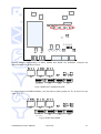
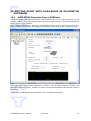
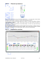
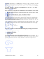
AVA4-ES100
USER’S M A NUAL
AVA4-ES100 User‟s Manual
AuviTran
1
TABLE OF CONTENTS
1-
WELCOME! .................................................................................. 3
2-
ELECTRICAL AND ELECTRONIC INTERFERENCES..................................... 4
3-
LIMITATION OF LIABILITY .............................................................. 5
4-
TRADEMARKS............................................................................... 5
5-
COPYRIGHT ................................................................................. 5
6-
AUVITRAN WEBSITE / MORE INFORMATION ........................................ 5
7-
PACKAGE CONTAINS ...................................................................... 5
8-
PRECAUTIONS.............................................................................. 6
9-
TECHNICAL SPECIFICATIONS OF THE DEVICE ..................................... 7
10- MECHANICAL OUTLINES ................................................................. 8
11- AVA4-ES100 REAR PANEL .......................................................... 10
11-1- AVA4-ES100 DC Power version ................................................ 10
11-2- AVA4-ES100 AC Power version................................................. 10
11-3- Wiring ..................................................................................... 10
12- ARCHITECTURE USING AVA4-ES100 ............................................. 11
13- HARDWARE MODE SELECTION ........................................................ 12
13-1- Maximum Input Level for 0 dBFs .............................................. 13
13-2- Phantom power supply ............................................................ 14
13-3- GPIO connector configuration .................................................. 16
14- SOFTWARE DOWNLOAD AND INSTALLATION ...................................... 18
15- GETTING START WITH AVA4-ES100 IN ES-MONITOR SOFTWARE ........ 19
15-1- AVA4-ES100 Properties Page in ESMonitor ............................... 19
15-2- AVA4-ES100 Control Page in ESMonitor .................................... 20
15.2.1 Channels parameters ...................................................................... 21
15.2.2 Equalisation window ....................................................................... 21
15.2.3 “Link” button .................................................................................. 23
15.2.4 GPIO Setup and Status.................................................................... 24
AVA4-ES100 User‟s Manual
AuviTran
2
1- WELCOME!
Thank you for purchasing AuviTran‟s AVA4-ES100 device. We hope you will enjoy using
it. AVA4-ES100 is a configurable EtherSound analog audio interface with 2 balanced
analog audio inputs, 2 balanced analog audio outputs and a SPDIF digital audio output.
AVA4-ES100 is a full ES100 compatible device and can be used without any restriction in
any kind of ES100 network. AVA4-ES100 audio input sensitivity configuration enable a
wide range of use from line input up to microphone input. Built-in AVA4-ES100
parametric equalizers and gain control on all inputs and outputs allow audio quality and
intelligibility control in any environment. AVA4-ES100 is ideal for Public Address and wide
distributed digital professional sound network systems.
A set of 4 GPI and 4 GPO makes the AVA4-ES100 locally or remotely controllable.
Moreover AVA4-ES100 integrates a configurable RS232 serial interface. AVA4-ES100
embeds AuviTran virtual tunneling mechanism for connecting its local RS232 to another
remote serial interface of an AuviTran or Yamaha ES100 device.
You will find herewith the necessary instructions to install your device. Please read them
carefully as misuse of this device might cause serious damage to you and your
environment.
AVA4-ES100 User‟s Manual
AuviTran
3
2- ELECTRICAL AND ELECTRONIC INTERFERENCES
This device complies with Part 15 of the FCC rules. Operation is subject to the following
two conditions:
1. This device may not cause harmful interference.
2. This device must accept any interference received including interference that may
cause undesired operation.
FCC INFORMATION (U.S.A.)
1. IMPORTANT NOTICE: DO NOT MODIFY THIS UNIT!
This product, when installed as indicated in the instructions contained in this manual, meets FCC
requirements. Modifications not expressly approved by Yamaha may void your authority, granted by the
FCC, to use the product.
2. IMPORTANT: When connecting this product to accessories and/or another product use only high
quality shielded cables. Cable/s supplied with this product MUST be used. Follow all installation instructions.
Failure to follow instructions could void your FCC authorization to use this product in the USA.
3. NOTE: This product has been tested and found to comply with the limits for a Class B Digital device,
pursuant to Part 15 of the FCC Rules. These limits are designed to provide reasonable protection against
harmful interference in a residential environment. This equipment generates, uses and can radiate radio
frequency energy and, if not installed and used according to the instructions found in the users manual, may
cause interference harmful to the operation of other radio communications.
Compliance with FCC
regulations does not guarantee that interference will not occur in all installations. If this product is found to
be the source of interference, which can be determined by turning the unit “OFF” and “ON”, please try to
eliminate the problems by using one of the following measures:
Relocate either this product or the device that is being affected by the interference.
Utilize power outlets that are on different branch (circuit breaker or fuse) circuits or install AC line
filter(s).
In the case of radio or TV interference, relocate/reorient the antenna. If the antenna lead-in is 300
ohm ribbon lead, change the lead-in to co-axial type cable.
If these corrective measures do not produce satisfactory results, please contact the local retailer authorized
to distribute this type of product. If you cannot locate the appropriate retailer, please contact Yamaha
Commercial Audio Systems, Inc., Electronic Service Division, 6600 Orangethorpe Ave, Buena Park,
CA90620.
The above statements apply ONLY to those products distributed by Yamaha Commercial Audio Systems, Inc.
or its subsidiaries.
COMPLIANCE INFORMATION STATEMENT
(DECLARATION OF CONFORMITY PROCEDURE)
Responsible Party :
Address :
Telephone :
Type of Equipment :
Model Name :
Yamaha Commercial Audio Systems, Inc.
6600 Orangethorpe Ave.,
Buena Park, Calif. 90620
714-522-9011
EtherSound Analog Audio Interface
AVA4-ES100
This device complies with Part 15 of the FCC Rules.
Operation is subject to the following conditions:
1) This device may not cause harmful interference, and
2) This device must accept any interference received including
interference that may cause undesired operation.
See user manual instructions if interference to radio reception is
suspected.
AVA4-ES100 User‟s Manual
AuviTran
4
3- LIMITATION OF LIABILITY
In no case and in no way, the provider of this device (AuviTran, the distributor or
reseller, or any other party acting as provider) shall be liable and sued to court for
damage, either direct or indirect, caused to the user of the device and which would result
from an improper installation or misuse of the device. “Misuse” and “improper
installation” mean installation and use not corresponding to the instructions of this
manual.
Please note that graphics given in this manual (drawings and schemes) are only
examples and shall not be taken for a real vision of your own equipment configuration.
AuviTran is constantly working on the improvement of the products. For that purpose,
the products functionalities are bound to change and be upgraded without notice. Please
read carefully the User‟s manual as the new functionalities will be described therein.
4- TRADEMARKS
All trademarks listed in this manual are the exclusive property of their respective owners.
They are respected “as is” by AuviTran. Any use of these trademarks must receive prior
approval of their respective owners. For any question, please contact the trademark‟s
owner directly.
5- COPYRIGHT
The information in this manual is protected by copyright. Therefore, reproduction,
distribution of whole or part of this manual is strictly forbidden without the prior written
agreement of AuviTran.
6- AUVITRAN WEBSITE / MORE INFORMATION
Please visit our website for any question of further inquiry concerning our product range.
Updates will also be posted when available.
http://www.AuviTran.com
7- PACKAGE CONTAINS
1
1
1
1
4
2
1
AVA4-ES100 device
power line connector (2 pins, 3.81 mm step) for DC power supply version
cord set for AC power supply version
power supply connector (2 pins,3.81 mm step) for DC power supply
analog inputs and outputs connectors (3 pins, 3.81 mm step)
GPIO connectors (6 pins, 3.81 mm step)
metal hook for security sling attach
AVA4-ES100 User‟s Manual
AuviTran
5
8- PRECAUTIONS
Do not modify or disassemble the board. The guarantee shall be null and void in that
case. Do not apply excessive pressure on connectors or any other part of the board. Do
not touch the metallic sharp parts (pins) of the board. This board is electrostatic
sensitive; make sure you check this before touching or using it. Few parameters are
internal jumpers selectable. Please carefully read referring paragraph before opening the
device. In any case, always unplug the main power cord of the device, and wait few
seconds that all LED are off before opening the device.
AVA4-ES100 User‟s Manual
AuviTran
6
9- TECHNICAL SPECIFICATIONS OF THE DEVICE
General
Size
1/3 of 1U 19’’ rack : 145 mm x 40 mm x 203mm
Power Consumption
5 Watts
Power Supply
12VDC 0.4 A or 100-240VAC
Storage: Temp/Humidity
- 5°C to 70°C / 0% to 95% (non-condensing)
Operating: Temp/Humidity
0 °C to 50°C / 5% to 90% (non-condensing)
Connectors
1x2 pole Euroblock connector (pitch 3.81 mm) for DC power supply; 2x3 pole double row Euroblock connector (pitch
3.81mm) for analog inputs and outputs; 1x6 pole double row Euroblock Connector (pitch 3.81mm) for GPIO. 2x RJ45
connectors for network connections
Audio Inputs and Outputs
Number of i/o
Number of inputs
Number of outputs
Up to 4 mono audio inputs and/or outputs software selectable (2xAin+2xAout, 2xAin+1xSPDIF, 2xAout+1xSPDIF)
2 Analog Inputs Inserted in any of the 128xEtherSound™ channels(64 upstream or 64 downstream)
2 Analog Outputs , 1 SPDIF output (Stereo)
extracted from any of the 128xEtherSound™ channels(64 upstream or 64 downstream) (1) (2)
(1) SPDIF o u t p u t r ep lace s GPO2 b y ju m p e r se lect i o n (2) Wh en o n ly 2 o u t p u t s SPDIF an d an alo g o u t p u t p lay t h e sam e Et h er So u n d
ch an n els (3) Se r ial p o r t r ep lace s GPO3 & 4 b y ju m p er select io n
Audio Specifications
Sampling Frequency
A/D an d D/A
r eso lu t io n
Frequency response
Dynamic Range
Total harmonic Distorsion
Input Specification
Output Specification
44.1 kHz / 48 kHz
24 bits
20Hz – 20Khz @ +/- 0.2 dB
>100dB
<-95dB
Balanced analog, +22dBu, +10dBV or -44dBu (jumper), <100 Ω Impedance – 12V Phantom power available for
microphone
Servo-balanced, +22dBu, 22,2 kΩ Impedance, 127dB/1dB step digital attenuator
GPIO Specifications
GP In
GP Out
Serial interface
4x Opto-isolated. +60Vdc maximum input voltage.
4x +60Vdc/1A open drain Darlington per GPO. Internal +12Vdc available (100mA max).
RS232 Rx/Tx serial port interface (3)
Development and Integration Environment
OS Supported
AVS-ESMonitor
Development Tools
Windows 32 bits Vista/XP
AVS-ESMonitor enables to remotely set, control and monitor an EtherSound network and provides enhanced control
pages to manage the AVA4-ES100 specific parameters.
PC Telnet based development tools allowing access and control of all of the EtherSound devices devices' parameters.
AVA4-ES100 User‟s Manual
AuviTran
7
10- MECHANICAL OUTLINES
AVA4-ES100 User‟s Manual
AuviTran
8
AVA4-ES100 User‟s Manual
AuviTran
9
11- AVA4-ES100 REAR PANEL
AVA4-ES100 is available with DC and AC power version.
11-1- AVA4-ES100 DC Power version
11-2- AVA4-ES100 AC Power version
11-3- Wiring
Screen-print on the top box cover illustrates how to wire device:
Pins L+ (positive Left) and R+ (positive Right) are positive analog in/outputs
while L- (negative Left) and R- (negative Right) are negative analog
in/outputs. G is the ground (0V).
In GPI and GPO connectors, one Ground pin and one
+12V pin are available per connector. GPIO
configuration is explained in chapter 13.3.
AVA4-ES100 User‟s Manual
AuviTran
10
12- ARCHITECTURE USING AVA4-ES100
Here is a typical architecture using AVA4-ES100 associated with others EtherSound
products.
Cat5 without audio
Ethersound over Cat5 cable
This architecture is typical for audio distribution in theatre lodges, VIP rooms …
AVM500-ES (primary master) receives digital audio signal from digital console over
Ethersound thanks to AVY16-ES100, and sends it to AVA4-ES100. Using ES-Monitor, you
can send custom audio to each room with different parameters (equalization, gain…)
depending on characteristics of each room.
AVA4-ES100 User‟s Manual
AuviTran
11
13- HARDWARE MODE SELECTION
Some of the AVA4-ES100 functionality are only hardware configurable. Standard jumpers
are used to select appropriate function. Theses functions are divided in three groups:
- Maximum input level for 0 dBFs (+22dBu, +10dBu, -44dBu)
- +12V Phantom power supply
- GPIO connector configuration
Phantom power supply configuration is made of for two-point pin headers. GPIO
configuration is made of one line of seven three-point pin headers. Maximum input level
for 0 dBFs configuration is made of three groups of two two-point pin headers. You will
find below a picture of the AVA4-ES100 board, to help find these pin headers.
Warning: This unit contains hazardous voltages. Access to these pin
headers is only possible by opening the device. Please ensure that
power supply source is unplugged and that all LED are off before
opening the device. Do never open the device if power supply cord is
plugged.
AVA4-ES100 User‟s Manual
AuviTran
12
13-1- Maximum Input Level for 0 dBFs
Schematic below helps you to locate where the pins are. You can also notice that there is
a space between each pair to avoid confusion when trying to put the jumper on the pins.
Factory default configuration is +22dBu. Jumpers are delivered separately with the
product. You can unplug jumpers or put only on one pin of each pin header (Fig. 1).
Following schematics represent three available configurations for identical settings for left
and right channel. Note that different settings can be set for left and right channels.
J3
J3
J3
r
r
r
J4
J1
J4
J4
J2
Fig.1 : +22dBu
AVA4-ES100 User‟s Manual
J1
J2
Fig.2 : +10dBu
AuviTran
J1
J2
Fig.3 : -44dBu
13
Screen-print on the box top cover illustrates how to connect jumpers for each mode
(Fig.4).
Fig.4: Maximum Input Level for 0dBFs
J1 and left side of J3 allow user to set left input channel.
J2 and right side of J3 allow user to set right input channel.
Only these configurations are allowed. If jumpers are set in a different way,
device behaviour is not guaranteed.
13-2- Phantom power supply
Schematic below helps you locating where the pins are. There is a space between each
pair to avoid confusion when trying to put the jumper on the pins.
Factory default configuration is phantom power supply switched off. Jumpers are
delivered with the product separately. You can unplug jumpers or put only on one pin of
each pin header (Fig. 5).
AVA4-ES100 User‟s Manual
AuviTran
14
Following schematics represent two available configurations for identical settings for left
and right channel. Note that different settings can be set for left and right channels.
J3
J3
r
r
J4
J1
J4
J1
J2
Fig.5: Phantom power
supply switched off
J2
Fig.6: Phantom power
supply switched on
The two left side pin header of J4 allow user to switch on/off phantom power left channel.
The two right side pin header of J4 allow user to switch on/off phantom power left
channel.
Screen-print on the box top cover illustrates how to connect jumpers to switch on/off
phantom power supply (Fig.7).
Fig.7: switch on/off phantom power supply
Only these configurations are allowed. If jumpers are set in a different way than
above, device behaviour is not guaranteed.
AVA4-ES100 User‟s Manual
AuviTran
15
13-3- GPIO connector configuration
GPIO connector is made of two lines of six pins. Each line provides four GPIO (one per
pin), a ground pin (0 volt) and a +V pin (+12Vdc). Screen-print on the box top cover
illustrate the wiring of this connector:
When configured as GPIO, all GPI are located on the top line of pins, and all GPO are on
the bottom line. Inputs are opto-isolated. A maximum voltage of +60Vdc, referring to
ground („G‟ pin) is accepted. Outputs are open-drain. A maximum of +60Vdc/1A per
output is accepted.
O1 . . .4 O
+60Vdc/1A max
I1...I4
G
+60Vdc
G
GP Input
GP Output
Two out of four GPIO can be configured to have a dedicated function. This selection is
made thanks to one line of four three-pin headers as previously shown. Dedicated
functions are RS232 signal (Rx, TX), SPDIF output and word clock input. Screen-print
illustrates how to set jumpers in order to choose between GPIO and dedicated function.
Each configuration can be set individually. You can mix GPI, GPO and dedicated functions
to fit your needs. Schematic below shows the pin headers on the board:
AVA4-ES100 User‟s Manual
AuviTran
16
Factory default configuration is GPI3, GPIO4 and SPDIF out available. Jumpers are
delivered with the product (Fig 8).
J4
SPDIF OUT/GPO3
J5
Tx/GPO4
J6
Wclk/GPI3
J7
Rx/GPI4
Fig.8: SPDIF OUT, GPIO3 and GPI3
In order to have all GPIO available, you will have to place jumper J4, J5, J6 and J7 on the
right (Fig. 9).
J4
SPDIF OUT/GPO3
J5
Tx/GPO4
J6
Wclk/GPI3
J7
Rx/GPI4
Fig.9: GPIO3 and GPIO4
AVA4-ES100 User‟s Manual
AuviTran
17
In order to use RS232 port, you will have to place jumper J5 and J7 on the left (Fig.10).
J4
SPDIF OUT/GPO3
J5
Tx/GPO4
J6
Wclk/GPI3
J7
Rx/GPI4
Fig.10: Rx/Tx and GPIO4
In order to use WCLK input, you will have to place jumper J6 on the left (Fig.11).
J4
SPDIF OUT/GPO3
J5
Tx/GPO4
J6
Wclk/GPI3
J7
Rx/GPI4
Fig.11: GPIO3, GPO4 and Word clock input
14- SOFTWARE DOWNLOAD AND INSTALLATION
Please visit our website to download the latest version of our EtherSound Monitor
Software called ESMonitor (http://www.AuviTran.com) and save the file on your
hard disk. ESMonitor requires Windows 2000, XP or Vista to function.
You are now ready for installation. Refer to the ESMonitor documentation for installation.
Once ESMonitor installed on your PC, you can run ESMonitor and manage any
EtherSound devices connected to an EtherSound network. AVA4-ES100 is an EtherSound
device with specific property and control page which is explained below. Refer to the
ESMonitor documentation for generic EtherSound device management such as
Enumeration of EtherSound devices and I/O routing.
AVA4-ES100 User‟s Manual
AuviTran
18
15- GETTING START WITH AVA4-ES100 IN ES-MONITOR
SOFTWARE
15-1- AVA4-ES100 Properties Page in ESMonitor
Computer where EtherSound Monitor was installed should be now connected to the
primary master of the EtherSound network. The primary master is the first EtherSoundbased device of the network.
After running ES-Monitor, select an AVA4-ES100 device on the device list or tree list.
When selected, ES-Monitor will display the following information in the “properties” tab:
This page gives you general indication on device, such as MAC address, firmware and
EtherSound kernel version, number of inputs and outputs available and network quality if
activated.
Please refer to ES-Monitor documentation for a complete description.
AVA4-ES100 User‟s Manual
AuviTran
19
15-2- AVA4-ES100 Control Page in ESMonitor
When control page of selected AVA4-ES100 is activated, ES-Monitor displays:
Basic features are displayed when first selecting the control page. It allows user to have
a quick overview and control access to the device. This interface allows user to:
- See general status of the device (faulty status for instance)
- See and control gain for each channel
- See equalization configured on each channel, ability to turn on or off
- Create control pairs (“link” button)
- See GPIO Setup and Status
AVA4-ES100 User‟s Manual
AuviTran
20
15.2.1
Channels parameters
Each channel has the same set of individual parameters, i.e. accurate gain control (fader
or direct numeric value), real-time vu-meter and equalisation control.
The gain can be set by moving the fader up or down, or directly by typing a numeric
value between +10dB and -117dB. Using wheel mouse over gain slider also allows to
adjust gain step by step.
Real-time vu-meter is a post-fader and post-EQ display. It shows the signal effectively
sent to output or network.
Equalisation control button shows correction applied to the channel. It allows having a
quick view without opening the EQ control window. “ON” button below shows if current
correction is applied or not. You can directly click on it to turn on/off the EQ.
15.2.2
Equalisation window
AVA4-ES100 User‟s Manual
AuviTran
21
When clicking on EQ control button described above, equalisation control window popsup. Each channel has its own equalisation window. Seven parametric filters are available
for each channel. Each filter is represented by a different colour, helping user to quickly
identify which band is currently selected.
Pre and post vu-meters (respectively on left and right) are displayed to help user tuning
filter gain and global gain to the best value without clipping. A clip indicator is also
available for each band, indicating in real time that the applied correction is clipping the
signal.
To allow use of a positive correction (gain) even if the input level is too high, a local
attenuator (“ATT” button) is available. This attenuator will apply a -12dB gain to the
input signal, giving enough headroom for a correction.
Each band control is identical, and detailed below.
Three parameters commonly available on parametric equalizers can be set, i.e. frequency
(F), quality factor (Q) and gain (G). Theses parameters are displayed numerically to
provide an accurate view and control of each band. Of course, direct control on the graph
is possible with the mouse. When the mouse pointer is over the desired point, the colour
bar of associated filter is blinking. This informs user of which band is selected, in case of
two or more points were covering each other. To change correction applied, just click on
the desired point, and drag it over the graph. A horizontal move will change the
frequency, as a vertical move will act on the gain. To change the quality factor, just roll
up or down the wheel mouse.
AVA4-ES100 User‟s Manual
AuviTran
22
Each band has a range of +/-18dB gain. If you want to apply a correction over this
range, you should use two or more bands set on the same frequency. That way, gain of
each band will be added. You can also use the Zoom “+” and “-” button to change graph
scale, if needed.
Clip signal indicates in real-time if signal processed by the filter is over-range. It
illuminates in red when occurs.
Quick configuration for high-pass and low-pass filter is also available by clicking on the
button next to the clip display:
-
This indicates the filter is a standard parametric filter. This is the default setup.
-
First order high-pass filter. Default cut frequency is 100Hz.
-
First order low-pass filter. Default cut frequency is 19 kHz.
“Flat” button allows quick restore for all filters to a flat response. Be aware that this is
not a bypass button. Previously set correction will be lost by clicking on the flat button. If
you want to quickly listen to the signal “with and without” correction, use the “ON”
button to switch equalization on or off.
Fader available in this window is another access to the fader available directly on the
control page. Acting on this fader will act also in real-time the fader of the control page.
15.2.3
“Link” button
This button, available on the basic control page, allows user to create pairs of control, as
a mixing console will do. When channels are linked together, following parameters will be
duplicated:
- fader position (global gain value)
- equalization parameters
- equalization on/off status
- attenuator status
The link button between Output Left and Output Right links these two outputs. This is
exactly the same for the button between Inputs Left and Right.
When clicking on a link button, a window opens, asking the user which channel should
gives its parameters to the other. Simply click again on link button to split the pair.
AVA4-ES100 User‟s Manual
AuviTran
23
15.2.4
GPIO Setup and Status
As shown in chapter 13-3, GPIO connector can be configured to GPIO or dedicated
function. GPIO setup box allows user to inform the software of which mode is selected for
each GPI/GPO. As there is no way for software to detect jumper configuration, this
procedure is needed to display right information.
This box is a real-time control/monitoring of GPIO state. When in GPI mode, each GPI
displays in real-time the state of input with a dark “Off” icon, or a blue “On” icon. When
in GPO mode, each GPO can be turned on or off by clicking on its respective “Set” button.
If GPI/GPO are set to a dedicated function, respective icon in GPIO Status box will
change to “N/A” to inform user that there is no monitoring available.
AVA4-ES100 User‟s Manual
AuviTran
24