1
TABLE OF CONTENTS
DX 2527
SWR
0
1
2
0
2
SET
3
4
6
8 10 12
1
22
10
MIN
OFF
CALIBRATE
MAX
ECHO
R OBOT
Introduction ....................................................................
6
Control & Connections ……………………………………
6
Rear Panel Connectors …………………………………...
10
Microphone …………………………………………………
11
Operation …………………………………………………...
11
Programming. ………………………………………………
12
D U LATI ON
100
40 50
60 70 80 90 ER 9
5
7
9
0
0 +6
+20 +4
TIME
MIN
TONE
VOICE
3
dBOV
3
ECHO
OFF
MICROPHONE
30
SIGNAL
RF POWER
INSTALLATION ................................................................
MO
20
WATTS
POWER
ON
2
OPERATION
2527
RX / TX
SPECIFICATIONS .............................................................
N B/ANL
R .BEEP
SPLIT
PRG
D IM
SWR
SCAN
MEM
MAN
SHF
ENT
LOCK
MAX
TALK BACK
MIC
RF
CHANNEL
CLARIFIER
SQUELCH
VOLUME
MODE
U SB
R2
AM
R3
FM
PHONE
LSB
CW
PA
R4
RF
OFF
AM·FM·SSB·CW·PA
Amateur Base Station Transceiver
OWNER’S MANUAL
-1-
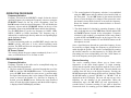
SPECIFICATION:
INSTALLATION:
Location/Connection
GENERAL
Frequency Range
Emission Types
Frequency Control
Frequency Tolerance
Frequency Stability
Temperature Range
Antenna Impedance
Antenna Connectors
28.0000 – 29.6999 MHz
CW, FM, AM, USB, LSB
Phase-Lock-Loop Synthesizer
0.005%
0.003%
-30OC to +55OC
50 Ohms
Standard SO-239 Type
Meter Function
Meter #1: RF Output Power / Antenna SWR.
Meter #2: Received Signal Strength / MOD%
AC Input Voltage
AC 120V , 60 Hz
TRANSMITTER
RF Power Output
Antenna Connectors
AM Modulation
Clarifier Range
Spurious Emissions
Carrier Suppression
The transceiver should be placed in a convenient operating location
close to an AC power outlet and the antenna lead in cable(s).
The transceiver is powered with the AC power cord set. Proceed as
follows to complete all necessary connections to the transceiver.
1. Your transceiver has standard antenna connectors of type SO-239
both located on rear panel; for easy connection to standard PL259 coax plugs. If the coax antenna cable must be made longer,
use coax cable with impedance of 50 ohms and use only enough
cable to suit your needs. This will insure a proper impedance
25W: USB, LSB. 10W: AM, FM, CW
UHF Type, 50 Ohms
Up to 100%
±1 KHz
-60dB
-60dB
RECEIVER
Sensitivity for 10dB S/N
Sensitivity for 20dB S/N
Sensitivity for 10dB S/N
Adjacent Channel Rejection
Image Rejection Ratio
AM: 0.5uV
FM : 0.25uV
USB/LSB: 0.3uV
-60dB
-50dB
AGC Figure of Merit
SSB//AM: 80 dB for 50mV
for 10 dB Change in Audio Output
Audio Output Power @ 10%
2.5W
THD
match and maximum power transfer from the transmitter to the
antenna.
2. AC Power Operation: Use 120 volts AC.
Noise Interference
There are several kinds of noise interference you may encounter in
fixed operation. Some of these noise sources are; fluorescent buzz,
nearby commercial broadcast, electrical appliance, lawnmower, and
electrical storms, etc. Commercial products are available to reduce
interference from these sources. Consult your dealer or professional
amateur radio supply shops.
(SPECIFICATIONS SUBJECT TO CHANGE WITHOUT NOTICE.)
-2-
-3-
Antennas
Antennas
are
Public address
purchased
separately
and
include
installation
An external 8 ohms, 3-Watt speaker must be connected to the PA
instructions. Numerous type of antennas are available that range from
jack located on the rear panel when the transceiver is used as a public
emphasis on easy of installation to emphasis on performance. Often
address system. The speaker should be directed away from the
the difference in performance between many of the antenna is
microphone to prevent acoustic feedback. Physical separation or
modest.
isolation of the microphone and speaker is important when operating
1. Vertical Ground Plane Antennas:
the PA at high output levels.
These are omni-directional antennas that provide optimum
performance for contacting other fixed stations using vertical type
antenna in addition to all mobile stations. For medium to long
range communications work.
2. Directional Beam Antennas:
Highly efficient and directional antennas generally intended for
fixed-to-fixed very long-range communications.
Remote Speaker
The external speaker jack (EXT. SP.) on the rear panel is used for
remote receiver monitoring. The external speaker should have 8
ohms impedance and be able to handle at least 3 watts. When the
external speaker is plugged in, the internal speaker is disconnected.
Note: The PHONE jack on the front panel overrides both external
and internal speakers. When the plug from a headphone is plugged
to the PHONE jack, both internal and external speakers are silenced
simultaneously.
-4-
-5-
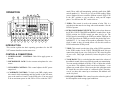
mark.) Then, while still transmitting, push the small white SWR
switch (number 11). This will give you an SWR reading. When
you are finished, be sure to turn the calibrate control. Fully CCW
to the “RF” position so you are able to read your RF output
power. You will hear the “RF” switch click on.
OPERATION:
26
34
23
24
25
28
27
32
30
33
31
29
5. ECHO: This control is used to the amount of echo. This is a
switched pot that must be on along with switch number 6 for the
ECHO to operate.
2527
SWR
RX / TX
0
1
2
0
2
T
SE
3
4
6
8 10 12
1
22
10
M O
D U L AT I O N
20 30
3
5
WATTS
POWER
ON
100 9
R
70 80 90
dBOVE
7 9
60
0 +
+20 +4
SIGNAL
RF POWER
ECHO
OFF
MIN
OFF
MICROPHONE
40 50 60
CALIBRATE
TIME
MAX
MIN
TONE
VOICE
ROBOT
NB/ANL
R.BEEP
SPLIT
PRG
MAN
SHF
DIM
SWR
SCAN
MEM
ENT
LOCK
MAX
TALK BACK
MIC
CHANNEL
RF
CLARIFIER
SQUELCH
VOLUME
R2
ECHO
MODE
AM
R3
USB
LSB
FM
PHONE
CW
PA
R4
OFF
RF
2
1
4
3
6
5
8
7
10
9
12
11
14
13
16
15
18
17
20
19
22
21
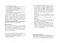
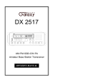
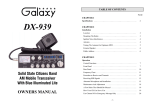
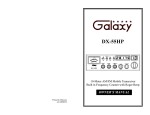
INTRODUCTION
This section explains the basic operating procedures for the DX
2527 amateur band base station transceiver.
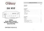
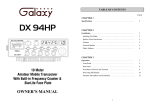
CONTROL & CONNECTIONS:
1. POWER ON/OFF
the unit.
CONTROL: Push ON to apply power to
2. MICROPHONE JACK: Used to connect microphone for voice
source.
3. RF POWER CONTROL: This control adjusts the RF power
output level.
4. CALIBRATE CONTROL: To check your SWR, simply rotate
this control while transmitting until the needle on the left meter
goes to the small red “notch” on the SWR scale. (You may need
to be at maximum power in AM, FM or CW to reach the “SET”
-6-
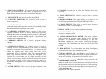
6. ECHO/VOICE/ROBOT SWITCH: This switch selects between
the ECHO, VOICE CHANGER and ROBOT sound effects. In the
ECHO position, the ECHO control pot must also be on. The
ECHO sound is controlled by the ECHO pot and the TIME pot. In
the VOICE position, the TIME pot controls the pitch of the voice.
In ROBOT 1, 2, 3 or 4 none of the sound are adjustable. They are
fixed. In order to have all sound effects off, turn this switch to
ECHO and turn the ECHO pot off.
7. TIME: This control sets the time delay of the ECHO repetitions
in the ECHO modes. In the VOICE CHANGER mode, this pot
controls the pitch of your voice. Fully left (CCW) raises the pitch
of your voice. Fully right (clockwise) lowers the pitch of your
voice.
8. TALK BACK: This is a switched pot that controls the volume of
the talkback sound. It does not affect the sound your transmitting.
You can turn the talkback off (Fully CCW) or adjust the volume
as you desire. This talkback circuit can be used anytime – even
without any sound effects. Please note that this particular main
PC board does not allow much of a talkback signal. Therefore,
even if you have this control up to maximum, the talkback will
not be very loud.
9. RF GAIN CONTROL: This control is used to reduce the gain of
the RF amplifier under strong signal conditions.
-7-
10. MIC GAIN CONTROL: This control adjusts the microphone
gain in the transmit mode. This feature is designed for use in a
high-ambient noise environment or to maximize talk power.
18 VOLUME: Permits you to adjust the listening level when
receiving.
11. SWR SWITCH: This switch is used to check SWR.
19. LOCK SWITCH: This switch is used to lock a selected
frequency.
12. CHANNEL SELECTOR: This control is used to select a
desired frequency.
20. MODE CONTROL: This control allows you to select one of
six following operating modes FM/AM/LSB/USB/CW/PA.
13. SCAN SWITCH: This switch is used to scan frequencies in
each band segment. The operation section of this manual provides
detailed information on using the scan control.
21.• DOWN SWITCH: This switch is used to move frequency
downward to select a desired frequency.
14. CLARIFIER CONTROL: Allows variation of the receiver
operating frequency above and below the selected frequency.
Although this control is intended primarily to tune in SSB signal,
it may be used to optimize AM/FM signals as described in the
operating procedure paragraph.
15. MEMORY SWITCH: This is used to program memory
channels.
16. SQUELCH CONTROL: This control is used to control or
eliminate receiver background noise in the absence of incoming
signal. For maximum receiver sensitivity, it is desired that the
control be adjusted only to the point where the receiver
background noise is eliminated. Turn fully counterclockwise,
then slowly clockwise until the receiver noise disappears. Any
signal to be received must now be slightly stronger than the
average received noise. Further clockwise rotation will increase
the threshold level that a signal must overcome in order to be
heard. Only strong signal will be heard at a maximum clockwise
setting.
17. ENTER SWITCH: This is used to program frequencies into
memory.
-8-
22. PHONE JACK: Used to connect earphone to listening.
23. RF/SWR METER: This meter operates during transmit only. It
reads power output or SWR.
24. SIGNAL/MODULATION METER: This meter indicates
signal strength of incoming signals during receive and your
percentage of modulation when transmitting in the AM.
Modulation readings are most accurate when using maximum
output power. The modulation meter does not work at all in FM
or SSB.
25. DIM SWITCH: This switch adjusts the display backlighting
in four different steps to best match environment.
26. NB/ANL SWITCH: The noise Blanker is very effective in
eliminating repetitive impulse noise such as ignition interference.
In the ANL position, the automatic noise limiter is active.
27. ROGER BEEP SWITCH: When this switch is placed in the
ROGER BEEP position, the radio automatically transmits an
audio tone at the end of your transmission so that people who are
having trouble hearing you will know that you are done speaking.
As a courtesy to others, use the Roger Beep only when necessary.
28. SPLIT SWITCH: This switch enables you to split operating
frequency for FM repeater operation.
-9-
29. PROGRAM SWITCH: This switch is used to program
operating or scanning frequency into memory.
30. FREQUENCY COUNTER: The frequency counter indicates
the frequency of operation.
31. MANUAL SWITCH: This is used to return to the manual
mode.
32. SHIFT SWITCH: This is used to select 100Hz, 1KHz, 10KHz,
100KHz or 1MHz frequency steps.
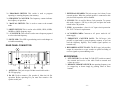
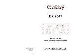
3. EXTERNAL SPEAKER: This jack accepts 4 to 8 ohms, 5-watt
external speaker. When the external speaker is connected to this
jack, the built-in speaker will be disabled.
4. CW KEY: This is used for Morse Code operation. To operate
this mode, connect a CW key to this jack and place the mode
switch in the CW position.
5. FUSE: Accommodates a fuse for AC input circuit protection.
Use 125V/7A fuse for replacement.
22. •UP SWITCH: This switch is used to move frequency upward
to select a desired frequency.
6. AC POWER CORD: Connects to AC power outlet for AC
mains supply.
23. RX/TX LED: This LED is green during receive and changes to
red while transmitting.
7. FREQUENCY COUNTER JACK: The RCA-type jack
provides a signal used by some frequency counters so you can
read the frequency digitally. This readout signal operates on
transmit only.
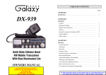
REAR PANEL CONNECTOR:
7
8. RECODDING OUTPUT JACK: The RCA-type jack provides
output for connection to a tape recorder to permit recording of
receiver signals or you modulating voice.
8
MICROPHONE:
1
2
3
4
5
6
1. PTT SWITCH: Use the Push-To-Talk (PTT) switch to control
the transmit and receive of the radio. Push to transmit and
release to receive.
2. REMOTE UP/DOWN SWITCH: An operating frequency can
be stepped up or down simply by pushing either of these
buttons.
1. ANTENNA: This jack accepts 50 Ohm coaxial cable with a
PL-259 type plug.
2. PA SP: Used to connect a PA speaker (8 Ohm 4w) for PA
operation. Before operating PA you must first connect a PA
speaker to this jack.
- 10 -
- 11 -
OPERATION PROCEDURE
Frequency Selection
Frequency selection for the DX 2527 is simple. Select the desired
operating frequency by rotating the Frequency selector or using the
UP/DOWN buttons on the top of the microphone. Press the
LOCK button to lock the selected frequency. This will disable the
frequency selector and the UP/DOWN buttons on the top of the
microphone. Repressing the LOCK button unlocks the frequency.
Use the SHF button to set the step frequency in 100Hz, 1KHz,
10KHz, 100KHz or 1MHz increments. The frequency step is
indicated by a small triangle directly under the corresponding digit
on the frequency display.
Mode Selection
To select an operating mode on your DX 2527, simply rotate the
MODE selector, and place it in the desired operating mode
position. The PTT switch on the microphone controls the transmit
and receive of your radio.
RF Power Control
This control adjusts the power output continuously from 1 to 25
watts, on SSB and from 0.25 to 10 watts on AM.
PROGRAMMING
Frequency Selection
Frequency selection in the radio can be accomplished using any
three of the following methods:
1. The first method of frequency selection I through the use of the
SHF key and the UP and DOWN arrows. To accomplish this,
press the SHF button until the cursor arrow is position under
the digit of the frequency that is to be changed. Then use the UP
arrow to increase the number. If a decrease in frequency is
desired, press the DOWN arrow. Perform the steps described
above for each digit of the frequency until the desired frequency
is displayed in the LCD display windows.
- 12 -
2. The second method of frequency selection is accomplished
using the SHF button and the channel select knob located on
the front panel. Use the SHF button in the manner described
above to select the digit to be changed. Then proceed to rotate
the channel selector knob clockwise to increase the frequency.
Rotate the channel select knob counterclockwise to decrease
the frequency.
3. The third method of selecting he operating frequency of the
radio is through the use of the SHF button and the channel UP
and DOWN buttons located on the microphone. Frequency
selection by this method is accomplished in the same manner
as with the UP and DOWN arrows on the keypad. The only
difference is that the channels UP and DOWN buttons on the
microphone are used.
Once a signal has been detected on a particular frequency, It may
be necessary to slightly change the frequency to provide the best
audio through the speaker. This can be accomplished by rotating
the clarifier control to vary the frequency by ±0.5 KHz. After this
fine-tuning has been accomplished, press the LOCK button to
lock in the frequency at the point of best reception.
Receive Scanning
The receive scanning feature allows you to locate active
frequencies in the entire band segment. To begin scanning,
slowly turn the squelch control clockwise until the receiver noise
disappears. Next, press the SCAN button. The unit should start
scanning from the lower to the higher frequency. Pressing the
SCAN button again will change the direction of scanning. When
the SCAN button is pressed "SCAN+" or "SCAN-" will be
displayed on the LCD display. The scan will stop on any active
frequency for the duration of the transmission. When the
transmission stops, the DX 2527 will wait approximately 2
seconds before it resumes scanning. If you want to deactivate
Scan mode while it's scanning, press the MAN (manual) button
- 13 -
or turn the Squelch control counterclockwise until you hear the
receiver noise. The MAN button will disable the Scan function.
(See Frequency Scanning for more information.)
Split Function
This function enables you to split the transmit and receive
frequencies for FM repeater operation. To split frequencies, press
the MAN button and the SPLIT button to select + split
frequency. If you want - split frequency, press the SPLIT button
again. If + split is selected, the transmit frequency will be higher
than the receiver frequency. If - split is selected, it will be lower
than the receive frequency. (See Offset Frequency Operation for
more information.)
Memory Function
The DX 2527 can store up to 10 channels (from 0 to 9). To
program a frequency into memory, follow the procedure
described below:
1. Press the MAN button.
2. Press the PRG button.
3. Press the MEM button. ("MEMORY" and "0" should appear
on the left-hand side of the LCD display. Pressing the MEM
button will advance the memory number from "0" to "9".)
4. Select the desired frequency you wish to store in memory.
5. Press the ENT button.
6. Repeat the procedure to program other memory channels.
Memory Channel Scanning
You can scan and select any of the 10-programmed frequencies
by following the procedure described below:
1. Press MAN button.
- 14 -
2. Press the MEM button.
3. Slowly turn the Squelch knob clockwise until the receiver
noise disappears.
4. Press the SCAN button. The unit will scan from lower to
higher frequencies. Press again, the unit will scan from higher
to lower frequencies.
5. To stop scanning a certain channel, press the MAN button, or
turn the Squelch knob counterclockwise until you hear the
receiver noise.
Metering
The meter built into your DX 2527 on the left hand side of the
LCD display provides the following information:
1. RF/SWR METER: This meter operates during transmit
only. It indicators power output or SWR.
2. S/MOD METER: This meter indicates incoming signal
strength during receive and your modulation percentage while
transmitting on AM. Modulation indications are most accurate
at maximum AM output. There is no reading while transmitting
on FM or SSB.
Frequency Scanning
Frequency scanning can be achieved using one of two methods:
the first method involves scanning of pre-programmed memory
channels; the second method will permits the user to scan all
frequencies between a pre-set upper and lower scan limit. Both
methods of frequency scanning follow.
All-Frequency Scanning
To allow all Frequency scanning, one must first program the
upper and lower scanning limits. The scan limits are simply the
highest and lowest frequencies that will be scanned. To program
these limits, perform the following steps:
- 15 -
1. Press the PRG (Program) button.
2. Press the SCAN button. ("PRG SCAN+" should appear in
the lower right corner of the display window.)
3. Using the SHF button and UP and DOWN arrows, select
the upper scan limit, then press ENT.
4. Press the SCAN button again. ("SCAN-" should appear in
the display window.)
5. Using the SHF button and UP and DOWN arrows, select
the lower scan limit, then press ENT.
The upper and lower scan limits have now been programmed.
To activate the scan feature, return the radio to manual
operation and press the SCAN button. If the display shows
"SCAN+", the radio will scan from the lower limit to the
upper limit. If "SCAN-" is displayed, the unit will scan from
the upper limit to the lower limit. To change from "SCAN+"
to "SCAN-" or vice versa, press SCAN.
NOTE: When programmed, the upper and lower scan limits will also act
the upper and lower operating limits of the radio. The radio cannot now
be programmed to operate above or below the scan limits.
Memory Scanning
The DX 2527 has 10 non-volatile (i.e., memory resident)
memory locations that can be programmed with any available
frequency within the operating band of the radio. The scan
function of the unit can be programmed to scan these memory
channels. The radio will then scan only those memory channels
that have been pre-programmed.
The first step in utilizing the memory scan function is to
program the desired frequency into the radio memory. This can
be accomplished by performing the following steps:
1. With the radio operating in the manual mode, press the
PRG (Program) button.
- 16 -
2. Press the MEM button. "PRG" should be display in the
lower right-hand corner of the LCD display window. In the
upper left portion of the display, "MEM" should be
displayed. Directly below MEM, a number between 0 and
9 will be displayed. This number represents the memory
location currently being displayed. Pressing the MEM key
will increase the memory counter to the next memory
location and the contents of that memory location will be
displayed.
3. Using the SHF button and UP and DOWN arrows, enter
the frequency to be stored in the memory location
displayed. After the desired frequency has been entered,
press ENT.
4. Repeat steps 2 and 3 for all of the memory locations to be
programmed.
5. After the desired memory locations have been programmed
with frequencies, return the unit to the manual mode of
operation by pressing the MAN button.
6. To initiate memory scanning, press MEM and then press
SCAN. As previously discussed, the display will show
"SCAN+" or "SCAN-" to indicate whether the radio is
scanning from the lowest to the highest memory location or
vice versa. To return the radio to normal (non-scanning)
operation, press the MAN button.
Offset Frequency Operation
The DX 2527 has an offset or split frequency feature that will
permits the radio to be operated in a half-duplex mode. This
will allows the user to talk on FM repeaters operating in the 10
meter band. This split frequency function offsets the
- 17 -
transmitter frequency either above or below the receive
frequency by a user programmable amount. In the following
example, programming of a 100 KHz offset will be described.
Before attempting to program the offset frequency, ensure that
the radio is operating in the manual mode by pressing the
MAN button.
1. Press the PRG (Program) button.
2. Press the SPLIT button. The LCD display window will
display "00000" with "PRG" and "SPLIT" being
displayed in the lower left-hand corner.
3. Using the SHF button and the UP and DOWN arrows as
described earlier, program the display to read "01000".
4. Press ENT. A 100 KHz offset has now been programmed
into the radio.
5. Return the radio to manual operation by pressing the MAN
button.
6. Using the SHF button and the UP and DOWN arrows as
described previously, set the radio for the desired receive
frequency.
7. Press SPLIT. In the lower right corner of the display,
either "SPLIT+" or "SPLIT-" will be displayed. If
"SPLIT+" is displayed, the transmitter will be offset 100
KHz above the receive frequency when keyed. If "SPLIT" is displayed, the transmitter will be offset 100 KHz
below the receive frequency.
•
“Limited” means that we will repair problems caused by factory defects or normal use
at no charge.
•
Before returning a radio to us for warranty service, please call our Service Department
for a Repair Authorization Number (RAN). This RAN must be written below your
return address on the outside of the shipping box. Boxes, which arrive without a RAN,
will be refused, and the shipping company will return the unopened box to you. Be sure
to have a pen and paper ready along with the serial number of your radio before calling.
We will give you the RAN and our shipping address over the phone. The telephone
number of the Service Department is (760) 480-8800, and we suggest calling between
10:00 AM and 4:00 PM Pacific Time.
•
Please include a note with a detailed description of the symptoms. This is important
because it will help the technician who works on your radio to locate your problem.
Intermittent problems are easily overlooked, so be sure to give as much detail as
possible in your note. Also, please include your telephone number in case our
technicians have any additional questions.
•
Do not send your power cord or microphone unless we ask for these items during our
telephone conversation.
•
You are responsible for getting the radio safely to us. (We suggest using United Parcel
Service.) You must pay to ship the radio to us, and we will pay to ship the radio back to
you. Since we use UPS and they do not ship to Post Offices boxes, please provide us
with a street address for the return of your radio.
•
We will repair and return your radio as soon as we can. We appreciate your choosing a
Galaxy radio and we want you to be on the air as much as possible!
Be sure to visit our web site at
www.GalaxyRadios.com
NOTE: When the transmitter is keyed, the frequency display will change
to show the frequency being transmitted.
PRINTED IN TAIWAN
ATTURO010J
WARRANTY
This radio is covered by a two year
limited parts and labor warranty.
- 18 -
- 19 -