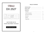
1
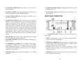
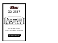
DX 2517
2517
RX / TX
SWR
1
0
2
2
SE
3
4
6
T
81012
1
22
WATTS
POWER
ON
SWR
0 10 MODULAT I ON
2030
405060708090100R9
dBOVE
3 5
0+6
7 9 +20+4
0
PA FM AM USB LSB CW
SIGNAL
NB / ANL R.BEEP +10KHz
CHANNEL
NF
MODE
FM
PA
OFF
CAL
MICROPHONE
CALIBRATE
OFF
OFF
T.B.
DIM
NORMAL
OFF
MIC
RF
TIME
CW
BAND
ECHO
B
A
OFF
RF POWER
AM USB
LSB
C
D
SQUELCH
VOLUME
FINE
COARSE PHONE
E
F
OFF
AM·FM·SSB·CW·PA
Amateur Base Station Transceiver
OWNER’S MANUAL
TABLE OF CONTENTS
SPECIFICATION :
GENERAL
SPECIFICATIONS .............................................................
2
INSTALLATION ................................................................
3
OPERATION
Introduction ....................................................................
6
Control & Connections ……………………………………
6
Rear Panel Connectors …………………………………...
10
Microphone …………………………………………………
11
Operation …………………………………………………...
11
Frequency Range
Emission Types
Frequency Control
Frequency Tolerance
Frequency Stability
Temperature Range
Antenna Impedance
Antenna Connectors
Meter Function
AC Input Voltage
28.765 – 29.205 MHz
CW, FM, AM, USB, LSB
Phase-Lock-Loop Synthesizer
0.005%
0.003%
-30OC to +55OC
50 Ohms
Standard SO-239 Type
Meter #1 : RF Output Power / Antenna SWR.
Meter #2 : Received Signal Strength /
MOD%
AC 120V , 60 Hz
TRANSMITTER
RF Power Output
Antenna Connectors
AM Modulation
Clarifier Range
Spurious Emissions
Carrier Suppression
25W : USB, LSB. 10W : AM, FM, CW
UHF Type, 50 Ohms
Up to 100%
±5KHz XMT & REC; ±1.5KHz REC only
-60dB
-60dB
RECEIVER
Sensitivity for 10dB S/N
Sensitivity for 20dB S/N
Sensitivity for 10dB S/N
Adjacent Channel Rejection
Image Rejection Ratio
AM : 0.5uV
FM : 0.25uV
USB/LSB : 0.3uV
-60dB
-50dB
AGC Figure of Merit
SSB/AM : 80 dB for 50mV
for 10 dB Change in Audio Output
Audio Output Power @ 10%
2.5W
THD
(SPECIFICATIONS SUBJECT TO CHANGE WITHOUT NOTICE.)
-1-
-2-
INSTALLATION:
Antennas
Location/Connection
Antennas
are
purchased
separately
and
include
installation
The transceiver should be placed in a convenient operating location
instructions. Numerous type of antennas are available that range from
close to an AC power outlet and the antenna lead in cable(s).
emphasis on easy of installation to emphasis on performance. Often
The transceiver is powered with the AC power cord set. Proceed as
the difference in performance between many of the antenna is
follows to complete all necessary connections to the transceiver.
modest.
1. Vertical Ground Plane Antennas:
1. Your transceiver has a standard SO-239 connector on the rear
These are omni-directional antennas that provide optimum
panel for easy connection to standard PL-259 coax plug. If the
performance for contacting other fixed stations using vertical type
coax antenna cable must be made longer, use coax cable with
antenna in addition to all mobile stations. For medium long range
impedance of 50 ohms and use only enough cable to suit your
communications work.
needs. This will insure a proper impedance match and maximum
2. Directional Beam Antennas:
Highly efficient and directional antennas generally intended for
power transfer from the transmitter to the antenna.
fixed-to-fixed very long range communications.
2. AC Power Operation: Use 120 volts AC.
Remote Speaker
Noise Interference
The external speaker jack (EXT. SP.) on the rear panel is used for
There are several kinds of noise interference you may encounter in
remote receiver monitoring. The external speaker should have 8
base station operation. Some of these noise sources are; fluorescent
ohms impedance and be able to handle at least 3 watts. When the
buzz,
external speaker is plugged in, the internal speaker is disconnected.
nearby
commercial
broadcast,
electrical
appliance,
lawnmower, and electrical storms, etc. Commercial products are
Note: The PHONE jack on the front panel overrides both external
available to reduce interference from these sources. Consult your
and internal speakers. When the plug from a headphone is plugged
dealer or professional amateur radio supply shops.
to the PHONE jack, both internal and external speakers are silenced
simultaneously.
-3-
-4-
OPERATION:
Public address
An external 8 ohms, 3 Watt speaker must be connected to the PA jack
located on the rear panel when the transceiver is used as a public
1
3
27 2
4
5
6
7
8
9
10
26
address system. The speaker should be directed away from the
microphone to prevent acoustic feedback. Physical separation or
2517
isolation of the microphone and speaker is important when operating
RX / TX
the PA at high output levels.
POWER
ON
SWR
1
0
2
2
T
SE
3
4
6
81012
1
22
WATTS
SWR
0 10 MODULAT I O N
2030
0
40506070809010ER
9
dBOV
0
3 5
0+6
7 9 +20+4
PA
FM AM USB LSB CW
SIGNAL
NB / ANL R.BEEP +10KHz
CHANNEL
NF
MODE
FM
RF POWER
AM USB
LSB
CW
PA
OFF
CAL
MICROPHONE
CALIBRATE
OFF
OFF
T.B.
NORMAL
OFF
MIC
RF
DIM
TIME
BAND
ECHO
B
C
D
OFF
11
12
VOLUME
21
23
FINE
COARSE PHONE
F
OFF
14
13
SQUELCH
E
A
16
17
18
15
20
19
24
25
22
INTRODUCTION
This section explains the basic operating procedures for the DX
2517 amateur base station transceiver.
CONTROL & CONNECTIONS:
1. POWER ON/OFF
the unit.
CONTROL: Push ON to apply power to
2. RF/SWR METER: This meter operates during transmit only. It
reads power output or SWR.
3. SWR/CAL SWITCH: This switch is used with the
“CALIBRATE” pot (No.12) to measure your SWR. Simply put
this switch in the “CAL” position. Then, transmit in AM, FM or
CW while adjusting the “CALBRATE” pot until the needle on the
left meter goes to the small red “Notch” on the SWR scale (You
may need to be at maximum power to reach the “SET” mark).
Now, while still transmitting, put this switch up to the “SWR”
-5-
-6-
position. This will give you an SWR reading. When you are
finished, be sure to turn the “CALIBRATE” pot fully CCW to the
“RF” position so you are able to read your output power. You will
hear the “RF” switch click on.
4. NB/ANL SWITCH: This switch controls the Noise Blanker and
Automatic Noise Limiter simultaneously. They are turned on and
off together. The noise Blanker is very effective for eliminating
repetitive impulse noise such as ignition interference. The
Automatic Noise Limiter reduces strong atmospheric or manmade interference.
5. ROGER BEEP SWITCH: When this switch is placed in the
ROGER BEEP position, the radio automatically transmits an
audio tone at the end of your transmission so that people who are
having trouble hearing you will know that you are done speaking.
As a courtesy to others, use the Roger Beep only when necessary.
6. NOISE FILTER: This filter de-emphasizes audio high frequency
response in order to increase the signal-to-noise ratio of weak
signals. While you will notice a dramatic reduction in the
“rushing” sound when this filter is activated., it does not have
much effect on the signal-to-noise ratio of strong signals.
7. +10KHz SWITCH: This switch adds 10KHz to the frequency
being used. Example, if frequency counter display 28.765, flip the
switch and the display will read 28.775MHz.
8. SIGNAL/MODULATION METER: This meter indicates signal
strength of incoming signals during receive and your percentage
of modulation when transmitting in the AM. Modulation readings
are most accurate when using maximum output power. The
modulation meter does not work at all in FM or SSB.
-7-
9. CHHANEL DISPLAY: The channel display indicates the
current selected channel.
10. FREQUENCY COUNTER: The frequency counter indicates
the frequency of operation.
11. MICROPHONE JACK: Used to connect microphone for voice
source.
12. CALIBRATE CONTROL: In the “RF” position, the left meter
reads power output in watts. When rotated clockwise, it is used in
conjunction with the “SEW/CAL” switch (No.3).
13. DIM CONTROL: Controls the brightness of the meter lamps
and display digits.
14. TALK BACK: This is a switched pot that controls the volume
of the talkback sound. It does not affect the sound your
transmitting. You can turn the talkback off (Fully CCW) or adjust
the volume as you desire. This talkback circuit can be used
anytime – even without any sound effects.
15. RF GAIN CONTROL: This control is used to reduce the gain
of the RF amplifier under strong signal conditions.
16. MIC GAIN CONTROL: This control adjusts the microphone
gain in the transmit mode. This feature is designed for use in a
high-ambient noise environment or to maximize talk power.
17. TIME/ECHO CONTROL: This “TIME” control pot turns the
ECHO on and off and is used to set the time delay of the ECHO
repetitions. The ECHO control sets the intensity of the ECHO
effect.
-8-
18. CHANNEL SELECTOR: This control is used to select a
desired frequency.
26. MODE LED INDICATORS: The lighted LED indicates which
mode the radio is in.
19. MODE CONTROL: This control allows you to select one of
six operating modes: PA/FM/AM/USB/ LSB/CW
27. RX/TX LED: Lights green during receive and changes to red
during transmit.
20. BAND SELECT SWITCH: This switch is allow the user to
select the desired band.
REAR PANEL CONNECTOR:
21. SQUELCH CONTROL: This control is used to control or
eliminate receiver background noise in the absence of incoming
signal. For maximum receiver sensitivity, it is desired that the
control be adjusted only to the point where the receiver
background noise is eliminated. Turn fully counterclockwise, then
slowly clockwise until the receiver noise disappears. Any signal
to be received must now be slightly stronger than the average
received noise. Further clockwise rotation will increase the
threshold level which a signal must overcome in order to be
heard. Only strong signal will be heard at a maximum clockwise
setting.
22. RF POWER: This control is used to adjust the RF power output
level you want in AM or FM transmission.
23 VOLUME CONTROL: Permits you to adjust the listening level
when receiving.
7
8
1
1.
2
3
4
5
6
AC POWER CORD : Connects to AC power outlet for AC
mains supply.
2. FUSE : Accommodates a fuse for AC input circuit protection.
Use 125V/7A fuse for replacement.
24. COARSE/FINE CONTROL: The “COARSE” control adjusts
the frequency ±5.0KHz in receive and transmit. The “FINE”
control adjusts the frequency ±1.5KHz in receive only. This
comes in handy when tuning in someone who is “OFF” frequency
compared to everyone else.
3. EXTERNAL SPEAKER: This jack accepts 4 to 8 ohms, 5 watt
external speaker. When the external speaker is connect to this
jack, the built-in speaker will be disabled.
4. PA SP: Used to connect a PA speaker (8 Ohm 4w) for PA
operation. Before operating PA you must first connect a PA
speaker to this jack.
25. PHONE JACK: Accepts a plug from a headset of 4 to 32 Ohm
impedance.
5. ANTENNA: This jack accepts 50 ohm coaxial cable with a type
PL-259 plug to be connected.
-9-
- 10 -
6. REC JACK: The RCA-type (pin) jack provides audio output for
connection to a tape recorder. This can be used to record
incoming signals or your voice when transmitting.
8. FREQUENCY COUNTER JACK: The RCA-type jack
provides a signal used by some frequency counters so you can
read the frequency digitally. This readout signal operates on
transmit only.
4. CW KEY: Use for Morse Code operation. Connect a CW key to
this jack and place the MODE switch in the CW position.
MICROPHONE:
The receiver and transmitter are controlled by the push-to-talk
switch on the microphone. Press the switch and the transmitter is
activated, release switch to receive. To transmit, hold the
microphone about two inches from your mouth and speak clearly
in a normal voice. The radio comes complete with a low impedance
dynamic microphone.
OPERATION PROCEDURE
A. PROCEDURE TO RECEIVE
1. Make sure that the power cord, microphone and antenna are
connected properly.
2. Turn the volume down to about the nine o’clock position.
3. Set the mode switch.
4. Push the power switch on. The meter and display LED’s
should light up unless the dimmer control is set too low.
5. Select the desired frequency.
6. Adjust the receive gain for maximum.
7. Set the squelch as desired.
8. Use the “COARSE/FINE” control as necessary to tune
signals in properly.
- 11 -
B. PROCEDURE TO TRANSMIT
1. Set the MIC gain fully clockwise.
2. Press the push-to-talk switch on the microphone and speak
directly into the microphone.
3. Adjust the MIC gain down if the person you are talking to
says your are too loud.
C. MICROPHONE GAIN CONTROL
A preamplifier circuit is built into the radio to increase the
microphone gain. Experiment with the control for setting that
will best suit your individual use.
Note: When the microphone gain control is set to maximum,
ambient noise may also be picked up by the microphone. In high
noise situations, low microphone gain setting may produce the
best results. The microphone gain control is also used to adjust
PA loudness.
D. PUBLIC ADDRESS OPERATION
To use this feature of the transceiver, a speaker having a voice
coil impedance of 8 to 16 Ohms and power handing capability
of least 3 watts should be connected to the PA SP jack on the
rear panel. Be sure that there is physical separation between the
microphone and the PA speaker itself. If the PA speaker is
located very close the microphone, acoustic feedback will result
when the PA amplifier is operated at high volume (or when PA
is used indoor). Adjustment of PA volume is made with MIC
GAIN control.
E. S.W.R MEASUREMENT
Most antenna are factory tuned, but the antenna efficiency may
be peaked by slightly adjusting the length of antenna using the
SWR meter built into the unit. This adjustment may improve the
antenna standing wave ratio (SWR). The SWR permits you to
determine how well matched the antenna and its cables are to your
transceiver.
- 12 -
1. Set the unit in the receive mode as instructed under the
operating procedure to receive section.
2. Set the mode switch to AM position, the SWR-CAL switch to
the CAL position.
3. Press the push-to-talk switch on the microphone and turn the
calibrate control clockwise (past click) so that the SWR meter
pointer exactly coincides with the set mark on the scale.
Release the push-to-talk switch.
4. Set the SWR-CAL switch to the SWR position and depress
the push-to-talk switch again. The SWR of your antenna is
read directly on the scale.
WARRANTY
This radio has a one year parts and
labor warranty. For warranty service,
please contact your dealer.
BE SURE TO VISIT OUR WEB SITE AT:
www.galaxyradios.com
- 13 -
- 14 -
PRINTED IN TAIWAN
AT0SSB010W
- 15 -