1
Introduction to the Coldfire 5272
J.-M Friedt, S. Guinot, É. Carry
Association Projet Aurore, 16 route de Gray 25030 Besançon
http://projetaurore.assos.univ-fcomte.fr
7 juin 2005
We here aim at a step by step introduction to the use of embedded systems based on uClinux.
The objective is to allow one to get familiar with linux-running embedded systems on a limited
budget. We will first tackle the hardware aspects including the printed circuit board (PCB) to be
developed for running a test circuit. We will then present the development environment and most
interstingly the cross-compiler 1 for generating a Motorola-compatible binary in a computer based
on an Intel processor. Finally we will show how to access hardware peripherals of the processor
and the programming method somewhat unusual on embedded devices.
1
Hardware aspects
The uClinux kernel [1, 2, 3] has been ported to a wide range of microcontrollers and processors.
Its main contribution is to run on systems with no Memory Management Unit (MMU) and hence
to run on relatively simple embedded devices only including a microcontroller and a few additional
necessary peripherals. We impose two requirements in choosing the hardware : price and weight.
The latter requirement is defined by our objective : the final system should fit in a flying object,
hence the necessity for a lightweight, low volume and simple power supply circuitry to be used
with our processor board. Our choice is the Arcturus Networks uCdimm 5272 [4], which answers
our price criteron (275 US dollars including shipment) and most importantly as being the smallest
system we could find for such a computational power (for example a Renesas H8 microcontroller [5]
based board – smaller and cheaper – was eliminated for lack of sufficient memory and processing
power). The hardware we selected includes 4 MB of non-volatile flash memory, 8 MB RAM,
a Motorola Coldfire 5272 processor clocked at 66 MHz and a second 100 Mb/s ethernet port
(additional to the one includeed on the processor).
The uCdimm 5272 is provided with no documentation other than the few web pages available
on the Arcturus web page (mainly the connector pinout and the commands of the proprietary
bootloader provided for hardware initialization). A much more expensive development daughter
board is available but was not within our available budget (uCevolution board). The datasheet
of the embedded processor, Motorola Coldfire 5272 [6], quickly becomes a fundamental reading in
order to understand the capabilities of this system as will be described later.
Getting the Arcturus uCdimm 5272 to run is surprisingly simple : the only requirement is a
3.3 V power supply (which is provided in our case by a LM317 voltage regulator compatible with
a wide input voltage range – 5-37 V – including the slowly decreasing voltage of a battery pack)
properly decoupled to ground by a 440 nF capacitor. The voltage regulator does not even require
a heat sink since the power consumption is so low. The RS232 ports are directly usable : the TTL
to RS232 voltage converters are included on the board. The same is true of the ethernet ports :
the transformers converting the output signals to differential pairs are mounted on the board and
use a large volume over the PCB. The connector is a SODIMM 144 pins as found for connecting
RAM on laptops (bought from Digikey in the US since we were unable to locate such connectors
in France [7]). One must expect though, to compensate for the expensive daughter board sold by
Arcturus, the access to a mandatory SMD-compatible soldering iron and a binocular microscope
for soldering the connector as well as the ability to etch a single-sided PCB with tracks separated
by 0.8 mm.
1 cross-compilation : compiling a binary for a given target architecture (Motorola Coldfire) on a processor of
another architecture (here Intel x86 or SPARC)
1
uCdimm5272
camera1
eth0
ttyS0
regul. 3.3 V
bus : ports A−C
camera2
5−12V
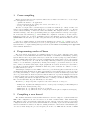
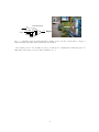
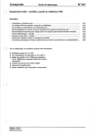
Fig. 1 – Test board including the emulation of a TTL compatible PC parallel port for interfacing the webcam. The board holding the uCdimm (including the voltage regulator, and ethernet
connector and an RS232 connector) is visible to the left while the A, B and C busses are transported to a daughter-board dedicated to the CMOS-TTL levels conversion and multiplexing these
busses to the two webcams.
2
First-time startup
The chances of electrical mishandling are quite reduced thanks to the simple connections. The
first test is to check whether when powered up, the uCdimm 5272 transmits a message. The default
protocol used is to communicate through the first serial port, 9600 bauds and N81. The following
messages, obtained either by cat < /dev/ttyS0 or cu -l /dev/ttyS0 -s 9600, appear upon
power up :
uCbootloader 1.7.7r1
(c) Copyright 2001-2004 Arcturus Networks Inc.
All Rights Reserved.
CACHE on
BOOT FLASH type 00c8 AT49BV32XA @0x10c00000
DP|002000 DP|004000 DP|006000 DP|008000 DP|00a000
DP|00e000 DP|010000 DP|020000 D-|030000 D-|040000
D-|060000 D-|070000 D-|080000 D-|090000 D-|0a0000
D-|0c0000 D-|0d0000 D-|0e0000 D-|0f0000 D-|100000
D-|120000 D-|130000 D-|140000 D-|150000 D-|160000
D-|180000 D-|190000 D-|1a0000 D-|1b0000 D-|1c0000
D-|1e0000 D-|1f0000 D-|200000 D-|210000 D-|220000
D-|240000 D-|250000 D-|260000 D-|270000 D-|280000
D-|2a0000 D-|2b0000 D-|2c0000 D-|2d0000 D-|2e0000
...
D-|400000
DP|00c000
D-|050000
D-|0b0000
D-|110000
D-|170000
D-|1d0000
D-|230000
D-|290000
D-|2f0000
B$
The command “go” then launches the operating system stored in non-volatile flash memory.
The uCdimm 5272 is provided with a functional uClinux system. A classical linux bootsequence
is observed until a login prompt appears : the only account is root with the password uClinux.
Discovering the available tools is straighforward : all executable binaries are located in /bin. We
will see later, section 6, how to use minicom to communicate and transfer new binary images.
Having checked that the communication through the serial port is working, we still have to
test the ethernet connexion. The default IP address of the uCdimm is 192.168.1.200 which is
initialized if, and only if, an ethernet connexion is detected during the boot sequence. The common
network configuration tools ifconfig and route are available to chage these parameters and a
ping command towards the host used as the serial terminal allows us to check that the ethernet
communication is functional. The system is shipped with a telnet daemon (login : root, passwd :
uClinux) waiting for a connexion, as well as mount. The filesystem of the host can thus be exported
by NFS using the following command : mount -o nolock,moutvers=2 IP hote :répertoire
/mnt where the options are necessary for a proper communication between the NFS server provided
in a linux 2.4.22 kernel and the uCdimm.
2
3
Cross-compiling
Having checked that the basic system is functional, we must now learn how to cross-compile
our own application in order to
– optimize the kernel to our application
– add new applications (for exampe web server, text editor, etc ...)
– develop our own applications
We have recompiled the toolchain targetted towards the m68k-elf (i.e. binary for Motorola
68k processors in ELF format which will then be converted to a flat binary format to be directly
executed under uClinux) on Intel-based PCs and SPARC. The simplest method on PCs is to
unarchive an image of the directory including all the precompiled binaries for intel processors (gcc,
ld, as and associated libraries) [8]. Under SPARC the compilation of all these tools is necessary :
binutils (v.2.10), gcc (v.2.95.3), genromfs (v.0.5.1) and STLport (v.4.5.3), with the option
TARGET=m68k-elf, the whole procedure being automated by the script build-uclinux-tools.sh
[9].
Once the toolchain available, we must fetch an uClinux source archive [10], configure it for our
hardware and compile a new kernel (see section 5). Our application to be included in the embedded
system will also be compiled during this step as described in Documentation/Adding-User-Apps-HOTO
in the uClinux distribution.
4
Programming under uClinux
The development environment on a uClinux system is closer to that commonly found on microcontrollers or under MS-DOS than that found usually on a multiuser, multitasking operating
system. The fact that our program can freely access the whole memory range is possible thanks to
the lack of MMU which thus cannot generate a (segmentation fault) when our process attempts
an access to a memory zone out of its allocated range. This major difference provides us with the
ability to access hardware peripherals by writing and reading to pre-defined memory locations
since on Motorola architectures input/output peripherals are reached as memory accesses. Hence
we will use somewhat unusual commands in which the pointer addresses are defined to reach a
predefined memory location.
A first simple example is to have LEDs connected to ports A and C (pins 53-60 and 71-74 of the
uCdimm 5272) blink. Reading the Coldfire 5272 datasheet teaches us that these ports are accessed
by reading and writing to a base register, MBAR, incremented by 0x86 and 0x96 respectively. The
choice of ports A and C is dictated by the fact that the functions of port B are multiplexed between
a digital general purpose input-output (GPIO) port and the first serial port (ttyS0) which want
to keep running. We will see though later that due to naming conventions differences between
Motorola and Arcturus, all ports will finally become usable.
We will see [6, chapter 17] that 3 registers control the behaviour of each port :
– PiCNT (i=A, B) defines the mulitplexed mode of each port (for example port B is multiplexed
with the first ethernet/serial ports)
– PiDDR (i=A, B, C) defines the direction of each pin
– PiDAT (i=A, B, C) defines the level of each pin (read if the pin is configured as an input)
5
Compiling a new kernel
The uClinux distribution includes linux kernels 2.4 and 2.6 adapted to systems which lack
MMU. The configuration is done as would be done with a classical linux : make menuconfig.
The difference then comes with the menu that appears : instead of directly getting to the kernel
configuration menu, the user selects which hardware he is working on (in our case Arcturus 5272)
and selects whether he wants to modify the default parameters of the kernel for this hardware (in
our case we must change the processor frequency from 48 to 66 MHz and the amount of RAM
3
from 2 to 4 MB) and/or the applications compiled in the disc image to be loaded to RAM. We
always use the compact C library uClibc. AFter leaving this first menu, the following menus (kernel
configuration and utilities) appear. The compilation is then completed by running make dep and
make which end up by putting in the images directory an image of the disc image.bin ready to
be transferred to the RAM of the embedded device, and in the romfs directory the individual
files included in this image. By mounting via NFS this latter directory, one can execute these new
programs without having to transfer the whole image to RAM through the RS232 link (rx from
the bootloader), a lengthy operation detailed in the next paragraph. Notice that the kernel always
executes from RAM due to excessive memory access times to the other kinds of memories : even
a kernel to be stored in flash memory must be defined (in the Processor type and features
menu of the kernel configuration) with Kernel executes from RAM.
6
Transferring an image of the filesystem
We have seen that cat or cu can be used for monitoring the behaviour of the uCdimm. A more
complete tool is minicom, which however requires a few initial configurations to be usable :
1. lancer launch the configuration pannel of minicom by “CTRL-A O”
2. Serial port setup → Serial Device → /dev/ttyS0
3. Serial port setup → Bps/Par/Bits → 9600 8N1
4. Serial port setup → Hardware Flow Control → No
5. Serial port setup → Software Flow Control → No
and check that under “File transfer protocols” we have “xmodem /usr/bin/sx -vv”
There is no use attempting an image transfer at 115200 bauds : while all our transfers succeeded
at 57600, they always failed at 115200. Once an image has been transferred, remember to set the
terminal speed back to 9600 bauds before launching the goram command since linux will open
a terminal on the serial port expecting communication at this speed. After observing that the
image stored in RAM behaves as expected, it can be permanently transferred to flash memory by
running the instruction program from the bootloader after the transfer rx. In our case a satisfying
result was obtained after :
– having edited etc/inittab and removing the execution of agetty in order to free the serial
ports (this is done in the vendor/Arcturus/uC5272 directory otherwise this file would be
replaced by the default one during the next kernel compilation)
– having added in etc a file passwd including an entry for root with no password (in the
directory romfs/etc since this file is not replaced during the compilation of a new kernel)
– having added in the user applications fundamental tools such as ls, mkdir and, in order to
activate NFS access, portmap and mount. Notice that for the latter, the default uClibc configuration must be edited to activate RPC (deactivated by default : modify UCLIBC HAS RPC=y)
by editing the file config.uClibc
– having added our own programs (either in the romfs/bin directory following manual compilation, or after having appropriately modified the Makefile as described in section 3).
7
Development of a practical application : image transfers
The practical application we wish to develop in order to be able to transfer images from a
captive balloon are :
1. capture images and eventually compress them
2. replace the ethernet connexion by a wireless connexion
3. transfer images in real time through this netwoek connexion
4
The first point will be achieved by using old black and white Connectix Quickcam webcams
which used to be connected to the PC parallel port. This first part will get us used to programming
ports A, B and C as inputs and outputs, as well as with the electronics aspects of converting CMOS
3.3 V logic levels (uCdimm) to TTL level (5 V, webcam).
The second point is simplified by using a commercial product : an ethernet-wifi converter is
used as wireless communication interface.
The last point is achieved by modifying the program controlling the camera so that it continuously transfers images through the network rather than saves them in files.
7.1
Webcam programming
The communication protocol between the PC parallel port and the Quickcam is not freely
available, but several opensource software (Linux, DOS and 68HC11 [11]) provide the successive
steps needed to configure the camera and grab images.
We observe that 8 bits aree needed for the communication from the uCdimm to the camera
(sending commands through port A), 5 bits from the camera to the uCdimm (reading pixels as
nibbles and handshake through port B) and 2 control signals from the uCdimm to the camera
(port C). We will later use an additional 2 output bits on port B to multiplex the ports and
hence connect simultaneously two cameras. Interfacing the 3.3 V logic to TTL is done by resistors
(pull-up resistors from 3.3 V to TTL and current limiting resistors in series from TTL to 3.3 V 2).
We have observed that all pins, whether as inputs or outputs, require such an interface without
which proper communication with the camera could not be achieved. Port A is thus connected to
the camera via a 74LS245 bus interface while ports B and C are connected throught a 74HCT573
latch (the selection of the components being only defined by their availability, and any other TTLcompatible bus-interfacing chip could be suitable). The advantage of using a 74245 to interface
port A is that we will later be able to use this port in both directions (and hence speed up the
image transfer from the camera to the uCdimm).
The uClinux operating system provides the address of some of the useful registers : the base
address register MBAR is defined in asm/coldfire.h (in a constant called MCF MBAR) while the
hardware configuration registers are defined in asm-m68knommu/m5272sim.h.
uClinux (3.3V)
portB
5, 7
2
5
portC
portA
2
5V
74HCT573
8
+5V
EN# DIR
74LS245
+5V
EN# DIR
74LS245
status control
data
parallel port (5V)
status control
data
parallel port (5V)
Connectix Quickcam B&W
Connectix Quickcam B&W
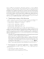
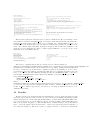
Fig. 2 – Left : interface circuitry between the uCdimm (3.3 V CMOS) and TTL level electronics
compatible with the PC parallel port for connecting a webcam. The TTL components are used as
buffers and eventually for the multiplexing of the ports of the processor between the peripherals.
Port A is used as a bidirectional data-bus (commands from the uCdimm to the camera, pixel
values in the other direction), the 5 least significant bits of port B are used for reading the data
from the camera, port C is used for sending control signals to the camera and finally 2 most
significant bits of port B are used for multiplexing the digital circuits between the two cameras.
Right : example of stereoscopic images obtained with the cameras connected to the uCdimm (6
bits/pixel).
After observing that the adresses of the registers as defined in the uClinux header files indeed
match the values provided in the Motorola Coldfire 5272 datasheet, we were surprised to see that
5
programming ports A to C of the Arcturus hardware seemed not to match the programming rules
given by Motorola. It appeared in fact that the port called B on the uCdimm5272 is in fact the
least significant byte of port C of the Coldfire 5272, port A of the uCdimm is the most significant
byte of port C of the Coldfire 5272, and finally port C of the uCdimm is the most significant
byte of port A of the Coldfire. This surprising result is confirmed by the manipulation of the
port direction registers : the most significant byte of PCDDR must be modified for port B of the
uCdimm to become an output port.
In summary :
– ports are configured as GPIO by
*((volatile unsigned long *)(MCF MBAR + MCFSIM PACNT)) = 0x40000000 ; to use ports
A and B as general purpose input/outputs. There is no use in modifying MCFSIM PBCNT following the naming conventions we just described : ethernet and serial interfaces are always
available.
– PADDR and PCDDR direction registers define whether a port is set for intput or output,
the most significant byte of PC (Coldfire naming convention) setting the direction of port B
(Arcturus Networks naming convention). Hence, to configure ports A and C as outputs and
the 5 least significant bits of port B as inputs with the 3 most significant bits as outputs, we
use
*((volatile unsigned short *)(MCF MBAR + MCFSIM PADDR)) = 0x00ff ;
((volatile unsigned short *)(MCF MBAR + MCFSIM PCDDR)) = 0xe0ff ;
– writing on a port is done in the following way :
*((volatile unsigned char *)(MCF MBAR+MCFSIM PADAT+1))=value ;
to write on port C and
*((volatile unsigned char *)(MCF MBAR+MCFSIM PCDAT+1))=value ;
to write on port A (notice that the names of the port and of the register are inverted due to
the differences in the naming conventions of Arcturus Networks and Motorola).
Reading from port B is done with
value=*((volatile unsigned char*)(MCF MBAR + MCFSIM PCDAT )) ;
Once familiar with these basic concepts (both hardware and software), we just have to implement the communication protocols to grab an image as shown on figure 2 (right). The images are
acquired in a loop and first stored on an NFS-mounted directory for later viewing on a PC with
a graphical interface.
Quickcam control software
The program as described here [12] periodically grabs an image on the uCdimm and transfers
it on the network to clients running on PCs for display and storage. Thus, we have selected to
run a multithreaded server on the uCdimm (using the pthread library optimized for embedded
applications and provided with uClinux) in order to allow multiple remote PCs to connect directly
to the image server, with the aim of disseminating stereoscopic images grabbed by the uCdimm
(on a balloon or an unmanned autonomous vehicle for example) while multiple clients watch
simultaneously the result of these acquisitions. The ethernet connexion was replaced by a wireless
Wifi connexion thanks to a DLink-DWL810+ ethernet to wifi converter, compatible in terms of
supply voltage with an embedded application (5 V voltage regulated by an 7805, 600 mA current).
We have completed the interfacing electronics by doubling all bus management components
(75245 and 74573) so that two cameras could be connected in order to be able to measure the
distance of target objects by means of stereoscopy, the computational power of the Coldfire 5272
being enough for calculating the cross-correlation between a few lines of the acquired images.
Furthermore, we have implemented jpeg image compression either before image transmission (in
order to save bandwidth and hence increase the wifi range), or after reception of the images for a
direct display on a web interface.
6
8
Using the PWM
The Pulse Width Modulation (PWM) generators are useful peripherals for controlling the
speed of DC motors, to make simple digital to analog converters (after low-pass filtering) or, in
our case, for the angular control of servo motors as used in remote controlled models.
Two of the PWMs integrated in the Coldfire 5272 are available to the uCdimm user. Their use
is consistent with their description provided in the 5272 datasheet [6, chapter 18] :
1. PWM i is activated by setting the most significant bit of the control register MCFSIM PWCRi
located at address MBAR+0xc0+4*i (i = 0..2)
2. the repetition rate of the pulses is defined by the division factor set by the least significant
bits of this same register MCFSIM PWCRi
3. the relative width of the pulses is defined by the value stored in MCFSIM PWWDi located at
address MBAR+0xd0+4*i
We thus generate with a division factor of 0x0c pulses on PWM0 every 15.8 ms, with widths
ranging from 1.5 to 2.5 ms when the delays range from 13 to 37, as required for the angular control
of servo motors.
We see in this example the complementarity of the programming methods under uClinux :
simultaneously programming on a high level operating system (for example when accessing the
RS232 ports on the uCdimm exactly as would be done on a PC) and low level programming
as more usually performed on microcontrollers when directly writing to Coldfire 5272 hardware
configuration registers.
9
Interrupts management
Hardware interrupts, which trigger a software event upon a hardware event generated on one of
the pins of the processor, are an unusual case in this presentation since only the kernel can access
these functionalities. We must thus, in order to be able to use these functions of the Coldfire
processor, write a module to be appended to the kernel. There again we will find programming
structures familiar to linux developpers, with methods usual for module programming [13], as well
as hardware specific calls which require an extensive reading of the datasheet of the processor [6,
chapter 7].
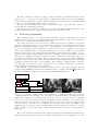
As a first step an additional hardware circuit is needed to trigger a hardware interrupt by a
push-button while avoiding the effect of the contacts bouncing against each other upon switch
closure (debounce) : we add a 7414 Schmitt trigger with a low RC time constant (in order not
to slow down the response time of the circuit) in order to trigger only one (and not several)
interrupts when the switch is closed. The circuit, using a component supplied with 3.3 V (LVC
type), is connected directly to pin 77 of the uCdimm. In case a 3.3 V compatible component is not
readily available, it should be possible to use any TTL-compatible (5 V) component connected to
the hardware interrupt related pin by a resistor (fig. 3).
Similarly to the activation of hardware interrupts on IBM-compatible PCs, the initialization
and acknowledgement sequence after interrupt processing is strongly dependant on the hardware.
In the case of interest here, namely the management of IRQ0# in the Arcturus naming convention
(which is INT2 in the Motorola naming convention), the register with which we must interract is
ICR1 located at address MBAR+0x20. Initializing interrupt i is done by setting INTiIPL to 0x111.
Acknowledging of this interrupt after management of the event is completed by setting to 1 the
bit INTiPI. One must rember during the management servicing (function uc int irqhandler())
to deactivate the interrupt before acknowledging, then to perform the actions associated with this
interrupt, before finally re-activating the interrupt at the end of the service routine. All the other
functionalities are standard module programming as presented in the following example, in which
we have only kept the parts which are specific to our interrupt management module for the version
7
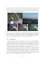
1/6 74LVC14
3.3 V
5.1 kΩ
77
IRQ0#
4.7µF
Fig. 3 – Schematic (left) and implementation (right) of the debounce circuit used to trigger a
single hardware interrupt when a push-button is pressed.
of the kernel ported to the Coldfire processor, as well as the communication with user space. A
fully functional version of the module is available at [12].
8
#define IRQ_DEFAULT 66
static int uc_int_major = 6;
static int uc_int_open (struct inode *inode, struct file *file)
{[...]
tmp = *((volatile unsigned long *) (MCF_MBAR + MCFSIM_ICR1));
tmp |= 0x0f000000;
*(volatile unsigned long *) (MCF_MBAR + MCFSIM_ICR1) = tmp;
if ((retval = request_irq (uc_int_irq, uc_int_irqhandler, SA_INTERRUPT, "uc_int", dev)))
{dbg("unable to assign irq %d", uc_int_irq);goto exit_sem;}
[...]
}
static struct file_operations uc_int_fops =
{owner: THIS_MODULE,
read: uc_int_read,
open: uc_int_open,
release: uc_int_release,
};
static void uc_int_irqhandler (int irq, void *dev_id, struct pt_regs *regs)
{unsigned long tmp;
[...]
tmp = *((volatile unsigned long *) (MCF_MBAR + MCFSIM_ICR1));
static ssize_t uc_int_read (struct file *file, char *buffer, size_t count, loff_t *ppos)
{unsigned long tmp[4];
[...]
interruptible_sleep_on (&dev->uc_int_queue); /* sleep until a interrupt occurs */
memcpy ((void *) tmp, (void *) (MCF_MBAR + MCFSIM_ICR1), sizeof (tmp));
[...]
}
/* disable interrupts */
tmp &=0xf8ffffff;*(volatile unsigned long *)(MCF_MBAR+MCFSIM_ICR1)=tmp;
/* we ack this interruption to the hardware */
tmp |=0x08000000;*(volatile unsigned long *)(MCF_MBAR+MCFSIM_ICR1)=tmp;
/* and wake up user application waiting for a read */
wake_up_interruptible (&dev->uc_int_queue);
/* restore interrupts */
tmp |= 0x0f000000;*(volatile unsigned long *)(MCF_MBAR+MCFSIM_ICR1)=tmp;
[...]
/* the realease method is call when user want close () the device */
static int uc_int_release (struct inode *inode, struct file *file)
{[...]
free_irq (dev->uc_int_irq, NULL);
[...]
}
}
This module registers the interrupt service routine for INT2 (in the Motorola naming convention) thanks to the function request irq(). A user-space client then listens through an interface
(/dev/uc int defined with a major number of 6 by running the command mknod uc int c 6 0
in romfs/dev of the uClinux directory) : the function read() being blocking, the execution of the
client only continues when a hardware interrupt is triggered. The module then transfers to the
client the 16 bytes displaying the values to which registers INTiPL, i ∈ [1..4] are set (i.e. most
significant word of the ICR1 register).
#include
#include
#include
#include
#include
#include
#include
<stdio.h>
<stdlib.h>
<sys/types.h>
<sys/stat.h>
<fcntl.h>
<asm/coldfire.h>
// defines MCF_MBAR
<asm-m68knommu/m5272sim.h> // defines PADDR
fd=open("/dev/uc_int",O_RDONLY);
while (1) {read(fd,i,16);
for (n=0;n<16;n++) printf("%x ",((char)(i[n]))&0xff);
printf("\n");
}
return(0);
int main(int argc,char **argv)
{char i[16];int fd;char n;
}
The steps for compiling this module are described in a document available in
linux-2.4.x/Documentation/kbuild in the uClinux directory structure (most importantly config-language.txt
and makefiles.txt which describe the modifications to be brought to Config.in and the Makefile
in order to include the new module in the compilation sequence). In summary, we create a directory named uc int in the linux-2.4.x/drivers/char directory of uClinux, in which we place the
source code of our module and a Makefile including the lines obj-$(CONFIG UC INT) := uc int.o
and include $(TOPDIR)/Rules.make. Then in the Makefile of the char directory we add
ifeq ($(CONFIG UC INT),m)
subdir-$(CONFIG UC INT) += uc int
obj-$(CONFIG UC INT) += uc int/uc int.o
endif
and finally in linux-2.4.x/drivers/char/Config.in we add tristate ’uc int driver’ CONFIG UC INT
to add a new entry in the kernel configuration menu. A make to build the kernel then creates the
module uc int.o which is appended to the kernel by executing an insmod as would be done
classically under linux.
10
Results
We have attached our circuits including the uCdimm5272 board, two black and white webcams
as presented previously, motorized by a servo motor (controled by the PWM), an Olympus C-860L
digital camera (remote contolled through an RS232 link [14]) and a wifi module DLink DWL-810+
to a gondola attached to a 2.60 m-diameter tethered gas balloon inflated with helium (European
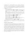
Balloon Corporation, Belgique) [15]. The wifi link used to transmit images to the ground station
and to control the digital camera works when no obstacle is present in the path at a distance of
more than 150 m (Fig. 4). The lack of analog to digital converter to monitor the environment
9
is compensated for by connecting to the second RS232 port of the uCdimm a microcontroler
(ADuC814 [16]) used to read an analog value (in our case the temperature of the gondola) and
store the result in a file mounted by NFS from a server located on the ground. All these devices
are powered by a 2000 mA.h Lithium-polymer battery (T2M Powerhouse) providing an autonomy
of about 1 h. The whole gondola weights about 1 kg.
+
=
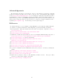
Fig. 4 – Top : aerial photography of the parc of the Besançon observatory (left) and sunset on the
École Nationale Supérieure de Mécanique et des Microtechiques (ENSMM), the new Maison des
Microtechniques under construction and the buildings of the CROUS (right). Bottom : snapshot
of the Laboratoire de Physique et Métrologie des Oscillateurs (FEMTO-ST/LPMO), Besançon,
France, and resulting stereoscopic image to be watched with red/blue glasses [17].
11
Conclusion
We have presented the successive steps during the development of our embedded application
– image acquisition and transfer from a tethered balloon – based on uClinux. We have first become familiar with the development tools (bootloader, cross-compilation, transfer of the resulting
programs by NFS) before approaching the hardware interfacing issues and software access to the
input/output ports. The main point of using the Arcturus Networks uCdimm 5272 board is the
availability, at minimal cost and power consumption, of a decent computational power and the
availability of all the development tools and libraries provided by linux.
Several manufacturers are now providing new boards with new functionalities and smaller
dimensions proving new application opportunities : we have just bought an SSV DIL/NetPC
DNP/5280 [18] whose presentation will be the subject of another article : this board is based on
the Coldfire 5282 which provides several useful peripherals which were not available of the 5272 –
for example analog to digital converters, an I2 C bus or a CAN bus – as well as a connector much
more convenient to use (DIL64). Despite their naming similarities, the programming model is very
different than that of the 5272 since like on other processors with an MMU, we must go to kernel
space to access registers controling hardware functionalities on the 5282.
10
Acknowledgements
We acknowledge the support of F. Vernotte, director of the Besançon observatory, for kindly
hosting the student association Projet Aurore, and the help of H. Bässmann (The Imaging
Source, http://www.theimagingsource.com/) for offering two identical webcam lenses (ref. Adogon L12mf3.6f) so that we could achieve stereoscopic imaging. Vincent Giordanno and the “oscillator metrology” team of the FEMTO-ST/LPMO laboratory have provided the helium for the
tethered balloon. The association for the promotion of opensource software in Franche-Comté –
Sequanux (www.sequanux.org) – is acknowledged for its logistics support.
Références
[1] “Linux embarqué : le projet uClinux”, Linux Magazine, pp.16-22 (Février 2002) [in French]
[2] “Linux et le système sur silicium”, Linux Magazine, pp.50-59 (Avril 2005) [in French]
[3] M. Opdenacker, “Embedded Linux kernel and driver development”, disponible à http://
free-electrons.com
[4] http://www.arcturusnetworks.com/coldfire5272.shtml
[5] http://friedtj.free.fr/h8eng.pdf
[6] MCF5272 ColdFire Integrated Microprocessor User Manual (MCF5272UM), disponible à
http://www.freescale.com/webapp/sps/site/prod_summary.jsp?code=MCF5272
[7] http://www.digikey.com, reference 54697-1440
[8] http://www.uclinux.org/pub/uClinux/uclinux-elf-tools/
m68k-elf-tools-20030314.sh
[9] http://www.uclinux.org/pub/uClinux/uclinux-elf-tools/gcc-3/
[10] http://www.uclinux.org/pub/uClinux/dist/
[11] http://www.seattlerobotics.org/encoder/200009/qcam.html
[12] http://projets.sequanux.org/membres/sim/uclinux-webcam/
[13] J. Corbet, A. Rubini & G. Kroah-Hartman, Linux Device Drivers, 3rd Edition, O’Reilly Ed.
(2005)
[14] http://photopc.sourceforge.net/protocol.html
[15] http://projetaurore.assos.univ-fcomte.fr/ballon/
[16] http://friedtj.free.fr/aduc816.pdf
[17] W.R. Newcott, Return to Mars et J.B. MacInnis, E. Kristof ,Titanic : Tragedy in Three
Dimensions, National Geographic, Aout 1998
[18] http://www.dilnetpc.com/dnp0038.htm
11