1
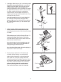
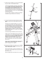
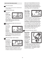
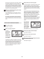
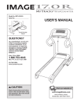
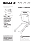
Model No. IMEL2105.1
Serial No.
USER'S MANUAL
Serial Number
Decal
QUESTIONS?
As a manufacturer, we are committed to providing complete
customer satisfaction. If you
have questions, or if parts are
damaged or missing, PLEASE
CONTACT OUR CUSTOMER
Visit our
SERVICE DEPARTMENT
DIRECTLY.
website at
www.proform.com
CALL TOLL-FREE:
new products, prizes,
1-800-753-4645
fitness tips, and much more!
Mon.–Fri., 6 a.m.–6 p.m. MST
Visit our website at
www.weslo.com
new products, prizes,
fitness tips, and much more!
ON THE WEB:
www.iconservice.com
Visit our website at
Visit our website at
www.healthrider.com
www.jumpking.com
new products, prizes,
fitness tips, and much more!
new products, prizes,
fitness tips, and much more!
CAUTION
Visit our website at
Read all precautions and
instructions in this manual
before using thiswww.nordictrack.com
equipment.
Keep this manual for future
new products, prizes,
reference.
fitness tips, and much more!
Visit our website at
www.imagefitness.com
new products, prizes,
fitness tips, and much more!
TABLE OF CONTENTS
IMPORTANT PRECAUTIONS . . . . . . . . . . . . . . . . . . . . . . . . . . . . . . . . . . . . . . . . . . . . . . . . . . . . . . . . . . . . . . . .3
BEFORE YOU BEGIN . . . . . . . . . . . . . . . . . . . . . . . . . . . . . . . . . . . . . . . . . . . . . . . . . . . . . . . . . . . . . . . . . . . . . .4
ASSEMBLY . . . . . . . . . . . . . . . . . . . . . . . . . . . . . . . . . . . . . . . . . . . . . . . . . . . . . . . . . . . . . . . . . . . . . . . . . . . . . . .5
HOW TO USE THE ELLIPTICAL EXERCISER . . . . . . . . . . . . . . . . . . . . . . . . . . . . . . . . . . . . . . . . . . . . . . . . . . .9
MAINTENANCE AND TROUBLESHOOTING . . . . . . . . . . . . . . . . . . . . . . . . . . . . . . . . . . . . . . . . . . . . . . . . . . .14
CONDITIONING GUIDELINES . . . . . . . . . . . . . . . . . . . . . . . . . . . . . . . . . . . . . . . . . . . . . . . . . . . . . . . . . . . . . . .15
PART LIST . . . . . . . . . . . . . . . . . . . . . . . . . . . . . . . . . . . . . . . . . . . . . . . . . . . . . . . . . . . . . . . . . . . . . . . . . . . . . .18
EXPLODED DRAWING . . . . . . . . . . . . . . . . . . . . . . . . . . . . . . . . . . . . . . . . . . . . . . . . . . . . . . . . . . . . . . . . . . . .19
HOW TO ORDER REPLACEMENT PARTS . . . . . . . . . . . . . . . . . . . . . . . . . . . . . . . . . . . . . . . . . . . . .Back Cover
LIMITED WARRANTY . . . . . . . . . . . . . . . . . . . . . . . . . . . . . . . . . . . . . . . . . . . . . . . . . . . . . . . . . . . . . .Back Cover
IMAGE is a registered trademark of ICON IP, Inc.
2
IMPORTANT PRECAUTIONS
WARNING:
To reduce the risk of serious injury, read the following important precautions before using the elliptical exerciser.
1. Read all instructions in this manual and all
warnings on the elliptical exerciser before
using the elliptical exerciser.
7. The elliptical exerciser should not be used
by persons weighing more than 250 pounds.
2. It is the responsibility of the owner to ensure
that all users of the elliptical exerciser are
adequately informed of all precautions.
8. Wear appropriate exercise clothes when
using the elliptical exerciser. Always wear
athletic shoes for foot protection while exercising.
3. The elliptical exerciser is intended for
home use only. Do not use the elliptical
exerciser in a commercial, rental, or institutional setting.
9. When mounting and dismounting the elliptical exerciser, always hold the handlebars
and step onto and off the pedal that is in the
lowest position.
4. Keep the elliptical exerciser indoors, away
from moisture and dust. Place the elliptical
exerciser on a level surface, with a mat
beneath it to protect the floor or carpet.
Make sure that there is enough clearance
around the elliptical exerciser to mount, dismount, and use it.
10. The pulse sensor is not a medical device.
Various factors may affect the accuracy of
heart rate readings. The pulse sensor is
intended only as an exercise aid in determining heart rate trends in general.
11. Keep your back straight when using the elliptical exerciser; do not arch your back.
5. Inspect and properly tighten all parts regularly. Replace any worn parts immediately.
12. If you feel pain or dizziness while exercising,
stop immediately and cool down.
6. Keep children under 12 and pets away from
the elliptical exerciser at all times.
13. When you stop exercising, allow the pedals
to slowly come to a stop.
WARNING:
Before beginning this or any exercise program, consult your physician.
This is especially important for persons over the age of 35 or persons with pre-existing health problems. Read all instructions before using. ICON assumes no responsibility for personal injury or
property damage sustained by or through the use of this product.
3
BEFORE YOU BEGIN
Congratulations for selecting the new IMAGE® 8.0
low-impact elliptical exerciser. The IMAGE 8.0 is an
incredibly smooth exerciser that moves your feet in a
natural elliptical path, minimizing the impact on your
knees and ankles. Welcome to a whole new world of
natural, elliptical-motion exercise.
number and serial number before calling. The model
number is IMEL2105.1. The serial number can be
found on a decal attached to the elliptical exerciser
(see the front cover of this manual).
To avoid a registration fee for any service needed
under warranty, you must register the elliptical
exerciser at www.iconservice.com/registration.
For your benefit, read this manual carefully before
you use the elliptical exerciser. If you have additional questions, see the front cover of this manual. To
help us assist you, please note the product model
Before reading further, please familiarize yourself with
the parts that are labeled in the drawing below.
Book Holder
Handlebar
Console
Handgrip Pulse Sensor
Water Bottle Holder
(Bottle is not included)
FRONT
Upright
Wheel
Side Shield
Pedal
Pedal Disk
BACK
Pedal Arm
The decal shown at the left has been placed on the
elliptical exerciser. If the decal is missing, or if it is not
legible, call the toll-free telephone number on the front
cover of this manual and order a free replacement
decal. Apply the decal in the location shown.
4
ASSEMBLY
To hire an authorized service technician to assemble the elliptical exerciser, call toll-free 1-800-445-2480.
Assembly requires two persons. Place all parts of the elliptical exerciser in a cleared area and remove the
packing materials. Do not dispose of the packing materials until assembly is completed.
Assembly requires a phillips screwdriver
mallet
.
, two adjustable wrenches
, and a rubber
See the drawings below to identify the small parts needed for assembly. The number in parenthesis below
each drawing is the key number of the part, from the PART LIST on page 18. The number following the key
number is the quantity needed for assembly. Note: Some small parts may have been pre-assembled. If a
part is not found in the parts bag, check to see if it has been pre-assembled.
M8 Split
Washer (74)–7
M10 Nylon
Locknut (29)–2
M8 Large
Washer (17)–4
M10 Split
Washer (67)–8
Small Wave
Washer (90)–2
Wave Washer
(85)–2
M5 x 15mm M8 x 19mm Button
M4 x 19mm
M4 x 16mm
Screw (22)–4
Screw (66)–4 Screw (39)–2 Screw (89)–1
M10 x 22mm Button
Screw (21)–4
M8 x 25mm Button
Screw (57)–3
M8 x 46mm Button
Screw (20)–4
M8 x 42mm Button
Bolt (50)–4
Bolt Set (27)–2
M8 Nylon
Locknut (46)–4
M10 x 58mm Button Screw (19)–4
M10 x 105mm Carriage Bolt (34)–2
5
1. Attach the Rear Stabilizer (4) to the Frame (1) with
two M10 x 105mm Carriage Bolts (34) and two M10
Nylon Locknuts (29).
1
29
1
29
4
2. Hold the Lower Wire Harness (65) in the indicated
slot in the Frame (1), and insert the Front Stabilizer (3)
into the Frame. Make sure that the Front Stabilizer
is oriented as shown. Be careful to avoid pinching
the Lower Wire Harness. Carefully tip the elliptical
exerciser onto one side, and attach the Front
Stabilizer with four M10 x 22mm Button Screws (21)
and four M10 Split Washers (67).
34
2
65
Slot
3
1
67
67
21
3. While another person holds the Upright (2) near the
Frame (1), connect the Upper Wire Harness (79) to
the Lower Wire Harness (65). Carefully pull the
upper end of the Upper Wire Harness to remove
any slack, and set the Upright on the Front Stabilizer
(3) and the Frame. Be careful to avoid pinching the
Wire Harnesses. Align the holes in the Upright with
the holes in the Front Stabilizer and the Frame.
3
2
79
65
3
1
Carefully tip the elliptical exerciser onto one side, and
attach the Upright (2) to the Front Stabilizer (3) and
the Frame (1) with four M10 x 58mm Button Screws
(19) and four M10 Split Washers (67).
67
67
19
4. Gently separate the Left and Right Frame Covers (30,
81). Hold the Frame Covers around the Upright (2)
and the Frame (1). Firmly press the Frame Covers
together.
4
81
2
30
1
6
5. If the Upper Wire Harness (79) is not already routed
through the Console Bracket (26), locate the wire
extending from the bottom of the Console Bracket.
Carefully pull the upper end of the Upper Wire
Harness to remove any slack, and tie the wire around
the Upper Wire Harness as shown in the inset drawing. Next, carefully pull the wire up through the
Console Bracket until the Upper Wire Harness is
extending from the top of the Console Bracket. Then,
untie the wire and discard it.
5
Wire
26
79
79
Insert the Console Bracket (26) into the Upright (2).
Be careful to avoid pinching the Upper Wire
Harness (79). Attach the Console Bracket with three
M8 x 25mm Button Screws (57) and three M8 Split
Washers (74).
57
74
57
74
2
6. If the end of the indicated ground wire is not
already attached to the Console Bracket (26),
attach the ground wire with an M5 x 15mm Screw (89)
as shown.
6
5
Console
Wires
While another person holds the Console (5) near the
Console Bracket (26), connect the wires on the
Console to the Upper Wire Harness (79) and the
Pulse Wire Harness (80). Insert the Wire Harnesses
down into the Console Bracket.
79
80
89
Attach the Console (5) to the Console Bracket (26)
with four M4 x 16mm Screws (66). Be careful to
avoid pinching the wire harnesses.
26
Ground
Wire
66
63
Attach the Water Bottle Holder (63) to the Upright (2)
with two M4 x 19mm Screws (39).
2
39
7. The Console (5) requires four “D” batteries (not
included); alkaline batteries are recommended.
7
Look under the Console (5) and locate the battery
cover. (Note: For clarity, the drawing shows the
Console removed from the elliptical exerciser.) Press
the tab on the battery cover and remove the battery
cover. Next, insert four batteries into the Console;
make sure that the batteries are oriented as
shown by the diagram inside of the Console.
Then, reattach the battery cover to the Console.
5
Batteries
Battery
Cover
7
8. Identify the Left Handlebar (9) and the Left Handlebar
Leg (73), which are marked with stickers.
8
Insert the Left Handlebar (9) into the Left Handlebar
Leg (73). Make sure that the indicated tube on the
Left Handlebar and the hexagonal holes in the
Left Handlebar Leg are on the same side. Attach
the Left Handlebar with two M8 x 42mm Button Bolts
(50) and two M8 Nylon Locknuts (46). Do not tighten
the Button Bolts yet.
9
Tube
46
50
Hexagonal
Holes
Attach the Right Handlebar (not shown) to the Right
Handlebar Leg (not shown) in the same way.
73
9. Insert the Pivot Axle (38) into the Upright (2). Apply a
generous amount of the included grease to the Pivot
Axle.
9
10
Identify the Left and Right Handlebars (9, 10), which
are marked with stickers. Have another person hold
the Left Handlebar near the left end of the Pivot Axle
(38). Slide a Handlebar Spacer (25) onto the indicated
tube on the Left Handlebar; make sure that the
Handlebar Spacer is oriented as shown, with the
smaller cutout on top. Then, slide the Left Handlebar
onto the Pivot Axle.
23
82
9
Assemble the Right Handlebar (10) in the same way.
Grease
38
17 90
22
Tighten an M8 x 19mm Button Screw (22) with an M8
Large Washer (17) and a Small Wave Washer (90) into
each end of the Pivot Axle (38). Make sure the Wave
Washers are on the Pivot Axle. Orient the two
Handlebar Caps (23) as shown, and press the small
tabs on the Handlebar Caps into the two Handlebar
Spacers (25).
22
90 17
25
25
82
Tube
2
23
Tab
Gently separate the two Upright Covers (82). Hold the
Upright Covers around the Upright (2), and firmly
press the Upright Covers together.
10. Identify the Left Pedal (13), which has an “L” molded
into its bottom surface, and the Left Pedal Arm (14),
which is marked with a sticker.
10
13
Attach the Left Pedal (13) to the Left Pedal Arm (14)
with two M8 x 46mm Button Screws (20) and two M8
Split Washers (74).
14
74
Attach the Right Pedal (not shown) in the same way.
74
20
8
11. Apply a thin film of grease to the shaft of a Bolt Set
(27) and to the axle on the Left Crank Arm (36).
11
73
Slide the Left Pedal Arm (14) and a Wave Washer
(85) onto the axle on the Left Crank Arm (36). Next,
tighten an M8 x 19mm Button Screw (22) with an M8
Large Washer (17) into the end of the axle.
Attach the Left Handlebar Leg (73) to the Left Pedal
Arm (14) with the Bolt Set (27).
Grease
16
27
14
36
Attach the Right Pedal Arm (16) to the right side of
the elliptical exerciser in the same way.
17
22
See step 8 on page 8. Tighten the M8 x 42mm Button
Bolts (50). Make sure that the M8 Nylon Locknuts
(46) are seated in the hexagonal holes.
85
Grease
12. Make sure that all parts of the elliptical exerciser are properly tightened. Place a mat under the elliptical
exerciser to protect the floor or carpet from damage.
HOW TO USE THE ELLIPTICAL EXERCISER
HOW TO EXERCISE ON THE ELLIPTICAL
EXERCISER
Handlebars
To mount the elliptical exerciser, firmly hold the handlebars and carefully step onto the pedal that is in the
lowest position. Next, step onto the other pedal. Push
the pedals until they begin to move with a continuous
motion. Note: The pedal disks can turn in either
direction. It is recommended that you turn the
pedal disks in the direction shown at the right;
however, for variety, you can turn the pedal disks
in the opposite direction.
Pedal
To dismount the elliptical exerciser, allow the pedals
to come to a complete stop. CAUTION: The elliptical
exerciser does not have a freewheel; the pedals
will continue to move until the flywheel stops.
When the pedals are stationary, step off the highest
pedal first. Then, step off the lowest pedal.
Pedal
Disk
9
CONSOLE DRAWING
FEATURES OF THE CONSOLE
The advanced console offers a selection of features
designed to make your workouts more effective. When
the manual mode of the console is selected, the resistance of the pedals can be adjusted with the touch of
a button. As you exercise, the console will display continuous exercise feedback. You can even measure
your heart rate using the built-in handgrip pulse sensor.
To track your walking exercise, the console features a
new MyTracks™ StepCounter that counts the number of
steps that you pedal during each workout. In addition,
the console offers a MyTracks™ StepCounter program
that allows you to enter the number of steps that you
plan to pedal, and counts down the steps as you
exercise.
Resistance Programs
Note: The console requires four “D” batteries (not
included). If batteries have not been installed, see
step 7 on page 7. If there is a sheet of clear plastic
on the face of the console, remove it.
The console also features four resistance programs.
Each program automatically controls the resistance of
the elliptical exerciser as it guides you through an
effective workout.
MyTracks™ StepCounter
To use the manual mode of the console, follow the
steps beginning on page 11. To use a resistance program, see page 12. To use the MyTracks™
StepCounter program, see page 13.
Walking is one of the most popular exercises worldwide. Walking does not require advanced conditioning
or special skills, yet it produces numerous benefits,
such as increased calorie burning, a slimmer waist,
toned muscles, enhanced energy and stamina, lower
blood pressure, and reduced stress.
10
when you use the handgrip pulse sensor. The
display will also show the resistance level for a
few seconds each time the resistance setting
changes. Note: When a resistance program is
selected, the display will show the time remaining
in the program instead of the elapsed time. To
reset the display, press the On/Reset button.
HOW TO USE THE MANUAL MODE
1
Turn on the console.
To turn on the console, press the On/Reset button
or begin pedaling.
2
Note: The display can show
speed and distance in either
miles or kilometers. To change
the unit of measurement, first
hold down the Resistance Program button for
about three seconds; “E MPH” (English miles per
hour) or “M Kp/H” (metric kilometers per hour)
will appear in the display to show which unit of
measurement is selected. To change the unit of
measurement, press the Resistance increase button. The display will also show the total number
of steps pedaled by all users of the elliptical exerciser (if a “K” appears beside the number, multiply the number by 1,000) and the total number of
miles or kilometers pedaled. When you are finished viewing this information, press the
Resistance Program button again.
Select the manual mode.
Each time the
console is
turned on, the
manual mode
will be selected.
If you have
selected a program, select the
manual mode by pressing the Resistance
Program button repeatedly until only zeros
appear in the display.
3
Begin pedaling and adjust the resistance of
the pedals.
As you pedal,
adjust the resistance of the
pedals as
desired by
pressing the
Resistance
increase and
decrease buttons. There are ten resistance levels. Note: After the buttons are pressed, it will
take a few seconds for the pedals to reach the
selected setting.
4
5
Measure your heart rate if desired.
Note: If there
are thin sheets
of plastic on
the metal contacts on the
handgrip pulse
sensor, peel off
the plastic. To
Metal
use the handgrip
Contacts
pulse sensor,
stop pedaling
and hold the
handgrip pulse
sensor with your palms resting on the metal contacts. Avoid moving your hands. When your
pulse is detected, the heart-shaped indicator in
the display will flash each time your heart beats,
one or two dashes (– –) will appear, and then
your heart rate will be shown.
Follow your progress with the display.
As you pedal,
the display will
show the number of steps you
have pedaled,
your pedaling
pace (in revolutions per minute
[RPM]), your pedaling speed, the elapsed time,
the distance that you have pedaled, and the
approximate number of calories you have burned.
In addition, the display will show your heart rate
11
For the most accurate heart rate reading, continue
to hold the handgrip pulse sensor for about 15
seconds. Note: When you first hold the handgrip
pulse sensor, the console will display your heart
rate continuously for 15 seconds. The console will
then display your heart rate along with your pedaling pace and your pedaling speed.
6
3
To start the program, simply begin pedaling. Each
resistance program consists of 30 one-minute
periods. One resistance setting is programmed for
each period. Note: The same resistance setting
may be programmed for two or more consecutive
periods.
When you are finished exercising, the console
will automatically turn off.
At the end of each one-minute period, the time
will flash in the display, and the resistance of the
pedals will automatically change if a different
resistance setting is programmed for the next
period. Note: If the resistance level is too high or
too low, you can change it by pressing the
Resistance increase or decrease button.
However, when the current period ends, the resistance level will automatically change if a different
resistance setting is programmed for the next
period.
If you stop pedaling for a few seconds, the console will pause and the time will begin to flash in
the display.
If the pedals are not moved and the console buttons are not pressed for a few minutes, the console will automatically turn off to conserve the batteries.
The console will
display the time
remaining in the
program. If you
continue pedaling after the program is completed, the display
will continue to show your exercise feedback.
HOW TO USE A RESISTANCE PROGRAM
1
Turn on the console.
See step 1 on page 11.
2
Begin pedaling to start the program.
Select a resistance program.
To select a
resistance program, press the
Resistance
Program button
repeatedly until
“P1,” “P2,” “P3,”
or “P4” appears
in the display.
4
Follow your progress with the display.
See step 4 on page 11.
5
Measure your heart rate if desired.
See step 5 on page 11.
6
The diagrams numbered 1 through 4 on the right
side of the console show how the resistance level
will change during the resistance programs. For
example, diagram number 3 shows that when
program 3 is selected, the resistance will gradually increase throughout the program, and then
decrease near the end.
When you are finished exercising, the console
will automatically turn off.
See step 6 on page 11.
12
weeks. IMPORTANT: Always exercise at an
intensity level and for a length of time that is
comfortable for you.
HOW TO USE THE MYTRACKSTM
STEPCOUNTER PROGRAM
1
3
Turn on the console.
As you exercise, adjust the resistance of the elliptical exerciser as desired by pressing the
Resistance increase or decrease buttons.
See step 1 on page 11.
2
Begin pedaling to start the program.
Select the MyTracks™ StepCounter program.
The display will
show the number
of steps still to be
pedaled. If you
continue pedaling
after the program
is completed, the
display will continue to show your exercise feedback; however,
the display will not show the number of steps you
have pedaled, until you select the manual mode
or a new program.
Press the
10,000 Steps
Program button;
the MyTracks™
StepCounter
program will be
selected and a
goal of 10,000
steps will appear in the display.
Depending on your fitness level, you may desire
to pedal fewer than or more than 10,000 steps. To
change the goal, press the Steps Target increase
and decrease buttons. Each time a button is
pressed, the goal will change by 500 steps. Note:
The goal can be changed either before or after
the program is started.
4
Follow your progress with the display.
See step 4 on page 11.
Note: To find an appropriate starting goal, complete a workout with the manual mode selected
(see page 11), and note the number of steps that
you pedal during your workout. Then, round that
number up to the nearest 500 steps. This can be
a starting goal. As your fitness level improves, you
can increase the goal by 500 steps every few
13
5
Measure your heart rate if desired.
See step 5 on page 11.
6
When you are finished exercising, the console
will automatically turn off.
See step 6 on page 11.
MAINTENANCE AND TROUBLESHOOTING
Remove the indicated Screws (62) from the Right
Side Shield (7). Remove the indicated Screws (66)
from both Side Shields (6, 7). Lift the Side Shields off
the elliptical exerciser.
Inspect and properly tighten all parts of the elliptical
exerciser regularly. Replace any worn parts immediately.
The elliptical exerciser can be wiped clean with a soft
cloth and mild detergent. Do not use abrasives or
solvents. To prevent damage to the console, keep
liquids away from the console and keep the console
out of direct sunlight.
7
6
When storing the elliptical exerciser, remove the batteries from the console. Keep the elliptical exerciser in
a clean, dry location, away from moisture and dust.
CONSOLE TROUBLESHOOTING
66
If the console does not function properly, the batteries
should be replaced. To replace the batteries, see
assembly step 7 on page 7.
62
66
HANDGRIP PULSE SENSOR TROUBLESHOOTING
If the handgrip pulse sensor does not function properly, see step 5 on page 11.
Next, locate the Reed Switch (77). Turn the Flywheel
(41) until the Magnet (43) is aligned with the Reed
Switch. Loosen, but do not remove, the indicated
Screw (66). Slide the Reed Switch slightly closer to or
away from the Magnet, and then retighten the Screw.
Rock the Flywheel forward and back just enough that
the Magnet passes the Reed Switch repeatedly.
Repeat until the console displays correct feedback.
When the Reed Switch is correctly adjusted, reattach
the side shields and the pedal disks.
HOW TO ADJUST THE REED SWITCH
If the console does not display correct feedback, the
reed switch should be adjusted. To adjust the reed
switch, first remove the indicated Screws (62) from
both Pedal Disks (8). Pull both Pedal Disks out of the
Side Shields (6, 7). Rotate the right Pedal Disk so you
are able to see beneath it.
7
6
8
41
43
62
66
8
77
14
CONDITIONING GUIDELINES
Fat Burning
WARNING:
To burn fat effectively, you must exercise at a relatively low intensity level for a sustained period of time.
During the first few minutes of exercise, your body
uses easily accessible carbohydrate calories for energy. Only after the first few minutes of exercise does
your body begin to use stored fat calories for energy. If
your goal is to burn fat, adjust the intensity of your
exercise until your heart rate is near the lowest number or the middle number in your training zone as you
exercise.
Before beginning this or any exercise program, consult your physician. This is especially important for individuals over the age
of 35 or individuals with pre-existing health
problems.
The pulse sensor is not a medical device.
Various factors may affect the accuracy of
heart rate readings. The pulse sensor is
intended only as an exercise aid in determining heart rate trends in general.
Aerobic Exercise
If your goal is to strengthen your cardiovascular system, your exercise must be “aerobic.” Aerobic exercise
is activity that requires large amounts of oxygen for
prolonged periods of time. This increases the demand
on the heart to pump blood to the muscles, and on the
lungs to oxygenate the blood. For aerobic exercise,
adjust the intensity of your exercise until your heart
rate is near the highest number in your training zone.
The following guidelines will help you to plan your
exercise program. Remember that proper nutrition and
adequate rest are essential for successful results.
EXERCISE INTENSITY
Whether your goal is to burn fat or to strengthen your
cardiovascular system, the key to achieving the
desired results is to exercise with the proper intensity.
The proper intensity level can be found by using your
heart rate as a guide. The chart below shows recommended heart rates for fat burning, maximum fat burning, and cardiovascular (aerobic) exercise.
WORKOUT GUIDELINES
Each workout should include the following three parts:
A warm-up, consisting of 5 to 10 minutes of stretching
and light exercise. A proper warm-up increases your
body temperature, heart rate, and circulation in preparation for exercise.
Training zone exercise, consisting of 20 to 30 minutes of exercising with your heart rate in your training
zone. (During the first few weeks of your exercise program, do not keep your heart rate in your training
zone for longer than 20 minutes.)
A cool-down, with 5 to 10 minutes of stretching. This
will increase the flexibility of your muscles and will
help to prevent post-exercise problems.
To find the proper heart rate for you, first find your age
at the bottom of the chart (ages are rounded off to the
nearest ten years). Next, find the three numbers above
your age; the three numbers are your “training zone.”
The lowest number is the recommended heart rate for
fat burning; the middle number is the recommended
heart rate for maximum fat burning; and the highest
number is the heart rate for aerobic exercise.
EXERCISE FREQUENCY
To maintain or improve your condition, plan three workouts each week, with at least one day of rest between
workouts. After a few months of regular exercise, you
may complete up to five workouts each week, if
desired. The key to success is make exercise a regular and enjoyable part of your everyday life.
15
SUGGESTED STRETCHES
1
The correct form for several basic stretches is shown at the
right. Move slowly as you stretch—never bounce.
1. Toe Touch Stretch
Stand with your knees bent slightly and slowly bend forward
from your hips. Allow your back and shoulders to relax as you
reach down toward your toes as far as possible. Hold for 15
counts, then relax. Repeat 3 times. Stretches: Hamstrings, back
of knees, and back.
2
2. Hamstring Stretch
Sit with one leg extended. Bring the sole of the opposite foot
toward you and rest it against the inner thigh of your extended
leg. Reach toward your toes as far as possible. Hold for 15
counts, then relax. Repeat 3 times for each leg. Stretches:
Hamstrings, lower back, and groin.
3
3. Calf/Achilles Stretch
With one leg in front of the other, reach forward and place your
hands against a wall. Keep your back leg straight and your back
foot flat on the floor. Bend your front leg, lean forward, and
move your hips toward the wall. Hold for 15 counts, then relax.
Repeat 3 times for each leg. To cause further stretching of the
achilles tendons, bend your back leg as well. Stretches: Calves,
achilles tendons, and ankles.
4. Quadriceps Stretch
With one hand against a wall for balance, reach back and grasp
one foot with your other hand. Bring your heel as close to your
buttocks as possible. Hold for 15 counts, then relax. Repeat 3
times for each leg. Stretches: Quadriceps and hip muscles.
16
4
NOTES
17
PART LIST—Model No. IMEL2105.1
Key No. Qty.
1
2
3
4
5
6
7
8
9
10
11
12
13
14
15
16
17
18
19
20
21
22
23
24
25
26
27
28
29
30
31
32
33
34
35
36
37
38
39
40
41
42
43
44
45
46
47
1
1
1
1
1
1
1
2
1
1
2
1
1
1
2
1
4
4
4
4
4
4
2
6
2
1
2
4
4
1
2
2
2
2
2
1
1
1
2
2
1
2
1
1
1
7
2
Description
R0805A
Key No. Qty.
Frame
Upright
Front Stabilizer
Rear Stabilizer
Console
Left Side Shield
Right Side Shield
Pedal Disc
Left Handlebar
Right Handlebar
Foam Grip
Right Pedal
Left Pedal
Left Pedal Arm
M5 Nut
Right Pedal Arm
M8 Large Washer
Rear Pedal Arm Bushing
M10 x 58mm Button Screw
M8 x 46mm Button Screw
M10 x 22mm Button Screw
M8 x 19mm Button Screw
Handlebar Cap
Handlebar Bushing
Handlebar Spacer
Console Bracket
Bolt Set
Front Pedal Arm Bushing
M10 Nylon Locknut
Left Frame Cover
Front Stabilizer Endcap
Wheel
M10 x 60mm Button Bolt
M10 x 105mm Carriage Bolt
Rear Stabilizer Endcap
Left Crank Arm
Pulley
Pivot Axle
M4 x 19mm Screw
Crank Bearing
Flywheel
Flywheel Bearing
Magnet
Flywheel Axle
M4 x 64mm Screw
M8 Nylon Locknut
Crank Screw
48
49
50
51
52
53
54
55
56
57
58
59
60
61
62
63
64
65
66
67
68
69
70
71
72
73
74
75
76
77
78
79
80
81
82
83
84
85
86
87
88
89
90
#
#
#
1
1
4
2
1
1
1
1
1
3
1
2
3
4
11
1
1
1
11
8
1
1
4
2
1
1
7
2
1
1
1
1
1
1
2
4
1
2
2
2
2
1
2
1
1
1
Description
Right Crank Arm
M6 x 20mm Bolt
M8 x 42mm Button Bolt
M6 x 16mm Button Bolt
“C” Magnet Bracket
“U” Bracket
“C” Magnet
Motor
Belt
M8 x 25mm Button Screw
Adjustment Cable
M6 Nylon Locknut
M6 Nut
M5 Nylon Locknut
M5 x 16mm Screw
Water Bottle Holder
M6 Large Washer
Lower Wire Harness
M4 x 16mm Screw
M10 Split Washer
Pulley Spacer
Reed Switch Clamp
Motor Washer
Handgrip Pulse Sensor/Wire
Right Handlebar Leg
Left Handlebar Leg
M8 Split Washer
M6 Eyebolt
Spring
Reed Switch
Reed Switch Bracket
Upper Wire Harness
Pulse Wire Harness
Right Frame Cover
Upright Cap
M5 x 12mm Bolt
Small Pulley Spacer
Wave Washer
M4 x 16mm Screw
“T”-bar Endcap
Handlebar Endcap
M5 x 15mm Screw
Small Wave Washer
Allen Wrench, Set
Grease
User’s Manual
Note: “#” indicates a non-illustrated part. Specifications are subject to change without notice. See the back cover
of this manual for information about ordering replacement parts.
18
EXPLODED DRAWING—Model No. IMEL2105.1
R0805A
88
89
26
11
71
10
22
87
71
87
82
17 23
24
86
74
74
38
66
56
24
74
9
22
23
66
24 25
46
57
17 24
90
50
24
88
11
5
72
57
82
60
59
65
46
25
24
46
80
2
63
41
53
79
60
50
73
32 33
27
31
27
46
32
33
60
76
43
12
3
81
62
31
67
28
67
27
28
19
21
67
18
74
85
47
48
68 66
69
36
18
47
77 78 62
29
84
37
45
62
8
34
62
62
7
62
66
8
66
66
19
35
4
29
15 58
35
62
62
66
18
1
6
66
85
74
19
19
17 22
18
20
40
74
17
22
74
70
61
14
20
16
40
30
28
83
70
55
13
62
59
28
29
46
49
54
42
42
75
75
51
52
44
39
90
27
64
HOW TO ORDER REPLACEMENT PARTS
To order replacement parts, see the front cover of this manual. To help us assist you, please be prepared to give
the following information when calling:
• the MODEL NUMBER of the product (IMEL2105.1)
• the NAME of the product (IMAGE 8.0 elliptical exerciser)
• the SERIAL NUMBER of the product (see the front cover of this manual)
• the KEY NUMBER and DESCRIPTION of the part(s) (see page 18)
LIMITED WARRANTY
ICON Health & Fitness, Inc. (ICON), warrants this product to be free from defects in workmanship and
material, under normal use and service conditions, for a period of ninety (90) days from the date of purchase. This warranty extends only to the original purchaser. ICON's obligation under this warranty is limited to replacing or repairing, at ICON's option, the product through one of its authorized service centers.
All repairs for which warranty claims are made must be pre-authorized by ICON. If the product is shipped
to a service center, freight charges to and from the service center will be the customer’s responsibility. For
in-home service, the customer will be responsible for a minimal trip charge. This warranty does not extend
to any product or damage to a product caused by or attributable to freight damage, abuse, misuse,
improper or abnormal usage or repairs not provided by an ICON authorized service center; products used
for commercial or rental purposes; or products used as store display models. No other warranty beyond
that specifically set forth above is authorized by ICON.
ICON is not responsible or liable for indirect, special or consequential damages arising out of or in connection with the use or performance of the product or damages with respect to any economic loss, loss
of property, loss of revenues or profits, loss of enjoyment or use, costs of removal or installation or other
consequential damages of whatsoever nature. Some states do not allow the exclusion or limitation of incidental or consequential damages. Accordingly, the above limitation may not apply to you.
The warranty extended hereunder is in lieu of any and all other warranties and any implied warranties of
merchantability or fitness for a particular purpose is limited in its scope and duration to the terms set forth
herein. Some states do not allow limitations on how long an implied warranty lasts. Accordingly, the above
limitation may not apply to you.
This warranty gives you specific legal rights. You may also have other rights which vary from state to state.
ICON HEALTH & FITNESS, INC., 1500 S. 1000 W., LOGAN, UT 84321-9813
Part No. 229459 R0805A
Printed in China © 2005 ICON IP, Inc.