1
Fast, strong and compliant pneumatic actuation for
dexterous tendon-driven hands
Vikash Kumar, Zhe Xu and Emanuel Todorov
Abstract—We describe a pneumatic actuation system for
dexterous robotic hands. It was motivated by our desire to
improve the ShadowHand system, yet it is quite universal and
indeed we are already using it with a second robotic hand
we have developed. Our actuation system allows us to move
the ShadowHand skeleton faster than a human hand (70 msec
limit-to-limit movement, 30 msec overall reflex latency), generate
sufficient forces (40 N at each finger tendon, 125N at each wrist
tendon), and achieve high compliance on the mechanism level
(6 grams of external force at the fingertip displaces the finger
when the system is powered.) This combination of speed, force
and compliance is a prerequisite for dexterous manipulation, yet
it has never before been achieved with a tendon-driven system,
let alone a system with 24 degrees of freedom and 40 tendons.
I. I NTRODUCTION
The unique capabilities of the human hand have long
inspired roboticist in their pursuit to develop manipulators with
similar ”dexterity”. We use this term here to refer to a combination of features: many independently-controlled degrees of
freedom (dofs), speed, strength and compliance. Simple and
isolated tasks such as grasping can of course be accomplished
by simpler devices. Nevertheless if robots are to perform a
wider range of tasks in less structured environments than what
is currently possible, they are likely to need manipulators
approaching human levels of dexterity.
The specific motivation behind the work described here was
somewhat accidental. We purchased a ShadowHand [1] with
the goal of developing and testing advanced control schemes
for object manipulation. After experimenting with it briefly we
concluded that, at least for the unit we received, the actuation
needs to be substantially faster and more compliant in order to
support dexterous object manipulation. We then disconnected
the actuators (air muscles) and observed that, when we pulled
on the tendons manually, the resulting finger motion was very
fast and compliant. Thus we decided to return the built-in
actuation system and develop an alternative. Upon further
reflection it became clear that such a development is very much
needed in the field. Indeed there exist multiple tendon-driven
hands (including the Utah-MIT hand [2], the ACT hand [3], as
well as cadaver hands [4]) that are comparable to human hands
kinematically, yet the lack of suitable actuation has hindered
control applications. Furthermore, 3D printing technology has
made it surprisingly easy to design and build new hands (and
possibly other mechanisms) with large numbers of joints and
tendons attached to them – see below. The question then is,
The authors are with the Departments of Computer Science & Engineering
and Applied Mathematics, University of Washington, WA 98195, USA
E-mail: {vikash, zhexu, todorov}@cs.washington.edu
how does one pull on all the tendons. Here we offer a solution
which we believe is quite universal and reflects the state-ofthe-art in actuation technology.
The rest of the paper is organized as follows. In the
next section we outline the design considerations and the
choices we made. We then describe the design of the new
actuation system in detail, followed by experimental results
characterizing speed, strength and compliance of the improved
ShadowHand. Finally we consider future simplifications which
could make the system considerably less expensive while
preserving its advantages. We also summarize the application
of our new actuation system to an independently developed
20 dof UW hand [5].
II. O UTLINE OF DESIGN CONSIDERATIONS AND CHOICES
The requirement for high dexterity naturally leads to the
choice of pneumatic actuation. Indeed this may be the only
available technology that combines speed, strength and compliance on the mechanism level with small and lightweight
actuators – in turn allowing portable drives with as many as
40 units to be built (the ShadowHand has 40 tendons). On
the other hand, the built-in actuation system in the ShadowHand was pneumatic and did not meet our expectations. This
however can be attributed to factors that can be avoided, as
follows.
First, in order to obtain sufficient force from small air
muscles, one has to mount them so that they are pre-stretched
– meaning that even when the system is inactive there is a
lot of passive ”co-contraction”. Since the tendons unavoidably
slide over multiple surfaces, putting them under tension causes
so much friction that the compliance advantage of pneumatic
actuation is lost. Another example where passive tensioning
increases friction is the ACT hand, where the electric motors
need to be augmented with springs so as to prevent the
tendons from slipping off pulleys (the ShadowHand does not
use pulleys). The solution then is simple: replace the air
muscles with air cylinders which do not need tensioning. One
caveat here is that most cylinders have pneumatic seals with
unacceptable friction levels. However we found a cylinder
(AirPel [6]) that is effectively frictionless, weighs 46 grams,
and generates 42 N of linear force at 100 PSI.
Second, the ShadowHand uses small inexpensive valves
mounted on-board. Such valves have insufficient flow rate –
resulting in sluggishness that matches the reputation pneumatic
systems have in robotics. Yet nowadays one can find qualitatively better valves: fast, proportional, and with high flow rate.
We selected the FESTO MPYE series, although there may be
III. D ESIGN O BJECTIVES
We envisioned our system to be a general purpose actuation
module capable of actuating most pneumatically driven robots,
with an added emphasis towards tendon driven systems. The
intended use is limited to research settings at the present level
of development. Design choices listed below (in decreasing
order of priority) were made while designing the system.
1) Compatibility with requirements of most pneumatically
driven robots with focus towards tendon driven systems
2) Minimum hardware bottlenecks
3) Maximum computational capability
4) Use of off-the-shelf parts
5) Modularity in design at all levels
6) Accommodate extensions and facilitate modifications at
all levels
7) Intended use under research settings
8) Safety
9) Weight
10) Cost
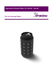
IV. D ESIGN
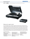
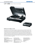
The hardware (Fig 1) consists of the following modules:
1) Actuation unit
2) Pneumatic control unit
3) Electronics unit
4) Computational unit
Out of the four units, only the actuator unit is specific
to the robot being driven by the system. Presently this unit
is configured for tendon driven hands. However, it should
Computational Unit
Electronics Unit
Power
Pressure
Pressure
Sensor
Sensor
Pressure
Remote
controller
Chassis
E-Stop
Breakout
Sensor
Length Pressure
Pressure
Sensor Sensor
Pressure
Sensor
Pressure
Length Sensor
Pressure
Sensor
Actuator
Sensor
Pressure
Length
Sensor
Length
Sensor
Sensor
Length
Actuator Unit
Sensor
Length
Sensor
Length
Sensor
Length
Actuator
Unit
Actuator
Sensor
Length
Actuator
Sensor
Actuator
Unit
Actuator
Sensor
Actuator
Actuator
Unit
Actuator
Actuator
Unit
Actuator Unit
Actuator Unit
Actuation Unit
Valves
Valve
Valve
Manifolds
3D Tracking System
other comparable choices. To be clear, there is no perfect valve
at the moment. Apart from the higher price, high quality valves
are large and must be mounted off-board. This alone is not an
issue (given that the compressor is also off-board), but offboard mounting means that there is an air line between the
valve and the cylinder, and the longer the line is the slower
the actuator becomes. However, for the combination of line
lengths, flow rates, pressures and cylinder volumes used here,
we were able to achieve maximum force in the cylinder around
10 msec after sending a command to the valve – which is faster
than the response of human hand muscles to neural input.
Another deviation from the ShadowHand design is that
we attached a linear magnetic sensor to each cylinder. Even
though the ShadowHand has a joint angle sensor in each dof,
we reasoned that sensing the cylinder positions directly is
useful for avoiding tendon slack and also calibrating the tendon
moment arms; and that other hands may not have joint angle
sensors – indeed we have already built an alternative hand
(UW Hand [5]) which falls in the latter category. Overall,
our philosophy was to design and build the best-performing
actuation system we could afford (on a budget of $60,000).
This includes a National Instruments PXI systems allowing us
to sample 48 pressure sensors at 32KHz and 48 linear position
sensors at 9KHz and average within batches, resulting in very
low noise measurements. Later in this paper we discuss options
for building a less expensive system with similar performance.
Pneumatic
E-Stop
Air
Filter
Compressor
Air Preparation Unit
Pneumatic Control Unit
Fig. 1.
Hardware design schematics. Air pathway is represented using
blue lines. Electrical pathway is represented using purple lines. Digital data
pathway is represented using pink lines.
be noted that the actuator units bear no restriction towards
tendon driven systems. All actuation mechanisms (tendon
driven/ direct actuation) under all configurations (single/double
acting, bundled/ distributed) are supported. The last three
modules can be used for any pneumatically actuated system
with appropriate configuration of the actuator unit.
V. ACTUATION UNIT
Presently, the actuation unit is configured as a tendon driven
hand, thus we call it ’Muscle Actuation Unit’. It consists of
the following sub-modules
1) Hand muscles actuation unit
2) Arm muscles actuation unit
In addition to the above, the muscle actuation unit houses
two components of electronic units - the pressure and length
sensor. These are discussed in detail in section VII.
Muscles acting over the finger and wrist tendons form ‘hand
muscle actuation unit’ . It consists of Actuator units, and
Housing assembly. Muscles acting over the lower arm, elbow,
upper arm and shoulder form ‘Arm muscles actuation unit’.
A. Actuator unit
Design parameters: The selection of actuators was based
on the design parameters listed below in decreasing order of
priority.
1) Minimum friction and stiction
2) Maximum force output
3) Fast with minimum response time
4) Minimum weight of actuators
5) Compactness of actuator unit
6) Compatibility with sensory devices
7) Availability in different configurations for different use
cases
8) Durability
It should be noted that these principles focus on generic
actuation mechanisms. No restrictions specific to tendondriven systems were made.
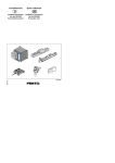
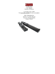
Hardware details: The actuator unit (Figure:2) consists
of double-acting Airpel series cylinders commercially manufactured by Airport Corporation. Single-acting cylinders are
often air-return or spring-return and do not allow control over
the return force. Double-acting cylinders were selected for
complete control over the actuation force in both directions
(although this feature is not yet utilized). The finger tendon’s
actuator unit has stroke length of 37.5mm, can produce up
to 42N of force and weights 45.7grams. The wrist tendon’s
actuator unit has stroke length of 50mm, can produce up to
125N of force and weights 95.7grams. Detailed specifications
can be found at [6].
Double-acting modules were used in single-acting mode
in the Muscle Actuation Unit. Finger tendons were actuated
using M9 cylinders and wrist tendons were actuated using M16
cylinders. In tendon driven systems, it seems preferable to have
a small force on the actuators to avoid tendon slack when
the muscles are in passive non-pulling state. However, the
non-zero force from the passive tendon creates co-contraction
and adds undesirable stiffness to the joints. The return force
of single acting cylinders are fixed and non observable and
cannot be compensated using pneumatic forces since both
forces act in same direction. Double-acting cylinders with no
return were employed to simulate virtual variable stiffness
springs to intelligently handle tendon slack and minimize joint
co-contraction. Variable stiffness simulated springs facilitated
control over the return force which would not have been
possible if single acting cylinders were used. For compatibility
with length sensors, magnetic cylinder pistons were used.
B. Housing assembly
Design parameters: The design parameters for the housing
assembly are listed below in decreasing order of priority:
1) Strength, load bearing and stability
2) Minimum off-axis actuator loads
3) Compactness of Hand muscles actuation unit
4) Weight
5) Ventilation
6) Compatibility with different hands
7) Ease of component assembly
8) Machinability
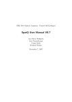
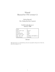
Hardware details: Figure: 3 shows the final housing assembly without the actuator unit. The assembly contains 36
of the M9 Airpel actuator units for finger tendons, and 4 of
the M16 Airpel actuator units for wrist tendons.
Tendon-driven robotic hands usually route finger tendons
via the center of wrist joint in order to minimize the moment
arms of finger tendons on the wrist joint. As a result, all finger
tendons come out of the hand via an opening at the wrist. To
reduce off-axis actuator loads, it is desirable to mount the
cylinders so that they all point to this opening – suggesting
a concave mounting plate. The back plate is free of cables
and connectors and has mounting holes for attachment to a
robot arm. It is compatible with the Shadow Arm robot –
which we have also redesigned with air cylinders, but this
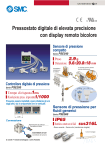
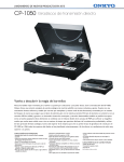
will be described elsewhere. Figure: 4 shows the complete
Muscle actuation unit without the back plate. Note that if we
did not attach a length sensor to each cylinder (which doubles
the cylinder diameter) the diameter of the assembly could be
reduced roughly by half.
Fig. 2. Cylinder unit [AC: Actuator, LS: Length Sensor, PS: Pressure Sensor]
Design evaluation and experience: The actuator selection
was the most critical and challenging selection of the entire
design. More than 16 models from 6 different manufacturers
were rigorously tested over the listed design parameters.
Though all the considered models performed well on most
deign parameters, requirements 1 and 3 were exceptionally
severe.
The models from Airpel significantly outperformed others
on criteria 1 and 3. The stiction and friction values for these
models were exceptionally small - the piston fell under its
own weight when the cylinder was not horizontal. This is
possible because the traditional pneumatic seals have been
replaced with “air seals” with precision-fit graphite pistons that
slide freely (without lubrication) inside a Pyrex glass cylinder
providing unique ability to impart smooth motion at very low
pressures, slow speeds and short strokes. There is a small air
leak of about 2SL/min [7], however this is not an issue when
using high flow rate valves.
To sum up, the Airpel cylinder we selected rates well on all
parameters except 4 and 5, on which it rates moderately.
(a)
Fig. 3.
(b)
Housing assembly (a) CAD model (b) Final machined assembly
Design evaluation: Machining the housing assembly (and in
particular the curved plate) turned out to be harder than it first
appeared, but was eventually successful. It weighs 660grams,
and can sustain about 75N from each actuator with a factor
of safety 3. When the actuators and the ShadowHand are
mounted, the entire system weighs 4.5kg. When attached to
a robot arm, most of this mass is near the base (elbow), thus
we do not expect it to be problematic.
VI. P NEUMATIC CONTROL UNIT
Design Parameters: For the pneumatic control unit, the
following design parameters (in decreasing order of priority)
(a)
(b)
Fig. 4. Muscle Actuation Unit (a) CAD model (b) Final assembly (without
back plate). [FP: Front Plate, HM: Hand Mount, LS: Length Sensor, AC:
Actuator, PS: Pressure Sensor, PC: Pneumatic Connectors]
were established.
1) High flow rate
2) High update frequency
3) Minimum pneumatic latency
4) Minimum pneumatic bottlenecks and avoid air pockets
5) Independent of type of actuation unit
6) Modularity
7) Facilitate modification and accommodate extension
8) Compact and light weight
9) Cost
Fig. 5. Pneumatic Control Unit (2ft x 2ft x 2ft) [CH: To chassis, BP: Breakout
Panel, CB: Circuit Breaker, PE: Pneumatic E-stop, AF: Air Filter, MF: Air
Manifold, HD: Hand, PC: Pneumatic Connections, HM: Hand Mount, HA:
Hand muscle actuation unit, VL: Valve, ES: E-Stop, CM: To Compressor,
PW: Power]
Hardware details: The pneumatic control unit (Fig 5)
consists of the following subunits:
1) Air preparation module consists of air compressor and
LFR-3/4-D-5M-MAXI-A filter regulator with a flow rate
of 7,600L/min at 6 bar. Detailed Specifications can be
found in [8]
2) Pneumatic control Valves: Pneumatic control unit contains 40 MPYE 3/5 proportional valves from FESTO.
Pneumatic valves (MPYE-5-M5-010-B) used for ’Hand
muscle actuation unit’ have a flow rate of 100l/min at
6bar, bandwidth of 125Hz and weight 290g. Detailed
specifications can be found at [8].
3) Air supply manifolds: MPYE series proportional valves
were designed by FESTO as stand alone, high end devices
to be used as individual units. Thus no manifold solution
have been made available for these valves. After careful
examination, PAL manifolds of TIGER-2000 series [8]
valves were modified for compatibility with MPYE series valves. Pneumatic control unit contains 5 PAL-10-B
manifolds [8], each serving 10 pneumatic control valves.
Evaluation and Experience: Proportional valves were preferred over binary switching valves despite their moderate
performance on parameters 8 and 9. This was driven primarily
by our application requirement that called for fine-grained
control over flow rate for fast and precise actuator control.
Binary switching valves achieve variable flow rates using
pulse width modulation (PWM) which restricts smooth and
precise control over flow rates. Moreover, PWM frequency is
limited by the bandwidth of the device, further constraining
smooth behaviours. A bank of binary valves can get very loud
when switching at a fast rate.
PAL manifolds are capable of serving valves with flow
rates up to 2600l/min i.e. our manifold solution is capable
of facilitating upgrades to all MPYE series models without
any modification. High flow rate (20X the requirement of
the presently used MPYE-5-M5-010-B model) manifolds are
preferred since they act as pneumatic buffers, thus avoiding
air pockets under heavy flow requirements. Our air supply
manifold presently contains 2 expansion slots. Addition of
manifolds for future expansion is facilitated by the high level
of modularity in the design, within reasonable efforts.
Pneumatic latencies are a function of tube lengths between
the actuators and the valves. The air path between them was
minimized to the extent possible. Pneumatic manifolds and
valves were configured to minimize the pneumatic interface
(face where valves expose their pneumatic connections to actuators) surface area, thus minimising the tube length between
valves and respective actuators.
VII. E LECTRONICS UNIT
The electronics unit consists of the followings components:
1) Sensors: Cylinder pressure sensors, and piston length
sensors (housed by ’Muscle actuation unit’ Figure:2).
2) NI PXI Chassis with multiple A/D and D/A boards.
3) Power Supply.
4) Emergency Stop.
Design parameters:
1) Sensors
a) Observability of entire state of the system
b) Resolution, bandwidth and range
c) Compatibility with generic pneumatic actuators
d) Stand alone, compact and light weight
e) Flexibility and ease of replacement
2) Chassis
a) Minimum latency
b) Sensing resolution, bandwidth and range
c) Data bandwidth for communication with computational
unit.
d) Support for multiple communication protocols
e) Expandable and reconfigurable
f) Support for different operating systems
g) Compact, enclosed and safe
3) Power Supply
a) Compatible with sensor and actuator requirements
b) Clean and reliable
c) Peak load capacity
d) Electromagnetically decoupled output channels
e) Overload protection, over voltage protection and shortcircuit protection
f) Indication monitor
4) Emergency Stop
a) Minimum latency
b) User and hardware safety
Hardware details:
1) Sensors
a) Pressure Electronics unit contains 48 solid state SMC
pressure sensor. 40 sensors are housed by ’Hand muscle actuation unit’ and rest 8 by ’Arm muscle actuation
unit’.
b) Length Electronics unit contains 48 Sick magnetic
piston length sensor. 40 sensors are housed by ’Hand
muscle actuation unit’ and rest 8 by ’Arm muscle
actuation unit’.
c) 3D-tracking system consists of active marker motion
tracking system from PhaseSpace. [9]
2) Chassis: National Instrument’s 9-Slot 3U PXI Express:
PXIe-1078 module with 1GB/s is configured as Chassis.
Each slot has a bandwidth of 250MB/s. Present configuration of modules sample 40 hand length sensors
at 9kHz and 48 pressure and 8 arm length sensors
at 32kHz. Chassis is also equipped with 1mbps CAN
module which is used to communicate with ShadowHand
sensors. Computational unit uses one 798MB/s bandwidth
PXIe-PCIe data channel for complete control over the
chassis. Detailed specifications can be found at [10]
3) Power Supply: 24 V DC 10Amps S8VS-24024A switching
power supply from OMRON [11] is used as power source.
One electromagnetically separated channel powers the
sensors while the other powers the Pneumatic control
valves.
4) Emergency Stop: A hybrid combination of software and
pneumatic e-stop is used as an Emergency unit. Pneumatic stop has a flow rate of 6,500 l/min at 6 bar and
weighs 600gms.
Design evaluation and experiences:
TABLE I
S ENSOR S PECIFICATIONS
Specifications
Measuring Range
Operational Voltage
Analog output
Resolution
Linearity
Repeatability
Sample Time
Current consumption
Output impedance
Weight
Max Speed
PSE540(A) [12]
0-1Mpa
12-24
VDC,
ripple(P-P) ±10%
1-5 VDC
<2%
<±0.7%
<±0.2%
N/A
<15mA
1kΩ
4.6g(without wires)
N/A
MPS [13]
32-256mm
15-30
VDC,
ripple(P-P) ±10%
0-10 VDC
0.05mm
0.3mm
0.1mm
1 ms
25mA
2kΩ
N/A
3m/s
Since the intended applications of our system was towards
research applications, there was never a preference towards
onboard electronics.
Designing onboard electronics can definitely make the
overall system compact and independent. These advantages
from design of onboard electronics would have come at the
cost of reconfigurability and extendability of the hardware.
Furthermore, it would have conflicted with our overall design
parameter-4 of using off-the shelf components to the extent
possible. All connections were made using TBX-68, a DIN
rail mount screw terminal connector block from NI, for
accessability, reconfigurability and debugging purposes.
1) Sensors
a) Pressure: Air path adds latency to any pneumatic
system. Since our actuators are driven using off-site
high flow valves, pressure sensors were placed closest
possible to the actuators to account for the pneumatic
latency.
b) Length: Length sensing capability was a difficult
choice, as it posed several challenges at multiple levels. Piston length sensing capabilities were added to
cater to some of our recent efforts in the direction
of bio-mimetic tendon driven systems [14] [15]. In
such systems, it is particularity difficult to have joint
angle sensors. Access to tendon excursions helps with
kinematic modeling [15].
Size of Actuator unit: The size of the actuation unit
had to be increased to accommodate for length sensing
without which the diameter of the hand muscle actuation unit would have been comparable to the typical
dimensions of a human forearm.
Number of Analog Input channels: Due to high
impedance of length sensors we observed ghosting [16]
[17]. In case of ghosting, every sensor at ith channel
of DAQ gets coupled with the one connected to every
(i+1)th channel. Most acceptable and efficient way to
eradicate ghosting is to interleave null/ground channels
between each sensor channels. Null channel interleaving completely eliminated ghosting but resulted in 2X
number of DAQ channels.
2) Chassis: 2X AI channels were used for length sensors
to mitigate the effects of ghosting. This requirement was
met by replacing one PXIe6363 module with PXIe6255
module that has more number of channels but a lower
sampling frequency. This reduced the rate at which
Hand actuation unit’s length sensor can be sampled from
32KHz to 9Khz.
3) Power supply: Power is distributed via modular power
strips. Individual sensors/actuation banks can be turned
on/off to minimize noise floor and system load when not
in use. Modular power distribution facilitates addition of
different power supply units for individual sensor/actuator
submodules, thus facilitating upgrades at all levels.
4) Emergency Stop: Control valves provide unreliable flow
rates when pneumatic input is fed without operating
power. Unreliable flow rates can damage the robot by
pushing it outside its stability regime or setting joints
into oscillations. Emergency module was designed to
allows pneumatic flow input only when control valves
are powered up.
Initially, we considered a complete shutdown in case of
operational emergency e.g. robot performing an undesirable movement. However, careful observations (listed
below) revealed that powering down the pneumatics is a
more reliable and faster option.
• Valve charging up its actuator’s pressure when emergency was triggered: Due to pneumatic buffers feeding the control valves, the actuator will continue
charging up till the pressure drops in the buffers and
then actuator’s residual pressure flushes out.
• Actuator is pressurized and valve is closed to maintain the chamber pressure when emergency is triggered: This pressure gets trapped in the cylinder and
emergency not avoided.
The correct way to process an operational emergency is to
exhaust the input pressure by flushing out the pneumatic
buffers (using a high flow exhaust port) and opening the
valves to exhaust out the cylinder pressure. This requires
a pneumatic shutdown while valves maintain their input
operating power. For a non operational emergency, circuit
breakers are provided at all levels from top, which powers
down the entire system, to bottom level, which powers
down individual subcomponents.
VIII. C OMPUTATIONAL U NIT
Design parameters: Design parameters established for the
computational unit have been listed below in decreasing order
of priority
1) Reliable communication
2) Minimum communication latency
3) Maximum computational capacity
4) Maximum data bandwidth
Hardware details: NI PXIe-PCIe8371, x4 MXI-Express is
used to communicate with the chassis using a high bandwidth
PCI Express link. Any normal desktop or server computer with
PCI express slot can serve as a Computational unit. 3D motion
tracking system communicates using a standard ethernet port.
PCIe link is used to retrieve pressure sensor and length sensor
data, and to command the Pneumatic control assembly.
Design evaluation and experiences: Data communication
using PCIe link and standard ethernet link ensured that our
system is compatible with any standard computer without any
special requirements. Presently a 3.0Ghz AMD Phenom(tm) II
X6 1075T, 8.00 GB machine with Win7 OS is used to control
the system.
IX. D ESIGN E VALUATION
Final hardware was evaluated on various design parameters
using two tendon driven hands. Actuation system was perfectly
compatible with both hand designs without modification.
1) 24-dof ShadowHand, developed by ShadowHand company [1]
2) 20-dof UW hand, being developed at our lab independent
of the actuation system [5]
(a)
(b)
(c)
Fig. 6. (a) ShadowHand mounted on the actuation unit. (b) UW hand [5]
mounted on the actuation unit (c) ShadowHand finger dimensions
A. Force and compliance
System force and compliance characteristics were studied
using the ShadowHand and UW Hand. An external force
of 6 grams for ShadowHand (and 8gms for UW Hand) at
the index finger tip was enough to flex the MCP joint thus
confirming the exceptional compliance of the final system.
Typical characteristic force behaviours are summarized in
Table II & III
TABLE II
ACTUATOR FORCE CHARACTERISTICS
Specification: No load connected
to piston
Minimum external force to break
stiction and friction
Minimum external force to break
stiction and friction
Orientation
Force
Horizontal
2.5g
vertical
Piston falls under
its own weight
TABLE III
H AND FORCE CHARACTERISTICS
Specification: Finger and actuators oriented vertically
Shadow UW
Hand
Hand
4.0g
2.0g
Minimum actuation force at finger tip to move MCP
joint (at atm pressure)
Minimum actuation force at finger tip to move MCP
joint (at min slack correction pressure)
Maximum flexing force at Index finger tip
Maximum extension force at Index finger tip
Pressure(PSI)
60
30
8.0g
300.5g
439.4g
705g
700g
V=5.0
V=4.8
V=4.6
V=4.4
V=4.0
V=3.4
V=2.2
90
Pressure(PSI)
V=5.0
V=5.2
V=5.4
V=5.6
V=6.0
V=6.6
V=7.8
90
6.0g
60
D. video attachment
A supplementary video is attached with the manuscript. The
video demonstrates speed, reflex and compliance properties
of the actuation system with ShadowHand skeleton. Speed
behaviour is demonstrated using a sequence of flection and
extension of joints (limit to limit), one at a time. Entire
sequence of flexing and extension for all 24 joints merely takes
2.44 seconds. Each movement is roughly 70 milliseconds.
Hand reflex is demonstrated using the experiment mentioned in
subsection above. System compliance is demonstrated using 3
experiments. First, we demonstrate that actuation yields away
to air blow from an average adult. Second, dead weights of
1g, 2g and 5g were dropped on the finger from a height of
5 cms to show compliance. Third, we demonstrate the effects
of gentle interactions from an average adult.
30
1
0
Index MCP Extensor Pressure
Middle MCP Joint velocity (Purturbation)
Index MCP Joint velocity (Reflex)
0
0
30
60
Time(ms)
(a)
90
0
30
60
90
Time(ms)
(b)
Fig. 7. (a) Pressure behaviours while pressuring cylinder from zero using
valve command(V) (b)Pressure behaviours while exhausting cylinder from
zero using valve command(V)
B. Actuation Speed
Our prime motivation for the development of this actuation
system was to use tendon-driven hands and perform dexterous
hand manipulation experiments. Any dexterous hand manipulation demands agility and responsiveness from its actuation
hardware. These capabilities are evaluated in the present and
the following section. The actuation system’s speed capabilities were evaluated using a simple open loop bang-bang
control strategy over the index finger MCP joint. The goal
was to achieve full stroke movements (joint limit to joint
limit) at maximum frequency. Control switching frequency
was gradually increased until finger started making incomplete
strokes, i.e. reversed before hitting the joint limits. Using this
simple strategy, a frequency of about 7Hz was achieved. We
are working towards a more principled way to further improve
actuation speed by carefully modelling valve and pneumatics
of our system. Further details are provided in [18]
C. System latency and event timings
System responsiveness was evaluated using a reflex experiment. During the experiment, small external disturbances were
applied at the finger tip of the middle finger. The system was
programmed to detect the disturbance (using the joint angle
sensors in the ShadowHand) and react by extending the index
finger. The system was found capable of detecting minute disturbances and reacting very quickly. One can consider multiple
definitions of response latency. The first change in pressure
is observed 8 msec after the disturbance (this corresponds
to reflex latencies defined in terms of muscle activity in the
biological motor control literature). See Fig 8. When measured
in terms of the resulting motion, the latency is around 29 msec.
0.5
0
0
20
40
60
Time(ms)
Fig. 8. Time stamps(from left to right): T 1(Event Trigger, Middle finger
MCP movement detection) = 18.179ms, T 2(Actuation voltage written to
valve) = 22.084ms, T 3(Pressure wave arrival) = 24.044ms, T 4(Index finger
MCP movement detected) = 46.943ms, T 5(maximum pressure at the actuator)
= 47.55.
X. H OW TO MAKE THE SYSTEM LESS EXPENSIVE
The approximate cost breakdown of our present system is
as follows:
Component
FESTO valves
SICK sensors
AirPel cylinders
Pressure sensors
NI PXI system
Custom machining
Unit price
$800
$250
$50
$50
Total
$32,000
$10,000
$2,000
$2,000
$10,000
$4,000
The most expensive components (and thus primary candidates for simplification) are the valves, linear sensors, and
electronics. The PXI system we configured is an overkill,
considering that the sensors have low noise to start with (so the
high sampling rates and mini-batch averaging are not essential)
and the bandwidth of the valves is only 125 Hz so there is
no point in having a fast control loop (indeed we are only
using 200 Hz). The National Instruments system has very
mature drivers and is overall a great choice, but one could
build a considerably less expensive replacement for the present
purposes, perhaps using multi-channel A/D chips on custom
circuit boards mounted in the forearm.
The biggest potential for savings are in the valves and
position sensors. Presently we use one valve and one sensor
per cylinder. This results in a universal pneumatic drive which
can be used to actuate any mechanism with up to 40 tendons.
Note however that 40 is actually quite a lot, and is only
needed when using so-called 2N designs where tendons act
on individual joints and are arranged in agonist-antagonist
pairs (as opposed to the more distributed action found in
the human hand and in the ACT hand). If we are willing
to assume that most or all tendons will always operate in
agonist-antagonist pairs, we could use one valve and one
position sensor per tendon/cylinder pair (note that we still
need all cylinders because even in this organization the two
tendons in a pair will typically have different and possibly
variable moment arms). The FESTO MPYE valves are 5/3
valves and are in fact designed to power pairs of cylinders.
With these simplifications, the cost can be reduced by half.
The ShadowHand skeleton (without any actuation) still costs
around $60,000. However, as shown in our companion paper
[5], one can 3D-print a hand with comparable dexterity with
cost of materials around $100 and a couple of days of assembly
work. Combining these two advances, it should be possible to
make dexterous robotic hands whose performance exceeds any
product available on the market to today, for less than $40,000.
These hands rely on off-the-shelf components and 3D printing,
and could be built in academic labs.
Finally, we are not certain that proportional valves are
actually needed. We clearly need valves that respond quickly
and have high flow rates, but what if they were binary (and thus
presumably a lot cheaper)? In principle proportional valves
provide smoother movement, but given that air dynamics
introduce low-pass filtering, it remains to be seen how much
the performance of the (to-be-developed) control schemes will
degrade in the presence of binary valves. If the degradation
turns out to be negligible, this will result in substantial further
reduction in the cost of the robotic hands we envision.
XI. S UMMARY
The development of the present system was motivated by
our desire to solve complex dexterous manipulation problems.
We emphasize that we are not building hardware for the sake
of building hardware. Indeed the primary focus of our research
group is control; see [19] [20] [21] for examples of recentlydeveloped control schemes applicable to complex robots. If the
robotic hardware we need already existed, we would be more
than happy to focus on using it and making progress in terms
of control. Unfortunately suitable hardware in terms of robotic
hands does not appear to exist (with the possible exception of
the DLR hand which is not available commercially), and so
we were forced to develop the system described here. This
development is now complete and we are ready to make a
transition to control experiments. We are also finalizing the
re-design of the ShadowArm robot with similar actuation, and
will soon be able to mount the hand assembly on the new
arm. Once the entire system is functional and used in specific
manipulation experiments, we will be able to characterize its
capabilities in context. But the basic tests performed here
already illustrate that the system is very capable.
We hope that other research groups as well as commercial
entities will be interested in building similar actuation systems.
This paper contains a lot of technical details that should help
in replication efforts, and we are happy to provide additional
details upon request.
XII. ACKNOWLEDGEMENTS
This work was supported by the US National Institutes of
Health and the US National Science Foundation. Thanks to
Alex Simpkins and Rob Mabery for their help with the design
and machining.
R EFERENCES
[1] Shadow Robot Company, www.shadowrobot.com.
[2] S. Jacobsen, E. Iversen, D. Knutti, R. Johnson, and K. Biggers, “Design
of the utah/m.i.t. dextrous hand,” in Robotics and Automation. Proceedings. 1986 IEEE International Conference on, vol. 3, apr 1986.
[3] A. Deshpande, Z. Xu, M. Weghe, L. Chang, B. Brown, D. Wilkinson,
S. Bidic, and Y. Matsuoka, “Mechanisms of the anatomically correct
testbed (act) hand,” IEEE/ASME Trasactions on Mechatronics, 2011.
[4] E. Chao, J. Opgrande, and F. Axmear, “Three-dimensional force analysis of finger joints in selected isometric hand functions,” Journal of
Biomechanics, vol. 9, no. 6, pp. 387–396, 1976.
[5] X. Zhe, V. Kumar, and E. Todorov, “A low-cost, 20-dof anthropomorphic robotic hand: Design, actuation and modeling (manuscript under
review).”
[6] Airpel, http://www.airpot.com/html/airpels.html.
[7] Airpel AntiStiction, http://www.airpot.com/html/anti stiction.html.
[8] Festo Company, www.festo.com.
[9] PhaseSpace Company, www.phasespace.com.
[10] National Instruments Company, www.NI.com.
[11] Omron Company, http://www.omron.com.
[12] SMC Company, www.smcworld.com.
[13] SICK Company, www.sick.com.
[14] A. D. Deshpande, R. Balasubramanian, R. Lin, B. Dellon, and Y. Matsuoka, “Understanding variable moment arms for the index finger mcp
joints through the ACT hand,” in IEEE BIOROB, 2008.
[15] X. Zhe, V. Kumar, Y. Matsuoka, and E. Todorov, “Design of an
anthropomorphic robotic finger system with biomimetic artificial joints,”
in IEEE BIOROB, 2012.
[16] National Instruments Company, “Knowledgebase 3l8ietlo: How do i
eliminate ghosting from my measurements?”
[17] National Instruments, “X series user manual: Multichannel scanning
considerations.”
[18] T. Yuval, T. Wu, J. Movellan, and E. Todorov, “Modeling and identification of pneumatic actuators(manuscript under review).”
[19] I. Mordatch, Z. Popovic, and E. Todorov, “Contact-invariant optimization
for hand manipulation,” in Eurographics/ACM SIGGRAPH Symposium
on Computer Animation.
[20] Y. Tassa, T. Erez, and E. Todorov, “Synthesis and stabilization of
complex behaviors through online trajectory optimization.”
[21] E. Rombokas, M. Malhotra, E. Theodorou, E. Todorov, and Y. Matsuoka, “Tendon-driven variable impedance control using reinforcement
learning,” 2012.