1
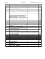
TEST REPORT
Luminaires
Part 1: General requirements and Tests
Part 2: Particular requirements Section 4: Portable general purpose luminaires
Report Reference No:
T1321-21-12
Tested by:
Urs Wyttenbach
Approved by:
Dr. F. Stucki
Date of issue:
09 July 2012
Number of pages:
31 pages
Testing Laboratory:
QUINEL AG
Address:
Grundstrasse 2
CH-6343 Rotkreuz
S
T
S
Schweizerischer Prüfstellendienst
Service Suisse d' essai
Servizio di prova in Svizzera
Swiss testing service
Testing location:
Rotkreuz
Applicant’s name:
OEE Odermatt Electronic Engineering, Mr Marco Odermatt
Address:
Steinersmatt 28, CH-6370 Stans
Manufacturer's name:
OEE Odermatt Electronic Engineering
Address:
Steinersmatt 28, CH-6370 Stans
STS 037
Test specification
Standards:
EN 60598-1:2008+A11:2009, EN 60598-2-4:97
IEC 60598-1:2008, IEC 60598-2-4:97
Test procedure:
Type testing
Deviation of standard or procedure:
none
luminaire under test
Description:
Portable floor lamp with infrared detector to be put under a bed
Trademark:
OEE
Model and/or type reference:
Luna
Rating(s):
230V, 50Hz, max. 53W, class II
Date of receipt of luminaire:
20 April 2012
Summary of testing:
passed
Copy of the type label
QUINEL
page 2 of 31
Report reference No: T1321-21-12
Test verdicts:
- test item does not apply to the tested object:
N
- test item meets the requirement:
P
- test item does not meet the requirement:
F
- test item not checked:
--
General remarks:
For the acceptance of the components see Table 1 "Safety relevant components"
The test results presented in this Test Report relate only to the tested luminaire(s).
This Test Report has to be read together with the standards.
This Test Report shall not be reproduced except in full.
Remarks:
The electronic part (on PCB) has been tested by simulating possible fauts following EN 61347-1.
The enclosure is mounted with pins and then glued.
For the assessment and tests used documents provided by the applicant or
manufacturer
- Montageanleitung / Assembly Instructions by the manufacturer
- Certificates and specification of components and plastic enclosure (see Table "Safety relevant
components")
- Circuit diagram of electronic circuit
- Lay-out of PCB
QUINEL
page 3 of 31
Report reference No: T1321-21-12
Clause
Requirement
2
CLASSIFICATION
2.2
Type of protection against electric shock:
class II
2.3
Degree of protection against ingress of water, dust
and solid objects:
IP20
2.4
Material of supporting surface:
2.5
Result / Remark
- Luminaires suitable for direct mounting on normally
flammable surfaces: No symbol required
yes
- Luminaires not suitable for direct mounting on
normally flammable surfaces: symbol required
no
Verdict
Circumstances for use:
- Luminaire for normal use: no symbol required
yes
- Luminaire for rough service: symbol required
no
Additional requirements for EN 60598-2-4
portable floor and table luminaires assigned to
luminaires for direct mounting on normally flammable
surfaces only
yes
3
MARKING (type label)
3.2
Mandatory markings
P
Position of the marking
P
Format of symbols/text
P
Mark of origin (trade mark, the manufacturer's
identification mark or the name of the responsible
vendor)
P
Rated voltage. For tungsten filament lamps only if the
rated voltage is different from 250V∼
P
Portable cl. III luminaires marked outside
N
3.2.3
ta if other than 25°C
N
3.2.4
Symbol for class II luminaires where applicable
P
portable class II luminaires with non detachable
flexible cord symbol outside
P
symbol not applied to semi-luminaires
N
3.2.5
Symbol for cl. III luminaires
N
3.2.6
IP numbers (IP20 on ordinary lum. not required)
N
3.2.7
Model number or type reference
P
3.2.8
Rated wattage or the designation as indicated on the
lamp data sheet of the type or types of lamp for which
the luminaire is designed
P
Where the lamp wattage alone is insufficient, the
number of lamps and the type shall also be given
N
Luminaires for tungsten filament lamps shall be
marked with the maximum rated wattage and number
of lamps
N
Where applicable, the relevant symbol for luminaires
not suitable for direct mounting on normally flammable
surfaces. See Table N.1
N
The symbol shall be explained on the luminaire or in
the manufacturer’s instructions provided with the
luminaire
N
The minimum size of the symbol shall be 25 mm for
each side
N
3.2.1
3.2.2
3.2.9
QUINEL
page 4 of 31
Report reference No: T1321-21-12
Clause
Requirement
3.2.10
Information concerning special lamps (e.g. high
pressure sodium lamps)
N
3.2.11
Symbol for luminaires for lamps of similar shape to
"cool beam" lamps but where the use of a dichroic
reflectorized "cool beam" lamp might impair safety
N
Except for type Z attachments, termination shall be
marked to identify live, neutral and earth in case of
connection of the luminaire to the supply mains to
ensure safe and satisfactory operation
N
3.2.12
Result / Remark
Verdict
Symbols, where applied, according to IEC 60417
P
Earthing terminal marked by symbol of IEC 60417 only
N
Leads (tails) used for the connection to extra low
voltage DC supply, shall be colour coded red for
positive termination and black for negative termination.
Fixed termination marked with "+" and "-" sign
N
Luminaires with non-detachable flexible cords without a
plug shall include with the manufacturer's instructions any
information necessary to ensure safe connection
N
3.2.13
Symbol for minimum distance from lighted objects on
the luminaire or in the instructions if necessary
N
3.2.14
Symbol for rough service luminaires if applicable
N
3.2.15
Symbol for bowl mirror lamps
N
3.2.16
"Replace any cracked protective shield" or symbol for
luminaires incorporating a glass protective shield
N
3.2.17
Max. number of luminaires that may be interconnected
or max. current that may be drawn by means of
couplers provided for looping-in connections to the
mains supply. For fixed luminaires alternatively within
the installation instructions
N
3.2.18
Warning symbol or notice for luminaires with ignitors
and double-ended high pressure discharge lamps and
luminaires with double-capped Fa8 tabular lamps if
voltage > 34 Vp
a) Warning symbol IEC 60417-5036 visible during
replacement of the lamp. Symbol explained on
luminaire or instructions, or
N
b) Warning notice near to the holder of a replaceable
ignitor: " Attention, remove...."
N
3.2.19
Symbol for luminaires which are designed for use with
self-shielded tungsten halogen lamps only
N
3.20
Where necessary, the means of adjustment where not
obvious, needs to be identified
N
3.21
The relevant symbol (see Figure 1) for luminaires not
suitable for covering with thermally insulated material.
The symbol shall be explained on the luminaire or in
the manufacturer’s instructions provided with the
luminaire. See Table N.1. The minimum size of the
symbol shall be 25 mm for each side
N
3.22
Symbol, if applicable, for luminaires with internal
replaceable fuses
N
3.3
Additional information:
Acceptable language of instructions
N
3.3.1
Combination luminaires
N
3.3.2
Nominal frequency in Hz
N
QUINEL
page 5 of 31
Report reference No: T1321-21-12
Clause
Requirement
3.3.3
Operating temperature Tw, Tc, insulation etc.
N
3.3.4
In case a luminaire is only suitable for direct mounting on
non-combustible surfaces and the relevant symbol is not
applied, a warning notice shall be attached to the luminaire
or given in the manufacturer’s instructions explaining that
the luminaire can under no circumstances be mounted on
normally flammable surfaces
N
3.3.5
Wiring diagram
N
3.3.6
Special conditions in case of looping-in
N
3.3.7
Metal halide lamp luminaire – warning about shield
N
3.3.8
Limitation for semi-luminaires
N
3.3.9
Power factor and supply current
N
3.3.10
Suitability for use "indoors"
N
13.3.11
Range of lamps if used with remote control gears
N
3.3.12
Clip-mounted luminaire – warning
N
3.3.13
Specifications of all protective shields
N
3.3.14
Symbol for nature of supply
N
3.3.15
Rated current of socket outlet
N
13.3.16
Rough service luminaire
N
3.3.17
Information about replacement of flexible cord in
mounting instruction for X, Y and Z attachment
3.3.18
Non-ordinary luminaires with PVC cable
N
3.3.19
Protective conductor current <10mA and permanent
connection protective current clearly stated in
manufacturer's instructions
N
Wall mounted and adjustable luminaires not intended to
be mounted within arms reach shall be provided with
information to advise their correct installation, i.e. “Only to
be installed outside arms reach”
N
3.3.101
terminal block not delivered with luminaire (tails)
N
3.4
Test with water
P
Test with hexane
P
Legible after test
P
Label attached
P
3.3.20
Result / Remark
type Z-attachment
Verdict
P
4
CONSTRUCTION
4.2
Components intended to be replaceable shall be so
designed that there is sufficient space to permit
replacement without difficulty and without impairing
safety
P
Wireways smooth and free from sharp edges, burrs,
flashes etc.
P
Metal set screws shall not protrude into wireways
P
4.3
4.4
Lampholders
4.4.1
Integral lampholder
N
4.4.2
Wiring connection of integral lampholders
N
4.4.3
Lampholder for end-to-end mounting
N
4.4.4
Positioning of lampholders
N
4.4.5
Peak pulse voltage of luminaires with ignitors
N
4.4.6
Centre contact of Edison lampholders
N
4.4.7
Rough service luminaires
N
QUINEL
page 6 of 31
Report reference No: T1321-21-12
Clause
Requirement
4.4.8
Lamp connectors
N
4.4.9
Caps or bases developed for ELV not permitted for
Urated > AC 50V
N
Luminaires intended for use with GU10 lamps only
(with aluminised reflector) shall be provided with GU10
lamp holders only.
N
4.5
4.6
Result / Remark
Verdict
Starter holders
Starter holders in luminaires other than class II shall
accept starters which comply with IEC 60155
N
For class II luminaires where the starter can be touched
with the test finger when the luminaire is fully assembled
or open for the replacement of lamps or starters, the
starter holder shall be one accepting only starters
complying with the requirements for starters for class II
luminaires given in IEC 60155
N
If provided with connecting leads (tails) requiring a
separate terminal block for the connection to the fixed
wiring, adequate space for this terminal block shall be
provided within the luminaire, or within a box delivered
with the luminaire, or specified by the manufacturer
N
4.7
Terminals and supply connections
4.7.1
In portable luminaires and in fixed luminaires that are
frequently adjusted, adequate precautions shall be
taken to prevent metal parts from becoming live due to
a detached wire or screw. This requirement applies to
all terminals (including supply terminals)
P
One of the following methods is deemed efficient to
prevent a wire form becoming detached:
4.7.2
4.7.3
a) wires are retained by a cord anchorage adjacent to
the terminals
P
b) conductor is clamped by a spring type screwless
terminal
N
c) the wire conductor is anchored to the tag before
soldering, unless breakage close to the soldering
place is likely to occur as a result of vibration
N
d) wires are twisted together in a reliable manner
N
e) wires are fastened together by insulation tape,
sleeves, or the like
N
f) the wire conductor is inserted into a hole in a printed
board, bent and soldered, the hole having a diameter
slightly greater than the conductor
N
g) the wire conductor is securely wrapped around the
terminal by means of a special tool
N
h) the wire conductor is crimped to the terminal by
means of a special tool
N
i) insulating lining in the enclosure
N
j) enclosure of insulating material
P
k) other method(s):
N
Supply terminals shall be located or shielded in such a Inspection and test
way that, if a wire of a stranded conductor escapes
from a terminal when the conductors are fitted, there is
no risk of contact between live parts and metal parts
which can be touched with the standard test finger.
Inspection and "8mm-test"
P
Terminals for supply conductors
P
QUINEL
page 7 of 31
Clause
Requirement
4.7.3.1
Welding method and material
Report reference No: T1321-21-12
Result / Remark
Verdict
Conductor stranded or solid wire of copper. For thin
wires, a ferrule may be used
N
Spot welding only (other methods under consideration)
N
Welding of wire and plate is allowed, but welding of
wires together is not allowed
N
Welded connections in type Z attachments only
N
Welding connections shall withstand mechanical,
electrical and thermal tests:
a) mech. test. 15.8.2 (if cord anchorage, no test required)
N
b) electrical test: 15.9
N
c) heat test: 15.9.2.3 and 15.9.2.4
N
Terminals, other than those for supply connection,
which are not covered by separate standards for
components, shall comply with the requirements of
sections 14 and 15
N
Terminals for lampholders, switches and similar parts
used for multiple connection of internal wiring shall
have dimensions adequate for the purpose and shall
not be used for the connection of external wiring
N
If the external wiring or supply cable is unsuitable for
the temperatures reached inside the luminaire, either
a connection shall be provided at the point of entry of
the external wiring into the luminaire for the use of
heat-resistant wiring after this point, or heat-resisting
parts shall be supplied with the luminaire to cover the
part of the wiring placed inside it, which exceeds the
wiring temperature limit. See also 12.4.2c). Max. 120°C
N
4.7.6
Multi-pole plug: unsafe connections, e.g. by shifting
the plug position, shall be prevented
N
4.8
Switches:
4.7.4
4.7.5
- adequate rated
N
- adequate fixing, secured against rotation and
removing by hand
N
- switches in flexible cables or cords and switched
lampholders shall not be used in luminaires other
than ordinary, unless the degree of protection against
dust, solid objects or moisture of the switch is in
accordance with the classification of the luminaire
N
- polarized supply, wired into the live side
N
- Electronic switches, when incorporated or supplied
with the luminaire shall comply with the requirements
of EN 61058-1
N
4.9
Insulating lining and sleeves
4.9.1
Reliably retained in position
N
4.9.2
Insulated linings, sleeves and similar parts shall have
adequate mechanical, electrical and thermal strength
N
Compliance according to manufacturer's specifications
N
Inspection and manual tests
N
Electric strength test
N
Insulation resistance and electric strength measured
after ageing test. Temperature (°C):
N
QUINEL
page 8 of 31
Report reference No: T1321-21-12
Clause
Requirement
4.10
Double and reinforced insulation
4.10.1
For metal encased luminaires, contact between:
- mounting surfaces and parts with basic insulation
only, and
- accessible metal parts and basic insulation,
shall be effectively prevented. (Applicable for internal,
external and fixed wiring of installation)
N
Class II fixed luminaires shall be so designed that the
required degree of protection against electric shock is
not impaired as a result of the installation of the
luminaire
N
No capacitors between live parts and body of metal
encased class II luminaires (exception next line)
N
Interference suppression capacitors according to
EN 60384-14 and method of connection in accordance
with EN 60065, 8.6/14.2.1b)
N
Any assembly gap with a width greater than 0.3mm in
supplementary insulation shall not be coincidental with
any such gap in basic insulation, nor shall any such
gap in reinforced insulation give straight access to live
parts
N
Openings in double or in reinforced insulation shall not
give straight access to live parts, so that the live parts
can be touched with the conical pin of test probe 13,
Figure 9 of IEC 611032
N
Parts which serve as supplementary or reinforced
insulation shall either be fixed or they shall be unable
to be replaced in an incorrect position
N
Where sleeving is used as supplementary insulation
on internal wiring, and where insulated linings are
used in lampholders as supplementary insulation on
external or internal wiring, the sleeving and lining shall
be retained in position by positive means
N
4.10.2
4.10.3
4.11
Electrical connections and current-carrying parts
4.11.1
Contact pressure not transmitted through insulating
material, unless there is sufficient resilience in the
metallic parts to compensate for any possible
shrinkage of the insulating material
4.11.2
4.11.3
Result / Remark
Verdict
P
Screws:
Self-tapping screws shall not be used for the
connection of current carrying parts, unless they
clamp these parts directly in contact with each other,
and are provided with a suitable means of locking
N
Self-tapping screws may be used to provide earth
continuity, if it is not necessary to disturb the
connection in normal use, and at least two screws are
used for each connection
N
Thread-cutting screws shall not be used for the
interconnection of current-carrying parts of metal
which is soft or liable to creep, such as zinc or alu
N
Screws and rivets which serve as electrical as well as
mechanical connections shall be locked against
loosening. Spring washers may provide satisfactory
locking. For rivets, a non-circular shank or an
appropriate notch may be sufficient
N
QUINEL
page 9 of 31
Report reference No: T1321-21-12
Clause
Requirement
Result / Remark
4.11.4
Current-carrying parts shall be of copper, an alloy
containing at least 50% copper, or a material having at
lest equivalent characteristics, e.g. aluminium
P
Current-carrying parts shall be resistant to, or
adequately protected against, corrosion
P
4.11.5
Current-carrying parts shall not be in direct contact
with the mounting surface or wood
P
4.11.6
Electro-mechanical contact systems
N
4.12
Screws and mechanical connections and glands
4.12.1
Withstand mechanical stress in normal use, if safety
relevant
luminaire is glued
Verdict
N
Screws not made of a material which is soft or liable to
creep as zinc, some grades of aluminium and several
thermoplastics
N
Screws which are operated for maintenance purposes
shall not be of insulating material if their replacement
by a metal screw could impair supplementary or
reinforced insulation
N
Torque tests
N
4.12.2
Screws transmitting contact pressure and < 3 mmØ
shall screw into metal
4.12.4
Screwed and other fixed connections between
different parts of luminaires shall be made in such a
way that they do not work loose through such torsion,
bending stresses, vibration, etc., as may occur in
normal use. Fixed arms and suspension tubes shall be
securely attached; e.g. soldering, welding, lock nuts,
set screws
N
Compliance torque test
N
Test: Lampholder; torque (Nm):
approved terminal block
glued
P
N
Test: Push-button switches; torque 0.8 Nm
N
4.12.5
Test: Screwed glands:
N
4.13
Mechanical strength
4.13.1
Luminaires shall have adequate mechanical strength
and be so constructed as to be safe after such rough
handling as may be expected in normal use
P
Impact tests
see Table 4.13.1
4.13.2
Metal parts enclosing live parts shall have adequate
mechanical strength
at least basic insulation
4.13.3
Test with unjointed straight test finger:
4.13.4
4.13.6
P
N
- During the test, metal parts shall not touch live parts
N
- After the test, covers shall not be excessively
deformed and the luminaire shall continue to meet
the requirements of section 11
N
Rough service luminaires shall have protection against
ingress of solid objects and moisture of at least IP54
N
a) fixed
N
b) hand-held
N
c) delivered with a stand
N
d) for temporary installations and suitable for mounting
on a stand
N
Tumbling barrel test for plug-ballast/transformer and
mains socket-outlet-mounted luminaires
N
QUINEL
page 10 of 31
Report reference No: T1321-21-12
Clause
Requirement
4.14
Suspensions and means of adjustment
4.14.1
Mechanical suspension shall have adequate factors of safety:
4.14.2
Result / Remark
Verdict
Test A for suspended luminaires: four times the weight
added
N
Test B for rigid suspension luminaires: torque 2.5 Nm
N
Test C for rigid suspension brackets
N
Test D for track-mounted luminaires
N
Test E for clip-mounted luminaires
N
Manufacturer provides guidance and/or means for
safe installation and use
N
Load to flexible cables or cords of luminaires suspended by flexible cable or cords
Mass of the luminaire suspended by flexible cords
shall not exceed 5kg
N
Stress in conductors shall not exceed 15N/mm²
N
Where a luminaire >5kg, so suspended that no tension
to conductors
N
Semi-luminaires: mass and bending moment
N
a)Adjusting devices (joints, hoisting devices, adjusting
brackets, telescopic tubes etc) shall be so
constructed that cords or cables are not pressed,
clamped, damaged or twisted along the longitudinal
axis by more than 360° during operation
N
- flexing test; number of cycles (1500/150/45):
N
- not more than 50% of the strands broken, no serious
damage to the insulation
N
- electric strength test afterwards
N
b) Luminaires....shall allow the operation of its intended
function without impairing the stability of the luminaire
or causing deformation of any part of the construction,
nor cause injury due to temperatures above those
specified in Table 12.1.
N
c) For luminaires....shall comply with the temperature
limits for the means of adjustment, as specified in
Table 12.1. The same temperature limits apply also to
any means of adjustment which are lit after the
positioning of the luminaire light beam aperture
N
Cords or cable passing through telescopic tubes shall
not be fixed to the outer tube. Means shall be provided
for avoiding strain on the conductors at the terminals
N
4.14.5
Guide pulleys
N
4.14.6
Plug-ballast/transformers and mains socket-outletmounted luminaires shall not impose undue strain on
socket-outlets
N
4.14.3
4.14.4
4.15
Flammable materials:
4.15.1
Covers, shades and similar parts not having an
insulation function, and which do not withstand the
650°C glow-wire test of 13.3.2, shall be adequately
spaced from any heated part of the luminaire which
could raise the material to its ignition temperature.
These parts made of flammable material shall have
suitable fastenings or supporting devices to maintain
this spacing.
plastic enclosure:
IEC 60695-2-13 / UL94: V-0
IEC 60695-2-11: GWT: 960°C
- glow-wire test 650°C (13.3.2) passed
P
- protected by a temperature sensing control
N
QUINEL
Clause
4.15.2
page 11 of 31
Requirement
Report reference No: T1321-21-12
Result / Remark
Verdict
- spacing ≥ 30 mm or
N
- screen and spacing 3mm
N
- screen withstanding needle flame test (13.3.1)
N
- screen dimensions, no wholes
N
- effective barrier to burning drops, no screen
N
No fiercely burning material (e.g. celluloid) used
P
Luminaires made of thermoplastic materials shall
withstand temperature rises due to fault conditions in
ballasts/transformers and electronic devices, so that
no danger occurs when mounted as in normal use
P
This requirement shall be met by one of the following
measures:
4.16
a) construction
P
b) temperature sensing control to limit the temperature
of the ballast, transformer, electronic device
N
c) Thermoplastic materials suitable for the maximum
surface temperature permitted by use of thermally
protected ballasts complying with the relevant
auxiliary standard
P
Luminaires for mounting on normally flammable
surfaces
For luminaires incorporating lamp control gear,
compliance with this requirement shall be met by
spacing the lamp control gear from the mounting
surface in accordance with 4.16.1, or by the use of
thermal protection in accordance with 4.16.2, or by
compliance with 4.16.3.
4.16.1
4.16.2
N
The lamp control gear shall be spaced from the
mounting surface by a minimum distance of either:
a) 10/3mm, or
N
b) 35mm
N
The luminaire shall incorporate a temperature sensing
control to limit the temperature of the mounting
surface of the luminaire to a safe value. This
temperature sensing control may be either external to
the lamp controlgear or be part of a thermally
protected lamp controlgear in accordance with the
relevant auxiliary standard.
N
The temperature sensing control may be either a selfresetting thermal cut-out, a manual reset thermal cutout or a thermal link (a thermal cut-out which operates
only once and then requires replacement).
N
A temperature sensing control external to the lamp
controlgear shall not be of the plug-in type or an
otherwise easily replaceable type. It shall be kept in a
fixed position with regard to the ballast/transformer.
N
Compliance is checked by inspection and by the test
of 12.6.2.
N
Luminaires incorporating ballast/transformer(s) without
the symbol for thermally protected ballasts or with a
marked value above 130 °C shall comply with the
requirements of 4.16.1 or 4.16.3.
N
QUINEL
page 12 of 31
Clause
Requirement
4.16.3
If the luminaire does not comply with the spacing
requirements of 4.16.1, and does not incorporate
thermal cut-outs in accordance with 4.16.2, it shall be
so designed that it satisfies the test of 12.6
4.17
Report reference No: T1321-21-12
Result / Remark
Verdict
N
Drain holes
Drain holes for IP X1 to X4 if water can accumulate
N
Clearance at least 5 mm from mounting surface
N
Watertight luminaires (IPX6, IPX7) shall have no
provision for draining
N
4.18
Resistance to corrosion:
4.18.1
Ferrous parts except for IPX0 shall be adequately
protected against rusting.
Compliance is checked by inspection and/or by the
test of 4.18.1
N
- contacts and other parts made of rolled copper or
copper alloy sheet shall be free from stress
corrosion, if safety relevant
N
4.18.3
- except for IP20, parts of aluminium or aluminium
alloy shall be resistant to corrosion, if safety relevant
N
4.19
Ignitors compatible with ballast
N
4.20
Rough service luminaires shall have adequate
resistance to vibrations
N
4.21
Protective shield
Luminaires designed for tungsten halogen lamps and
metal halide lamps shall be fitted with a protective
shield. For tungsten halogen lamps, the shield shall be
of glass
Luminaires with self-shielded lamps only are exempt
from this requirement, but shall be marked with the
appropriate symbol (see Figure 1)
4.18.2
4.21.1
4.21.2
N
N
Parts of the lamp compartment shall be so designed
that particles from a shattering lamp cannot impair
safety
N
4.21.3
No direct path
N
4.21.4
Inspection and/or tests:
- Impact test on shield (4.13.1)
N
- Glow-wire test on lamp compartment (13.3.2)
N
Luminaires shall not incorporate attachments to lamps
which might cause overheating or damage to the
lamps, lamp caps or holders, luminaires or
attachments
N
4.23
Semi-luminaires shall comply with all relevant
requirements for class II luminaires
N
4.24
Luminaires shall not emit excessive UV radiation
N
Metal halide lamps with adequate protective shield
N
No sharp points or edges that could, during
installation, normal use, or maintenance, create a
hazard for the user
P
4.22
4.25
4.26
Short circuit protection (class III luminaires)
4.26.1
Adequate means shall be provided to prevent the
impairing of safety due to unintended short-circuiting
of uninsulated accessible SELV parts of opposite
polarity
N
QUINEL
Clause
page 13 of 31
Requirement
Report reference No: T1321-21-12
Result / Remark
Verdict
If supplied from a separate unspecified SELV supply:
- at least one conductor insulated, or
N
- if uninsulated, max. VA output declared and SELV
source defined in user's manual and test 4.26.2
N
4.26.2
Short-circuit test with test chain
N
4.27
Terminal blocks with integrated screwless earthing contacts
Terminal blocks with integrated screwless earthing
contacts shall be mounted in accordance with the
requirements specified by the manufacturer with
reference to Annex V of this standard.
N
Additional requirements for EN 60598-2-4 Portable general purpose luminaire
4.6.1
The insulation of flexible cables and cords shall be
unlikely to be damaged when moving or adjusting the
luminaire or when placing it on its support
P
Wiring shall be fixed by means of wire carriers, clips or
similar devices of insulating material, at all places
where it might otherwise rub against metal parts in the
normal movement of the luminaire, if such rubbing will
impair safety.
N
4.6.3
Adequate stability. Test on an inclined surface (at an
angle of 6°)
P
4.6.4
Candlestick luminaires shall be provided with a switch
N
The switch with E5 and E10 lampholders shall switch
all lamps on and off simultaneously
N
Switch shall be part of luminaire or in the cord within
300mm of the luminaire
N
E5 lampholders: Rated voltage ≤ 25V, max. 100W
N
E10 lampholder 60V or 250V, max. 100W
N
4.6.2
5
EXTERNAL AND INTERNAL WIRING
5.2
Supply connection and external wiring
5.2.1
5.2.2
Means of connection:
Portable luminaires intended for wall mounting and
incorporating a junction box and cord anchorage may
be delivered without a non-detachable flexible cable or
cord, if instructions for mounting are enclosed with the
luminaire.
N
Luminaires declared by the manufacturer to be
suitable for use outdoors shall not have PVC-insulated
external wiring
N
Supply cords used as a means of connection to the
supply, when supplied by the luminaire manufacturer,
shall be at least equal in their mechanical and
electrical properties to those specified in IEC 60227 or
HD21and IEC 60245 or HD22, as indicated in Table
5.1, and shall be capable of withstanding, without
deterioration, the highest temperature to which they
may be exposed under normal conditions of use.
P
Type of cable:
2
H03VVH2-F 2x0.75mm , 2m
Nominal cross-sectional area of the conductors shall
be not less than:
2
0.75mm for ordinary luminaires
2
1.0mm for other luminaires
P
N
QUINEL
Clause
page 14 of 31
Requirement
Report reference No: T1321-21-12
Result / Remark
0.5 mm for portable luminaires ≤ 1kg, ≤ 2.5A,
≤ 2m length of flexible cord.
See also 4.10 2) of EN 60598-2-4
Verdict
2
Nominal cross-sectional area (mm²):
N
2x0.75mm
2
2
At least 1.5 mm if provided with 10/16A socket-outlet
P
N
5.2.3
If provided with a non-detachable flexible cable:
Type of attachment; X, Y or Z
Z attachment
5.2.5
Type Z-attachment: no screwed connections
luminaire is glued
5.2.6
Cable entries:
P
N
- suitable for introduction
P
- adequate degree of protection against dust and
water
P
5.2.7
Cable entries through rigid material have smoothly
rounded edges of min. radius 0.5mm
P
5.2.8
Flexible cables or cord entering luminaires of class II
or adjustable or portable luminaires through
accessible metal parts shall be provided with a tough
bushing of insulating material having smoothly
rounded edges and so fixed that it cannot easily be
removed. No rubber.
N
If tubes or other guards are provided for the protection
of flexible cables or cords at the entry to the luminaire
they shall be of insulating material
N
Helical metal springs and similar components not
acceptable as guards
N
Bushings which screw into the luminaire shall be
locked in position. If bushings are fixed with an
adhesive, it shall be of the self-hardening resin type.
N
5.2.9
5.2.10
Cord anchorage:
Luminaires provided with a supply cord or other
external flexible cable shall have a cord anchorage
5.2.10.1
P
- relieved from stain
P
- no twisting
P
- covering protected from abrasion
P
- clear how to be effective
P
- no mechanical or thermal stress
P
- no tying of cables into knots or tying the ends with
strings, etc.
P
- not possible to push cord into the luminaire so that it
is subjected to mechanical or thermal stress
P
- insulating material or lining
P
Cord anchorage for type X attachment
a) at least one part fixed
Exception: 4.10 1) of EN 60598-2-4
N
b) suitable for different types of cable or cord
N
c) no damaging of the cable
N
d) whole cable can be mounted
N
e) no touching of clamping screws
N
f) metal screw not directly on cable
N
g) replacement without special tool
N
QUINEL
Clause
page 15 of 31
Requirement
Report reference No: T1321-21-12
Result / Remark
Verdict
Glands not used as anchorage in portable or
adjustable luminaires unless they have provisions for
clamping all types of cords
N
Labyrinth type anchorages permitted if it is evident
how to be mounted (suitable marking)
N
5.2.10.2
Adequate cord anchorage for type Y and type Z
attachment
5.2.10.3
Tests:
Z type
- impossible to push cable into the luminaire
P
P
- pull test: 25 times; pull (N):
P
- torque test: torque (Nm):
P
- displacement ≤ 2 mm
P
- no movement of conductors
P
- no damage of cable or cord
P
If external wiring passes into/within/through a
luminaire, it shall comply with the appropriate
requirements for internal wiring
P
5.2.12
Looping-in terminals
N
5.2.13
Wire ends not tinned unless a means is provided of
ensuring that clamped connections cannot work loos
owing to cold flow of the solder
N
Mains plug same degree of protection against electric
shock and degree of protection against ingress of
water and dust as the luminaire
P
Class III luminaire no mains plug
N
Appliance inlets shall comply with IEC 60320
N
Appliance couplers for looping-in, if class I type, shall
not accept class I plugs
N
Inter-connecting cables, if not made of standardized
insulated and sheathed cables, shall consist of a defined
assembly made by the luminaire manufacturer of wiring
within a sleeve, tube or equivalent construction.
N
All luminaires intended to be connected to the supply
via a socket outlet, shall be fitted with a plug in
accordance with IEC 60083, or with regional or
national standards where applicable, appropriate to
the classification of the luminaire.
N
5.2.11
5.2.14
5.2.16
5.2.17
5.2.18
5.3
Internal wiring
5.3.1
Suitable size and type, material capable of
withstanding the voltage and the maximum
temperature. See also section 12
no internal wiring except for
the external flexible cord
entering the luminaire
P
Through wiring:
- if special cable or sleeves (e.g. high temperatures)
are necessary, the through wiring shall always be
factory assembled. See also 3.3.3 c)
N
- common type of insulation (PVC, rubber): if not
assembled, sufficient information in manufacturer's
instruction and way of mounting is clear
N
green-yellow for earth only
N
additional thermal test
N
QUINEL
page 16 of 31
Clause
Requirement
5.3.1.1
For wiring which is directly connected to the fixed
wiring (e.g. via terminal block) and the disconnection
from the mains is relied upon by the external
protection device(s), the following is applicable:
Report reference No: T1321-21-12
Result / Remark
Verdict
- For normal operating currents higher than 2 A:
- nominal cross-sectional area: min. 0.5 mm
2
N
- for through wiring of fixed luminaires:
2
minimum. 1.5 mm
N
- nominal insulation thickness: min. 0.6 mm if PVC or
rubber is used.
N
- For mechanical protected wiring carrying normal
operating currents lower than 2 A:
- nominal cross-sectional area: min. 0.4 mm
2
- nominal insulation thickness: min. 0.5 mm if PVC or
rubber is used
cord 2x 0.75mm
2
P
P
- The required mechanical protection is regarded to be
adequate when extra insulation is added at the
following places where the wire insulation may be
damaged:
5.3.1.2
- in small openings of pipes when, during production,
the wires are slid through,
N
- when bending wires closely around metal not
specially treated to produce smooth edges.
N
Wiring connected to fixed wiring via internal currentlimiting device and limiting the current to max. 2 A,
e.g. lamp current device, circuit cut-outs, fuses,
isolating transformers, the following is applicable:
- Adequate cross-sectional area:
N
- Adequate insulation thickness:
N
Double or reinforced insulation used in class II
luminaire where the internal wiring is hazardous live
and can touch accessible metal parts
N
5.3.1.4
Conductors without insulation
N
5.3.1.5
SELV current-carrying parts: if insulation is applied,
tested as mentioned in section 10
N
5.3.1.6
When insulation materials are used which have
insulating or mechanical properties higher than PVC
or rubber, an insulation thickness shall be selected
which gives the same degree of protection
N
5.3.1.3
5.3.2
5.3.3
Wiring so situated or protected that it cannot be
damaged by
- sharp edges, rivets, screws, etc.
P
- moving parts of switches, joints, raising and lowering
devices, telescopic tubes, etc.
N
- no twisting over 360°
P
Internal wiring of luminaires of class II, adjustable or
portable luminaires other than those for wall mounting,
passing through accessible metal parts, the opening
shall be provided with a tough bushing of insulating
material having smoothly rounded edges and so fixed
that it cannot easily be removed. No rubber or similar.
N
QUINEL
Clause
5.3.4
5.3.5
5.3.6
5.3.7
page 17 of 31
Requirement
Report reference No: T1321-21-12
Result / Remark
Verdict
If the cable entry openings have smoothly rounded
edges and the internal wiring is not required to be
moved in service, this requirement is met by the use of
a separate protective sheath over a cable that has no
special protective sheath, or by using a cable which
incorporates a protective sheath
N
Joints and junctions provided with an insulating
covering no less effective than the insulation of the
wiring
N
Strain on internal wiring passing out of the luminaire:
the requirements for external wiring apply. No
application for ordinary luminaires if length is less than
80 mm
N
For luminaires other than ordinary, all wiring external
to the enclosure shall comply with the external wiring
requirements
N
Wiring of adjustable luminaires shall be fixed by
means of wire carriers, clips or similar parts of
insulating material at all places where it might
otherwise rub against metal parts in the normal
movement of the luminaire in such a way that the
insulation may be damaged
N
The ends of flexible stranded conductors not tinned
together unless a means is provided of ensuring that
clamped connections cannot work loos owing to cold
flow of the solder.
Spring terminals ok.
N
7
PROVISION FOR EARTHING
7.2.1
Metal parts of class I luminaires which are accessible
when the luminaire has been mounted, or is opened
for replacement of a lamp or replaceable starter or for
cleaning purposes, and which may become live in the
event of an insulation fault, shall be permanently and
reliably connected to an earthing terminal or earthing
contact
N
Metal parts of luminaires which may become live in
the event of an insulation fault and which are not
accessible when the luminaire has been mounted, but
are liable to come into contact with the supporting
surface, shall be permanently and reliably connected
to an earthing terminal
N
The earthing connections shall be of low resistance
N
Self-tapping screws may be used to provide earthing
continuity, provided that it is not necessary to disturb
the connection in normal use and that at least two
screws are used for each connection
N
Thread-forming screws may be used to provide
earthing continuity if they comply with the
requirements for screw terminals (section 14)
N
A thread forming screw used in a groove of a metallic
material could provide earth continuity for a luminaire
if all the tests required within EN 60598-1 regarding
earthing connection were passed. See Figure 30
N
QUINEL
Clause
page 18 of 31
Requirement
Report reference No: T1321-21-12
Result / Remark
Verdict
For class I luminaires with detachable parts provided
with connectors or similar connection devices, the
earth connection shall be made before the currentcarrying contacts are made and the current-carrying
contacts shall separate before the earth connection is
broken
N
7.2.2
Earth continuity in adjustable joints, telescopic tubes,
etc.
N
7.2.3
Inspection and test for 7.2.1 and 7.2.2 Resistance
< 0.5 Ω tested with ≥10A, 1min.
N
7.2.4
Compliance with 4.7.3
N
Connection shall be adequately locked against
accidental loosing
N
Loosen the clamping means by hand shall not be
possible for screw terminals
N
Loosen the clamping means unintentionally shall not
be possible for screwless terminals
N
7.2.5
Earth terminal integral part of connector socket
N
7.2.6
Earth terminal adjacent to mains terminals
N
7.2.7
Other than ordinary luminaires: electrolytic corrosion
of the earth terminal minimised
N
7.2.8
Either the screw or the other part of the earth terminal
shall be made of brass or other non-rusting metal or a
material with a non-rusting surface and the contact
surfaces shall be bare metal
N
Class II luminaire for looping-in
N
If a fixed connected class II luminaire has an earth
connection for functional purposes, the functional earth
circuit shall be separated from live pars or accessible
metal parts by double or reinforced insulation
N
When a class I luminaire is supplied with an attached
flexible cord, this cord shall have an earthing core
coloured green-yellow
N
All internal or external conductors, which are identified
by the green and yellow colour combination shall only
be connected to an earthing terminal
N
For luminaires with supply cords, the arrangement of
the terminals, or the length of the conductors between
the cord anchorage and the terminals, shall be such
that, should the cable or cord move out of the cord
anchorage, the current-carrying conductor becomes
taut before the earthing conductor.
N
7.2.10
7.2.11
8
PROTECTION AGAINST ELECTRIC SHOCK
8.2.1 and Live parts not accessible when installed and wired as
in normal use and opened for replacing lamps or
8.2.5
starters even if the operation cannot be achieved by
hand
P
Basic insulated parts not used on the outer surface
P
No access to live parts with the standard test finger is
permitted when the luminaire has been installed
and/or assembled for normal use and, in addition,
under the same conditions:
P
QUINEL
Clause
page 19 of 31
Requirement
Report reference No: T1321-21-12
Result / Remark
Verdict
for portable luminaires and adjustable luminaires, no
access to basic insulated parts with the standard test
finger is permitted, and
P
for wall-mounted luminaires, within arms reach, there
shall be no access to basic insulated parts from the
outside of the luminaire by means of a Ø 50mm probe
according to Figure 1 in IEC 61032
N
Lampholders and starterholders, if used in portable
luminaires and adjustable luminaires and if accessible
as specified above, shall comply to the electrical
strength test and creepage distance and clearance
requirements for double or reinforced insulation
P
Basic insulation may be accessible when the luminaire
is opened for lamp or starter replacement
N
If a component (e.g. EVG) intended for building-in is
used on the outside of a fully assembled luminaire
which can be touched by the 50mm sphere, it shall
comply with the relevant requirements applied to an
independent component (see 1.2.29)
N
Protection against electric shock shall be maintained
for all methods and positions of installation in normal
use with regard to the limitations indicated in the
manufacturer's installation instructions, and for all
adjustments of adjustable luminaires. Protection shall
be maintained after removal of all parts which can be
removed by hand, except lamps and the following
parts of the lampholders:
P
a) For bayonet lampholders:
1) domes (terminal covers);
N
2) skirts.
N
b) For Edison screw lampholders:
1) domes (terminal covers) for cord grip types only;
N
2) outer shells.
N
Class I and class II luminaires intended for tubular
tungsten filament lamps having a cap/base at each
end shall incorporate a means of automatic doublepole disconnection operative when the lamp is being
changed. This requirement does not apply if the
relevant cap and holder combination(s) is (are)
covered by standards which incorporate special
requirements with regard to accessibility of live parts
which may cause an electric shock.
N
Lacquer, enamel, paper, and similar materials not
used as an insulation against electric shock or short
circuit
P
Luminaires with ignitors intended for use with double
ended high pressure discharge lamps shall be tested
according to Figure 26
N
If greater than 34Vp Ignitor only active if lamp is fully
inserted, or warning according to 3.2.18 a) or b) is fitted
N
Luminaires for double capped Fa8 tabular lamps shall
comply with the marking requirement of 3.2.18
N
8.2.2 and Portable luminaire in most unfavourable position of the
8.2.5
movable parts effected by hand
8.2.3 and For protection against electric shock, the following
8.2.5
additional requirements apply:
P
QUINEL
Clause
page 20 of 31
Requirement
Report reference No: T1321-21-12
Result / Remark
Verdict
a) Metal parts of class II luminaires which are
insulated from live parts by basic insulation only are
live parts for the purpose of this section.
N
b) Metal lamp holders for bayonet cap lamps in class I
luminaires shall be earthed.
N
c) Class III luminaires may have exposed current
carrying parts in the SELV circuit under the following
conditions:
- For ordinary luminaires, the voltage under load does
not exceed 25 Vrms or 60V ripple-free DC and where
the voltage exceeds 25 Vrms or 60V DC, the touch
current does not exceed for AC: 0.7mA (peak) and for
DC: 2.0 mA
N
- the no-load voltage does not exceed 35V peak or
60V ripple-free DC
N
If the voltages or currents exceed the values given
above, at least one of the conductive parts in the SELV
circuit shall be insulated by insulation capable of
withstanding a test voltage of 500 Vrms for 1min.
- for luminaires which are other than ordinary, the
nominal voltage does not exceed 12 Vrms or 30V
ripple-free DC
Class III luminaires are accepted only for connection
to a SELV source.
(PELV sources are not used at present for luminaires, by
N
N
N
consequence a class III luminaire should not be provided with
means for protective earthing.)
8.2.4 and Portable luminaires for connection to the supply by
means of a supply cord and plug shall have protection
8.2.5
against electric shock which is independent of the
supporting surface.
8.2.6
8.2.7
P
Covers and other parts protecting against electric
shock shall have adequate mechanical strength and
shall be reliably secured so that they will not work
loose with normal handling
P
General: discharging device for capacitors exceeding
0.5µF so that less than 50V after 1min.
N
Portable luminaire with a mains plug and track adaptor
connected luminaires with capacitor exceeding 0.1 µF
shall be provided with a discharging device so that
less than 34V after 1s
N
Other luminaires with a mains plug and incorporating a
capacitor exceeding 0,1µF (or 0,25µF for luminaires of
rated voltage less than 150 V) and track adaptors shall
discharge so that after 5s, the voltage between the
pins of the plug does not exceed 60Vrms
N
Additional requirements for EN 60598-2-4 Portable general purpose luminaire
4.11.1
Portable Class I luminaires incorporating lampholders
for bayonet cap lamps shall either
N
1) be so designed that the lamp cap is not accessible
to the standard test finger when the luminaire is
assembled as in normal use, or
N
2) be provided with a metal lampholder which is
earthed
N
QUINEL
page 21 of 31
Report reference No: T1321-21-12
Clause
Requirement
9
RESISTANCE TO DUST, SOLID OBJECTS AND MOISTURE
9.2
Tests for ingress of dust, solid objects and moisture:
- classification according to IP:
Result / Remark
Verdict
IP20
- mounting position during test:
- fixing screws tightened; torque (Nm):
- tests according to clauses:
- electric strength test afterwards
N
a) no deposit of talcum powder in dust-proof
luminaires, such that, if the powder were conductive,
the insulation would fail to meet the requirements of
this standard
N
b) no deposit of talcum powder inside enclosures for
dust-tight luminaires
N
c) no trace of water on current-carrying parts or
insulation where it could become a hazard
N
d) i) For luminaires without drain holes, there shall be
no water entry
N
d) ii) For luminaires with drain holes, water entry
including condensation is allowed during the tests if it
can drain out effectively and provided it does not
reduce the creepage and clearance distances below
the minimum levels specified in the standard
N
e) no trace of water entered in any part of watertight or
pressure watertight luminaires
N
f) IP2X: No contact permitted with live parts by the
relevant test probe
IP3X or IP4X: No entry into enclosure by the relevant
test probe. For luminaires with drain holes in
accordance with 4.17 and luminaires with ventilation
slots for forced cooling, no contact with live parts is
permitted through the drain holes and ventilation slots
with the relevant test probe
N
9.3
Humidity test 48 h
P
10
INSULATION RESISTANCE AND ELECTRIC STRENGTH, TOUCH CURRENT AND
PROTECTIVE CONDUCTOR CURRENT
10.2
Insulation resistance and electric strength
10.2.1
Insulation resistance test
SELV (DC 100V, after 1min):
- between current-carrying parts of different polarity:
N
- between current-carrying parts and the mounting
surface/floor (metal foil):
N
- between current-carrying parts and accessible metal
parts of the luminaire:
N
Other than SELV(DC 500V, after 1min):
- between live parts of different polarity:
>2MΩ
N
- between live parts and mounting surface/floor:
cl. II >4MΩ
P
- between live parts and metal parts of the luminaire
N
- between live parts which can become of different
polarity through action of a switch:
N
QUINEL
page 22 of 31
Clause
Requirement
10.2.2
Electric strength test (voltage in V AC)
Report reference No: T1321-21-12
Result / Remark
Verdict
Measuring equipment:
Schaffner, High Voltage Generator, Type: NSG800/809, Inventory no:327568
last calibration: 03 Nov. 2011, next calibration: Nov 2013
SELV:
- between current-carrying parts of different polarity:
500V
- between current-carrying parts and the mounting
surface/floor:
500V
- between current-carrying parts and metal parts or
secondary circuits of the luminaire:
500V
N
N
N
Other than SELV:
- between live parts of different polarity:
- between live parts and the mounting surface/floor:
10.3
N
cl. II: 3000V
P
- between live parts and accessible metal parts
N
- between live parts which can become of different
polarity through action of a switch:
N
Limits of touch current or protective conductor current
touch current ≤0.7mA all luminaires ≤16A:
N
protective conductor current for luminaires with plug:
≤ 4A, limit 2mA
N
> 4A to ≤10A, limit 0.5mA/A
N
≥ 10A, limit 5mA
N
protective conductor current for luminaires for
permanent connection:
11
≤7A, limit 3.5mA
N
>7A to ≤20A, limit 0.5mA/A
N
≥ 20A, limit 10mA
N
CREEPAGE DISTANCES AND CLEARANCES
Minimum requirements according to table 11.1/2
12
ENDURANCE TEST AND THERMAL TEST
12.3
Endurance test:
see Table 3
positioned on a similar mounting surface and same
operating position as for normal operation
12.3.2
12.4
P
P
test temperature (°C):
35°C
total duration (h):
240h
supply voltage: Un factor; calculated voltage (V):
241.5V
used lamp:
53W, Philips Eco Classic
After endurance test:
- no part unserviceable
P
- luminaire not unsafe
P
- no damage to track system
N
- marking legible
P
- no cracks, scorches and deformation
P
Thermal test (normal operation)
No part of the luminaire, the supply wiring within the
luminaire, or the mounting surface shall attain a
temperature which would impair safety
P
QUINEL
page 23 of 31
Report reference No: T1321-21-12
Clause
Requirement
Result / Remark
Verdict
12.4.1
Temperature measurements
see Table 12
12.4.2
Temperatures do not exceed the values given in
tables 12.1 and 12.2 at rated Tamb
12.5
Thermal test (abnormal operation)
12.5.1
Temperature measurements
N
12.5.2
Temperatures do not exceed the values given in
tables 12.3 at rated Tamb
N
12.6
Thermal test (failed lamp controlgear condition)
P
P
These tests apply only to luminaires classified for
mounting on normally flammable surfaces and
incorporating control gear that either does not meet
the spacing requirements of 4.16.1 or does not
provide thermal protection in accordance with 4.16.2.
Electronic lamp control gear and small wound devices
that may be incorporated into these components are
exempt from the requirements of this clause.
12.6.1
Test for luminaires without thermal cut-outs
Case of abnormal conditions:
Measured winding temperature at 1.1 Urated:
measured mounting surface temperature at 1.1 Urated:
Compliance:
12.6.2
a) Temperature of the mounting surface shall not
exceed 130°C at 1.1 times of rated voltage
N
b) calculated mounting surface temperature according
to Fig. 9 not exceeding 350°C
N
c) track-mounted luminaires no unsafe deterioration
(cracks, scorches, deformation)
N
Test for luminaires with temperature sensing controls external to the ballast or
transformer and luminaires with temperature declared thermally protected ballasts with
a marked value above 130°C
Case of abnormal conditions
Thermal link:
N
Manual reset cut-out
N
Auto reset cut-out
N
Measured mounting surface temperature (°C):
N
Compliance:
- manual-reset thermal cur-outs: mounting surface
does not exceed 180°C
N
- auto-reset thermal cut-outs: mounting surface does
not exceed 130°C
N
- track-mounted luminaires no unsafe deterioration
(cracks, scorches, deformation)
N
QUINEL
page 24 of 31
Report reference No: T1321-21-12
Clause
Requirement
12.7
Thermal test in regard to fault conditions in lamp control gear or electronic devices
incorporated thermoplastic luminaires
The test applies only to luminaires with a
thermoplastic housing not fitted with a mechanical
temperature-independent support as per 4.15.2.
Result / Remark
Verdict
12.7 not applicable
12.7.1
Test for luminaires without temperature sensing controls
12.7.1.1
Test for luminaires incorporating ballast(s) of
fluorescent lamps with a lamp load ≤ 70 W
N
12.7.1.2
Test for luminaires incorporating discharge lamps, fluorescent lamps (>70 W), transformer of power >10 VA
N
12.7.1.3
Test for luminaires with inherently short-circuit proof
transformer of power ≤10 VA
N
12.7.2
Test for luminaires with temperature sensing controls
internal/external to the ballast or transformer
N
Additional requirements for EN 60598-2-4 Portable general purpose luminaire
4.12
Test 12.5.1, when luminaire overturns at an angle of 15°
13
RESISTANCE TO HEAT, FIRE AND TRACKING
13.2
Resistance to heat
N
External parts of insulating material providing
protection against electric shock, and parts of
insulating material retaining current-carrying parts or
SELV parts in position are sufficiently resistant to heat
13.2.1
Ball-pressure test:
- tested part; temperature:
13.3
P
plastic enclosure, 75°C
Resistance to flame and ignition
Parts of insulating material retaining current-carrying
plastic enclosure:
parts or SELV pars in position, and external parts of
IEC 60695-2-13 / UL94: V-0
insulating material providing protection against electric
IEC 60695-2-11: GWT: 960°C
shock are resistant to flame and ignition
13.3.1
P
P
Parts of insulating material retaining current-carrying
parts in position shall withstand the following tests:
Needle flame test (10 s):
- tested part:
13.3.2
see above
P
Parts of insulating material which do not retain live parts in position, but which provide
protection against electric shock, an parts of insulating material retaining SELV parts in
position shall withstand the following test:
Glow wire test (650 °C):
- tested part:
13.4
Resistance to tracking (proof tracking test)
14
SCREW TERMINALS
15
see above
P
N
Separately approved; component list
see Table 1
P
Part of the luminaire
see §14
N
Separately approved; component list
see Table 1
N
Part of the luminaire
see §15
N
SCREWLESS TERMINALS
QUINEL
page 25 of 31
Clause
Requirement
14
SCREW TERMINALS (part of the luminaires)
Separately approved
Report reference No: T1321-21-12
Result / Remark
see Table 1 "Safety relevant
components"
Verdict
P
Type of terminal:
Rated current (A):
14.3.2.1
One or more conductors
N
14.3.2.2
Special preparation
N
14.3.2.3
Terminal size
N
14.3.2
Cross-sectional area (mm²):
N
14.3.3
Conductor space (mm):
N
14.4
Mechanical tests
N
14.4.1
Minimum distance
N
14.4.2
Cannot slip out
N
14.4.3
Special preparation
N
14.4.4
Nominal diameter of thread (metric ISO thread):
N
External wiring
N
No soft metal
N
14.4.5
Corrosion
N
14.4.6
Nominal diameter of thread (mm):
N
Torque (Nm):
N
14.4.7
14.4.8
15
Between metal surfaces
N
Lug terminal
N
Mantle terminal
N
Pull test; pull (N):
N
Without undue damage
N
SCREWLESS TERMINALS (part of the luminaires)
Separately approved
see Table 1 "Safety relevant
components"
N
Type of terminal:
Rated current (A):
15.3.1
Material
N
15.3.2
Clamping
N
15.3.3
Stop
N
15.3.4
Unprepared conductors
N
15.3.5
Pressure on insulating material
N
15.3.6
Clear connection method
N
15.3.7
Clamping independently
N
15.3.8
Fixed in position
N
15.3.10
Conductor size
N
Type of conductor
N
15.5.1
Terminals internal wiring
N
15.5.1.1
Pull test spring-type terminals (4 N, 4 samples)
N
15.5.1.2
Pull test pin or tab terminals (4 N, 4 samples)
N
Insertion force not exceeding 50 N
N
15.5.2
Permanent connections: pull-off test (20 N)
N
15.6
Electrical tests
QUINEL
Clause
page 26 of 31
Requirement
Report reference No: T1321-21-12
Result / Remark
Verdict
Voltage drop (mV) after 1 h (4 samples):
N
Voltage drop of two inseparable joints
N
Number of cycles:
th
th
Voltage drop (mV) after 10 alt. 25 cycle (4 samples):
N
th
N
th
Voltage drop (mV) after 50 alt. 100 cycle
(4 samples):
th
15.7
15.8.1
15.9
th
After ageing, voltage drop (mV) after 10 alt. 25 cycle
(4 samples):
N
After ageing, voltage drop (mV) after 50th alt.
100th cycle (4 samples):
N
Terminals external wiring
N
Terminal size and rating
N
Pull test spring-type terminals (4 samples); pull (N)
N
Pull test pin or tab terminals (4 samples); pull (N)
N
Contact resistance test
N
Voltage drop (mV) after 1 h
terminal
1
2
3
4
5
6
7
8
9
10
5
6
7
8
9
10
5
6
7
8
9
10
7
8
9
10
7
8
9
10
voltage drop (mV)
Voltage drop of two inseparable joints
Voltage drop after 10th alt. 25th cycle
Max. allowed voltage drop (mV) :
terminal
1
2
3
4
voltage drop (mV)
Voltage drop after 50th alt. 100th cycle
Max. allowed voltage drop (mV) :
terminal
1
2
3
4
voltage drop (mV)
Continued ageing: voltage drop after 10th alt. 25th cycle
Max. allowed voltage drop (mV) :
terminal
1
2
3
4
5
6
voltage drop (mV)
Continued ageing: voltage drop after 50th alt. 100th cycle
Max. allowed voltage drop (mV) :
terminal
1
2
3
4
5
6
voltage drop (mV)
ZB
ANNEX ZB, SPECIAL NATIONAL CONDITIONS
2.2
Class 0 not accepted
N
3.3
DK: power supply cord with label
N
IT: warning label on class 0 luminaire
N
4.5.1
DK: socket-outlets
N
4.5.1
FR: socket-outlets
N
5.2.1
DK, FI, SE, GB: type of plug
N
ZC
ANNEX ZC, NATIONAL DEVIATIONS
13.3
DK: Needle flame test or glow-wire test 750° f or
luminaires in access routes
N
QUINEL
Clause
page 27 of 31
Requirement
Report reference No: T1321-21-12
Result / Remark
Verdict
13.3
GB: Requirements according to United Kingdom
Building Regulation
N
13.3.2
FR: Glow-wire test 850° alt. 750° for lumina ires in
premises open to public and workers
N
QUINEL
page 28 of 31
Report reference No: T1321-21-12
TABLES
Safety relevant components
component
manufacturer/ trademark
type/model
technical data
rating
standard
EN 60238:2004
evidence of acceptance
note 1)
lampholder
Jiangmen Z&X Plastic
Products Co. Ltd. China
E27-D
250V, T210°C, thermoplastic
KEMA, certification no:
2118872
terminal block
Schukat
ARK210/2
250v, 24A, 2kV, 1.5/2.5mm ,
-30°C < Ta < +105°C. PA,
UL94: V-0
VDE, UL
Technical Data Sheet
2
Plastic enclosure
Ravago
Sicoflex 2000HG
IEC 60695-2-13 / UL94: V-0
IEC 60695-2-11: GWT: 960°C
flexible cord with plug (euro)
Schukat
NKE200G
H03VVH2-F 2x 0.75mm , 2m
ENEC, KEMA
transient voltage supperssor
diode
Littelfuse
P4SMA440CA
breakdown: 418V-462V,
400W
Technical Data Sheet
UL
2
CE = EU Declaration of Conformity by the manufacturer according to the EU Directives
note 1): Mark of conformity, licence number, file number or other documentary evidence of acceptance
QUINEL
TABLE 12
page 29 of 31
Report reference No: T1321-21-12
Temperature measurements, thermal tests of Section 12
Date of test / tested by (initials):
Measuring equipment:
- Data Acquisition / Switch Unit, HP 34970A, QUINEL inventory no.: QNL 500103
last calibration: 30 March 2012, next calibration: March 2013
applied
- Portable Hybrid Recorder, Yokogawa, Model 3087, Inventory no: 323953
last calibration: 01 June 2011, next calibration: June 2013
not applied
- Power Analyzer, Valhalla Scientific 2100, QUINEL inventory no: 326571
last calibration: 01 July 2010, next calibration: July 2012
applied
- TTi HA 1600 Power and Harmonics Analyser, inventory no: QNL 500054
last calibration: 03 Nov 2011, next calibration: Nov 2013
not applied
Measured temperatures corrected for Ta:
25°C
Special conditions
none
Used lamp
53W, Philips Eco Classic
Used ballast or lamp control gear
none
Mounting position of luminaire:
as in normal use (laying on floor)
Supply wattage (W) / (VA) @230V:
--
Supply current (A) @230V:
--
Calculated / read power factor:
--
Abnormal operating mode:
--
Test 1: rated voltage:
--
Test 2: 1.06 times rated voltage or 1.05 times rated wattage:
235.7V
Test 3: load on wiring to socket-outlet 1.06 times rated voltage or
1.05 times rated wattage:
--
Test 4: 1.1 times rated voltage or 1.05 times rated wattage:
-temperature (°°C)
Part or location of measuring
clause 12.4 (normal operation)
test 1
test 2
test 3
limit
lampholder, rim
96
210
lampholder, body
67
210
plastic enclosure under lamp
92
plastic enclosure above lamp
94
cable in cord anchorage adjacent to
terminal block
55
75
cable in cord anchorage adjacent to
cable entry
45
75
supporting surface (test room)
88
90
lighted surface, shortest possible
distance (black wall in test room)
77
90
Notes:
clause 12.5
(abnormal op.)
test 4
limit
QUINEL
TABLE 11
page 30 of 31
Report reference No: T1321-21-12
Clearance(cl) and creepage (cr) distances measurements for cl. I or cl. II
clearance cl and creepage distance
cr at / of:
Working
Voltage
(Urms)
required
cl (mm)
measured
cl (mm)
required
cr (mm)
measured
cr (mm)
250
1.5
>1.5
1.5
>1.5
250
1.5
--
1.5
--
hazardous live parts and
- not earthed accessible metal parts
- outer accessible surface of insulating
parts
(reinforced or double insulation)
250
5 (*3)
>>5
3
<5
Outer surface of flexible cord and
accessible metal part to which it is
secured by means of a cord grip, cable
carrier or clip of insutating material
(basic or supplemantary insulation)
250
1.5
--
1.5
--
hazardous live parts of different polarity
(basic insulation)
hazardous live parts and
- earthed accessible metal parts
- outer accessible surface of insulating
parts
(basic insulation)
Remarks:
- Current-carrying parts of different
polarity shall comply with requirements
for basic insulation.
- Required values above for not liable to
contamination by dust or moisture
*) PTI ≥ 600
TABLE 4.12.1
Torque Tests on Screws
Measuring equipment:
Torqueleader, 6DV0019754 QS6
Torqueleader, 6AV003067 QSM/N
part, screw etc.
Remarks, conditions, etc.
applied torque [Nm]
verdict
QUINEL
page 31 of 31
TABLE 4.12.4
Report reference No: T1321-21-12
Fixed Connections between different parts: Torque Tests on Screws
Measuring equipment:
Torqueleader, 6DV0019754 QS6
Torqueleader, 6AV003067 QSM/N
Criteria:
During tests screwed connections shall not loosen
part, screw etc.
applied torque [Nm]
verdict
M3 screws
M4 screws
Remarks, conditions, etc.
2.5Nm for thread size ≤ M10; 5Nm > M10
TABLE 4.13
Mechanical strength: Spring Hammer Test
Measuring equipment:
Spring Hammer F22.50, Dr. Grabenhorst, Inventory no: 23646
parts under test
impact energy [Nm]
verdict
plastic enclosure
0.5
P
translucent parts (adjacent to movement sensors)
0.35
P
Requirements / Test Criteria
Remarks
Verdict
After the test, the sample shall show no damage, in particular:
1) live parts shall not have become accessible
P
2) the effectiveness of insulating linings and barriers shall not have
been impaired
P
3) the sample shall continue to afford the degree of protection against
ingress of dust, solid objects and moisture, in accordance with its
classification
P
4) it shall be possible to remove and to replace external covers
without these covers or their insulating lining breaking
P
Remarks, conditions, etc.
TABLE
Electrical Data (normal condition)
Measuring equipment:
U
Power & Harmonics Analyser, TTI, Type: HA1600, inventory no: QNL 500054
last calibration: 03 Nov 2011, next calibration: Nov 2013
I
230V
Remarks, conditions, etc.
P
55.6W
S
PF
Irated
53W