1
AVXWV@@_IM_E_29819-1_4.14.09.indd 1
2009-4-14 10:15:27
Contents
Safety Precautions ............................................................................................................
Accessories ............................................................................................................................
Selecting the Installation Location .......................................................................
Fixing the installation plate ........................................................................................
Purging the Unit ................................................................................................................
EEV Kit Installation ............................................................................................................
Connecting the Refrigerant Pipe ............................................................................
Cutting/Flaring the Pipes .............................................................................................
Performing Leak Test & Insulation .........................................................................
Installing and Connecting the Drain hose of the Indoor Unit ...........
Changing Direction of the Drain Hose ...............................................................
Wiring Work ...........................................................................................................................
Indoor Unit Setting ..........................................................................................................
Additional Functions .......................................................................................................
Final Checks and User Tips ..........................................................................................
Troubleshooting ................................................................................................................
3
6
7
8
8
9
13
14
15
17
17
18
21
22
23
24
E-2
AVXWV@@_IM_E_29819-1_4.14.09.indd 2
2009-4-14 10:15:27
Safety Precautions
The following safety precautions must be taken when using your air conditioner.
WARNING
• Risk of electric shock can cause injury or death. • Disconnect all remote
electric power supplies before servicing, installing or cleaning.
• Installation must be done by the manufacturer or service agent or a
similar qualified person in order to avoid a hazard.
INSTALLING THE UNIT
The unit should not be installed by the user. Ask the dealer or
authorized company to install the units.
If the unit is installed improperly, water leakage, electric shock or fire
may result.
Mount with the lowest moving parts at least 2.5m above the floor or
grade level. (If applicable)
The manufacturer does not assume responsibility for accidents or
injury caused by an incorrectly installed air conditioner. If you are
unsure about installation, contact an installation specialist.
When installing the built-in type air conditioner, keep all electrical
cables such as the power cable and the connection cord in pipe, ducts,
cable channels e.t.c to protect them against liquids, outside impacts
and so on.
This appliance is not accessible to the general public. This appliance
should be installed according to the provided installation instruction.
When installing the air conditioner in a small room, the measure not to
exceed the dangerous density is needed.
- When refrigerant leaks and exceeds the dangerous density,
suffocation may occur.
If any gas or impurities except R410A refrigerant come into the
refrigerant pipe, serious problem may occur and it may cause injury.
Use only rated accessories and install the air conditioner with rated
equipments.
- If you dont’t use the rated accessories, the air conditioner may
drop from its place, water may leak or electric shock or fire may occur.
Ventilate your room when refrigerant gas leaks during installation.
- Toxic gas may generate when refrigerant gas contacts with heat.
E-3
AVXWV@@_IM_E_29819-1_4.14.09.indd 3
2009-4-14 10:15:27
Safety Precautions (Continued)
POWER SUPPLY LINE OR CIRCUIT BREAKER
If the power cable of this air conditioner is damaged, it must be
replaced by service agent or similarly qualified persons in order to
avoid a hazard.
The unit must be plugged into an independent circuit if applicable or
connect the power cable to the auxiliary circuit breaker. An all pole
disconnection from the power supply must be incorporated in
the fixed wiring with a contact opening of >3mm.
The air conditioner must be installed in accordance with national
wiring regulations and safety regulations wherever applicable.
The electric work must be done by service agent or similarly qualified
persons according to national wiring regulations and use only rated
cable.
- If the capacity of the power cable is insufficient or electric work
is not properly completed, electric shock or fire may occur.
Install the cables with supplied cables firmly. Fix them securely so
that external force is not exerted to the terminal board.
- If the connection or fixing is incomplete, heat generation,
electric shock or fire may occur.
Connect the power cable between the indoor and outdoor unit
properly so that the electrical component box cover is not get loosen
and attach the cover securely.
- If the the cover is attached incompletely, heat generation,
electric shock or fire of the terminal board may occur.
E-4
AVXWV@@_IM_E_29819-1_4.14.09.indd 4
2009-4-14 10:15:27
CAUTION
Make sure that you earth the cables.
- Do not connect the earth wire to the gas pipe, water pipe, lighting
rod or telephone wire. If earthing is not complete, electric shock or
fire may occur.
Install the circuit breaker.
- If the circuit breaker is not installed, electric shock or fire may occur.
Make sure that the condensed water dripping from the drain hose
runs out properly and safely.
Install the power cable and communication cable of the indoor and
outdoor unit at least 1m away from the electric appliance.
Install the indoor unit away from lighting apparatus using the ballast.
- If you use the wireless remote control, reception error may occur
due to the ballast of the lighting apparatus.
Do not install the air conditioner in following places.
- Place where there is mineral oil or arsenic acid.
Resin parts flame and the accessories may drop or water may leak.
The capacity of the heat exchanger may reduce or the air conditioner
may be out of order.
- The place where corrosive gas such as sulfurous acid gas generates
from the vent pipe or air outlet.
The copper pipe or connection pipe may corrode and refrigerant
may leak.
- The place where there is a machine that generates electromagnetic
waves.
The air conditioner may not operate normally due to control system.
- The place where there is a danger of existing combustible gas,
carbon fiber or flammable dust.
The place where thinner or gasoline is handled.
Gas may leak and it may cause fire.
Our units must be installed in compliance with the spaces indicated in
the installation manual to ensure either accessibility from both sides
or ability to perform routine maintenance and repairs. The units’
components must be accessible and that can be disassembled in
conditions of complete safety either for people or things.
E-5
AVXWV@@_IM_E_29819-1_4.14.09.indd 5
2009-4-14 10:15:28
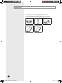
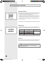
Accessories
The following accessories are supplied with the indoor unit.
The type and quantity may differ depending on the specifications.
Installation Plate
Remote Control
User’s Manual
Installation Manual
Batteries for
Remote Control
E-6
AVXWV@@_IM_E_29819-1_4.14.09.indd 6
2009-4-14 10:15:28
Selecting the Installation Location
Indoor Unit
Select a convenient location that permits the air to reach every corner of the
area to be cooled.
Pre-plan for easy and short routing of the refrigerant tubing and wiring to
the outdoor unit.
There should be no flammable gas, alkaline, substances present in the air.
Avoid location where obstacles preventing good air circulation are present.
Noise prevention should be considered in determining the unit's location.
The structure, where the unit is to be installed should be strong enough to
support the weight of the unit.
Rigid wall without vibration.
Where it is not exposed to direct sunshine.
Where the air filter can be removed and cleaned easily.
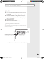
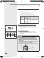
Space Requirements for Indoor Unit
Observe the clearances and maximum lengths as seen in the picture below when
installing the air conditioner.
300 mm or more
125 mm
or more
Wrap the refrigerant pipes and the drain
hose with the absorbent pad and vinyl
tape. Refer to page 15 for further details.
125 mm
or more
You can select the direction
of draining. (left or right)
The appearance of the unit may be different from the diagram depending on the model.
E-7
AVXWV@@_IM_E_29819-1_4.14.09.indd 7
2009-4-14 10:15:30
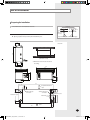
Fixing the Installation Plate
Before fixing the installation plate to the wall or window frame, you must
determine the position of the 65mm hole through which the cable, pipe and
hose pass to connect the indoor unit to the outdoor unit.
When facing the wall, the pipe and cable can be connected from the:
Installation plate
Pipe hole
(Ø65mm)
1
2
(Unit : mm) 022/028/036
(Unit : mm)
47
74
If you fix the indoor unit to a...
Follow step(s)...
Wall
3.
Window frame
4 to 6.
Fix the installation plate to the wall giving attention to the weight of the
indoor unit.
If you mount the plate to a concrete wall with anchor bolts, the anchor
bolts must not project more than 20mm.
4
Determine the positions of the wooden uprights to be attached to the
window frame.
5
Attach the wooden uprights to the window frame giving attention to the
weight of the indoor unit.
6
Attach the installation plate to the wooden uprights using tapping screws as
seen in the picture.
90
056/071
Determine the position of the pipe and drain hose hole as seen in the picture
and drill the hole with an inner diameter of 65mm so that it slants slightly
downwards.
3
45
90
Right
Left
Underside (right)
Rear (right or left)
74
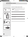
Purging the Unit
On delivery, the indoor unit is loaded with an inert Nitrogen gas.
All this gas must therefore be purged before connecting the assembly piping.
To purge the inert gas, proceed as follows.
1
Unscrew the caps at the end of each pipe.
Result: All inert gas escapes from the indoor unit.
Note
T o prevent dirt or foreign objects from getting into the pipes
during installation, do NOT remove the caps completely until you are
ready to connect the piping.
E-8
AVXWV@@_IM_E_29819-1_4.14.09.indd 8
2009-4-14 10:15:30
EEV Kit Installation
Preparing for Installation
1
Concrete
Check dimension and installation location.
Insert
2
Hole in anchor
Hole in plug
Check installation place.
By using a pattern sheet, check required installation space.
Suspension bolt(3/8" or M10)-field supply
���
���
Unit : mm
450mm X 200mm or more
(Maintenance Hole)
Maintenance hole must be located on
the ceiling.
���
���
���
���
���
���
��
��
�� ��
���
���
���
���
��
���
���
��
Required maintenance
space
���
Indoor unit pipe
connection
Required
maintenance space
���
Outdoor uint pipe
connection
Required
maintenance space
Drain hole
��
��
���
���
��
���
��
��
���
Required maintenance
space
��
E-9
AVXWV@@_IM_E_29819-1_4.14.09.indd 9
2009-4-14 10:15:31
EEV Kit Installation (Continued)
Connection of refrigerant piping & Insulation
1
Insert bot anchors, use existing ceiling supports or construct
a suitable support.
CAUTION
Ensure the ceiling is strong enough to support the weight of the
indoor unit. Before hanging the unit, test the strength of each
attached suspension bolt.
2
Connect the “IN” refrigerant pipe to the outdoor unit.
3
Connect the “OUT” refrigerant pipe to each indoor unit(A, B and C).
The liquid and gas pipes should not be crossed when piping connection.
4
Insulate the connection piping. A joint part of pipe needs double
thickness of insulation.
5
The EEV kit has to be installed that the user has no access to it. (built-in type)
Nylon band
EEV Kit body
E-10
AVXWV@@_IM_E_29819-1_4.14.09.indd 10
2009-4-14 10:15:34
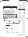
Wiring & Assigning address
A
B
C
Room A
Room B
Another
EEV Kit
Outdoor
unit
1
Connect the AC power cable and communication cable from the outdoor
unit to terminal, then connect the cable to another EEV kit.
2
Connect the AC power cable and communication cable to each indoor unit
(A, B and C).
3
EEV kit address should be set same with connected indoor units main
address.
For Example
When Main address is set as “03” that connected in pipe “A”,
the EEV kit “A” address should be set as “03”.
A
E-11
AVXWV@@_IM_E_29819-1_4.14.09.indd 11
2009-4-14 10:15:35
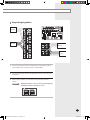
EEV Kit Installation (Continued)
Function of Display
The numbers which are displayed on left are the status of indoor unit checking
status through communication with same outdoor unit.
(If it indicates 1, 3 and 7, that means the ADDRESS of indoor unit is set to 1, 3 and 7.)
The numbers which are displayed on right indicate the ADDRESS of SW01/SW02,
SW03/SW04 and SW05/SW06 in sequential. (If it indicates 0, 1 and 2, that means the
SW01/SW02 is set to 0, the SW03/SW04 is set to 1, and the SW05/SW06 is set to 2.)
If the communication error occurs in EEV Kit, the ErC0 message will be shown on
the display alternatively.
KEY function
If you press a KEY on the PCB, the display will show you a step of appropriate
EEV Kit.
KEY No.
Meaning
K1
K2
K3
K4
Step of EEV Kit A
Step of EEV Kit B
Step of EEV Kit C
-
Example
19 (19 x 10 = 190 STEP)
-
Test run
Each indoor unit runs separately to check pipe connection and address setting.
CAUTION
If all units run at the same time, pipe cross connection and address
mismatching cannot be found.
E-12
AVXWV@@_IM_E_29819-1_4.14.09.indd 12
2009-4-14 10:15:37
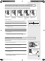
Connecting the Refrigerant Pipe
There are 2 refrigerant pipes of different diameters:
The smaller one is for the liquid refrigerant
The larger one is for the gas refrigerant
A short pipe is already fitted to the air conditioner. You may need to extend the
pipe using the assembly pipe. (optional)
The connection procedure for the refrigerant pipe varies according to the exit
position of the pipe when facing the wall:
Right(A)
Left(B)
Underside(C)
Rear
A
B
C
1
Cut out the appropriate knock-out piece on the rear of the indoor unit unless
you connect the pipe directly from the rear.
2
Smooth the cut edges.
3
Remove the protection caps of the pipes and connect the assembly pipe
to each pipe. Tighten the nuts first with your hands, and then with a torque
wrench, applying the following torque:
Outer Diameter
6.35 mm (1/4")
9.52 mm (3/8")
12.70 mm (1/2")
15.88 mm (5/8")
Torque (kgf•cm)
145~175
333~407
505~615
630~769
If you want to shorten or extend pipes, refer to page 14.
Note
Must apply refrigerant oil on the flaring area to prevent a leak.
Refrigerant oil
Torque wrench
Spanner
Flare nut
Union
4
Cut off the remaining foam insulation.
5
If necessary, bend the pipe to fit along the bottom of the indoor unit.
Then pull it out through the appropriate hole.
The pipe should not project from the rear of the indoor unit.
The bending radius should be 100 mm or more.
6
Pass the pipe through the hole in the wall.
7
For further details on how to connect to the outdoor unit and purge the air,
refer to page 8.
The pipe will be insulated and fixed permanently into position after
finishing the installation and the gas leak test; refer to page 15 for
further details.
E-13
AVXWV@@_IM_E_29819-1_4.14.09.indd 13
2009-4-14 10:15:38
Cutting/Flaring the Pipes
1
Make sure that you prepared the required tools.
(pipe cutter, reamer, flaring tool and pipe holder)
2
If you want to shorten the pipe, cut it using a pipe cutter ensuring that the cut
edge remains at 90° with the side of the pipe. There are some
examples of correctly and incorrectly cut edges below.
Oblique
Rough
Burr
3
To prevent a gas leak, remove all burrs at the cut edge of the pipe using
a reamer.
4
Carry out flaring work using flaring tool as shown below.
A
Flaring tool
York
Die
Die
Clutch type
Outer diameter
(mm)
6.35
9.52
12.70
15.88
Flare nut
A(mm)
Conventional flare tool
Clutch type
Wing nut type
1.0~1.5
1.5~2.0
1.0~1.5
1.5~2.0
1.0~1.5
1.5~2.0
1.0~1.5
1.5~2.0
Check if you flared the pipe correctly. There are some examples of
incorrectly flared pipes below.
Inclined
6
Flare tool for
R410A clutch type
0~0.5
0~0.5
0~0.5
0~0.5
Copper pipe
Copper pipe
Damaged Surface
Cracked
Uneven Thickness
Align the pipes and tighten the flare nuts first manually and then with a torque
wrench, applying the following torque.
6.35
145~175
8.70~9.10
9.52
333~407
12.80~13.20
12.70
505~615
16.20~16.60
15.88
630~769
19.30~19.70
Flare shape
(mm)
90° ±2°
Outer diameter
Connection
Flare dimension
(mm)
Torque(kgf•cm)
(mm)
45° ± 2°
5
Wing nut type
R 0.4~0.8
CAUTION
E-14
AVXWV@@_IM_E_29819-1_4.14.09.indd 14
In case of needing brazing, you must work with Nitrogen gas blowing.
2009-4-14 10:15:39
Performing Leak Test & Insulation
Leak test
LEAK TEST WITH NITROGEN (before opening valves)
In order to detect basic refrigerant leaks, before recreating the vacuum and
recirculating the R410A, it’s responsible of installer to pressurize the whole
system with nitrogen (using a pressure regulator) at a pressure above
4.1MPa (gauge).
C
D
LEAK TEST WITH R410A (after opening valves)
Before opening valves, discharge all the nitrogen into the system and
create vacuum. After opening valves check leaks using a leak detector for
refrigerant R410A.
CAUTION
Discharge all the nitrogen to create a vacuum and charge
the system.
Insulation
After checking for gas leaks in the system, insulate the pipe, hose and cables.
Then place the indoor unit on the installation plate.
1
To avoid condensation problems, place heat-resistant polyethylene foam
separately around each refrigerant pipe in the lower part of the indoor unit.
2
Wrap the refrigerant pipe and the drain hose in the rear of the indoor unit with
the absorbent pad.
Wind the pipe and hose three times to the end of the indoor unit with the
absorbent pad. (20mm interval)
3
Wind the pipe, assembly cable and drain hose with insulation tape.
4
Place the bundle (the pipe, assembly cable and drain hose) in the lower part of
the indoor unit carefully so it doesn’t project from the rear of the indoor unit.
5
Hook the indoor unit to the installation plate and move the unit to the right
and left until it is securely in place.
6
Wrap the rest of the pipe with vinyl tape.
7
Attach the pipe to the wall using clamps (optional).
Installation plate
E-15
AVXWV@@_IM_E_29819-1_4.14.09.indd 15
2009-4-14 10:15:40
Performing Leak Test & Insulation (Continued)
8 Select the insulator of the refrigerant pipe.
Insulate the gas side and liquid side pipe referring to the thickness
according to the pipe size.
The thickness according to the pipe size is a standard of the indoor
temperature of 27°C and humidity of 80%.
If installing in an unfavorable conditions, use thicker one.
Insulator’s heat-resistance temperature should be more than 120℃.
Pipe size
(mm)
Minimum thickness
of insulator (mm)
PE foam
EPDM foam
Ø6.35~ Ø15.88
13
10
-
25
19
Remarks
If you install the pipe underground,
at the seaside, a spa or on the lake,
use 1 grade thicker one according
to the pipe size.
Refrigerant pipe before EEV kit and MCU or without EEV kit and MCU
Insulation
Insulation
You can contact the gas side and liquid side pipes but the pipes
should not be pressed.
When contacting the gas side and gas side pipe, use 1 grade thicker
Liquid pipe
Gas pipe
insulator.
Refrigerant pipe after EEV kit and MCU
Install the gas side and liquid side pipes, leave 10mm of space.
10mm
10mm
10mm
When contacting the gas side and liquid side pipe, use 1 grade
thicker insulator.
CAUTION
Gas pipe
Liquid pipe
Install the insulation not to get wider and use the adhesives
on the connection part of it to prevent moisture from entering.
Wind the refrigerant pipe with insulation tape if it is exposed to
outside sunlight.
Install the refrigerant pipe respecting that the insulation does not
get thinner on the bent part or hanger of pipe.
Add the additional insulation if the insulation plate gets thinner.
Hanger
Additional insulation
a
a×3
Refrigerant pipe insulation
E-16
AVXWV@@_IM_E_29819-1_4.14.09.indd 16
2009-4-14 10:15:40
Installing and Connecting the Drain Hose of the Indoor Unit
When installing the drain hose for the indoor unit, check if condensation draining is adequate.
When passing the drain hose through the 65-mm hole drilled in the wall, check the following:
5cm
less
Ditch
The hose must
NOT slant upwards.
The end of the drain
hose must NOT be
placed under water.
Do NOT bend the hose
in different directions.
Keep a clearance of at
least 5cm between the
end of the hose and
the ground.
Do NOT place the end
of the drain hose in a
hollow.
Drain hose installation:
1
If necessary, connect the 2-meter extension drain hose to the drain hose.
2
If you use the extension drain hose, insulate the inside of the extension drain
hose with a shield.
3
Shield
Drain hose
Extension drain hose
Fit the drain hose into 1 of 2 drain hose holes, then fix the end of the drain
hose tightly with a clamp.
If you don’t use the other drain hose hole, block it with a rubber stopper.
4
Pass the drain hose under the refrigerant pipe, keeping the drain hose tight.
5
Pass the drain hose through the hole in the wall. Check if it slants downwards
as seen in the picture.
The hose will be fixed permanently into position after finishing
the installation and the gas leak test; refer to page 15 for further details.
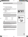
Changing Direction of the Drain Hose
You can select the direction of the drain hose, depending on where you want to
install the indoor unit.
1
Detach the rubber cap with the flyer.
Screws hole
2
Screw
Detach the drain hose by pulling it and turning to the left.
Drain hose
3
Insert the drain hose by fixing it into the groove of the drain hose and the
outlet of the drain pan.
4
Attach the rubber cap with a screwdriver by turning it to the right until it fixes
to the end of the groove.
Drain pan outlet
One of the diagrams has an illustration with the words “Screws hole” that
should be changed to “Screw hole.”
AVXWV@@_IM_E_29819-1_4.14.09.indd 17
Rubber cap
E-17
2009-4-14 10:15:42
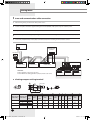
Wiring Work
Power and communication cable connection
1
Before wiring work, you must turn off all power source.
2
Indoor unit power should be supplied through the breaker(MCCB, ELB) separated by the outdoor power.
3
The power cable should be used only copper wires.
4
Connect the power cable{1(L), 2(N)} among the units within maximum length and communication cable(F1, F2) each.
5
Connect V1, V2(for DC12V) and F3, F4(for communication) when installing the wired remote control.
Outdoor Unit
Wired Remote
Control
220-240V~
L
Indoor Unit 2
EEV kit
N
Indoor Unit 1
Indoor Unit 3
N
L
N
L
N
L
ELB : Essential Installation
WARNING :
Power off before connecting any wires;
Indoor PBA will be damaged while V1,V2,F3,F4 short each other.
Indoor Unit 4
Indoor Unit 5
Indoor Unit 6
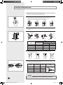
Ceiling, wall-mounted indoor unit.
Selecting compressed ring terminal
Silver solder
B
D
d1
E
F
L
d2
t
Norminal
Norminal
Standard
Standard
Standard
Standard
dimensions for dimensions for
Allowance
Allowance
Allowance
Allowance
Min. Min. Max. dimension
Min.
dimension
dimension
dimension
cable (mm2)
screw (mm)
(mm)
(mm)
(mm)
(mm)
(mm)
(mm)
(mm)
(mm)
1.5
2.5
4
4
4
4
4
6.6
8
6.6
8.5
4
9.5
±0.2
3.4
±0.2
4.2
±0.2
5.6
+0.3
-0.2
+0.3
-0.2
+0.3
-0.2
1.7
±0.2
4.1
6
16
4.3
2.3
±0.2
6
6
17.5
4.3
3.4
±0.2
6
5
20
4.3
+0.2
0
+0.2
0
+0.2
0
0.7
0.8
0.9
E-18
AVXWV@@_IM_E_29819-1_4.14.09.indd 18
2009-4-14 10:15:49
Specification of electronic wire
Power supply
MCCB
Max : 242V
Min : 198V
XA
Communication
cable
ELB or ELCB Power cable Earth cable
X A, 30mmA
0.1 sec
2.5mm2
2.5mm2
0.75~1.5mm2
Unit
Decide the capacity of ELCB(or MCCB+ELB) by below formula.
The capacity of ELCB(or MCCB+ELB) X [A] = 1.25 X 1.1 X ∑Ai
X : The capacity of ELCB(or MCCB+ELB).
∑Ai : Sum of Rating currents of each indoor unit.
Refer to each installation manual about the rating current of indoor unit.
Rating current
Model
AVXWV 022
028
036
056
071
0.13A
0.18A
0.19A
0.30A
0.30A
NHVH
0.13A
0.18A
0.19A
0.30A
0.30A
Decide the power cable specification and maximum
length within 10% power drop among indoor units.
Coef×35.6×Lk×ik
n
∑(
1000×Ak
k=1
)<
Rating current
022
028
036
056
071
10% of input
voltage[V]
coef: 1.55
Lk : Distance among each indoor unit[m], Ak: Power cable specification[mm2]
ik : Running current of each unit[A]
Example of Installation
- Total power cable length L = 100(m), Running current of each units 1[A]
- Total 10 indoor units were installed
10[A]
9[A]
1[A]
ELCB
Or MCCB+
ELB
Indoor unit2
Indoor unit1
0[m]
10[m]
Indoor unit10
20[m]
100[m]
Apply following equation.
n
∑(
k=1
Coef×35.6×Lk×ik
1000×Ak
)<
10% of input
voltage[V]
Calculation
Installing with 1 sort wire.
2.5[mm2]
2.5[mm2]
-2.2[V]
-2.0[V]
220[V]
············ 2.5[mm2] ············
208.8[V](Within 198V~242V)
it's okay
-(2.2+2.0+1.8+1.5+1.3+1.1+0.9+0.7+0.4+0.2)=-11.2[V]
Installing with 2 different sort wire.
4.0[mm2]
220[V]
4.0[mm2]
-1.4[V]
············ 2.5[mm2] ············
-1.2[V]
-(1.4+1.2+1.8+1.5+1.3+1.1+0.9+0.7+0.4+0.2)=-10.5[V]
209.5[V](Within 198V~242V)
it's okay
E-19
AVXWV@@_IM_E_31754_5.11.10.indd 19
2010-5-11 16:18:41
Wiring Work (Continued)
CAUTION
Select the power cable in accordance with relevant local and national
regulations.
Wire size must comply with local and national code.
For the power cable, use the grade of H07RN-F or H05RN-F materials.
You should connect the power cable into the power cable terminal
and fasten it with a clamp.
The unbalanced power must be maintained within 10% of supply
rating among whole indoor units.
If the power is unbalanced greatly, it may shorten the life of the
condenser. If the unbalanced power is exceeded over 10% of supply
rating, the indoor unit is protected, stopped and the error mode
indicates.
To protect the product from water and possible shock, you should keep
the power cable and the connection cord of the indoor and outdoor
units in the iron pipe.
Connect the power cable to the auxiliary circuit breaker.
An all pole disconnection from the power supply must be incorporated
in the fixed wiring(≥3mm).
You must keep the cable in a protection tube.
Keep distances of 50mm or more between power cable and
communication cable.
Maximum length of power cables are decided within 10% of power
drop. If it exceeds, you must consider another power supplying
method.
The circuit breaker(MCCB, ELB) should be considered more capacity
if many indoor units are connected from one breaker.
Use round pressure terminal for connections to the power terminal
block.
For wiring, use the designated power cable and connect it firmly,
then secure to prevent outside pressure being exerted on the terminal
board.
Use an appropriate screwdriver for tightening the terminal screws.
A screwdriver with a small head will strip the head and make proper
tightening impossible.
Over-tightening the terminal screws may break them.
See the table below for tightening torque for the terminal screws.
Tightening torque(kgf•cm)
M4
12.0~14.7
E-20
AVXWV@@_IM_E_29819-1_4.14.09.indd 20
2009-4-14 10:15:50
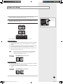
Indoor Unit Setting
1
Before installing the indoor unit, assign an address to the indoor unit
according to the air conditioning system plan.
2
The address of the indoor unit is assigned by adjusting MAIN(SW01, SW02) and
RMC(SW03, SW04) rotary switches.
SW05
SW01
SW02
SW03
SW04
SW06
Cover PCB
SW07
The designs and shape are subject to change according to the model.
Setting Main Address
The MAIN address is for communication between the indoor unit and the
outdoor unit. Therefore, you must set it to operate the air conditioner
properly.
You can set the MAIN address from ‘00’ to ‘99’ by mixing SW01 and SW02.
The MAIN address from ‘00’ to ‘99’ should differ from each other.
Check the indoor unit address on the plan that you are to install and set
the address according to the plan.
Note
You may not need to set main address if you selected Auto
Address Setting from the outdoor unit: see details on the
outdoor unit installation manual.
For Example
When MAIN address is set as "12".
Setting RMC Address
The SW03, SW04 RMC switch is the address setting switch for controlling
the indoor unit with the centralized controller.
You must set the SW03, SW04 and K2 switch when using the centralized
controller.
For Example
When RMC address is set as "12".
SW03
SW04
E-21
AVXWV@@_IM_E_29819-1_4.14.09.indd 21
2009-4-14 10:15:50
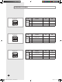
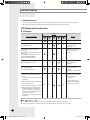
Additional Functions
�� �� �� ��
No.
SW05
����
�� �� �� ��
����
����
OFF
-
-
-
K2
Centralized controller
Not use
Use
K3
-
-
-
K4
-
-
-
Function
ON
OFF
K5
Heating Current Temperature
Compensation
+2°C
+5°C
K6
Filter Time
1,000 hours
2,000 hours
K7
-
-
-
K8
-
-
-
Function
ON
OFF
K9
Indoor Expansion Valve For
Heating Stop
Fix 80 step
0 or 80 step
K10
Wired Remocon Group Master
Not use
Use
K11
External control
Not use
Use
K12
-
-
-
No.
SW07
ON
K1
No.
SW06
�� ��� ��� ���
Function
E-22
AVXWV@@_IM_E_29819-1_4.14.09.indd 22
2009-4-14 10:15:51
Final Checks and User Tips
To complete the installation, perform the following checks and tests to ensure
that the air conditioner operates correctly.
1
Check the following:
Strength of the installation site
Tightness of pipe connection to detect gas leak
Electric wiring connection
Heat-resistant insulation of the pipe
Drainage
Grounding conductor connection
Correct operation (follow the steps below)
2
Press the
button and check the following:
The indicator on the indoor unit lights up.
The airflow blade opens and the fan gears up for operation.
3
Press any button and check the following:
The appropriate indicator lights up and the air conditioner operates
according to the selected mode or function.
4
Press the
button and check the following:
The airflow blades work properly.
After finishing the installation of the air conditioner, explain the following to
the user: (refer to appropriate pages in the User’s Manual.)
1
How to start and stop the air conditioner
2
How to select the modes and functions
3
How to adjust the temperature and fan speed
4
How to adjust the airflow direction
5
How to set the timers
6
How to clean and replace the filters
When you complete the installation successfully, hand over the User’s
Manual and this Installation Manual to the user for storage in a handy and
safe place.
E-23
AVXWV@@_IM_E_29819-1_4.14.09.indd 23
2009-4-14 10:15:52
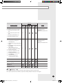
Troubleshooting
Detection of errors
If an error occurs during the operation, one or more LED flickers and the operation is stopped except the LED.
If you re-operate the air conditioner, it operates normally at first, then detect an error again.
LED Display on the indoor unit
LED Display
Indicators
Abnormal conditions
Remarks
X
Power reset
Error of temperature sensor in indoor
unit (OPEN/SHORT)
X
Error of heat exchanger sensor in
indoor unit
Error of heat exchanger OUT sensor in
indoor unit
Error of outlet temperature sensor in
indoor unit (OPEN/SHORT):
For heat pump models only
Error of indoor fan motor:
Below 450RPM for 15 minutes
X
X
X
X
Error of outdoor temperature sensor
Error of COND sensor
Error of DISCHARGE sensor
X
X
X
X
X
X
X
X
X
X
On
Displayed on appropriate
indoor unit which is
operating
X
Displayed on appropriate
indoor unit which is
operating
X
Displayed on appropriate
indoor unit which is
operating
Displayed on outdoor unit
1. No communication for 2 minutes
between indoor unit and outdoor
unit
(communication error for more than
2 minutes)
2. Indoor unit receiving the communication
error from outdoor unit
3. Outdoor unit tracking 3 minute error
4. When sending the communication
error from outdoor unit due to the
mismatching of the communication
numbers and installed numbers after
completion of tracking
(communication error for more than
2 minutes)
Displayed on appropriate
indoor unit which is
operating
1. Error of indoor unit:
Displayed on the indoor
unit regardless of
operation
X
X
X
2. Error of outdoor unit:
Displayed on the indoor
unit which is operating
Flickering X Off
If you turn off the air conditioner when the LED is flickering, the LED is also turned off.
If you re-operate the air conditioner, it operates normally at first, then detects an error again.
E-24
AVXWV@@_IM_E_29819-1_4.14.09.indd 24
2009-4-14 10:15:55
Indicators
Abnormal conditions
Remarks
Self-diagnostic error
(including the indoor unit not detected)
1. Error of electronic expansion valve
close
2. Error of electronic expansion valve
open
3. Breakaway of EVA OUT sensor
4. Breakaway of EVA IN sensor
Displayed on appropriate
indoor unit which is
operating
Displayed on outdoor unit
5. Breakaway of COND MID sensor
6. 2nd detection of refrigerant
completely leak
7. 2nd detection of high temperature
COND
8. 2nd detection of high temperature
DISCHARGE
9. COMP DOWN due to 2nd
detection of low pressure switch
10. Error of reverse phase
11. Compressor down due to 6th
detection of freezing
12. Self-diagnosis of condensation
sensor (G8, G9)
13. Compressor down due to
condensation ratio control
X
X
Displayed on appropriate
indoor unit which is
operating
Displayed on outdoor unit
X
X
Error of float switch
X
X
Error of setting option switches for
optional accessories
X
X
EEPROM error
X
X
X
X
EEPROM option error
On
Flickering X Off
If you turn off the air conditioner when the LED is flickering, the LED is also turned off.
If you re-operate the air conditioner, it operates normally at first, then detects an error again.
E-25
AVXWV@@_IM_E_29819-1_4.14.09.indd 25
2009-4-14 10:15:56
"EEE Yönetmeliğine Uygundur"
"This EEE is compliant with RoHS"
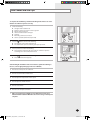
AVXC1@@_IM_E_29824-1_5.05.09.indd 30
2009-5-12 8:46:05
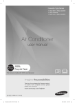
INSTALLATION
MANUAL
Wall-mounted Type Series
Vivace Type : AVXWV
NHVH
Air Conditioner
E DB98-29819A(1)
AVXWV@@_IM_E_31754_5.08.10.indd 27
2010-5-8 10:45:09