1
Contents
A
INSTALLATION PARTS
Safety precautions ......................................................................................................................................................3
Accessories....................................................................................................................................................................5
Selecting the installation location ..........................................................................................................................6
Indoor unit installation .............................................................................................................................................7
Purging the unit ..........................................................................................................................................................8
Connecting the refrigerant pipe .............................................................................................................................9
Cutting/flaring the pipes........................................................................................................................................ 10
Performing leak test & insulation ........................................................................................................................ 11
Drain hose installation............................................................................................................................................ 12
Charging direction of the drain hose ................................................................................................................. 13
Wiring work ............................................................................................................................................................... 14
Setting an indoor unit address and installation option................................................................................. 17
Final check and trial operation ............................................................................................................................. 26
Providing information for user ............................................................................................................................. 26
Troubleshooting....................................................................................................................................................... 26
2
Safety
precautions
A
(Carefully follow the precautions listed below because they are essential to guarantee the safety of the
equipment.)
WARNING
xAlways disconnect the air conditioner from the power supply before servicing it or
accessing its internal components.
xVerify that installation and testing operations are performed by qualified personnel.
xVerify that the air conditioner is not installed in an easily accessible area.
GENERAL INFORMATION
X Carefully read the content of this manual before installing the air conditioner and store the manual in a safe place in
order to be able to use it as reference after installation.
X For maximum safety, installers should always carefully read the following warnings.
X Store the operation and installation manual in a safe location and remember to hand it over to the new owner if the
air conditioner is sold or transferred.
X This manual explains how to install an indoor unit with a split system with two SAMSUNG units. The use of other types
of units with different control systems may damage the units and invalidate the warranty. The manufacturer shall not
be responsible for damages arising from the use of non compliant units.
X This product has been determined to be in compliance with the Low Voltage Directive (2006/95/EC),
and the Electromagnetic Compatibility Directive (2004/108/EC) of the European Union.
X The manufacturer shall not be responsible for damage originating from unauthorized changes or the improper connection
of electric and hydraulic lines. Failure to comply with these instructions or to comply with the requirements set forth in the
“Operating limits” table, included in the manual, shall immediately invalidate the warranty.
X The air conditioner should be used only for the applications for which it has been designed: the indoor unit is not
suitable to be installed in areas used for laundry.
X Do not use the units if damaged. If problems occur, switch the unit off and disconnect it from the power supply.
X In order to prevent electric shocks, fires or injuries, always stop the unit, disable the protection switch and contact
SAMSUNG’s technical support if the unit produces smoke, if the power cable is hot or damaged or if the unit is very
noisy.
X Always remember to inspect the unit, electric connections, refrigerant tubes and protections regularly.
These operations should be performed by qualified personnel only.
X The unit contains moving parts, which should always be kept out of the reach of children.
X Do not attempt to repair, move, alter or reinstall the unit. If performed by unauthorized personnel, these operations
may cause electric shocks or fires.
X Do not place containers with liquids or other objects on the unit.
X All the materials used for the manufacture and packaging of the air conditioner are recyclable.
X The packing material and exhaust batteries of the remote control(optional) must be disposed of in accordance with
current laws.
X The air conditioner contains a refrigerant that has to be disposed of as special waste. At the end of its life cycle, the air
conditioner must be disposed of in authorized centers or returned to the retailer so that it can be disposed of correctly
and safely.
INSTALLING THE UNIT
IMPORTANT: When installing the unit, always remember to connect first the refrigerant tubes, then the electrical lines.
Always disassemble the electric lines before the refrigerant tubes.
X Upon receipt, inspect the product to verify that it has not been damaged during transport. If the product appears
damaged, DO NOT INSTALL it and immediately report the damage to the carrier or retailer (if the installer or the
authorized technician has collected the material from the retailer.)
X After completing the installation, always carry out a functional test and provide the instructions on how to operate
the air conditioner to the user.
X Do not use the air conditioner in environments with hazardous substances or close to equipment that release free
flames to avoid the occurrence of fires, explosions or injuries.
X The air conditioner should be used only for the applications for which it has been designed: the indoor unit is not
suitable to be installed in areas used for laundry.
3
Safety precautions
A
X Our units must be installed in compliance with the spaces indicated in the installation manual to ensure either
accessibility from both sides or ability to perform routine maintenance and repairs. The units’ components must be
accessible and that can be disassembled in conditions of complete safety either for people or things.
For this reason, where it is not observed as indicated into the Installation Manual, the cost necessary to reach and repair
the unit (in safety, as required by current regulations in force) with slings, trucks, scaffolding or any other means of
elevation won’t be considered in-warranty and charged to end user.
POWER SUPPLY LINE, FUSE OR CIRCUIT BREAKER
X Always make sure that the power supply is compliant with current safety standards. Always install the air conditioner in
compliance with current local safety standards.
X Always verify that a suitable grounding connection is available.
X Verify that the voltage and frequency of the power supply comply with the specifications and that the installed power is
sufficient to ensure the operation of any other domestic appliance connected to the same electric lines.
X Always verify that the cut-off and protection switches are suitably dimensioned.
X Verify that the air conditioner is connected to the power supply in accordance with the instructions provided in the
wiring diagram included in the manual.
X Always verify that electric connections (cable entry, section of leads, protections…) are compliant with the electric
specifications and with the instructions provided in the wiring scheme. Always verify that all connections comply with
the standards applicable to the installation of air conditioners.
X Make sure that you earth the cables.
- Do not connect the earth wire to the gas pipe, water pipe, lighting rod or telephone wire.
If earthing is not complete, electric shock or fire may occur.
X Install the circuit breaker.
- If the circuit breaker is not installed, electric shock or fire may occur.
X Make sure that the condensed water dripping from the drain hose runs out properly and safely.
X Install the power cable and communication cable of the indoor and outdoor unit at least 1m
away from the electric appliance.
X Install the indoor unit away from lighting apparatus using the ballast.
- If you use the wireless remote control, reception error may occur due to the ballast of the
lighting apparatus.
X Do not install the air conditioner in following places.
- Place where there is mineral oil or arsenic acid.
Resin parts flame and the accessories may drop or water may leak.
The capacity of the heat exchanger may reduce or the air conditioner may be out of order.
- The place where corrosive gas such as sulfurous acid gas generates from the vent pipe or air
outlet.
The copper pipe or connection pipe may corrode and refrigerant may leak.
- The place where there is a machine that generates electromagnetic waves.
The air conditioner may not operate normally due to control system.
- The place where there is a danger of existing combustible gas, carbon fiber or flammable
dust.
The place where thinner or gasoline is handled.
Gas may leak and it may cause fire.
4
Accessories
A
The following accessories are supplied with the indoor unit.
The type and quantity may differ depending on the specifications.
Slim Duct :
Installation Plate
Remote Control
Batteries for
Remote Control
Installation manual
User's manual
5
Selecting
the installation location
A
Indoor Unit
X
X
X
X
X
X
X
X
Where airflow is not blocked.
Where cool air can be distributed throughout the room.
Install the refrigerant piping length and the height difference of both indoor and outdoor units as
indicated in the installation diagram.
Wall that prevents vibration and is strong enough to hold the product weight.
Out of the direct sunlight .
1m or more away from the TV or radio (to prevent the screen from being distorted or noise from being
generated).
As far away as possible from fluorescent and incandescent lights (so that the remote control can be
operated well).
A place where the air filter can be replaced easily.
X Avoid the following places to prevent malfunction of the unit
- Where there is machine oil
- Salty environment such as the seaside areas
- Where sulfide gas exists
- Other special atmosphere areas
Space requirements for installation & service
Observe the clearances and maximum lengths as seen in the picture below when installing the
air conditioner.
300 mm or more
125 mm
or more
Wrap the refrigerant pipes and the drain
hose with the absorbent pad and vinyl
tape. Refer to page 17 for further details.
125 mm
or more
You can select the direction
of draining. (left or right)
KThe appearance of the unit may be different from the diagram depending on the model.
6
Indoor
unit installation
A
Before fixing the installation plate to the wall or window frame,
you must determine the position of the 65mm hole through which
the cable, pipe and hose pass to connect the indoor unit to the
outdoor unit.
When facing the wall, the pipe and cable can be connected from
the:
X
X
X
X
1
Right
Left
Underside (right)
Rear (right or left)
Determine the position of the pipe and drain hose hole as seen in
the picture and drill the hole with an inner diameter of 65mm so
that it slants slightly downwards.
(Unit : mm) 77022/028/03677
3.
Window frame
4 to 6.
Fix the installation plate to the wall giving attention to the weight
of the indoor unit.
± If you mount the plate to a concrete wall with anchor bolts,
the anchor bolts must not project more than 20mm.
27
Wall
Pipe hole
(Ø65mm)
120
(Unit : mm)
68
77045/056/07177
Pipe hole
(Ø65mm)
34
Follow step(s)...
34
3
If you fix the indoor unit to a...
27
2
140
4
Determine the positions of the wooden uprights to be attached to
the window frame.
5
Attach the wooden uprights to the window frame giving attention
to the weight of the indoor unit.
6
Attach the installation plate to the wooden uprights using tapping
screws as seen in the picture.
68
7
Purging
the unit
A
Upon delivery, there may be inert gas inside the indoor unit.
Purge the gas from the indoor unit before connecting the
assembly pipe.
Unscrew the caps at the end of each pipe.
Result:
All inert gas exhausts from the indoor unit.
± To prevent dirt or foreign substances from getting into the
pipes during installation, do NOT remove the caps
completely until you are ready to connect the pipes.
8
Connecting the refrigerant pipe
Connect indoor and outdoor units with field-supplied copper pipes by
means of flare connections. Use insulated seamless refrigeration grade
pipe only, (Cu DHP type according to ISO1337), degreased and deoxidized,
suitable for operating pressures of at least 4200 kPa and for burst pressure
of at least 20700 kPa. Under no circumstances must sanitary type copper
pipe be used.
There are 2 refrigerant pipes of different diameters:
X The smaller one is for the liquid refrigerant
X The larger one is for the gas refrigerant
A short pipe is already fitted to the air conditioner. You may need to
extend the pipe using the assembly pipe. (optional)
The connection procedure for the refrigerant pipe varies according to the
exit position of the pipe when facing the wall:
X Right(A)
X Left(B)
X Underside(C)
X Rear
1
Cut out the appropriate knock-out piece on the rear of the indoor unit
unless you connect the pipe directly from the rear.
2
Smooth the cut edges.
3
Remove the protection caps of the pipes and connect the assembly pipe
to each pipe. Tighten the nuts first with your hands, and then with a torque
wrench, applying the following torque:
Outer Diameter
6.35 mm
9.52 mm
12.70 mm
15.88 mm
A
B
C
Refrigerant oil
Torque
LHGtDN
140~180
350~430
500~620
690~830
/tN
14~18
34~42
49~61
68~82
± If you want to shorten or extend pipes, refer to page 10.
4
Cut off the remaining foam insulation.
5
If necessary, bend the pipe to fit along the bottom of the indoor unit.
Then pull it out through the appropriate hole.
X The pipe should not project from the rear of the indoor unit.
X The bending radius should be 100 mm or more.
6
Pass the pipe through the hole in the wall.
7
For further details on how to connect to the outdoor unit and purge the air,
refer to page 8.
Torque wrench
Spanner
Flare nut
Union
± The pipe will be insulated and fixed permanently into position after
finishing the installation and the gas leak test; refer to page 17 for
further details.
± DO NOT WALL UP THE PIPE CONNECTION !
All refrigerant pipe connection must be easy accessible and serviceable.
9
Cutting/flaring the pipes
1
Make sure that you prepared the required tools.
(pipe cutter, reamer, flaring tool and pipe holder)
2
If you want to shorten the pipe, cut it using a pipe cutter ensuring that
the cut edge remains at 90° with the side of the pipe. There are some
examples of correctly and incorrectly cut edges below.
Oblique
Rough
Burr
3
To prevent a gas leak, remove all burrs at the cut edge of the pipe using a
reamer.
4
Carry out flaring work using flaring tool as shown below.
A
Flaring tool
York
Die
Die
Clutch type
Wing nut type
Outer diameter
(mm)
Flare tool for
R410A clutch type
6.35
9.52
12.70
15.88
0~0.5
0~0.5
0~0.5
0~0.5
A(mm)
Conventional flare tool
Clutch type
Wing nut type
1.0~1.5
1.5~2.0
1.0~1.5
1.5~2.0
1.0~1.5
1.5~2.0
1.0~1.5
1.5~2.0
Damaged Surface Cracked
Uneven Thickness
Align the pipes and tighten the flare nuts first manually and then with a
torque wrench, applying the following torque.
Outer diameter Connection Torque Flare dimension
(mm)
(mm)
LHGtDN
/tN
10
Copper
pipe
Check if you flared the pipe correctly. There are some examples of
incorrectly flared pipes below.
Inclined
6
Flare nut
140~180
14~18
8.70~9.10
9.52
350~430
34~42
12.80~13.20
12.70
500~620
49~61
16.20~16.60
15.88
690~830
68~82
19.30~19.70
90° ±2°
6.35
Flare shape
(mm)
45° ± 2°
5
Copper pipe
R 0.4~0.8
In case of needing brazing,
you must work with Nitrogen
gas blowing.
Performing
leak test & insulation
A
Leak test
LEAK TEST WITH NITROGEN (before opening valves)
In order to detect basic refrigerant leaks, before recreating the
vacuum and recirculating the R410A, it’s responsible of installer
to pressurize the whole system with nitrogen (using a pressure
regulator) at a pressure above 4.1MPa (gauge).
C
D
LEAK TEST WITH R410A (after opening valves)
Before opening valves, discharge all the nitrogen into the system
and create vacuum. After opening valves check leaks using a
leak detector for refrigerant R410A.
Discharge all the nitrogen to create a vacuum and
charge the system.
Insulation
After checking for gas leaks in the system, insulate the pipe,
hose and cables. Then place the indoor unit on the installation
plate.
1
To avoid condensation problems, place heat-resistant polyethylene foam separately around each refrigerant pipe in the
lower part of the indoor unit.
2
Wrap the refrigerant pipe and the drain hose in the rear of the
indoor unit with the absorbent pad.
± Wind the pipe and hose three times to the end of the
indoor unit with the absorbent pad. (20mm interval)
3
Wind the pipe, assembly cable and drain hose with insulation
tape.
4
Place the bundle (the pipe, assembly cable and drain hose) in
the lower part of the indoor unit carefully so it doesn’t project
from the rear of the indoor unit.
5
Hook the indoor unit to the installation plate and move the unit
to the right and left until it is securely in place.
6
Wrap the rest of the pipe with vinyl tape.
7
Attach the pipe to the wall using clamps (optional).
Installation plate
11
Drain hose installation
A
When installing the drain hose for the indoor unit, check if condensation draining is adequate.
When passing the drain hose through the 65-mm hole drilled in the wall, check the following:
5cm
less
Ditch
The hose must
NOT slant upwards.
The end of the drain
hose must NOT be
placed under water.
Do NOT bend the hose
in different directions.
Keep a clearance of at
least 5cm between the
end of the hose and
the ground.
Do NOT place the end
of the drain hose in a
hollow.
Drain hose installation:
1
If necessary, connect the 2-meter extension drain hose to the
drain hose.
2
If you use the extension drain hose, insulate the inside of the
extension drain hose with a shield.
3
Fit the drain hose into 1 of 2 drain hose holes, then fix the end of
the drain hose tightly with a clamp.
± If you don’t use the other drain hose hole, block it with a
rubber stopper.
4
Pass the drain hose under the refrigerant pipe, keeping the drain
hose tight.
5
Pass the drain hose through the hole in the wall. Check if it slants
downwards as seen in the picture.
± The hose will be fixed permanently into position after
finishing the installation and the gas leak test; refer to page
12 for further details.
±DO NOT WALL UP THE DRAIN HOSE CONNECTION !
Drain hose connection must be easy accessible and
serviceable.
12
Shield
Drain hose
Extension drain hose
Changing direction of the drain hose
You can select the direction of the drain hose, depending on
where you want to install the indoor unit.
1
Detach the rubber cap with the flyer.
Screw hole
Screw
2
Detach the drain hose by pulling it and turning to the left.
Drain hose
3
Insert the drain hose by fixing it into the groove of the drain hose
and the outlet of the drain pan.
Drain pan outlet
4
Attach the rubber cap with a screwdriver by turning it to the right
until it fixes to the end of the groove.
Rubber cap
13
Wiring
work
A
Power and communication cable connection
1
Before wiring work, you must turn off all power source.
2
Indoor unit power should be supplied through the breaker( ELCB or MCCB+ELB ) separated by the
outdoor power.
ELCB:Earth Leakage Circuit Breaker
MCCB:Molded Case Circuit Breaker
ELB:Earth Leakage Breaker
3
The power cable should be used only copper wires.
4
Connect the power cable{1(L), 2(N)} among the units within maximum length and communication
cable(F1, F2) each.
5
Connect F3, F4(for communication) when installing the wired remote control.
Outdoor Unit
Wired Remote
Control
220-240V~
or
ELCB
Indoor Unit 1
Indoor Unit 2
V2
L
V1
N
MCCB+
ELB
Indoor Unit 3
K ELCB : Essential Installation
WARNING :
Power off before connecting any wires;
Indoor PBA will be damaged while V1,V2,F3,F4 short each
other.
K The EEV Kit is optional component.
EEV kit
N
Indoor Unit 4
Indoor Unit 5
L
N
L
N
L
Indoor Unit 6
K Ceiling, wall-mounted indoor unit.
Selecting compressed ring terminal
Silver solder
B
D
d1
E
F
L
d2
t
Norminal Norminal
Standard
Standard
Standard
dimensions dimensions Standard
Allowance
Allowance
Allowance
Allowance
dimension
dimension
Min. Min. Max. dimension
Min.
for cable for screw dimension
(mm)
(mm)
(mm)
(mm)
2
(mm)
(mm)
(mm)
(mm)
(mm)
(mm )
4
6.6
+0.3
+0.2
1.5
±0.2
3.4
1.7
±0.2
4.1
6
16
4.3
0.7
4
8
-0.2
0
4
6.6
+0.3
+0.2
2.5
±0.2
4.2
2.3
±0.2
6
6 17.5
4.3
0.8
4
8.5
-0.2
0
+0.3
+0.2
4
4
9.5
±0.2
5.6
3.4
±0.2
6
5
20
4.3
0.9
-0.2
0
14
Specification of electronic wire
Power supply
MCCB
Max : 242V
Min : 198V
XA
ELB or ELCB Power cable Earth cable
X A, 30mmA
0.1 s
2.5mm2
Communication cable
2.5mm2
0.75~1.5mm2
X Decide the capacity of ELCB(or MCCB+ELB) by below formula.
X Supply cords of parts of appliances for outdoor use shall not be lighter
KRating current
than polychloroprene sheathed flexible cord.
(Code designation IEC:60245 IEC 57 / CENELEC: H05RN-F )
The capacity of ELCB(or MCCB+ELB) X [A] = 1.25 X 1.1 X ∑Ai
7X : The capacity of ELCB(or MCCB+ELB).
7∑ Ai : Sum of Rating currents of each indoor unit.
7Refer to each installation manual about the rating current of indoor unit.
X
n
Coef×35.6×Lk×ik
AM7FNTD7
70227
70287
70367
70567
) < 10% of input voltage[V]
1000×Ak
k=1
Model
AM7FNQD7
Decide the power cable specification and maximum length within
10% power drop among indoor units.
∑(
Unit
Rating
current
70717
0.16A
0.16A
0.18A
0.27A
0.30A
70227
70287
70367
70457
70567
70717
0.16A
0.16A
0.18A
0.24A
0.27A
0.30A
7coef: 1.55
7Lk: Distance among each indoor unit[m], Ak: Power cable specification[mm2]
ik: Running current of each unit[A]
Example of Installation
- Total power cable length L = 100(m), Running current of each units 1[A]
- Total 10 indoor units were installed
10[A]
ELCB
9[A]
1[A]
or MCCB+
ELB
Indoor unit1
0[m]
10[m]
Indoor unit2
Indoor unit10
20[m]
100[m]
X Apply following equation.
n
Coef×35.6×Lk×ik
∑(
1000×Ak
k=1
)<
10% of input
voltage[V]
K Calculation
OInstalling
with 1 sort wire.
2.5[mm2]
2.5[mm2]
-2.2[V]
-2.0[V]
220[V]
208.8[V](Within 198V~242V)
it's okay
-(2.2+2.0+1.8+1.5+1.3+1.1+0.9+0.7+0.4+0.2)=-11.2[V]
OInstalling
220[V]
············ 2.5[mm2] ············
with 2 different sort wire.
4.0[mm2]
4.0[mm2]
-1.4[V]
-1.2[V]
············ 2.5[mm2] ············
-(1.4+1.2+1.8+1.5+1.3+1.1+0.9+0.7+0.4+0.2)=-10.5[V]
209.5[V](Within 198V~242V)
it's okay
15
Wiring work(Cont.)
A
X
X
X
X
X
X
X
X
X
X
X
X
X
X
X
X
X
Select the power cable in accordance with relevant local and national regulations.
Wire size must comply with local and national code.
For the power cable, use the grade of H07RN-F or H05RN-F materials.
You should connect the power cable into the power cable terminal and fasten it with a clamp.
The unbalanced power must be maintained within 10% of supply rating among whole indoor
units.
If the power is unbalanced greatly, it may shorten the life of the condenser. If the unbalanced
power is exceeded over 10% of supply rating, the indoor unit is protected, stopped and the
error mode indicates.
To protect the product from water and possible shock, you should keep the power cable and
the connection cord of the indoor and outdoor units in the iron pipe.
Connect the power cable to the auxiliary circuit breaker.
An all pole disconnection from the power supply must be incorporated in the fixed
wiring(≥3mm).
You must keep the cable in a protection tube.
Keep distances of 50mm or more between power cable and communication cable.
Maximum length of power cables are decided within 10% of power drop. If it exceeds, you
must consider another power supplying method.
The circuit breaker(ELCB or MCCB+ELB) should be considered more capacity if many indoor
units are connected from one breaker.
Use round pressure terminal for connections to the power terminal block.
For wiring, use the designated power cable and connect it firmly, then secure to prevent outside pressure being exerted on the terminal board.
Use an appropriate screwdriver for tightening the terminal screws. A screwdriver with a small
head will strip the head and make proper tightening impossible.
Over-tightening the terminal screws may break them.
See the table below for tightening torque for the terminal screws.
Tightening torque
16
Ntm
kgftcm
M3.5
0.8~1.0
8.0~10.0
M4
1.2~1.5
12.0~14.7
Setting
an indoor unit address and
A
installation option
Set the indoor unit address and installation option with remote controller option.
Set the each option separately since you cannot set the ADDRESS setting and indoor
unit installation setting option at the same time. You need to set twice when setting
indoor unit address and installation option.
The procedure of option setting
Option setting mode
Entering mode for
option setting
Mode change
High Temp Button
High Fan Button
Low Temp Button
Low Fan Button
Step 1. Entering mode to set option
1. Remove batteries from the remote controller.
2. Insert batteries and enter the option setting mode while pressing High Temp button and Low Temp button.
3.
Check if you have entered the option setting status.
Step 2. The procedure of option setting
After entering the option setting status, select the option as listed below.
Option setting is available from SEG1 to SEG 24
X SEG1, SEG7, SEG13, SEG19 are not set as page option.
X Set the SEG2~SEG6, SEG8~SEG12 as ON status and SEG14~18, SEG20~24 as OFF status.
SEG1 SEG2 SEG3 SEG4 SEG5 SEG6 SEG7 SEG8 SEG9 SEG10 SEG11 SEG12
0
X
X
X
X
X
1
X
X
X
X
On(SEG1~12)
Off(SEG13~24)
X
SEG13 SEG14 SEG15 SEG16 SEG17 SEG18 SEG19 SEG20 SEG21 SEG22 SEG23 SEG24
2
X
X
X
X
X
3
X
X
X
X
X
17
Setting
an indoor unit address and
A
installation option (Cont.)
Option setting
1. Setting SEG2, SEG3 option
Press Low Fan button(∨) to enter SEG2 value.
Press High Fan button(∧) to enter SEG3 value.
…
Each time you press the button,
Status
will be selected in rotation.
SEG2
SEG3
SEG4
SEG5
SEG6
SEG8
SEG9
SEG10
SEG11
SEG12
SEG14
SEG15
2. Setting Cool mode
Press Mode button to be changed to Cool mode in the ON status.
3. Setting SEG4, SEG5 option
Press Low Fan button(∨) to enter SEG4 value.
Press High Fan button(∧) to enter SEG5 value.
…
Each time you press the button,
will be selected in rotation.
4. Setting Dry mode
Press Mode button to be changed to DRY mode in the ON status.
5. Setting SEG6, SEG8 option
Press Low Fan button(∨) to enter SEG6 value.
Press High Fan button(∧) to enter SEG8 value.
…
Each time you press the button,
will be selected in rotation.
6. Setting Fan mode
Press Mode button to be changed to FAN mode in the ON status.
7. Setting SEG9, SEG10 option
Press Low Fan button(∨) to enter SEG9 value.
Press High Fan button(∧) to enter SEG10 value.
…
Each time you press the button,
will be selected in rotation.
8. Setting Heat mode
Press Mode button to be changed to HEAT mode in the ON status.
9. Setting SEG11, SEG12 option
Press Low Fan button(∨) to enter SEG11 value.
Press High Fan button(∧) to enter SEG12 value.
Each time you press the button,
…
will be selected in rotation.
10. Setting Auto mode
Press Mode button to be changed to AUTO mode in the OFF status.
11. Setting SEG14, SEG15 option
Press Low Fan button(∨) to enter SEG14 value.
Press High Fan button(∧) to enter SEG15 value.
Each time you press the button,
…
18
will be selected in rotation.
Option setting
Status
12. Setting Cool mode
Press Mode button to be change to Cool mode in the OFF status.
13. Setting SEG16, SEG17 option
Press Low Fan button(∨) to enter SEG16 value.
Press High Fan button(∧) to enter SEG17 value.
…
Each time you press the button,
will be selected in rotation.
SEG16
SEG17
SEG18
SEG20
SEG21
SEG22
SEG23
SEG24
14. Setting Dry mode
Press Mode button to be change to Dry mode in the OFF status.
15. Setting SEG18, SEG20 option
Press Low Fan button(∨) to enter SEG18 value.
Press High Fan button(∧) to enter SEG20 value.
…
Each time you press the button,
will be selected in rotation.
16. Setting Fan mode
Press Mode button to be change to Fan mode in the OFF status.
17. Setting SEG21, SEG22 option
Press Low Fan button(∨) to enter SEG21 value.
Press High Fan button(∧) to enter SEG22 value.
…
Each time you press the button,
will be selected in rotation.
18. Setting Heat mode
Press Mode button to be change to HEAT mode in the OFF status.
19. Setting SEG23, SEG24 mode
Press Low Fan button(∨) to enter SEG23 value.
Press High Fan button(∧) to enter SEG24 value.
…
Each time you press the button,
will be selected in rotation.
Step 3. Check the option you have set
After setting option, press
button to check whether the option code you input is correct or not.
¤
¤
¤
¤
¤
¤
¤
¤
¤
Step 4. Input option
Press operation button
with the direction of remote control for set.
For the correct option setting, you must input the option twice.
Step 5. Check operation
1. Reset the indoor unit by pressing the RESET button of indoor unit or outdoor unit.
2. Take the batteries out of the remote controller and insert them again and then press the operation button.
19
Setting
an indoor unit address and
A
installation option (Cont.)
Setting an indoor unit address (MAIN/RMC)
Indoor Unit
1(L)
2(N)
1. Check whether power is supplied or not.
F2
F1
- When the indoor unit is not plugged in, there should be additional
power supply in the indoor unit.
2. The panel(display) should be connected to an indoor unit to receive option.
3. Before installing the indoor unit, assign an address to the indoor unit according
to the air conditioning system plan.
4. Assign an indoor unit address by wireless remote controller.
- The initial setting status of indoor unit ADDRESS(MAIN/RMC) is “0A0000-100000-200000-300000”.
Option No. : 0AXXXX-1XXXXX-2XXXXX-3XXXXX
Option
SEG1
SEG2
SEG3
SEG4
SEG5
SEG6
Explanation
PAGE
Mode
Setting Main address
100-digit of indoor
unit address
10-digit of indoor
unit
The unit digit of
an indoor unit
Remote
Controller
Display
Indication Details Indication Details Indication Details Indication Details Indication Details Indication Details
Indication
and Details
0
Option
SEG7
Explanation
PAGE
0
No Main
address
1
Main
address
setting
mode
A
SEG8
SEG9
0~9
100-digit
SEG10
Setting RMC address
0~9
10-digit
0~9
A unit
digit
SEG11
SEG12
Group channel(*16)
Group address
Remote
Controller
Display
Indication Details
Indication
and Details
__
Indication Details
0
No RMC
address
1
RMC
address
setting
mode
1
__
Indication Details Indication Details
RMC1
0~2
RMC2
0~F
X When “A”~”F” is entered to SEG5~6, the indoor unit MAIN ADDRESS is not changed.
X If you set the SEG 3 as 0, the indoor unit will maintain the previous MAIN ADDRESS even if you input the option value of SEG5~6.
X If you set the SEG 9 as 0, the indoor unit will maintain previous RMC ADDRESS even if you input the option value of SEG11~12.
X You cannot set SEG11 and SEG12 as F value at the same time.
20
Setting an indoor unit installation option
(suitable for the condition of each installation location)
1. Check whether power is supplied or not.
Indoor Unit
- When the indoor unit is not plugged in, there should be additional
power supply in the indoor unit.
1(L)
2(N)
F2
F1
2. The panel(display) should be connected to an indoor unit to receive
option.
3. Set the installation option according to the installation condition of an air
conditioner.
- The default setting of an indoor unit installation option is
“020010-100000- 200000-300000”.
- Individual control of a remote controller(SEG20) is the function that controls an
indoor unit individually when there is more than one indoor unit.
4. Set the indoor unit option by wireless remote controller.
Q 02 series installation option
SEG1
SEG2
SEG3
SEG4
SEG5
SEG6
0
2
--
External room
temperature sensor
Central control
SEG7
SEG8
SEG9
SEG10
SEG11
SEG12
1
Drain pump
Hot water heater
--
EEV Step when
heating stops
Master / Slave
SEG13
SEG14
SEG15
SEG16
SEG17
SEG18
2
External control
External control
output
S-Plasma ion
Buzzer
Number of hours
using filter
SEG19
SEG20
SEG21
SEG22
SEG23
SEG24
3
Individual control of
a remote controller
Heating setting
compensation
EEV Step of stopped
unit during oil
return/defrost mode
Motion detect
sensor
--
FAN RPM
compensation
X 1WAY/2WAY/4WAY MODEL : Drain pump(SEG8) will be set to ‘USE + 3minute delay’ even if the drain
pump is set to 0.
X 1 WAY/2WAY/4WAY,DUCT MODEL : Number of hours using filter(SEG18) will be set to ‘1000hour’ even
if the SEG18 is set to exept for 2 or 6.
X When setting the option other than above SEG values, the option will be set as “0”.
X SEG5 central control option is basically set as 1 (Use), so you don’t need to set the central control
option additionally.
However, if the central control is not connected but it doesn’t indicate an error message, you need to
set the central control option as 0 (Disuse) to exclude the indoor unit from the central control.
21
Setting an indoor unit address and
A
installation
option (Cont.)
Q 02 series installation option(Detailed)
Option No. : 02XXXX-1XXXXX-2XXXXX-3XXXXX
Option
SEG1
SEG2
Explanation
PAGE
MODE
SEG3
Use of robot
cleaning
SEG4
Use of external room
temperature sensor
SEG5
SEG6
Use of central control
FAN RPM compensation
Remote
Controller
Display
Indication
and Details
Indication Details Indication Details Indication Details Indication Details Indication
Details
0
Disuse
0
Disuse
0
Disuse
1
Use
1
Use
1
Use
0
2
Option
SEG7
SEG8
SEG9
SEG10
Explanation
PAGE
Use of drain pump
Use of hot water
heater
Use of electronic
heater
Indication
0
1
2
SEG11
EEV Step when heating
stops
Details
Disuse
RPM
compensation
High ceiling
KIT
SEG12
Master / Slave
Remote
Controller
Display
Indication
and Details
Indication Details Indication Details Indication Details Indication Details Indication
Details
Indication
0
Disuse
0
Disuse
0
Disuse
0
Default value
0
1
1
Option
Option
SEG13
Explanation
PAGE
Details
slave
Use
When an
indoor unit
1
Use
stops, drain
2
pump will
operate for
3min
SEG14
SEG15
Use of external
Setting the output
control
of external control
1
Use
Noise
decreasing
setting
1
SEG16
SEG17
S-Plasma ion
Buzzer control
1
master
SEG18
Number of hours using
filter
Remote
Controller
Display
Indication Details Indication Details Indication Details Indication Details Indication
0
Indication
and Details
1
2
2
3
22
Details
Indication
Details
Disuse
0
Thermo
on
0
Disuse
0
Use buzzer
2
1000 Hour
ON/OFF
control
OFF
control
Window
ON/OFF
control
1
Operation
on
1
Use
1
Disuse buzzer
6
2000 Hour
Option
Explanation
SEG19
PAGE
SEG20
Individual control of
a remote controller
SEG21
SEG22
SEG23
SEG24
Heating setting
compensation
EEV Step of stopped
unit during oil return/
defrost mode
Motion detect sensor
-
Remote
Controller
Display
Indication Details Indication Details Indication Details Indication
Details
0 or 1
channel 1
0
Disuse
Default
value
2
channel 2
1
2°C
3
channel 3
0
Indication
0
1
2
3
4
Indication
and Details
5
3
1
2
4
5°C
channel 4
Oil return
or Noise
decreasing
in defrost
mode
6
7
8
Details
Disuse
Turn out in 30min.
without motion
Turn out in 60min.
without motion
Turn out in 120min.
without motion
Turn out in 180min.
without motion
Turn out in 30min.
without motion
or *advanced
function
Turn out in 60min.
without motion
or *advanced
function
Turn out in 120min.
without motion
or *advanced
function
Turn out in 180min.
without motion
or *advanced
function
* Advanced function: Controlling cooling/heating current or power saving with motion detect.
Q 05 series installation option
SEG1
SEG2
SEG3
SEG4
SEG5
SEG6
0
5
Use of Auto Change Over
for HR only in Auto mode
SEG7
SEG8
SEG9
1
(When setting SEG3)
Standard for mode change
Cooling → Heating
(When setting SEG3)
Time required for mode
change
SEG13
SEG14
SEG15
SEG16
SEG17
SEG18
2
-
-
-
-
-
SEG19
SEG20
SEG21
SEG22
SEG23
SEG24
3
-
-
-
-
-
(When setting SEG3)
(When setting SEG3)
(When setting SEG3)
Standard heating temp. Standard cooling temp. Standard for mode change
Heating → Cooling
Offset
Offset
SEG10
SEG11
SEG12
Compensation option for
Long pipe or height
difference between
indoor units
23
Setting an indoor unit address and
A
installation
option (Cont.)
Q 05 series installation option(Detailed)
Option No. : 05XXXX-1XXXXX-2XXXXX-3XXXXX
Option
Explanation
SEG1
PAGE
SEG2
SEG3
SEG4
SEG5
MODE
Use of Auto Change
Over for HR only in
Auto mode
(When setting SEG3)
Standard heating
temp. Offset
SEG6
setting SEG3)
(When setting SEG3) (When
Standard for mode
Standard cooling
change
temp. Offset
Heating → Cooling
Remote
Controller
Display
Indication Details Indication Details Indication Details Indication
0
Indication
and Details
0
5
1
Option
Explanation
SEG7
PAGE
SEG8
Details
Indication Details Indication Details
Follow
product
option
0
0
0
0
0
1
Use Auto
Change
Over for
HR only
1
2
3
4
5
6
7
0.5
1
1.5
2
2.5
3
3.5
1
2
3
4
5
6
7
0.5
1
1.5
2
2.5
3
3.5
1
2
3
4
5
6
7
1.5
2
2.5
3
3.5
4
4.5
SEG9
SEG10
SEG11
SEG12
(When setting SEG3)
Compensation option
(When setting SEG3)
Standard for mode
for Long pipe or height
Time required for
changing Cooling →
diffference between
mode change
Heating mode
indoor units
Remote
Controller
Display
Indication Details Indication Details Indication Details Indication
Indication
and Details
1)
0
1
0
5 min.
1
1.5
1
7 min.
2
2
2
9 min.
0
1
1
3
2.5
3
11 min.
4
3
4
13 min.
5
3.5
5
15 min.
6
4
6
20 min.
7
4.5
7
30 min.
2
Details
Use default
value
1) Height
difference1)
is more than
30m or
2) Distance2)
is longer
than 110m
1) Height
difference1) is
15~30m or
2) Distance2)
is 50~110m
Height difference : The difference of the height between the corresponding indoor uint and the indoor unit installed at the lowest place.
For example, When the indoor unit is installed 40m higher than the indoor unit installed at the lowest place, select the option "1".
2)
Distance : The difference between the pipe length of the indoor unit istalled at farthest place from an outdoor unit and the pipe length of the
corresponding indoor unit from an outdoor unit.
For example, when the farthest pipe length is 100m and the corresponding indoor unit is 40m away from an outdoor unit, select the option
"2". (100 - 40 = 60m)
24
SEG 3, 4, 5, 6, 8, 9 additional information
Heating Thermo On
Heating Thermo Off
Cooling Thermo On
Cooling Thermo Off
When the SEG 3 is set as "1" and follow Auto Change Over for HR only operation, it will operate as follows.
Standard temp. for
Heating → Cooling
Temp.
c
b
Standard temp.
for Cooling
B
C
Ts
D
A
Set temp.
for Auto mode
a
Standard temp.
for Heating
d
Standard temp.
for Cooling →
Heating
A : Set with SEG4(˚C)
B : Set with SEG5(˚C)
C : Set with SEG6(˚C)
D : Set with SEG8(˚C)
Cooling/Heating mode can be changed when Thermo Off status is maintained during the time with SEG9.
Changing a particular option
You can change each digit of set option.
Option
SEG1
SEG2
Explanation
PAGE
MODE
SEG3
SEG4
SEG5
SEG6
The tens’ digit of an The unit digit of an
The option mode
option SEG you will option SEG you will
you want to change
change
change
Changed value
Remote
Controller
Display
Indication Details Indication Details Indication Details Indication Details Indication Details Indication Details
Indication
and Details
Note
0
D
Option
mode
1~6
Tens’ digit
of SEG
0~9
Unit digit
of SEG
0~9
The
changed
value
0~F
t 8IFODIBOHJOHBEJHJUPGBOJOEPPSVOJUBEESFTTTFUUJOHPQUJPOTFUUIF4&(BTA"
t 8IFODIBOHJOHBEJHJUPGJOEPPSVOJUJOTUBMMBUJPOPQUJPOTFUUIF4&(BTA
Ex) When setting the ‘buzzer control’ into disuse status.
Option
SEG1
SEG2
Explanation
PAGE
MODE
Indication
0
D
SEG3
SEG4
The tens’ digit of an
The option mode you
option SEG you will
want to change
change
2
1
SEG5
SEG6
The unit digit of an
option SEG you will
change
Changed value
7
1
X If you are using heat pump model, mixed operation mode (two or more indoor units operating in different operation
mode simultaneously) is not available when the indoor units are connected to same outdoor unit. If you set the master
indoor unit with a remote controller, outdoor unit will operate in the mode which was set in the master indoor unit.
25
Final check and trial operation
To complete the installation, perform the following checks and tests to ensure that the air
conditioner operates correctly.
1
Check the following:
X Strength of the installation site
X Tightness of pipe connection to detect gas leak
X Electric wiring connection
X Heat-resistant insulation of the pipe
X Drainage
X Grounding conductor connection
X Correct operation (follow the steps below)
2
button and check the following:
Press the
X The indicator on the indoor unit lights up.
X The airflow blade opens and the fan gears up for operation.
3
Press any button and check the following:
X The appropriate indicator lights up and the air conditioner operates
according to the selected mode or function.
4
Press the
button and check the following:
X The airflow blades work properly.
Providing information for user
After finishing the installation of the air conditioner, you should explain the following to the user.
Refer to appropriate pages in the user & installation manual.
1
How to start and stop the air conditioner
2
How to select the modes and functions
3
How to adjust the temperature and fan speed
4
How to adjust the airflow direction
5
How to set the timers
6
How to clean and replace the filters
Note
When you complete the installation successfully, hand over the user & installation
manual to the user for storage in a handy and safe place.
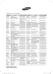
Troubleshooting
Detection of errors
X If an error occurs during the operation, an LED flickers and the operation is stopped except the LED.
X If you re-operate the air conditioner, it operates normally at first, then detect an error again.
LED Display on the receiver & display unit
LED Display
26
Troubleshooting(Cont.)
OOn
Flickering X Off
X If you turn off the air conditioner when the LED is flickering, the LED is also turned off.
X If you re-operate the air conditioner, it operates normally at first, then detect an error again.
X When E108 error occurs, change the address and reset the system.Ex.) When address of the indoor
unit #1 and #2 are set as 5, address of the indoor unit #1 will become 5 and indoor unit #2 will
display E108, A002.
Abnormal condition
Error on indoor temperature sensor (Short or Open)
E121
1. Error on Eva-in sensor (Short or Open)
2. Error on Eva-out sensor (Short or Open)
3. Discharge sensor error (Short or Open)
E122
E123
E126
Indoor fan error
E154
1. Error on outdoor temperature sensor (Short or Open)
2. Error on cond sensor
3. Error on discharge sensor
Other outdoor unit sensor error that is not on the above list
E221
E237
E251
1. When there is no communication between the indoor∙outdoor units for 2 minutes
2. Communication error received from the outdoor unit
3. 3 miniute tracking error on outdoor unit
4. Communication error after tracking due to unmatching number of installed units
5. Error due to repeated communication address
6. Communication address not confirmed
Other outdoor unit communication error that is not on the above list
E101
E102
E202
E201
E108
E109
Self diagnosis error display
1. Error due to opened EEV (2nd detection)
2. Error due to closed EEV (2nd detection)
3. Eva in sensor is detached
4. Eva out sensor is detached
5. Thermal fuse error (Open)
LED Display
Error
code
E151
E152
E128
E129
E198
1. COND mid sensor is detached
2. Refrigerant leakage (2nd detection)
3. Abnomally high temperature on Cond (2nd detection)
4. Low pressure s/w (2nd detection)
5. Abnomally high temperature on discharged air on outdoor unit
(2nd detection)
6. Indoor operation stop due to unconfirmed error on outdoor unit
7. Error due to reverse phase detection
8. Comp stop due to freeze detection (6th detection)
9. High pressure sensor is detached
10. Low pressure sensor is detached
11. Outdoor unit copression ration error
12. Outdoor sump down_1 prevetion control
13. Compressor down due to low pressure sensor prevention control_1
14. Simultaneous opening of cooling/heating MCU SOL valve
(1st detection)
15. Simultaneous opening of cooling/heating MCU SOL valve
(2nd detection)
Other outdoor unit self-diagnosis error that is not on the above list
E241
E554
E450
E451
E416
EEPROM error
E162
EEPROM option error
E163
Error due to incompatible indoor unit
E164
E559
E425
E403
E301
E306
E428
E413
E410
E180
O
O
E181
O
27
"EEE Yönetmeliğine Uygundur"
"This EEE is compliant with RoHS"
Wall-mounted Type Series
Air Conditioner
installation manual
imagine the possibilities
Thank you for purchasing this Samsung product.
To receive more complete service, please
register your product at
www.samsung.com/register
EN DB68-03632A-1