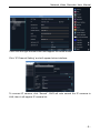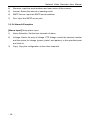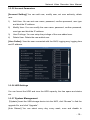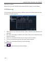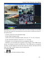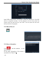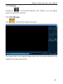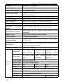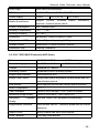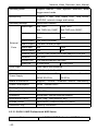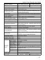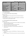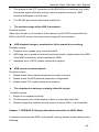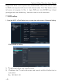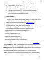
1
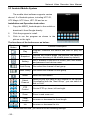
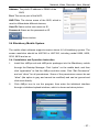
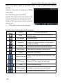
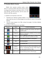
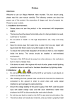
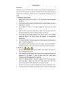
Preface Attentions: Welcome to use our network video recorder. For your secure using, please read this user manual carefully. The following contents are about the proper use of the product, the prevention of danger and loss of property etc. Please be sure to abide. 1. Installation Environment: Please place and use this product in the environment with temperature 0℃-50℃; The device should be placed horizontally when it is being installed and used, avoid lean or inversion; Do not place or install it in the high temperature, wet, dusty and sooty places. Keep the device away from water drop or plash. Don’t put any object with liquid inside like flower vase or any other object on the device. To ensure the normal heat dissipation of the device, there is a fan installed inside the device. The device should be installed in well-ventilated environment; The back of the DVR should be away from other devices or the wall above 6cm in order to release heat; If the device is used in the regions with much thunder, please install lightning protection device to avoid host or hardware breakdown by lightning stroke. 2. Attentions: Do not touch the power switch and the NVR by wet hands or wet objects, in order to avoid electric shock; After installing the host, please make sure that the host and the chassis are connected to the ground in order to avoid video and audio signal interference and damaged by static electricity; Ensure the voltage stability of the power supply of the NVR. Use the power input with stable voltage value and little wave interference rather than shutdown the NVR by disconnecting the main switch directly; Do not drop any liquid or metal on the NVR in case short circuit inside or fire; The device does not include any hard disk, and you need to properly install Network Video Recorder User Manual the hard disk before using it, otherwise, you cannot record and playback the video; The dust on the mainboard will cause short circuit when it is damp. In order to ensure the long-term normal working, you should regularly dedust the mainboard, connectors, chassis, fan and so on by a brush; Do not disconnect the power switch directly when you want to shutdown the NVR. You should use the shutdown button on the panel in order to avoid damage to the hard disk; The device system supports HDD format function. If the HDD has been used, please take note that if it is with FAT 32 format. This NVR only supports HDD with FAT 32 format; Do not open the device when it is connected with electricity;; To ensure the integrity of the recording data, please replace the hard disk when it is damaged (there is disk error record in the log information). 3. Note: The user manual is for reference only. The real object is the standard; The products will be updated at any time. It is subject to update without notice. Please contact our technical department for the latest programs and additional documentation. If there is any doubt or dispute, our company reserves the right of final explanation. This user manual offer references to multi-series products. The specific operation of each product will not be listed one by one. Please contact our technical department when you have any question. -2- Contents Chapter1:ProductInstruction................................................................................5 1.1ProductSummary...................................................................................... 5 1.2MainFunctionsofProduct........................................................................... 5 Chapter2:InstallationInstruction............................................................................ 6 2.1Open-caseInspection................................................................................. 6 2.2HDDInstallation..........................................................................................6 Chapter3:LocalOperationGuide..........................................................................7 3.1Start/ShutdownSystem.............................................................................. 7 3.2SystemLogin.............................................................................................7 3.3MenuOperation......................................................................................... 8 3.3.1StartSetup.......................................................................................... 8 3.3.2HowtoconnectNVRwithIPCameraAtfirst,setIPcameraparameter:...... 8 3.3.3DisplaySetting...................................................................................11 3.3.4PTZSetting....................................................................................... 11 3.3.4.1PTZControl................................................................................12 3.3.4.2PTZSetting................................................................................ 12 3.3.5SystemSetting.................................................................................. 13 3.3.5.1DeviceParameters......................................................................13 3.3.5.2ChannelParameters................................................................... 14 3.3.5.3NetworkParameters....................................................................16 3.3.5.4Alarm&Exception.......................................................................18 3.3.5.5AccountParameters....................................................................19 3.3.5.6HDDSettings..............................................................................19 3.3.5.7SystemManagement..................................................................19 3.3.5.8DeviceLog................................................................................. 20 3.3.6Playback...........................................................................................20 3.3.7RecordBackup................................................................................. 21 3.3.8ManualRecord......................................................................................22 3.3.9AlarmInformation...................................................................................22 3.3.10Capture...........................................................................................23 Network Video Recorder User Manual 3.3.11FileManager................................................................................... 23 Chapter4:NetworkOperatingInstruction..............................................................24 4.1WEBBrowserOperatingInstruction............................................................24 4.1.1NetworkConnection...........................................................................24 4.1.2AtciveXControlInstallationandUserLoginandLogout...........................24 Chapter5:MobileViewingOperatingInstruction.................................................... 25 5.1ClientSoftwareObtaining.......................................................................... 25 5.2TheParameterSettingsoftheNVRwhichSupportsMobileSurveillance........ 25 5.3AndroidMobileSystem............................................................................. 26 5.4BlackberryMobileSystem......................................................................... 27 5.5SymbianMobileSystem........................................................................... 29 5.6WindowsMobileSystem...........................................................................30 5.7iPhoneMobileSystem.............................................................................. 31 Chapter6:Appendix.......................................................................................... 34 6.1HDDCapacityCalculationMethodforReference......................................... 34 6.2RemoteControlOperation.........................................................................36 6.3TechnicalData......................................................................................... 38 6.3.11.5U720P/1080PEconomicNVRSeries.............................................38 6.3.22U720P/1080PEconomicNVRSeries............................................... 39 6.3.31.5U/2U1080PProfessionalNVRSeries............................................. 41 6.4TroubleShooting...................................................................................... 42 Chapter7:DVR/NVRIEViewingOperationInstructionforADSLMode................... 44 7.1DVRsetting............................................................................................. 44 7.2RouterSetting.......................................................................................... 45 7.3IELoginOperations.................................................................................. 46 Appendix-----FAQofNVR...................................................................................47 -4- Network Video Recorder User Manual Chapter 1: Product Instruction 1.1 Product Summary This device is a video coding and recording product specially designed for the video monitoring field, combining with H.264 video compression, large capacity HDD storage, TCP/IP network, embedded Linux operating system and other various advanced electronic information technologies, realizing high-quality image and low bit rate recording features and favourable system stability. The device meets the standard of GB 20815-2006 “Video Security Surveillance Digital Video Device” issued by the government. This device has functions including recording, playback and monitoring simultaneously, realizing synchronous video and audio, with advanced control technology and powerful network data transmission ability. 1.2 Main Functions of Product The following functional characteristics will be different due to the different series of products and their different hardware versions. Real-time Monitoring Compression Processing Function Recording Function Video Playback and Backup Camera Control Alarm Management and Control Communication Port Network Function -5- Network Video Recorder User Manual Chapter 2: Installation Instruction 2.1 Open-case Inspection When you receive the product, please check all the things according to the NVR packing list in the box. 2.2 HDD Installation Installation Preparation: Need one cross screwdriver. This series of HDD NVR can install 2 to 8 pieces of HDD inside, and the capacity of each HDD can be up to 2TB. HDD Installation Steps: Twist off the screws on the side panel of the case and then open the cover of the chassis. Fix the HDD on the HDD screw whole sites of the baseboard with screws. Connect the HDD data cable and power cable. Cover the case, fix it with screws. -6- Network Video Recorder User Manual Chapter 3: Local Operation Guide 3.1 Start/Shutdown System 3.1.1 Start System Plug power cable, press power switch, the power led will be on and the NVR will start. After booting, the video output default to multi-window output mode. If the booting time is within the record setting time period, the system will auto enable the record function. Notice: Please use the NVR matching power supply instead of any other power supply of any other type or brand. 3.1.2 Shutdown System Click → click Shutdown. (Note: this method is suggested when shutdown device in order to avoid damage to the device from electricity cut-off by accident). Long press the power key on the front panel can shutdown the system(the user should have shutdown authority) Notice: Before changing the HDD operation, you should shutdown the device and cut the power supply first and then operate. 3.1.3 Power Failure Recovery When the NVR is under the recording status, if the system power is cut off or the device is shut down forcefully, after reconnected with the power supply, the NVR will auto-save the video before cutting and auto-recover to the previous status and continue to work. 3.2 System Login After normal booting, single-click or press the OK key on the remote control to pop-up the login dialog box, user input the user name: admin and password blank(default to be blank) in the input box. -7- Network Video Recorder User Manual 3.3 Menu Operation 3.3.1 Start Setup Click , and the interface will display: 1) Shutdown: Click “Shutdown” button, the device will shutdown. 2) Reboot: Click “Reboot” button, the device will reboot. 3) Click “Login” button to login the system. User name: admin, password: blank by default; 4) Lock: Click “[ ] Lock”, the menu will be locked. 3.3.2 How to connect NVR with IP Camera At first, set IP camera parameter: This device supports multi-version Onvif protocols, compatible with main brand IP cameras. Take below brands as example: Before connect the IP camera with NVR, please make sure that the IP addresses of the IP camera and the NVR are in a same network section, and the main stream and sub stream are adjusted to be the suggested values (main stream: 2048k, sub stream: 512k), otherwise, these problems may appear: the NVR cannot search the IP camera, the image cannot be connected, the image is not fluent, the image quality is bad and so on. Connect the NVR with the network cable, and the switch in the LAN. After booting, click and enter the system configure interface to set the network parameters including the IP address, subnet mask, network gateway of the NVR. User can run the command ping through the PC in the LAN to ping the IP of the NVR to see if the NVR has connected with the LAN. -8- Network Video Recorder User Manual Then click the right mouse button and appear the below menu: Click “IP Channel Setting” and will appear below interface: To connect IP camera, click “Search”, NVR will auto search the IP cameras in LAN, then it will appear IP camera list: -9- Network Video Recorder User Manual To connect certain IP camera, please select the IP camera in the below list and double-click it, the NVR will auto fill in the IP, protocol, port of the IP camera in the above input box. Then manually input the user name and password of this IP camera and click save, then the image of the IP camera will appear in the channel. - 10 - Network Video Recorder User Manual You can also manually input the IP camera information instead of auto searching the IP and then click save. Below are some main functions of the NVR: The menu consists of display setting, PTZ, setting, playback, record, alarm, capture and file manager etc. The device enters the real-time monitoring screen after normal booting. There are superposed date, time, and channel name of every channel. Icons of record, 3D positioning and alarm status will appear in the right upper corner. 3.3.3 Display Setting Click , the interface on the right will show: 1) Resolution: select the most appropriate resolution as needed; 2) Language: Different languages for selection (For example: Simplified Chinese, Traditional Chinese and English). 3) Skin: There are original version and blue for selection. 4) Screen mode: there are different screen modes for selection, for example, 1 screen, 4 screens, 9 screens and so on. 5) Rotation Interval: Setup the time interval of rotation. Tick “Enable SEQ” to start rotation. (Note: the rotation function can only be enabled under 1 screen) 3.3.4 PTZ Setting - 11 - Network Video Recorder User Manual 3.3.4.1 PTZ Control Before starting the PTZ control, please firstly confirm the PTZ parameter settings, PTZ protocol and the correct connection of the 485 control line etc. After setting the parameters, select the channel which you want to control in the preview interface, then control the left-handed rotation, right-handed rotation, up regulation, down regulation of the lens; zoom in and zoom out of the focal length; zoom in and zoom out of the focal point; zoom in and zoom out of the iris; setting of the PTZ speed. 3.3.4.2 PTZ Setting 1) Preset setting: first turn the camera to the needed position through the direction buttons of the PTZ control, then select a preset number, and click “Settings” button. “Preset” call: select a preset number which needs to be called, and click “Call” button. 2) Cruise setting: select a cruise number, click “Settings”, as shown in the below interface: In the cruise setup interface, select preset point, cruise time, cruise speed, click “Add” button, then the preset point of the cruise path is added (multi-preset successfully points can be added). Click “Delete” button can delete the preset point of the cruise path. 3) “Cruise” call: select a cruise number click “Call” button. “Cruise” delete: select a cruise number, and click “Delete” button. “Track” setup: select a track number, and click “Set” button, then start the PTZ control operations, and then click “Stop”, and the track is remembered successfully. 4) “Track” call: select a track number, and click “Call” button. - 12 - Network Video Recorder User Manual 3.3.5 System Setting Click , and the below interface will show: 3.3.5.1 Device Parameters [Device Info] Check and modify the basic information of the device. [System Version] Check the basic information of the device system. [RS232] Can set RS232 serial port. [RS485] Can set the RS485 serial port. [DST Setting] Tick “DST” check box, then click the set button to set the start time and end time of DST. - 13 - Network Video Recorder User Manual 3.3.5.2 Channel Parameters [Display Settings] The configuration parameter of every channel can be modified. 1) Camera Name: You can modify the name of the specified channel. 2) Time Format: You can select different time formats for the specified channel. 3) Date Format: You can select different date format for the specified channel. 4) Display Week: Can select different week display status for the specified channel. 5) OSD Position: You can select any position for the OSD of the specified channel. 6) Display Parameters: Can set the brightness, contrast, saturation and hue for the specified channel. 7) Video Format: There are PAL and NTSC for selection. 8) Copy To: Copy the configuration parameters to other channels. [Video Parameters] The setting parameters of every channel can be modified. 1) Encoding Type: Main Stream (Normal), Sub Stream, Main Stream (Event) for selection. 2) Stream Type: Video, Video&Audio for selection. 3) 3)Resolution: There are CIF/QCIF/4CIF/2CIF main stream resolution types for selection.. 4) Bitrate Type: Constant and Variable for selection. 5) Frame Rate: Select different value from the drop-down list, the default value is “Full Frame”. 6) Video Quality: Select different image quality as needed, it is default to “Highest”. 7) Copy To: Copy the configuration parameters to other channels. [Schedule Record] You can set different types of record plan for each channel. 1) Enable Recording: Tick the small box before “Enable Recording” will start recording. 2) All Day Recording: Tick the small box before “All Day Recording” to start all day recording, then you can select schedule recording, motion recording, - 14 - Network Video Recorder User Manual alarm recording, command recording etc. 3) Record Time: You can setup by 8 separate time periods. 4) Advanced Settings: You can set the prerecord time and post record time. 5) Copy To: Copy the configuration parameters to other channels. [Motion Detection] The parameters of each channel can be modified. 1) Area settings: Select the motion detection area, press the left mouse button and drag to the area which you want to set motion detection, click OK. 2) Alarm Schedule: Set the time intervals of alarm. 3) Linkage: Select the linkage way which you need. 4) Copy To: Copy the configuration parameters to other channels. Onvif protocol does not support above function [Video Lost] Can modify the parameters of each channel. 1) “Alarm Schedule”: Set the time intervals of alarm. 2) “Linkage”: Select the linkage way which you need. 3) “Copy To”: Copy the configuration parameters to other channels. Onvif protocol does not support above function [Video Tampering] The parameters of each channel can be modified. 1) Area settings: Select the motion detection area, press the left mouse button and drag to the area which you want to set motion detection, click OK. 2) Alarm Schedule: Set the time intervals of alarm. 3) Linkage: Select the linkage way which you need. 4) Copy To: Copy the configuration parameters to other channels. Onvif protocol does not support above function [Video Mask] The parameters of each channel can be modified. 1) Area settings: Select the motion detection area, press the left mouse button and drag to the area which you want to set motion detection, click OK. 2) Copy To: Copy the configuration parameters to other channels. Onvif protocol does not support above function - 15 - Network Video Recorder User Manual 3.3.5.3 Network Parameters [Network Settings] The network basic parameters of the device can be modified. 1) NIC Type: there are different network card types for selections. 2) IP: enter corresponding numbers to modify the IP address. 3) Obtain Auto: Auto search IP function. When open DHCP, the IP/Subnet Mask/Default Gateway cannot be set; If the current DHCP is valid, then the IP/Subnet Mask/ Default Gateway will show the value obtained by DHCP; if the current DHCP is invalid, IP address etc. will show 0. 4) Device Port: Enter the corresponding device port. 5) Subnet Mask: Enter the corresponding IP subnet mask. 6) Default Gateway: Enter the corresponding gateway address. 7) MAC: Display the MAC address current network port. 8) HTTP Port: It is default to 0. 9) Multicast: Enter the corresponding multicast address. 10) Enable Wi-Fi: Tick the box before “Enable Wi-Fi” and click “Wi-Fi”, and enter the following interface: Click “Refresh”, and find the WiFi router and double click. Then input the ip address, subnet mask, default gateway, DNS server address1 and DNS server address 2. 11) Enable 3G: Tick the box before “Enable 3G”, click “3G” to enter the following interface: a. The access number of the China Unicom is *99# APN address is: 3GNET. - 16 - Network Video Recorder User Manual b. The access number of the China Telecom is #777 APN address is blank. c. The access number of the China Mobile is *99***1# APN address is blank. 12) Advance: DNS Server Address1: The IP address of the DNS server. DNS Server Address2: The standby IP address of the DNS server. Alarm Host IP: Enter the IP address of the alarm host. Alarm Host Port: Enter the port of the alarm host. Enable PPPOE: you can enable the PPPOE service: Input the PPPOE user name. Input the dynamic address of the device. Confirm password. [DDNS Settings] Through the DDNS server, there should be a PC with fixed IP address on the internet and run this DDNS server on this PC. 1) Select DDNS server type (There are IP Server, Dyndns, Peanuthull for selection). 2) Input the server name. 3) Input the port. 4) Input the user name. 5) Input the password. 6) Confirm the password. 7) Input the standby domain name. [NTP Settings] Enable NTP timing. 1) Server Address: Input the IP of the NTP server. 2) NTP Port: This SNTP only supports TCP transmission. It is default to 123. 3) Synchronize every: Input the time interval needed to be adjusted. 4) Select Time Zone: Select the time zone of different places. 5) GMT: You can do fine adjustment of time. [Email Settings] Setup E-mail. 1) Email Address: Input the email address. 2) Password: Input the email password. 3) PWD Confirm: Confirm the password. - 17 - Network Video Recorder User Manual 4) Receiver: Input the email address and user name of the receiver. 5) Interval: Select the interval of sending email. 6) SMTP Server: Input the SMTP server address. 7) Port: Input the SMTP server port. 3.3.5.4 Alarm & Exception [Alarm Input] Setup alarm input. 1) Alarm Schedule: Set the time intervals of alarm. 2) Linkage: Select the way of linkage. PTZ linkage: select the channel number and the action for linkage (preset, patrol, and pattern) to the specified point and click ok. 3) Copy: Copy the configuration to the other channels. - 18 - Network Video Recorder User Manual 3.3.5.5 Account Parameters [Account Setting] You can add user, modify user, set user authority, delete user. 1) Add User: You can set user name, password, confirm password, user type and bind the IP address. 2) Modify User: You can modify the user name, password, confirm password, user type and bind the IP address. 3) User Privilege: You can setup the privilege of the new added user. 4) Delete User: Delete the new added user. [User Online]: View the user connected with the NVR, logging way, logging time and IP address. 3.3.5.6 HDD Settings You can format the HDD and view the HDD capacity, the free space and status etc. 3.3.5.7 System Management 【Update] Insert the USB storage device into the NVR, click “Browse” to find the upgrade file, and click “Upgrade”. [Auto Reboot] You can select every day, every week, once and disable to - 19 - Network Video Recorder User Manual maintain the system. [Stream Info.] You can view the main stream and sub stream of each channel. 3.3.5.8 Device Log You can search the logs according to different types and different date and time, as shown in the above picture. 1. Main Type of Log: There are All Type, Alarm, Exception and Operation for selection. 2. Sub Type: According to different main types, there are corresponding sub types for selection. 3. From: You can select the start time of a log you want to search. 4. To: You can select the end time of a log you want to search. 5. Export: You can export the log you have searched. 3.3.6 Playback Click - 20 - , and will show the below interface: Network Video Recorder User Manual [Search]: Select and tick the channel which you want to search the recording, and it will auto search the recording which meet the search condition as shown in the below picture. 1) Pause: pause the current playback image. 2) Stop: Stop the playing video. 3) Slow: Slow down the playback speed. (there are: 1/2, 1/4, 1/8, 1/16 times) 4) Fast: Accelerate playback. (there are: 2, 4, 8, 16 times) 5) Snapshot: You can capture picture in any playback channel. 6) Backup: You can backup the recording of any channel. Insert USB storage device, click Refresh to detect the USB device. If the USB device is recognized normally, it will be displayed in the list, then select the channel, start time and end time, click “Start”, and the system will auto start backup 3.3.7 Record Backup Click , and below interface will show: - 21 - Network Video Recorder User Manual Insert USB storage device, click Refresh to detect the USB device. If the USB device is recognized normally, it will be displayed in the list, then select the channel, start time and end time, click “Start”, and the system will auto start backup and show the progress. 3.3.8 Manual Record 3.3.9 Alarm Information Click , and the interface right will show: on the All the alarm information of the device is recorded in the “Alarm” list. - 22 - Network Video Recorder User Manual 3.3.10 Capture Single-click on the preview channel, click “Capture”, you can capture picture on any preview channel. 3.3.11 File Manager Click , and the below interface will show: The backup files in the external storage device and the capture pictures will be displayed in the document list bar. - 23 - Network Video Recorder User Manual Chapter 4: Network Operating Instruction 4.1 WEB Browser Operating Instruction 4.1.1 Network Connection Confirm the NVR correct access to the network. Set the IP address, subnet mask and gateway for the computer server and NVR. Please allocate IP address in the same network segment if there is no router device in the network. If there is router device, you just need to set corresponding gateway and subnet mask. For the network setting, please refer to [Settings]>[Network Parameters]. Please make sure that the IP address setting is correct. When the IP address setting is complete, you can use the system own ping tool to check if the NVR is connected to the network correctly. 4.1.2 AtciveX Control Installation and User Login and Logout When the NVR accesses to the network correctly, you can login and visit it through IE browser You can download and install IE ActiveX from NVR through the Internet. Then input the IP address of the NVR in the IE browser, port number 5050, user name and password, then the below interface will pop-up: When Login successfully, then shows: More detail Network operation ways, please goes to the Host Side. - 24 - Network Video Recorder User Manual Chapter 5: Mobile Viewing Operating Instruction This operation guide is about how to install and use the mobile softwares in the mobile phones with Android, Blackberry, windows mobile, iPhone, Symbian systems. 5.1 Client Software Obtaining You can obtain the mobile surveillance client software from the CD or our technical department. The corresponding client software of each system is as below: MEYE_SB_S60_3rd.sisx: mobile surveillance client of the 3rd version of Symbian S60 system; MEYE_SB_S60_5rd.sisx: mobile surveillance client of the 5th version of Symbian S60 system; MEYE_WM.cab: mobile surveillance client of Window system; MEYE_Android.apk: mobile surveillance client of Android system; MEYE_RIM.rar: mobile surveillance client of BlackBerry system; Note: iPhone uses TMeye+, downloaded from appstore. 5.2 The Parameter Settings of the NVR which Supports Mobile Surveillance Resolution: CIF or QCIF; Frame Rate: 5-10fps; Stream Type: Limited Stream: 64-256Kb/S Note: you can adjust the settings according to the performance and network condition. Mobile phone with higher performance and network condition will display better effect. If the network condition is not good, you can reduce the frame rate to ensure the fluency. - 25 - Network Video Recorder User Manual 5.3 Android Mobile System The mobile client software supports version above 1.5 of Android system, including HTC G1, HTC Magic, HTC Hero, HTC G5 and so on. Installation and Operation Instruction 1. Copy the MEYE_Android.apk to the mobile or download it from Google directly. 2. Click the program to install. 3. Click to run the program as shown in the picture on the right: The functions of the buttons are as below: Function Button Name Function Description Play Program connects the device and start to play the video Snapshot Capture the current image (the pictures are saved in the picture directory of the mobile phone by default) Setting Set IP address of the NVR or DDNS, port, user name, and password and device name. Last Group Can select the channel of last group Next Group Can select the channel of next group About Select Channel Select to play the video of any channel of the device. Coordinating with the ”Next Group”, you can switch to 8ch or 16ch. PTZ Control Control PTZ up, down, left and right. Zoom Zoom in and zoom out Focal Length Increase or decrease the focal length Iris 4. About the information. Increase or decrease the iris Use for the first time, you need to do the following settings: - 26 - Network Video Recorder User Manual Address: The public IP address or DDNS of the NVR; Port: The server port of the NVR; NVR Title: The device name of the NVR, which is used to differentiate different devices; User ID: Same as the user name on IE; Password: Same as the password on IE. : Return button. 5.4 Blackberry Mobile System The mobile client software supports version above 4.6 of blackberry system. The screen resolution should be 480*360 or 480*320, including model 8900, 9000, 9700, 9630 and so on. 5.4.1 Installation and Operation Instruction 1. Install the vMEye.cod and vMEye.alx packages into the Blackberry mobile through the Desktop Manager. Click “option” on the mobile desk, and then click “application” to find the vMEye and then enter. Click “Edit Permission” and set “allow” for all permissions. Some of the permissions cannot be set “allow” (the option is grey and cannot be modified) and can be ignored and click save directly. 2. Click vMEye icon to run the program, then enter the initialized interface through a initialized splash interface, which is shown as below picture: - 27 - Network Video Recorder User Manual Name: The device name of the NVR, which is used to differentiate different devices; Address: The public IP address or DDNS of the NVR; Port: The server port of the NVR; User ID: The same as the user name on IE; Password: The same as the password on IE. Network Type: Select the network type you want to use. 3. Click Login to enter the main interface: The functions of the buttons are as below: Function Name Function Description Button Program connects the device and start to Play play the video Full Screen Snapshot Setting Next Group About Select Channel PTZ Control Zoom Focal Length Iris - 28 - Full screen play Capture the current image (the pictures are saved in the picture directory of the mobile phone by default) Set IP address of the NVR or DDNS, port, user name, password and device name. Can select the channel of next group About the information Select to play the video of any channel of the device Control PTZ up, down, left and right Zoom in and zoom out Increase or decrease the focal length Increase or decrease the iris Network Video Recorder User Manual 5.5 Symbian Mobile System Mobile client supports symbian system version above 9.1 (namely symbian 3rd and 5th version mobile), including all the 3rd version like Nokia 6120c, e71,5800 with 240*320, 320*240 resolution, the 5th version with 360*640, 640*360 resolution. ☆ Installation and Operation Instruction 1. Download and Install the package file(sisx) in the phone and then you will ind the program icon and find the vmeye in the specified directory. 2. Click the vmeye program icon. After running the program, the below initialized interface will appear: The functions of the buttons are as below: Function Button Name Function Description Play Program connects the device and start to play the video Snapshot Capture the current image (the pictures are saved in the picture directory of the mobile phone by default) Setting Set IP address of the NVR or DDNS, port, user name, password and device name. Next Group Can select the channel of next group Exit Exit the program Full Screen Full screen view Select Channel PTZ Control Select to play the video of any channel of the device. Coordinating with the ”Next Group”, you can switch to 8ch or 16ch. Control PTZ up, down, left and right - 29 - Network Video Recorder User Manual Zoom in and zoom out, increase and Zoom, Focal decrease focal length and iris. The above Length, Iris prompting bar will prompt the function of the selected button. Use for the first time or need to modify the parameters, please click Setting button to enter the parameter setting interface, which as shown in the below picture: IP: The public IP address or DDNS of the NVR; Port: The server port of the NVR; User Name: The same as the user name on IE; Password: The same as the password on IE. Allias: Give a name to the device and it will appear on the playing page. 5.6 Windows Mobile System Mobile client supports windows system version above 2003. It only supports screen touch version currently. 1. Copy the MEYE_WM.cab to the mobile and install it. Click the corresponding program icon to open as shown in the picture on the right. Function Button Name Function Description Connect and Play Program connects the device and start to play the video Setting Set IP address of the NVR or DDNS, port, user name, password and device name. Disconnect - 30 - Program disconnects the video Network Video Recorder User Manual Select Channel PTZ Control Zoom Focal Length Iris Snapshot Select to play the video of any channel of the device Control PTZ up, down, left and right Zoom in and zoom out Increase or decrease the focal length Increase or decrease the iris Capture the current image (the pictures are saved in the picture directory of the mobile phone by default) The functions of the buttons are as below: 2. Use for the first time or need to modify the parameters, please click button to enter the parameter setting interface, as shown in the below picture: Username: The same as the user name on IE; Password: The same as the password on IE. Server: The public IP address or DDNS of the NVR; Port: The server port of the NVR; Notes: The description of the NVR, which is used to differentiate different devices; 3. After successful setting, press [OK] button to enter the connection interface. The image will appear if connected successfully. 5.7 iPhone Mobile System Mobile client supports iphone system version iOS 3.0 or higher version, including iPhone,iPod touch and so on. - 31 - Network Video Recorder User Manual Installation and Operation Instruction 1. Run the App Store of iPhone, switch to search page, input TMeye+, in the search bar, and find the application program package, click install. After finish installation, the program icons will appear as shown in the below picture: 2. Click TMeye+, icon, the above initialized interface will appear. The functions of the buttons are as below: Function Button Name Last Group Program connects the device and start to play the video Capture the current image (the pictures are saved in the picture directory of the mobile phone by default) Set IP address of the NVR or DDNS, port, user name, password and device name. Can select the channel of last group Next Group Can select the channel of next group Play Snapshot Setting About Select Channel PTZ Control - 32 - Function Description About the information Select to play the video of any channel of the device. Coordinating with the”Next Group”, you can switch to 8ch Control PTZ up, down, left and right Network Video Recorder User Manual Zoom Focal Length Iris 3. Zoom in and zoom out Increase or decrease the focal length Increase or decrease the iris Use for the first time or need to modify the parameters, please click Setting button to enter the parameter setting interface, which as shown in the below picture: Alias: The name of the NVR, which is used to differentiate different devices; Address: The public IP address or DDNS of the NVR; Port: The server port of the NVR; User ID: The same as the user name on IE; Password: The same as the password on IE. : Return button. - 33 - Network Video Recorder User Manual Chapter 6: Appendix 6.1 HDD Capacity Calculation Method for Reference Install the network video recorder for the first time, please make sure whether the HDD is installed inside the host. 6.1.1 The Capacity of the HDD The digital video recorder requires a single HDD with above 500GB capacity. In order to obtain better stability, we recommend the HDD with 500G ~ 2TB capacity. 6.1.2 The Selection of the Total Capacity Calculate the total capacity of a NVR requires according to the recording requirement(recording type, recording file storage time). Calculation method: Step 1 : Calculate the storage capacity qi of a channel requires per hour according to the formula(1), Unit: MByte. qi di ÷ 8 × 3600 ÷ 1024(1) The Recording File The Recording File Size in One Hour Size in One Day 256K 112M 2.6G 320K 140M 3.3G 512K 225M 5.3G Bit Stream Size di - = 768K 337M 7.9G 1.00M 439M 10.3G 1.50M 659M 15.4G 2.00M 878M 20.6G bit rate,Unit Kbit/s The following table shows the recording file size of the common bit rate under constant bit rate within one hour and one day for one channel. - 34 - Network Video Recorder User Manual The second step: after confirming the time requirement of recording, calculate the storage capacity i m one channel requires according to formula(2), unit: MByte. mi = qi × hi × Di (2) hi - recording time of each day(Hour) Di - number of days of recording storage For example: the HDD capacity for recording one month for 1 channel 1.50M bit stream. Unit GB. mi = 659×24×31=490296MB= 478GB The third step: the total capacity (accumulating) qT for 16 channels timing recording for a whole day. Unit: GB qt = q16 = mi ×16 =7648GB If select 500G HDD, 16 pieces of HDD will be required to full record. User selects appropriate HDD according to the capacity. The fourth step: calculate the total capacity(accumulating) needed for allchannels alarm recording(including motion detection). Unit: GB qt ×a% a%-alarm occurring rate. Alarm occurring rate: Tn T1 + T2 + T3 +…… Tn )/n T24 (n=1,2,3…) - The alarm time of the Nth day(the time difference of larm end and alarm start) Unit: h qt - T24 - 24h the needed HDD capacity of T channels timing For example: if the alarm occurring rate a% for a month is 50%, then the alarm - 35 - Network Video Recorder User Manual recording capacity of 16 channels in one month is: Unit:GB qt ×a%= q16 ×50%=7648×50%=3.7GB 6.2 Remote Control Operation Numb Icon Description Number Icon er 1 REC Descriptio n Last Record Key 13 I◄◄ 2 Power On/Off 14 ► PLAY Video 3 Key Window 15 I► Frame Playback Frame 4 Devide Key Window 16 Forward ▲ Forward Up 17 ▼ Down 18 ◄ Left 19 ► Right Devide Key Auxiliary Section 5 FN 6 STATUS/DEV 7 PTZ 8 II 9 OSD Menu Key 21 ESC Exit Key 10 ►►I Next Section 22 MENU Menu Key 11 ►► 23 1-16 12 ◄◄ Function Key Device Code Key PTZ Control Key Playback Pause Key Fast Forward Key 20 Enter Key Channel 1-16 Fast Backward Note: When there are devices in Key a same place, the remote control should choose a device first according to the device number. Therefore, you should define one unique device number for each machine; otherwise, the remote control operation may simultaneously affect the devices which are with the same device number. - 36 - Network Video Recorder User Manual 6.2.1 Remote Control Battery Put into 2 pieces of No.7 batteries. Make sure that the positive and negative polarity correspond with each other rightly. 6.2.2 Code Corresponding Operation of the Remote Control Press the [STATUS]/[DEV] button on the remote control, then input the NVR device number (default device number is “255”. It can be modified under Management Tools System Parameter). The maximum device number which can be set is 255. Input the 3-digit device number on the remote control, adding 0 in front if the number is not up to 3-digit, then press the [ENTER] button. 6.2.3 Turn on by Remote Control When the device is under the status of being selected by the remote control, keep pressing [POWER] button on the remote control can turn off the device so that it will be under standby mode. When the device is under the standby mode status of being selected, flicking on the [POWER] button can turn on the device and enter normal working condition. 6.2.4 Disable Remote Control Operation When the device is under the status of being selected by the remote control, press the [DEV] button and the remote control will terminate the control on the NVR. 6.2.5 Abnormity Check of Remote Control Check the positive and negative polarity of the batteries. Check whether the power of the batteries has run out. Check whether the remote control sensor is blocked. Check whether there is fluorescent light being used in the nearby. 6.3 Technical Data 6.3.1 1.5U 720P/1080P Economic NVR Series Series 1.5U 720P/1080P Economic NVR Series Product Category 1.5U 4ch NVR 1.5U 9ch NVR 1.5U 16ch NVR - 37 - Network Video Recorder User Manual Chassis Standard 1.5U Chassis Operating System Embedded LINUX operating system Image Code Standard H.264/MPEG4 AVC Image Code Control Image,code,quality,adjustable,variable,bitrate,and,const ant1bitrate,optional Dual Stream Each channel can set main stream and sub stream Audio Compression G.711 Video Standard 1080P(1920×1080)fps / 720P(1280×720)30fps Monitoring Image Quality 1080P(1920×1080) / 720P(1280×720) Recording Playback Quality Image Motion Detection Any 4ch 1080P/720P playback simultaneously Each screen can set detection areas and set 6-level sensitivity Region Cover Every channel can set 4 cover regions Voice Talkback Two-way voice talkback Recording Mode Backup Way Recording Storage Video Input Audio Input External Ports - 38 - Support manual , auto, dynamic detection, alarm trigger record mode Support U disk, USB mobile HDD, USB DVD-RW, network storage and backup Local HDD, network 4ch 720P/ 3ch 720P+ 1ch 1080P 9ch 720P/ 4ch 16ch720P /8ch 720P+2ch 1080P 720P+4ch 1080P /4ch 1080P / 9ch 1080P 4ch network audio 9/6/4ch network 16/12/9ch network input audio input audio input Video Output 1ch VGA+1ch HDMI Audio Output 1ch BNC auxiliary output Alarm Input 4ch 9ch 16ch Alarm 1ch 1ch 4ch Network Port 1 RJ45,10M/100M/1000M self-adaptive LAN port Wireless 3G, WIFI RS485 Port Full duplex standard 485 port USB Port 2 USB ports 3 USB ports Network Video Recorder User Manual Local Login User name and password HDD Port 2 SATA HDD port/1 SATA+1 E-SATA Power Supply 12V4A Mobile Surveillance Support DC12V3.3A (iPhone, Windows DC12V5A Mobile, BlackBerry, Symbian, Android) smart phone Power Consumption ≤25(without HDD) Working Temperature -10℃~+55℃ Working Humidity 10%-90% Dimension Equipment: 350mm×240mm×70mm, Wight(without HDD) N.W.: 1.7Kg;with packing:2.89Kg Outside Carton 5pcs/carton. 675mm×425mm×385mm; Installation Way Desktop installation 6.3.2 2U 720P/1080P Economic NVR Series Series 2U 720P/1080P Economic NVR Series Product Category 2U 720P 9ch NVR Chassis Standard 2U Chassis Operating System Embedded LINUX operating system Image Code Standard H.264/MPEG4 AVC Image Code Control Image,code,quality,adjustable,variable,bitrate,and,con Dual Stream stant1bitrate,optional Each channel can set main stream and sub stream Audio Compression G.711 Video Standard 1080P(1920×1080)fps / 720P(1280×720)30fps 2U 720P 16ch NVR Monitoring Image Quality 1080P(1920×1080) / 720P(1280×720) Recording Any 4ch 1080P/720P playback simultaneously Playback Quality Image Motion Detection Each screen can set detection areas and set 6-level sensitivity Region Cover Every channel can set 4 cover regions Voice Talkback Two-way voice talkback - 39 - Network Video Recorder User Manual Recording Mode Support manual , auto, dynamic detection, alarm trigger record mode Backup Way Support U disk, USB mobile HDD, USB burner, DVD-RW, network storage and backup Recording Storage Video Input Audio Input External Ports Local HDD, network 9ch 720P/ 16ch 720P/ 4ch 720P+2ch 1080P 8ch 720P+4ch 1080P/ 9/6/4ch network audio 16/12/9ch input input network audio Video Output 1ch VGA+1ch HDMI Audio Output 1ch BNC auxiliary output Alarm Input 9ch 16ch Alarm Output 1ch 4ch Network Port 1 RJ45,10M/100M/1000M self-adaptive LAN port Wireless 3G, WIFI RS485 Port Full duplex standard 485 port USB Port 2 USB ports 3 USB ports Local Login User name and password HDD Port 8 SATA+2 E-SATA HDD port Power Supply AC110-240V ~ ATX AC110-240V ~ ATX 300W 200W 50-60 Hz 50-60 Hz Mobile Surveillance Support( iPhone, Windows Mobile, BlackBerry, Power Consumption ≤30W(without HDD) Working Temperature -10℃〜+ 55℃ Working Humidity 10%-90% Dimension Equipment: 440mm×450mm×90mm, Wight(without HDD) N.W.: 6Kg;with packing: 9Kg Outside Carton 2pcs/carton. 555mm×545mm×470mm; Installation Way Desktop installation 6.3.3 1.5U/2U 1080P Professional NVR Series Series - 40 - 1.5U/2U 1080P Professional NVR Series Network Video Recorder User Manual Product Category 1.5U 1080P 16ch NVR 2U 1080P 16ch NVR Chassis Standard 1.5U Chassis Standard 1.5U Chassis Operating System Embedded LINUX operating system Image Code Standard H.264/MPEG4 AVC Image Code Control Image,code,quality,adjustable,variable,bitrate,and, constant1bitrate,optional Dual Stream Each channel can set main stream and sub stream Audio Compression G.711 Video Standard 1080P(1920×1080) 30frame/second Monitoring Image Quality 1080P(1920×1080) Recording Playback Quality 16ch 1080P Playback Channel 4ch Image Motion Detection Each screen can set detection areas and set 6-level sensitivity Region Cover Every channel can set 4 cover regions Voice Talkback Two-way voice talkback Recording Mode Backup Way Support manual , auto, dynamic detection, alarm trigger record mode Support U disk, USB mobile HDD, USB burner, DVD-RW, network storage and backup Recording Storage Local HDD, network Network Video Input 16ch Network Audio Input 16ch External Ports Video Output 1ch VGA+1chHDMI Audio Output 1ch BNC Alarm Input 16ch Alarm Output 4ch Network Port 1 RJ45,10M/100M/1000M self-adaptive LAN port Wireless Port Support 3G, WIFI RS485 Port Full duplex standard 485 port USB Port 3 USB port Local Login User name and password HDD Port 2 SATA/1 SATA+1 8 SATA +2 E-SATA - 41 - Network Video Recorder User Manual Power Supply DC12V5A Mobile Surveillance Support AC110-240V ~ ATX Power Consumption ≤20W(without HDD) (iPhone , Windows Mobile ≤40W(without HDD) Working Temperature -10 C〜+ 55 C Working Humidity 10%-90% Dimension Equipment: Equipment: Wight(without HDD) N.W.: 1.7Kg, with N.W.: 6.58Kg, with Outside Carton 5pcs/catton, 2pcs/carton, Installation Way Desktop installation o , 0 6.4 Trouble Shooting The device fails to start or keeps restarting. Possible causes: 1. NVR is upgraded with wrong program which has caused the damage of system software. 2. The main board is defective; please contact the supplier for maintenance. 3. HDD is defective, please replace the HDD. Fail to operate the device by remote control Possible causes: 1. Check if the batteries in the remote control are installed correctly, especially the positive and negative polarity. 2. Check if the batteries in the remote control have power. 3. Check if the remote control window is covered. 4. Check if the remote address of the NVR matches the address of the remote control. Fail to control PTZ Possible causes: 1. Incorrect cable connection of the RS-485 port, A, B ports are connected oppositely. 2. Incorrect settings of PTZ decoder type, protocol, baud rate and address bit. - 42 - Network Video Recorder User Manual 3. The quantity of the PTZ connected to the RS-485 bus is relatively big, which causes the signal reflection, and you need to parallel connect a 120Ω electrical resistance in the far-end. 4. The RS-485 port of the main board is defective. The preview image of the NVR is scratched. Possible causes: Video input format is not matched. If the camera is with NTSC format while the NVR is with PAL format, then the preview image will be scratched. NVR playback image is scratched or fail to search the recording. Possible causes: 1. Program error; please try to reboot the NVR. 2. HDD data error caused by bad track and bad clusters, please detect the HDD. If the HDD is defective, please replace the HDD. 3. Hardware error of NVR, please contact the supplier. NVR cannot connect network. Possible causes: 1. Please check if the network physical connection is correct. 2. Please check the NVR network parameter configuration. 3. Please check if IP conflict exists in the network. The download or backup recording video fail to play Possible causes: 1. Player is not installed correctly. 2. The file system error of the backup U disk or removable hard disk. 3. Graphics speed up software whose version is above DX8.1 is not installed. Chapter 7: DVR/NVR IE Viewing Operation Instruction for ADSL Mode If customer connects with ADSL and need IE viewing, please do the setting as the following: - 43 - Network Video Recorder User Manual Equipments: NVR, 1 set computer that connected with LAN, router, internet cable Let DVR and computer both connect with internet cable. Click “Star” button on the left corner of computer Run Input CMD and click ENTER key- Input ipconfig/all and click ENTER key. Then take note for the IP information 7.1 NVR setting 1. Start the NVR Click Setting icon to enter the setting menuNetwork Setting Click DDNS for setting. 1) The physical address can keep the same; 2) IP address: the IP must be the unique and cannot conflict with other host or workstation Eg:192.168.1.101 - 44 - Network Video Recorder User Manual 3) Default Gateway: be same with the LAN gateway, eg: 192.168.1.1 a) Subnet Mask:255.255.255.0 b) DNS Address: be same with the LAN gateway; c) Device Port: default number is 5050, can change as the necessary; d) http Port: default number is 80, can change as the necessary; e) Cell Phone Port: +3 based on the device port number, eg, if the device port is 5050, then the cell phone port is 5053 7.2 Router Setting As the so many different router brands, take the TP-LINK router as the example, please do the operation as the following: 1. Open IE browser and input the gateway, like: http://192.168.1.1 2. Input the User Name and Password to login the router management TP-LINK default user name: admin, password: admin, 3. Click the “Forwarding Rules” of tool bar at the left side, some router named it by Port Mapping, click Virtual Serverclick Adding New Items Add the following DVR IP address to there and save it. HTTP Port: default number 80 Device Port: default number 5050 Default Port: default number 5051 Default Port: default number 5052 Cell Phone Port: default number 5053 After finish it and click the item “ All entries effect” Now take 3322 as the example, bound the dynamic IP address www.3322.org to fixed domain name. Enter 3322 website and input the application information. Take note the domain name after applying successfully. Note: domain name, user name and password need to add on the DDNS setting of DVR network setting. Now input the applied domain in the IE browser, you can login the NVR. Note: If you fail to login in, please try again by adding colon + http port number. - 45 - Network Video Recorder User Manual 7.3 IE Login Operations Open IE browser and input the domain name, then it pop out the following information: Downloading activx, please wait or click here. Once the download has completed, please close IE browser first before unzipping the installation package. After installation finished, then open the IE browser and input the domain name, login with port number, user name and password. The default user name is admin and no password. Then you will see the DVR monitoring image. If you think the above operation is too difficult, we suggest you use www.aedvr.com free domain name + Client server of UPnP automatic DNS Do the following operation after the setting of 7.1: 1. Write down the device series number: (SettingDevice ParameterDevice InfoDevice Series No) 2. Enter Network SettingClick Advance Select Enable manage host & Enable UPnP. 3. Manage host address: www.aedvr.com Port: 5050, save and login out 4. Login www.aedvr.com by IE browser, Port: 81, User name: admin, no password. Input device series number, user name and password, click OK, then can see DVR monitoring image. This method no need router setting and no need login domain name, it’s very easy and stable. Appendix-----FAQ of NVR 1. Q: Why Motion Detection Alarm, Mask Alarm, Video Alarm configuration setting is correct but fail to work - 46 - Network Video Recorder User Manual A: The ONVIF protocols of IPC that connected with NVR do not support these functions now. 2. Q: Why fail to search IPC? A: Maybe the NVR or IPC doesn’t connect with the internet properly, please test the internet connection by run PING command, and also please check whether there is IP conflict. 3. Q: Need long time waiting for the image showing A: Different brands or different models of IPC have time difference for the imaging showing, but normally the waiting time should less than one minute. But it’s true that some may be longer than one minute. 4. Q: After saving, no imaging comes out. A: Maybe the user name or password is mistake; also maybe the private protocol of IPC caused the compatible problem. Please try again by the IPC that support i8 protocol or the standard ONVIF protocol. 5. Q: Some channel has the recording information and the image comes out after double clicking, but the image fails to show at the multi-channel preview mode. A: Right click the image channel to bring out the main menu, then go to IP Channel Setting, select Sub-stream instead of Main Stream for the Mode item. Then save the configuration. If there still no image come out at multi-channel preview mode, please adjust the sub-stream less than 1M. - 47 -