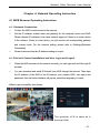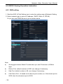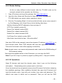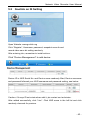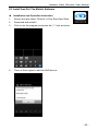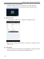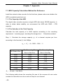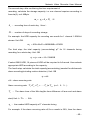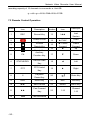
1
Attentions: Welcome to use our network video recorder. For your secure using, please read this user manual carefully. The following contents are about the proper use of the product, the prevention of danger and loss of property etc. Please be sure to abide. 1. Installation Environment: Please place and use this product in the environment with temperature 0℃-50℃; The device should be placed horizontally when it is being installed and used, avoid lean or inversion; Do not place or install it in the high temperature, wet, dusty and sooty environment. Keep the device away from water drop or plash. Don’t put any object with liquid inside, like flower vase or any other object on the device. To ensure the normal heat dissipation of the device, there is a fan built-in. The device should be installed in well-ventilated environment; The back of the DVR should be away from other devices or the wall (above 6cm) to dissipate heat. If the device is used in the regions with much thunder, please install lightning protection device to avoid host or hardware damaged by lightning stroke. 2. Attentions: Do not touch the power switch and the NVR by wet hands or wet objects, to avoid electric shock; After installing the host, please make sure that the host and the chassis are connected to the ground to avoid video and audio signal interference and damaged by static electricity; Ensure the voltage stability of the power supply of the NVR. Use the power input with stable voltage value and little wave interference rather than shutdown the NVR by disconnecting the main switch directly; Do not drop any liquid or metal on the NVR in case short circuit inside or fire; The device does not include any hard disk, and you need to properly install the hard disk before using it, otherwise, you cannot record and playback the Network Video Recorder User Manual video. The dust on the mainboard will cause short circuit when it is damp. In order to ensure the long-term normal working, you should regularly dedust the mainboard, connectors, chassis and fan by brush. Do not disconnect the power switch directly when you want to shutdown the NVR. You should use the shutdown button on the panel to avoid the hard disk broken. The device system supports HDD. If the HDD has been used, please take note that with FAT32 format. This NVR only supports HDD with FAT32 format. Do not open the device when it is connected with electricity.; To ensure the integrity of the recording data, please replace the hard disk when it is damaged (there is disk error record in the log information). 3. Note: The user manual is for reference only. The real object is the standard. The products will be updated at any time. It is subject to update without notice. Please contact our technical department for the latest firmware and additional document. If there is any doubt or dispute, our company reserves the right of final explanation. This user manual offer references to multi-series products. The specific operation of each product will not be listed one by one. Please contact our technical department when you have any question. -2- Contents Chapter 1: Product Instruction ........................................................................................................... 5 1.1 Product Summary.................................................................................................................... 5 1.2 Main Functions of Product..................................................................................................... 5 Chapter 2: Installation Instruction....................................................................................................... 6 2.1 Accessories................................................................................................................................ 6 2.2 HDD Installation......................................................................................................................... 6 Chapter 3: Local Operation Guide................................................................................................... 7 3.1 Start/Shutdown System.......................................................................................................... 7 3.1.1 Start NVR........................................................................................................................... 7 3.1.2 Shutdown NVR................................................................................................................ 7 3.1.3 Power Failure Recovery................................................................................................ 7 3.2 System Login............................................................................................................................. 8 3.3 Menu Operation........................................................................................................................ 8 3.3.1 Setup................................................................................................................................... 8 3.3.2 User Guide ........................................................................................................................ 8 3.3.3 How to connect NVR with IP Camera ...................................................................... 9 3.3.4 Preview.............................................................................................................................12 3.3.4.1 Drag And Drop the Image..................................................................................14 3.3.4.2 Drag To Change Channel Sequence ...........................................................14 3.3.4.3 Digital Zooming......................................................................................................14 3.3.5 Display Setting................................................................................................................14 3.3.6 PTZ Setting......................................................................................................................14 3.3.6.1 PTZ Control............................................................................................................14 3.3.6.2 PTZ Setting.............................................................................................................15 3.3.7 System Setting ...............................................................................................................15 3.3.7.1 Device Parameters..............................................................................................16 3.3.7.2 Channel Parameters...........................................................................................17 3.3.7.3 Network Parameters ...........................................................................................21 3.3.7.4 Alarm & Exception................................................................................................23 3.3.7.5 Account Parameters............................................................................................24 Network Video Recorder User Manual 3.3.7.6 System Management.........................................................................................25 3.3.8 Playback........................................................................................................................27 3.3.9 Record Backup..............................................................................................................28 3.3.10 Record............................................................................................................................29 3.3.11 Alarm Information........................................................................................................29 3.3.12 Capture...........................................................................................................................29 3.3.13 File Manager.................................................................................................................30 Chapter 4: Network Operating Instruction....................................................................................31 4.1 WEB Browser Operating Instruction.................................................................................31 4.1.1 Network Connection.....................................................................................................31 4.1.2 AtciveX Control Installation and User Login and Logout....................................31 4.2 NVR IE Viewing Operation Instruction .............................................................................32 4.2.1 NVR Setting ....................................................................................................................31 4.2.2 Router Setting.................................................................................................................31 4.2.3 Network Connection.....................................................................................................31 4.2.4 Web Browser System..................................................................................................31 Chapter 5: P2P Cloud Function......................................................................................................44 5.1 Goolink Mobile Client Setting...............................................................................................44 5.2 Goolink On IE Setting............................................................................................................44 Chapter 6: Mobile Viewing Operating Instruction.......................................................................44 6.1 Client Software Obtaining.....................................................................................................44 6.2 The Parameter Settings of the NVR which Supports Mobile Surveillance ...........44 6.3 Install And Set The Mobile Software.................................................................................45 Chapter 7: Appendix ..........................................................................................................................48 7.1 HDD Capacity Calculation Method for Reference........................................................48 7.2 Remote Control Operation ..................................................................................................50 Chapter 8: Trouble Shooting............................................................................................................51 -4- Network Video Recorder User Manual Chapter 1: Product Instruction 1.1 Product Summary This device is a video coding and recording product specially designed for the video monitoring field, combining with H.264 video compression, large capacity HDD storage, TCP/IP network, embedded Linux operating system and other various advanced electronic information technologies, realizing high-quality image and low bit rate recording features and favourable system stability. The device meets the standard of GB 20815-2006 “Video Security Surveillance Digital Video Device” issued by the government. This device has functions including recording, playback and monitoring simultaneously, realizing synchronous video and audio, with advanced control technology and powerful network data transmission ability. 1.2 Main Functions of Product The following functional characteristics will be different due to the different series of products and their different hardware versions. Real-time Monitoring Compression Processing Function Recording Function Video Playback and Backup Camera Control Alarm Management and Control Communication Port Network Function -5- Network Video Recorder User Manual Chapter 2: Installation Instruction 2.1 Accessories When you receive the product, please check all the accessories according to the NVR packing list in the box. 2.2 HDD Installation Installation Preparation: Need one cross screwdriver. This series of HDD NVR can install 2 to 8 pieces of HDD inside, and the capacity of each HDD can be up to 2TB. HDD Installation Steps: Twist off the screws on the side panel of the case and then open the cover. Fix the HDD on the HDD screw whole sites of the baseboard with screws. Connect the HDD data cable and power cable. Cover the case, fix it with screws. -6- Network Video Recorder User Manual Chapter 3: Local Operation Guide 3.1 Start/Shutdown NVR 3.1.1 Start NVR Plug in the power cable, and then press the power switch, the power led will be on and the NVR will start. After booting, the video output default to multi-window output mode. If the booting time is in the record setting time period, the system will auto record. Notice: Please use the NVR matching power supply instead of other power supply of other brand. 3.1.2 Shutdown NVR → click Power off. Click Long press the power key on the front panel can shutdown the system(the user should have shutdown authority) Notice: Before replacing the HDD, you should shutdown the device and cut the power supply first. 3.1.3 Power Failure Recovery When the NVR is under the recording status, if the power is cut off or the device is shutdown forcibly. After reconnected the power supply, the NVR will auto-save the video before cutting and auto-recover to the previous status. -7- Network Video Recorder User Manual 3.2 System Login After normal booting, click or press the OK key on the remote control to pop-up the login window, input the user name: admin and password blank (default to be blank) to login. 3.3 Menu Operation 3.3.1 Setup Click , and it will show: 1) User guide: Click “User guide” button, it will guide you to set the NVR up. 2) Power off: Click “Power off” button, the device will shutdown. 3) Reboot: Click “Reboot” button, the device will reboot. 4) Click “Login” button to login the system. User name: admin, password: blank by default. 5) OnLock: Click “on Lock”, the toolbar on the upper left corner will be locked. 6) Device time: The device time. 3.3.2 User Guide It will show the user guide window after you log in the system, or you can click the right mouse button in the main page Start User Guide. 1) Language: Different languages for selection (For example: Simplified Chinese, Traditional Chinese and English) 2) Display Setting: Video Format: NTSC/PAL can be selected. Resolution:800x600/1024x768/1280x1024/1366x768/1440x900/1920x128 0 can be selected. 3) Network Setting: Insert the IP, subnet mask and default gateway. -8- Network Video Recorder User Manual 3.3.3 How to connect NVR with IP Camera 1. Set NVR: This device supports multi-version Onvif protocols, compatible with marketing main brand IP cameras. Before connect the IP camera with NVR, please make sure that the IP addresses of the IP camera and the NVR are in a same network section, and the main stream and sub stream are adjusted to be the suggested values (main stream: 2048k, sub stream: 512k, otherwise, the NVR maybe cannot search the IP camera, the image cannot be connected, the image is not fluent or the image quality is bad. Connect the NVR to the switch hub in the LAN. After booting, click right buttonsettings or toolbar icon on the upper left corner, and then click “Network Settings” to set the network parameters including the IP address, subnet mask, network gateway of the NVR. Notice: IP address might conflict with each other, please set the gateway correctly, or NVR cannot work. Please ensure all the IP addresses in LAN are unique. Remote port: default is 5050, if there are several NVRs in the LAN, need to change this port for login NVR by IE, CMS. Login NVR by mobile, the port should be +3 based on the device port. -9- Network Video Recorder User Manual HTTP port: default is 80, suggest modifying it. This port for login NVR by IE, input NVR IP address or domain name; need to add colon and HTTP port number. Enable Wi-Fi: use Wi-Fi dongle to connect to internet. Enable 3G: use 3G dongle to connect to internet. If access NVR by IE in WAN, please use static IP or dynamic domain name, the operation is same with LAN. 2. Set IP cameras: Back to the main page, Click right button“IP Channel Setting”Manual, will appear below window: To connect IP cameras, click “Search”, NVR will auto search the IP cameras in LAN, then it will appear IP cameras list: - 10 - Network Video Recorder User Manual A –Area: cameras IP address searching area——click Search to get the camera IP addresses in LAN B- Area: camera IP address modification area——double click IP camera in A area, B area will show camera network data, some cameras can change IP address directly in B area C- Area: cameras channel setting area——according to the selection sequence in A zone, to sort the 1-36 channels image order. Select All to add IP cameras to the all channel by one click. D-Area: camera user name and password filling area——this area is camera network parameter Automatic Search: Back to the main page, click right button“IP Channel Setting”Auto If the IP camera has private protocol with NVR, NVR will assign IP address to the camera automatically. After finish searching, it will connect automatically. Camera IP addresses will be added automatically in the preview channel area. After adding IP camera and click Save, then the image of the IP camera will appear in the channel. - 11 - Network Video Recorder User Manual Below are the main functions of the NVR: The menu consists of display setting, PTZ, setting, playback, record, alarm, capture and file manager etc. The device enters the real-time monitoring screen after normal booting. There are superposed date, time, and channel name of every channel. Icons of record, 3D positioning and alarm status will appear in the right upper corner. 3.3.4 Preview 3.3.4.1 Drag and Drop the Image The preview image location can be drag and drop to different place as necessary, but the channel number will keep the same(ATTN: channel number in red circle as below) Preview image can randomly drag to adjust according to actual management requirement, which makes surveillance management more systematic and friendly. - 12 - Network Video Recorder User Manual 3.3.4.2 Drag to Change Channel Sequence During real video surveillance, it’s very important to have preview channel position of IPC image. Simple image dragging could not meet the need of multi-channel simultaneous playback and it’s frustrating to match channel position respectively when searching. Dragging channel sequence can solve this problem. Back to the main page, Click right button“IP Channel Setting”drag to change channel sequence. Operation is same as 6.3.1. After dragging channel sequence, users are unnecessary to input username and password again, and IPC will reconnect in its new channel position. When dragging, 2 channels exchanged would lose image for a short while till reconnection. Time for reconnection depends on different IPC, which costs about 1 to 60 second. Zoom In 3.3.3.3 Digital Zooming During image preview and playback, roll mouse roller to do digital zooming, it zoom the image as mouse pointer as the center. The max can do 15X zooming. Drag the zoomed image by mouse to see image detail The channel is recording. Light flashing means frame lost or recording lost. - 13 - Network Video Recorder User Manual Please adjust the code stream, for details, please refer to 6.5.2; Magnifying glass: digital zooming, the red number in the middle is magnification figures, click this icon, it can change to PTZ control 3.3.5 Display Setting Click 1) , and it will show: Language: Different languages for selection (For example: Simplified Chinese, Traditional Chinese and English) 2) Auto logout: Set how many minutes to log out system automatically. 3) TV adjust: Set the image location.. 4) Display: Adjust Brightness, Contrast, Saturation, Hue, Transparency. 5) Resolution: select the most appropriate resolution as needed. 6) Rotation Interval: Setup the time interval of rotation. Tick “Enable SEQ” to start rotation. (Note: the rotation function can only be enabled under 1 screen) 3.3.6 PTZ Setting Click will show the below window: 3.3.6.1 PTZ Control Before starting the PTZ control, please confirm the PTZ parameter settings first, PTZ protocol and the correct connection of the RS485 cable. After setting the parameters, select the channel which you want to control in the preview interface, then control the left-handed rotation, right-handed rotation, up regulation, down regulation of the lens; zoom in and zoom out of the focal length; zoom in and zoom out of the focal point; zoom in and zoom out of the iris; setting of the PTZ speed. - 14 - Network Video Recorder User Manual 3.3.6.2 PTZ Setting 1) Preset setting: first turn the camera to the needed position through the direction buttons of the PTZ control, then select a preset number, and click “Settings” button. “Preset” call: select a preset number which needs to be called, and click “Call” button. Cruise setting: select a cruise number, click “Settings”, as shown in the 2) below interface: In the cruise setup interface, select preset point, cruise time, cruise speed, click “Add” button, then the preset point of the cruise path is added (multi-preset successfully points can be added). Click “Delete” button can delete the preset point of the cruise path. “Cruise” call: select a cruise number click “Call” button. “Cruise” delete: select a cruise number, and click “Delete” button. 3) “Track” setup: select a track number, and click “Set” button, then start the PTZ control operations, and then click “Stop”, and the track is remembered successfully. 4) “Track” call: select a track number, and click “Call” button. 3.3.7 System Setting Click , and the below window will show: - 15 - Network Video Recorder User Manual 3.3.7.1 Device Parameters [Device Info] Check and modify the basic information of the device. Click 【Setting】DeviceDevice info to check device spec. information and time setting Notice: Attention: select mode according the connected IP camera channels and resolution, after change the model,click save and reboot the device. When the image is good in 9/16/25/26 screen modes, after double click the image to zoom, the image is stuck or become black screen change to 1080 mode can solve it. System Version: check the system version and time, when do software update, need to check version first to avoid updating failure and damage the device. RS232: Set RS232 serial port. RS485: Set the RS485 serial port. DST Setting: Tick “DST”, then click the set button to set the start time and end time of DST. - 16 - Network Video Recorder User Manual 3.3.7.2 Channel Parameters Display Settings: 1) Camera Name: You can modify the name of the specified channel. 2) Time Format: You can select different time formats for the specified channel. 3) Date Format: You can select different date format for the specified channel. 4) Display Week: Can select different week display status for the specified channel. 5) OSD Position: You can select any position for the OSD of the specified channel. 6) Image Settings: Can set the brightness, contrast, saturation and hue for the specified channel. 7) Sensor: Set the sensor parameters. 8) Copy To: Copy the configuration parameters to other channels. Video Parameters: 1) Encoding Type: Main Stream (Normal), Sub Stream, Main Stream (Event) for selection. Main Stream:double click to show single image or full screens image are main stream, also recording playback is main stream. Sub Stream:9/16/25/36 screens display are using sub stream, IE or mobile reviewing are sub stream also. Main Stream (Event):motion detection and alarm trigger recording are using this 2) Stream Type: Video, Video & Audio for selection. 3) Resolution: There are CIF/QCIF/4CIF/2CIF main stream resolution types for selection.. 4) Bitrate Type: Constant and Variable for selection. 5) Frame Rate: Select different value from the drop-down list, the default value is “Full Frame”. 6) Video Quality: Select different image quality as needed, it is default to “Highest”. - 17 - Network Video Recorder User Manual 7) Copy To: Copy the configuration parameters to other channels. Schedule Record: 1) Enable Recording: Tick the small box before “Enable Recording” will start recording. 2) All Day Recording: Tick the small box before “All Day Recording” to start all day recording, then you can select schedule recording, motion recording, alarm recording, command recording etc. 3) Record Time: You can setup by 8 separate time periods. 4) Advanced Settings: You can set the prerecord time and post record time. 5) Copy To: Copy the configuration parameters to other channels. Motion Detection: 1) Area settings: Select the motion detection area, press the left mouse button and drag to the area which you want to set motion detection, click OK. 2) Sensitivity: Set the motion area sensitivity. 3) Arm Schedule: Set the time intervals of alarm. 4) Linkage: Select the linkage way which you need. 5) Copy To: Copy the configuration parameters to other channels. Onvif protocol does not support above function Operation Instruction: 1 Select Motion in the menu of setting - 18 - Network Video Recorder User Manual 2 Select ”Enable Motion Detection” 3 After do Area settings and Arm Schedule, then do Linkage - 19 - Network Video Recorder User Manual 4 Do the setting according your necessary in the pop out screen, like Alarm on Monitor, 5 Select Motion recording, if need can open pre-recording in advance - 20 - Network Video Recorder User Manual Video Lost: Can modify the parameters of each channel. 1) Arm Schedule: Set the time intervals of alarm. 2) Linkage: Select the linkage way which you need. 3) Copy To: Copy the configuration parameters to other channels. Onvif protocol does not support above function Tampering Alarm: The parameters of each channel can be modified. 1) Area settings: Select the motion detection area, press the left mouse button and drag to the area which you want to set motion detection, click OK. 2) Arm Schedule: Set the time intervals of alarm. 3) Linkage: Select the linkage way which you need. 4) Copy To: Copy the configuration parameters to other channels. Onvif protocol does not support above function Video Mask: The parameters of each channel can be modified. 1) Area settings: Select the motion detection area, press the left mouse button and drag to the area which you want to set motion detection, click OK. 2) Copy To: Copy the configuration parameters to other channels. Onvif protocol does not support above function 3.3.7.3 Network Parameters Network Settings: The network basic parameters of the device can be modified. 1) NIC Type: There are different network card types for selections. 2) IP: Enter the IP address, or choose DHCP. 3) Subnet Mask: Enter the corresponding IP subnet mask. 4) Default Gateway: Enter the corresponding gateway address. 5) First DNS: Enter the first DNS server. 6) Second DNS: Enter the second DNS server. 7) MAC: Display the MAC address current network port. 8) Default Route: Default is NIC1. 9) Remote Port: Default is 5050. - 21 - Network Video Recorder User Manual 10) HTTP Port: Default is 80. 11) Multicast: Enter the corresponding multicast address. Wi-Fi & 3G setting: 1) Enable Wi-Fi: Ticked “Enable Wi-Fi” and click “Wi-Fi”, and enter the following interface: Click “Refresh”, and find the WiFi router and double click. Then input the ip address, subnet mask, default gateway, DNS server address1 and DNS server address 2. 2) Enable 3G: Ticked “Enable 3G”, click “3G” and enter the APN & Dial number parameters depend on your ISP company. Advance: a) DNS Server Address1: The IP address of the DNS server. b) DNS Server Address2: The standby IP address of the DNS server. c) Alarm Host IP: Enter the IP address of the alarm host. d) Alarm Host Port: Enter the port of the alarm host. e) Enable PPPOE: you can enable the PPPOE service: - 22 - Input the PPPOE user name. Input the dynamic address of the device. Confirm password. Network Video Recorder User Manual DDNS Settings: 1) Select DDNS server type (There are IP Server, Dyndns, Peanuthull for selection). 2) Input the server name. 3) Input the port. 4) Input the user name. 5) Input the password. 6) Confirm the password. 7) Input the standby domain name. NTP Settings: 1) Server Address: Input the IP of the NTP server. 2) NTP Port: This SNTP only supports TCP transmission. It is default to 123. 3) Update Frequency: Input the time interval needed to be adjusted. 4) Select Time Zone: Select the time zone of different places. 5) GMT: You can do fine adjustment of time. Email Settings: 1) Email Address: Input the email address. 2) Password: Input the email password. 3) PWD Confirm: Confirm the password. 4) Receiver: Input the email address and user name of the receiver. 5) Interval: Select the interval of sending email. 6) SMTP Server: Input the SMTP server address. 7) Port: Input the SMTP server port. 3.3.7.4 Alarm & Exception Alarm Input: 1) Alarm Input: Choose the alarm input first. 2) Alarm Name: Modify the alarm name. 3) Alarm Status: Choose normal open or normal close. 4) Arm Schedule: Set the time intervals of alarm. 5) Linkage: Select the way of linkage. PTZ linkage: select the channel number - 23 - Network Video Recorder User Manual and the action for linkage (preset, patrol, and pattern) to the specified point and click ok. 6) Copy: Copy the configuration to the other channels. Alarm Output: 1) Alarm Output: Choose the alarm output first. 2) Delay: Set the delay time. 3) Arm Schedule: Set the time intervals of alarm. 4) Linkage: Select the way of linkage. 5) Copy: Copy the configuration to the other channels. Exception: 1) HDD Full: When there is no space in the HDD, it can trigger corresponding linkage type. 2) Disk Fault: When there is HDD read and write fault alarm, it can trigger corresponding linkage type. 3) Network Broken: When there is network broken alarm, it can trigger corresponding linkage type. 4) IP Address Conflict: When there is network IP conflict alarm, it can trigger corresponding linkage type. 5) Illegal Access: When there is illegal access alarm, it can trigger corresponding linkage type. 6) Video Output Standard Mismatch: When the input and output format do not match the setting format, it can trigger corresponding linkage type. 7) Video Signal Exception: When there is video signal abnormality, it can trigger corresponding linkage type. 3.3.7.5 Account Parameters Account Setting: You can add user, modify user, set user authority, delete user. 1) Add User: You can set user name, password, confirm password, user type and bind the IP address. 2) Modify User: You can modify the user name, password, confirm password, user type and bind the IP address. 3) User Privilege: You can setup the privilege of the new added user. - 24 - Network Video Recorder User Manual 4) Delete User: Delete the new added user. User Online: View the user connected with the NVR, logging way, logging time and IP address. 3.3.7.6 System Management Device Log: You can search the logs according to different types and different date and time, as shown in following picture. 1. Main Type of Log: There are All Type, Alarm, Exception and Operation for selection. 2. Sub Type: According to different main types, there are corresponding sub types for selection. 3. From: You can select the start time of log you want to search. 4. To: You can select the end time of log you want to search. Export: You can export the log you have searched. Stream Info.: - 25 - Network Video Recorder User Manual Show the main streaming and sub streaming information of each channel. HDD Setting: You can format the HDD and view the HDD capacity and status here. Update: Insert the USB storage device into the NVR, click Browse to find the upgrade file, and click Upgrade. Upgrade include:firmware upgrade,boot screen image upgrade,patch upgrade. Except USB memory upgrade, it also support upgrade by network. Note:when the NVR is upgrading,don’t perform any other operations or power off, otherwise NVR will fail to enter the system ,and have to send back to factory for repairing. After upgrading,the device need to be rebooted. Auto Reboot: Set the NVR reboot automatically timing, everyday/every week/once can be set. Recovery Config: The following two situations can use the Import and Export configuration: 1. NVR firmware upgrade or restore the default settings; 2. Several NVRs’ configuration are same but connect different IP cameras in order to save the configuration time 【Export Configuration】: Export equipment parameters, and save it via USB. 【Import Configuration】: Open the menu in the NVRs that need the same configuration,import data via USB to copy the NVR conf iguration. - 26 - Network Video Recorder User Manual 3.3.8 Playback Click , and will show the below interface: Channel Select: select the channels that need do playback, system will find the required recording file. The date that has recording is highlighted by red color in calendar. Date Select: select the playback date Search: it will auto search the recording which match the search condition as shown in the below picture. Playback: after choosing the date, 24 hours color bar will show. Different recording way will show in different color. Adjust the time line by mouse roller between 2 hours, 1 hours, 30 minutes, 5 minutes and 1 minute. The playback time can be specified to second. There are the function keys: - 27 - Network Video Recorder User Manual 1) Backward 2) Pause 3) Stop. 4) Slow: 1/2, 1/4, 1/8, 1/16 5) Fast: 2, 4, 8, 16 6) Frame Play 7) Snapshot 8) Backup: You can backup the recording of any channel. Insert USB storage device, click Refresh to detect the USB device. If the USB device is recognized normally, it will be displayed in the list, then select the channel, start time and end time, click “Start”, and the system will auto start backup and show the progress. 9) FullScreen 10)Volume 3.3.9 Record Backup Click , and below interface will show: Insert USB storage device, click Refresh to detect the USB device. If the USB device is recognized normally, it will be displayed in the list, then select the channel, start time and end time, click “Start”, and the system will auto start backup and show the progress. - 28 - Network Video Recorder User Manual 3.3.10 Record Click , and the interface on the right will show: Close: Disable the recording function. Manual: the priority is the highest. After carrying out "Manual" button, all the corresponding channels will start regular recording. Schedule Record: Enable the recording function as schedule settings. 3.3.11 Alarm Information Click , and the interface on the right will show: All the alarm information of the device is recorded in the “Alarm” list. 3.3.12 Capture Single-click on the preview channel, click “Capture”, you can capture picture on any preview channel. - 29 - Network Video Recorder User Manual 3.3.13 File Manager Click , and the below window will show: The backup files in the external storage device and the capture pictures will be displayed in the document list bar. 1) Check photo in the hard disk: select date on calendar, if there was capture in that day ,then it would be displayed in list form;if no capture,then no display information. 2) Copy to USB and unmount USB: click Refresh ,then drop-down to select UCB paths, the photos and videos in the disc will be displayed, double-click it to check. You can capture also when you view the video, the captured photos are stored in the hard disc. - 30 - Network Video Recorder User Manual Chapter 4: Network Operating Instruction 4.1 WEB Browser Operating Instruction 4.1.1 Network Connection Confirm the NVR correct access to the network. Set the IP address, subnet mask and gateway for the computer server and NVR. Please allocate IP address in the same network segment if there is no router device in the network. If there is router device, you just need to set corresponding gateway and subnet mask. For the network setting, please refer to [Settings]>[Network Parameters]. Please make sure that the IP address setting is correct. 4.1.2 AtciveX Control Installation and User Login and Logout When the NVR accesses to the network correctly, you can login and visit it through IE browser You can download and install IE ActiveX from NVR through the Internet. Then input the IP address of the NVR in the IE browser, port number 5050, user name and password, then the below interface will pop-up, select the language you need: When Login successfully, then shows: The operation of IE is same as in the local NVR. - 31 - Network Video Recorder User Manual 4.2 NVR IE Viewing Operation Instruction 4.2.1 NVR setting 1. Start the NVR Click Setting icon to enter the setting menuNetwork Setting 2. Select network type to get an IP address. (DHCP, Static IP, PPPoE) Or you can use DDNS server to get a domain name. Note: a) We suggest choose Static IP mode when you use IE browser in WAN to login. b) Device Port: default number is 5050, can change if necessary. c) Http Port: default number is 80, can change if necessary. d) Cell Phone Port: +3 based on the device port number, ex: if the device port is 5050, then the cell phone port is 5053 - 32 - Network Video Recorder User Manual 4.2.2 Router Setting As the so many different router brands, take the TP-LINK router as the example, please do the operation as following: 1. Open IE browser and input the gateway, like: http://192.168.1.1 2. Input the User Name and Password to login the router management TP-LINK default user name: admin, password: admin, 3. Click the “Forwarding Rules” of tool bar at the left side, some router named it by Port Mapping, click Virtual Serverclick Adding New Items Add the following NVR IP address to there and save it. HTTP Port: default number 80 Device Port: default number 5050 Default Port: default number 5051 Default Port: default number 5052 Cell Phone Port: default number 5053 After finish it and click the item “ All entries effect” Now take 3322 as the example, bound the dynamic IP address www.3322.org to fixed domain name. Enter 3322 website and input the application information. Take note the domain name after applying successfully. Note: domain name, user name and password need to add on the DDNS setting of DVR network setting. Now input the applied domain in the IE browser, you can login the NVR. Note: If you fail to login in, please try again by adding colon + http port number. 4.2.3 IE Operations Open IE browser and input the domain name, then it pop out the following information: Downloading activx, please wait or click here. Once the download has completed, please close IE browser first before unzipping the installation package. After installation finished, then open the IE browser and input the domain name, login with port number, user name and password. The default user name is admin and no password. Then you will see the NVR - 33 - Network Video Recorder User Manual monitoring image. IE Setting As computer system safety protection, the activeX might fail to download, do the IE setting as following: 1 Click the “Safety” then, disable the “ActiveX Filtering” 2 Click “Internet Options” 3 Click “Security” — “Internet” — Uncheck the “Enable Protected Mode” - 34 - Network Video Recorder User Manual 4 Click “Custom Level”— Disable “Binary and Script Behaviors” 5 Click “Security” — “Local Intranet” — Uncheck the “Enable Protected Mode” - 35 - Network Video Recorder User Manual 6 Click “Tools” ---“Compatibility View Settings” 7 Tick “Display all websites in Compatibility View” or add sites one by one Or also you can tick the compatibility button if you can see “ - 36 - ” Network Video Recorder User Manual 8 For the IE11,if you can’t find option “Display all websites in Compatibility View”, then please tick “display intranet sites in Compatibility View” and add the site one by one. 9 Click” Run” when prompt turns out like below: - 37 - Network Video Recorder User Manual 10 Click “ Download unsafe file ” 11 If you still can’t see the video on the IE View, then please carry out below setting on the PC 1) Go to menu of “Control Panel”, and then click “Accounts and Family Safety” - 38 - Network Video Recorder User Manual 2) Enter the “User Accounts”, and then click “Change User Account Control Setting” 3) Choose the “Never Notify”, and then click “OK”. - 39 - Network Video Recorder User Manual Now setting up is done. If you still can’t login NVR through IE, please turn off your firewall: If you still can’t see the video on the IE View, then please ensure you have made port forwarding with following 5 ports: 5050, 5051, 5052, 5053, 80 on your router if NVR remote port is default 5050. (Here Phone view port is 5053) P.S.: The Principle of NVR port forwarding: NVR must port forwarding 5 ports: (NVR remote port, remote port+1, remote port +2, remote port+3, and Http port). phone view port is (remoter port+3) - 40 - Network Video Recorder User Manual 4.2.4 Web Browser System 1. Log in: Input your NVR IP address on IE browser, and then insert the username and password.(default is admin and no password) 2. It will show the page as below when log in successfully. 3. Click the main stream as below picture, and set the IP camera to the corresponding channel. - 41 - Network Video Recorder User Manual Chapter 5: P2P Cloud Function P2P Cloud, simple and stable, doesn't require for router setting, excluding of registering domain name. Caution: 1: Network Architecture could not have second level router. 2: Make sure NVR has P2P functions and check if it has Icloud protocol (Setting-Network Setting-Management Platform). 5.1 Goolink Mobile Client Setting Open goolink mobile client(Client can be downloaded on different mobile apps platform by searching “goolink”). Click left side “+”, If LAN has WIFI, Click “LAN Search” Normally We choose “Manually Input ”. Like right interface, Click “UID” Record Name: Must be filled but randomly. UID: fill with NVR Serial No. (Setting-Device Parameter-Device info) Password: Default Null, no need to fill, if you have changed password already, be correctly filled following your own password. Channel Number: Followed by NVR true channel number, Minimum 1 channel and Maximum 32ch After added successfully, if the middle line color is blue in the rectangle icon, it means NVR online and can link with video data. - 42 - Network Video Recorder User Manual 5.2 Goolink on IE Setting Open Website: www.goolink.org Click “Register”, Username, password, snapshot save dir and record video save dir setting randomly. After entering into, remember to install activex. Click “Device Management” to add device. Device ID is NVR Serial No. and Device name randomly filled, Device username and password followed your NVR username and password setting, see below. Caution: if it says ID not exists when add it, pls contact our technician. After added successfully, click “Live”. Click NVR name in the left list and click randomly channels for preview. - 43 - Network Video Recorder User Manual Chapter 6: Mobile Viewing Operating Instruction This operation guide is about how to install and use the mobile softwares in the mobile phones with Android and IOS systems. 6.1 Client Software Obtaining You can obtain the mobile surveillance client software from the CD or our technical department. The corresponding client software of each system is as below: MEYE_SB_S60_3rd.sisx: mobile surveillance client of the 3rd version of Symbian S60 system; MEYE_SB_S60_5rd.sisx: mobile surveillance client of the 5th version of Symbian S60 system; MEYE_WM.cab: mobile surveillance client of Window system; MEYE_Android.apk: mobile surveillance client of Android system; MEYE_RIM.rar: mobile surveillance client of BlackBerry system; Note: iPhone uses TMeye+, downloaded from appstore. 6.2 The Parameter Settings of the NVR which Supports Mobile Surveillance Resolution: CIF or QCIF; Frame Rate: 5-10fps; Stream Type: Limited Stream: 64-256Kb/S Note: you can adjust the settings according to the performance and network condition. Mobile phone with higher performance and network condition will display better effect. If the network condition is not good, you can reduce the frame rate to ensure the fluency. - 44 - Network Video Recorder User Manual 6.3 Install And Set The Mobile Software Installation and Operation Instruction 1. Search the app called “Goolink” in Play Store/App Store. 2. Download and install it. 3. Click to run the program and press the “+” icon as below: 4. There is three types to add the NVR device: - 45 - Network Video Recorder User Manual 1) Two-dimensional code scanning: In NVR site, Setting Device Device Info., and click “QR code”. And use your mobile phone to scan the QR code to add NVR device. 2) Manually enter: Insert the “Name”, “GID”, “User”, “Password” to add NVR device. Note: GID is the serial number of NVR, you can find it in Setting Device Device Info. 3) LAN search: If your mobile phone link to internet via wifi and NVR is in the same internet domain, then you can use LAN search to add NVR device. - 46 - Network Video Recorder User Manual 5. And then you can see the image on mobile phone when you add NVR successfully. As the photo, the IV3635 shows blue, means the device is online, and the channel 15.16.17.19 show blue, means the image is working normally. - 47 - Network Video Recorder User Manual Chapter 7: Appendix 7.1 HDD Capacity Calculation Method for Reference Install the network video recorder for the first time, please make sure whether the HDD is installed inside the host. 7.1.1 The Capacity of the HDD The digital video recorder requires a single HDD with above 500GB capacity. In order to obtain better stability, we recommend the HDD with 500G ~ 2TB capacity. 7.1.2 The Selection of the Total Capacity Calculate the total capacity of a NVR requires according to the recording requirement(recording type, recording file storage time). Calculation method: Step 1:Calculate the storage capacity qi of a channel requires per hour according to the formula(1), Unit: MByte. qi di ÷ 8 × 3600 ÷ 1024(1) The Recording File The Recording File Size in One Hour Size in One Day 256K 112M 2.6G 320K 140M 3.3G 512K 225M 5.3G Bit Stream Size di - = 768K 337M 7.9G 1.00M 439M 10.3G 1.50M 659M 15.4G 2.00M 878M 20.6G bit rate,Unit Kbit/s The following table shows the recording file size of the common bit rate under constant bit rate within one hour and one day for one channel. - 48 - Network Video Recorder User Manual The second step: after confirming the time requirement of recording, calculate the storage capacity i m one channel requires according to formula(2), unit: MByte. mi = qi × hi × Di (2) hi - recording time of each day(Hour) Di - number of days of recording storage For example: the HDD capacity for recording one month for 1 channel 1.50M bit stream. Unit GB. mi = 659×24×31=490296MB= 478GB The third step: the total capacity (accumulating) qT for 16 channels timing recording for a whole day. Unit: GB q t = q16 = mi ×16 =7648GB If select 500G HDD, 16 pieces of HDD will be required to full record. User selects appropriate HDD according to the capacity. The fourth step: calculate the total capacity(accumulating) needed for allchannels alarm recording(including motion detection). Unit: GB q t ×a% a%-alarm occurring rate. Alarm occurring rate: Tn T1 + T2 + T3 +…… Tn )/n T24 (n=1,2,3…) - The alarm time of the Nth day(the time difference of larm end and alarm start) Unit: h qt - T24 - 24h the needed HDD capacity of T channels timing For example: if the alarm occurring rate a% for a month is 50%, then the alarm - 49 - Network Video Recorder User Manual recording capacity of 16 channels in one month is: Unit:GB q t ×a%= q16 ×50%=7648×50%=3.7GB 7.2 Remote Control Operation Numb Icon Description Number Icon er Descriptio n Last Record Key 13 I◄◄ 2 Power On/Off 14 ► PLAY Video 3 Key Window 15 I► Frame Playback Frame 4 Devide Key Window 16 Forward ▲ Forward Up Key 17 ▼ Down 18 ◄ Left 19 ► Right 1 REC Devide Key Auxiliary Section 5 FN 6 STATUS/DEV 7 PTZ 8 II 9 OSD Menu Key 21 ESC Exit Key 10 ►►I Next Section 22 MENU Menu Key 11 ►► 23 1-16 12 ◄◄ Function Key Device Code Key PTZ Control Key Playback Pause Key Fast Forward Key Fast Backward Key - 50 - 20 Enter Key Channel 1-16 Network Video Recorder User Manual Charpter 8: Trouble Shooting The device fails to start or keeps restarting. Possible causes: 1. NVR is upgraded with wrong program which has caused the damage of system software. 2. The main board is defective; please contact the supplier for maintenance. 3. HDD is defective, please replace the HDD. Fail to operate the device by remote control Possible causes: 1. Check if the batteries in the remote control are installed correctly, especially the positive and negative polarity. 2. Check if the batteries in the remote control have power. 3. Check if the remote control window is covered. 4. Check if the remote address of the NVR matches the address of the remote control. Fail to control PTZ Possible causes: 1. Incorrect cable connection of the RS-485 port, A, B ports are connected oppositely. 2. Incorrect settings of PTZ decoder type, protocol, baud rate and address bit. 3. The quantity of the PTZ connected to the RS-485 bus is relatively big, which causes the signal reflection, and you need to parallel connect a 120Ω electrical resistance in the far-end. 4. The RS-485 port of the main board is defective. NVR playback image is scratched or fail to search the recording. Possible causes: 2. Program error; please try to reboot the NVR. - 51 - Network Video Recorder User Manual 3. HDD data error caused by bad track and bad clusters, please detect the HDD. If the HDD is defective, please replace the HDD. 4. Hardware error of NVR, please contact the supplier. NVR cannot connect network. Possible causes: 1. Please check if the network physical connection is correct. 2. Please check the NVR network parameter configuration. 3. Please check if IP conflict exists in the network. The download or backup recording video fail to play Possible causes: 1. Player is not installed correctly. 2. The file system error of the backup U disk or removable hard disk. 3. Graphics speed up software whose version is above DX8.1 is not installed. How to do NVR firmware Update For access to some functions and requirements, NVR needs to update firmware. Before update, users need to prepare as below: 1) To check Serial No.: Setting→Device→Device info; 2) To check Master Version: Setting→Device→System info; 3) Unplug network cable; 4) Restart NVR; 5) By providing Serial NO., Master Version, PCB and Rear Panel Pictures, users can get the accurate update files; Update Operation: Setting→System→Update, click “Browse”, choose U disk’s .update suffix update file in root catalog, click “update”, during updating, please do not cut off electricity or carry out other operation in case that update failure leads to repairing. Image preview or playback abnormal, 4 kinds of ordinary situations as below, - 52 - Network Video Recorder User Manual 1) IP Camera IP address can be searched, multi-images sub stream and single image main stream all cannot have image; 2) Single image main stream has image, multi-images sub stream is on black screen; 3) Multi-images sub stream has image, single image main stream is on black screen or still image as well as black-screen playback; 4) Image or screen crashes To choose mode is very important when NVR can be access to different brand and different resolution IPC. Above 4 kinds of malfunctions are very common in real utilization and this is all following the steps: Setting→Device→Device info→Stream type. The first 3 numerical values must be matched with IPC’s stream setting. IPC’s main stream, sub stream and reference frame must be equal to or less than the numerical values of NVR’s stream type. Stream type adjustment need to be saved and restart to make it effect. The first numerical value of stream type “main” represents the IPC accessible channel numbers and main stream resolution ratio; The second one “sub” is subs stream’s resolution ratio; The third one “ref” is the reference frame IPC can get access to; The fourth one “play” is the playback channel numbers under this kind of stream type. st Solution of 1 situation which IP address can be searched but without any images: 1) Adjustment of stream type, choose stream type with ref value for 4ref. To get access to Ambarella solution IPC needs 4ref; 2) IPC’s username and password should be correctly filled in; 3) This IPC has not been butt joint or version outdated, which needs supplier’s confirmation for butt joint and then update NVR firmware. Solution of 2 nd situation which single image main stream has image and multi-images sub stream is on black screen: 1) Adjustment of stream type, choose stream type with sub stream of 720×576, please be aware if main stream resolution ratio and IPC’s are - 53 - Network Video Recorder User Manual matched; 2) By IPC’s IE(IPC IP address access) or PC Client, users need to adjust IPC’s sub stream for resolution ratio of VGA or CIF; 3) To update NVR firmware. rd Solution of 3 situation which multi-images sub stream has image and single image main stream is on black screen or still image as well as black-screen playback: 1) Adjustment of stream type to 1080P mode; 2) By IPC’s IE(IPC IP address access) or PC Client, users need to adjust IPC’s main stream with resolution ratio for 960P or 720P; th rd Solution of 4 situation which image is crashed is same as 3 situation; If the whole screen is crashed, it may be connected with NVR hardware malfunction or lunk. Please check if monitor resolution ratio is matched or exchange of another monitor and lunk. Images cannot be all connected in full channel, image off or image sporadic 1) Stream data access exceeds NVR’s total network resource, 3M for main stream and 512K for sub stream recommended; 2) NVR firmware outdated and needs to be updated with optimized network master version 3) Ethernet switch backplane bandwidth is deficient. NVR of more than 16 channels in number needs to get access to a Gigabit Ethernet switch higher than 48G in Gbps. 4) Carefully check out IP address is conflicted or not. If there is device sharing the same IP address with NVR local IP address in network, it happens to have image flickering every second. Properly it may have st such a phenomenon that image occurs in 1 channel and next second rd in 3 channel, then next second has no idea in which channel. Audio fails to monitor - 54 - Network Video Recorder User Manual 1) IP camera audio enable or not: check out and open up audio to see whether IP camera has BYO pick-up via IE or IP camera BYO client app on PC; 2) Audio format: adjust audio format to G.711 via IE or IP camera BYO client app on PC; 3) NVR: Setting---Channel---Video Parameter, choose the corresponding channel and change stream type to Video & Audio; 4) Whether Aout port on NVR rear panel gets access to speaker working properly. New HDD added but video still recorded in previous HDDs 1) Formatting all HDDs; 2) Shut down and unplug former HDDs, then only insert new HDD and after half an hour recording, shut down and insert the former ones. IE access: fail to install plug-in without image out NVR: Setting---Network---Network Setting, check out IP address, Remote Port, HTTP Port. First to fix LAN access: 1) WinXP: Please install VC++2008 from Microsoft; 2) Win7 & Win8: Click “Start” to choose current login user as “Administrator”, tick Control Panel---User Accounts and Family Safety---Change User Account Control Setting, then lower down to “Never notify”. Open IE browser and press “Tools” to see “Internet Options”---“Security”---“Custom Level”, adjust ActiveX controls and plugins to “Enable” or “Prompt” and “Disable” “Binary and script behaviors” alone. Follow the same setting step in “Local Intranet” and tick “OK”, restart IE browser. Finally press “Alt” to see “Tools” and tick “Compability View Setting” to check “Display all websites in Compability View” . Click “OK” and reopen IE browser. 3) Check whether PC had installed ActiveX in previous time. Close IE browser and go to “Program Files[WinXP]” folder in C Disk, then delete “dvr_activex” whole folder, while deleting “dvr_activex” folder in - 55 - Network Video Recorder User Manual “Program Files(x86)[Win7&8]”, then install new activex. 4) After successfully installing activex, input NVR IP address on IE browser address bar and login interface appeared. Port for NVR Remote Port as default is 5050 in port, admin in user name and no password. Tick “login” and click right mouse to see “Open All” or tick the × to √ in every screen right corner. WAN Access: Recommend to shut down NVR and close router’s UPNP, then do the port mapping. If open UPNP without NVR shut down, it may have mapping conflict and NVR UPNP is default to be closed. If users have static IP, it needs to map two rules in router, first is 5050-5053, related to NVR IP address; second is 80(Strongly advised to alter), related to NVR IP address, then succeed to finish port mapping. Some Routers can only do the port mapping one by one, which needs to map 4 ports: 5000, 5051, 5052, 5053, plus HTTP port, otherwise it may occurs that user can get access to login interface but fail to get image. For mobile access, user needs to plus 3 based on the remote port. Open IE browser again and it can be access to input static IP address in bar. If you have changed HTTP port from 80 to 88, you must input http://static IP:88 (colon : is English character) If users don’t have static IP address, after port mapping, it needs to do dynamic domain name blinding. Like 3322, Peanut Hull, No-IP, after succeed to register domain name on their websites, tick NVR Setting---Network---DDNS Setting, and fill the username, password and domain name. How to apply P2P cloud surveillance 1) To check whether your NVR has P2P, tick Setting---Network---Management Plat_ and check whether there is Icloud protocol on the column. If not, NVR needs to be updated with firmware; 2) NVR’s network cable should be access to public network; 3) Smartphone is necessary to download software and install “goolink”, - 56 - Network Video Recorder User Manual which can be found on Android market and App store. For IE end P2P, open IE browser and input http://www.goolink.org on address bar and then register an account. After successful registeration, refresh http://www.goolink.org and after activex is successfully loaded, it will have a black screen in the middle of the page. Now users turn to add device in device management and device ID is from users’ NVR Series No. while device user is “admin” with no password. Users can manually set up device name by them self. If users had changed password already, pls fill in the right password. Channel number is according to the nvr users at hand, which max supports 32 channels. After all this, tick “add” and go to see live preview. 4) After software installation, tick the left corner “+” button and choose the adding mode. If LAN has WIFI, users can click “LAN Explore” while “manually input” is common used. Tick the upward side “UID” and “record name”. “record name” can be randomly filled and “UID” is from NVR’s Series No.(NVR---Device---Device info). Username is admin and no password if default. If password changed, please type the right password. Channel number is determined by the actual NVR channel number, which is 1 channel in minimum and 32 channels in maxmum. After adding successfully, there is a line in the middle, if it is blue, it means device online, which can normally output image. How to achieve centralized management? For simple preview, user can use standalone version network video surveillance software, which can be directly installed with compact size and manage NVR. For professional surveillance, user can user system network version CMS centralized surveillance software, which is embedded with several main module like Central Management Server, Platform Client Management Server, Storage Server and Forwarder Server, etc. It can monitor mainstream DVR, NVR and achieve the central monitor management of the different brand machines. For detail, please carefully view it on NVR CD disk. How to decode for TV wall Via CMS central monitor software Client, user can configure decoder, which - 57 - Network Video Recorder User Manual can decode NVR or ONVIF protocol’s IP cameras. For detail, please carefully view it on Decode CD disk. - 58 -