1
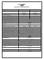
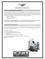
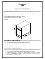
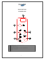
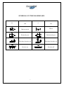
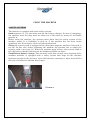
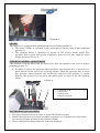
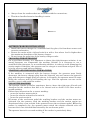
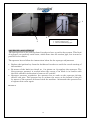
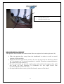
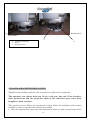
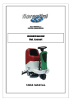
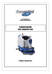
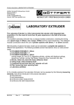
User Manual
SCOIATTOLO 75 - 85
ATTENTION! PLEASE READ THIS MANUAL BEFORE USING THE MACHINE
ING. O. FIORENTINI S.R.L.
INDUSTRIAL CLEANING MACHINES
INDEX
MACHINE DELIVERY
INTRODUCTION
TECHNICAL DESCRIPTION
GENERAL INFORMATION
MANUFACTURER RESPONSIBILITY
INTERVENTION REQUEST
TRANSPORT AND STOCKING
PACKED MACHINE HANDLING
UNPACKING THE MACHINE
UNPACKED MACHINE HANDLING
DESCRIPTION
DASHBOARD
SYMBOLS ON THE DASHBOARD
USING THE MACHINE
Safety Systems
Brake
Batteries Installation
Battery Charger Installation
Choosing the detergent
Starting and Preparing the Machine
Use of the machine
Detergent quantity
Water unload
Squeegee Adjustment
Brushes Replacement
Cleaned area width regulation
SAFETY, MAINTENANCE AND CONTROLS
GENERAL SEFATY RULES
DAILY MAINTENANCE RULES
Maintenance Plan
Batteries
Squeegee Blades Replacement
Suction Motor Maintenance
CONTROLS
Checking the Safety System
Checking the Electric System
Checking the Braking System
SUMMARY
1
page
2
2
3
4
4
4
5
5
5
5
6
6
7
8
8
9
9
10
10
10
10
11
11
12
13
14
15
15
16
16
17
18
19
20
20
20
20
21
MACHINE DELIVERY
AS SOON AS THE MACHINE IS DELIVERED, PLEASE CHECK THAT THERE
IS NOT ANY DAMAGE DUE TO TRANSPORT.
IN
CASE
OF
DAMAGE
OR
MISSING
PARTS,
PLEASE
ADVISE
IMMEDIATELY THE MANUFACTURER.
INTRODUCTION
THIS KIND OF SCRUBBER MACHINE CAN PERFECTLY WASH EVERY
KIND OF FLOOR FROM EVERY KIND OF DIRT WITH AN EXCELLENT RESULT.
THIS IS WHY THE MACHINE MUST ALWAYS BE USED IN A CORRECT
WAY AND MAINTAIN IT. PLEASE, READ CAREFULLY THIS USER AND
MAINTAINANCE MANUAL.
THE
MACHINE
MUST
ONLY
BE
USED
FOR
THE
INDUSTRIAL
CLEANING.
Pease, keep this manual for any future reference
2
TECHNICAL DESCRIPTION
DIMENSIONS
LENGHT
WIDTH
SCOIATTOLO 75
SCOIATTOLO 85
1360 mm
1360 mm
860 mm (with brushes
860 mm (with brushes
protection)
protection)
1360 mm
1360 mm
2
2
Ø 380 mm
Ø 410 mm
750 mm
850 mm
950 mm
1050 mm
160 lt.
155 lt.
250 mm.
310 mm.
electric
HEIGHT
WASHING BRUSHES
WASHING BRUSHES DIMENSIONS
CLEANED AREA WIDTH
SQUEEGEE WIDTH
POLYETHYLENE SOLUTION TANK
POLYETHYLENE RECOVERY TANK
FRONT WHEEL DIAMETER
REAR WHEEL DIAMETER
TRACTION
WEIGHT WITHOUT OPERATOR ON
430 kg.
BOARD
WEIGHT WITHOUT BATTERIES
250 kg.
250 kg.
BATTERIES ROOM (LxWxH)
590x530x325 mm.
ELECTRIC CHARACTERISTICS
ENERGY SOURCE
Nr. 6 batteries (6V)
VOLTAGE
36 V
WASHING BRUSHES ENGINE
1000W 32A 2200rpm
TRACTION DRIVING WHEEL
600w 21A 130rpm
SUCTION ENGINE
850w 23A 16000rpm
FUNCTIONS
DRIVE
Operator on board
Operator on board
U-TURN LANE
2500 mm
SQUEEGEE UP
electrical
SQUEEGEE DOWN
mechanical by pedal
SERVICE BRAKE
mechanical by pedal
PARKING BRAKE
mechanical by pedal
PERFORMANCES
FORWARD SPEED
0 ÷6 Km/h
BACKWARD SPEED
0 ÷4 Km/h
MAXIMUM OVERCOMING SLOPE
10 %
MAXIMUM OVERCOMING SLOPE FOR
5% A 1 Km/h
A U-TURN
CLEANED AREA (m² /h)
4300 m² /h
4700 m² /h
ECOLOGICAL CHARACTERISTICS
NOISE AT OPERATOR S EAR
< 70 dB(A)
NOISE AT OPERATOR S SEAT
< 2.5 m/s²
3
GENERAL INFORMATION
MANUFACTURER RESPONSIBILITY
The manufacturer NOVA is not responsible for any damage due to the noacquaintance or no-fulfilment of the instructions of this manual. The same applies to
changes, modifications, and/or the installation of accessories not authorized by NOVA.
In particular, NOVA is not responsible for any damage caused by:
- Natural calamity
- Erroneous manoeuvres
- No maintenance
Furthermore, the manufacturer is not responsible for any intervention not
performed by NOVA technicians except for ordinary maintenance.
INTERVENTION REQUEST
Intervention should be made after a careful analysis of the damage and its causes. In
any case, when a damage occurs, it is necessary to give the following information to
the authorized Service Centre:
•
•
•
•
•
•
•
Machine model;
Serial number (picture nr. 1);
A detailed description of the damage;
Check done;
Performed adjustments and their results;
Any other information considered useful for this purpose;
Customer address.
Fig. 1
MADE IN
ITALY
Mod. SCOIATT-80M
V 36
Kg 480
CE
S.N.SCO-04-005 2004
Hz.
A 704 W 2650
TRANSPORT AND STOCKING
PACKED MACHINE HANDLING
The machine is delivered in a special package, which is shown in picture nr. 2.
The gravity centre is indicated on the package with a black arrow. The pallet must be
forked in the middle of the side with the black arrow in order to avoid overturning.
The case should be handled with extreme caution.
It is forbidden to lay cases on each other.
Picture 2
UNPACKING THE MACHINE
1.
2.
3.
4.
5.
Cut the plastic bands. Pay attention to the spring back.
Remove the clips that fix the carton to the pallet.
If the case is made of plywood, remove the clips from the each side and the base.
Remove the plastic bands that hold the machine.
Place the machine on the floor.
UNPACKED MACHINE HANDLING
1. Check the machine and install the batteries if they are not installed.
2. If the machine has to be handled for a short transport, disconnect the battery
cables. It is recommended to pack the machine again in its original case if it has
to be handled for a longer transport.
5
DESCRIPTION
DASHBOARD
1
2
3
4
5
6
BATTERY CHARGER INDICATOR
KEY SWITCH
BRUSHES SWITCH
FORWARD/BACKWARD GEAR SELECTOR
SUCTION SWITCH
HORN
6
SYMBOLS ON THE DASHBOARD
0
1
Off
On
Horn
Main switch
Forward gear
Backward gear
Washing brushes off
Washing brushes on
Suction on
Suction off
7
USING THE MACHINE
SAFETY SYSTEMS
The machine is equipped with some safety systems.
Outlet (picture 3), it is the same used for the battery charger. In casa of emergency,
the operator must the plug must be taken out of the outlet by means of its handle
(picture 4).
Before using the machine, the operator must know how the safety system of the
machine works. It is forbidden to plug in, if the problem has not been sorted
completely out. If necessary, ask for a trained technician.
Float: the recovery tank is equipped with a float that stops the machine if the tank is
too full. In this case, before restarting the machine the operator has to empty the
recovery tank o (see page 11). When the machine stops because the recovery tank is
full, the battery charger indicator on the dashboard blinks six times.
Unsufficient battery charge: The electronic card, that controls every function of the
scrubber machine, is equipped with a safety system that stops all the machine
functions (except for the traction) when the batteries autonomy is lower than 20%.In
this way, the batteries lifetime lasts longer.
Picture 3
8
Picture 4
BRAKE
The machine is equipped with parking and service brake (picture 5).
• The service brake is operated by the pedal placed on the right of the footboard
(picture 1).
• The parking brake is operated by means of the service brake pedal. The
operator has to push this pedal completely down and do the opposite when
he/she wants to release it.
STEERING WHEEL ADJUSTMENT
The machine steering wheel can be adjusted so that the operator can reach a proper
position (picture 5).
• In order to adjust the steering wheel position, the operator has to unscrew the
knob placed on the left of the steering column. Then the operator has to move
the steering wheel forward and backward until the best position is found.
Finally, the operator has to screw the knob again in order to fix the steering
wheel.
Picture 5
4
3
2
1
1.
2.
3.
4.
Accelerator pedal
Brake pedal
Brushes pedal
Brushes plate pedal
BATTERIES INSTALLATION
• Pull the solution tank up in order to reach the batteries room;
• Install the batteries in its room as shown in picture nr. 6 making sure that there
are not any breaks or holes in the batteries boxes;
• Never add distilled water after the batteries recharge;
9
•
•
Always clean the surfaces that are in contact with the connections;
Thanks to handles batteries handling is easier.
Picture 6
BATTERY CHARGER INSTALLATION
• Install the battery charger in a ventilated and dry place, far from heat sources and
corrosive substances;
• Protect the mains with a delayed switch or with a fuse whose load is higher than
the maximum absorbtion of the battery charger .
• Do not invert the polarities of the battery charger outlet.
CHOOSING THE DETERGENT
For a good floor cleaning, it is important to choose the right detergent solution. A too
strong detergent can compromise the machine lifetime. It is necessary to use a
controlled foam detergent, or an antifoaming additive, in order to avoid damaging the
suction engine. Otherwise, the operator can use vinegar to avoid foam and pour 50cc of
it in the recovery tank before scrubbing.
STARTING AND PREPARING THE MACHINE
If the machine is connected with the battery charger, the operator must firstly
disconnect the battery charger plug from the batteries one and connect the batteries
plug with the power supply plug (see picture 4). Secondly, the operator must fill water
lifting the recovery tank up and turning the cap. Now the operator can seat on the
machine, start it and wash the surface.
USE OF THE MACHINE
The operator, thanks to his/her experience, has to choose the right type of brush and
detergent for the surfaces that has to be cleaned and to decide if the floor needs a
second washing.
Follow these instructions for a correct washing:
1. press the brushes motor switch;
2. press the solution solenoid valve switch;
3. press the suction switch.
By means of the accelerator pedal the washing brushes and the suction motor are
activated. On the contrary, both the washing brushes and the suction engine are
disactivated after a few seconds if the operator leaves the accelerator pedal. Before the
surface is completely dry, the operator must switch the solution solenoid valve off
because this is not activated/disactivated by the accelerator pedal.
The operator has to do a second washing if the surface is particularly dirty:
10
1.
2.
3.
4.
5.
wash the surface with the squeegee up and the brushes down;
activate the brushes;
press the solution solenoid valve switch;
leave the solution on the surface to dissolve the dirt;
do a second washing with brushes and squeegee down, the suction activated and the
solution solenoid valve opened.
DETERGENT QUANTITY
During the cleaning the operator can control the detergent quantity by means of a
cock, which is on the left of the machine frame.
Important: before checking the water quantity that flows to the brushes, make sure
that the ignition key is not in the dashboard in order to avoid a casual starting of the
machine.
Picture 7
1. water lever
1
WATER UNLOAD
The scrubber machine is equipped with two pipes for water discharge (pictures 8-a and
8-b):
If you need to discharge water from the tanks, you have to place the machine on a
dump well, release the pipe of the tank and open the rubber cap at the end of the pipe
itself.
Picture 8-a
Picture 8-b
11
1
2
1. recovery tank discharge pipe
2. suction squeegee pipe
3. solution tank discharge pipe
3
SQUEEGEE ADJUSTMENT
The squeegee has to be well regulated in order to have a perfect dry system. This kind
of squeegee can perfectly suck water, which flows into the suction pipe, but it must be
parallel to the surface.
The operator has to follow the instructions below for the squeegee adjustment:
•
•
•
Replace the ignition key from the dashboard in order to avoid the casual starting of
the machine.
By means of the knob (see detail nr. 1 in picture nr. 9) regulate the squeegee. The
best squeegee pressure is reached when the corner of its blade is in contact with
the floor and their inclination is between 45° and 60°.
Squeegee pressure regulation: the operator has to work on the squeegee driving
wheels cam pins. The operator has to unloose the screw at the bottom of the pin
by means of the spanner delivered with the machine. Afetrwards the operator has
to tighten this screw again.
Picture 9
12
1
1.
2.
3.
3
squeegee height screw
squeegee fastening screw
squeegee inclination screw
2
BRUSHES REPLACEMENT
The operator has to follow the instructions below to replace the brushes (picture 10):
Ø Take the ignition key away from the dashboard in order to avoid a casual
starting of the machine;
Ø Right side brush replacement: remove the case by means of the knob (see detail
nr. 1 in picture nr. 10-a) and translate it outside. Translate counterclockwise
the right brush and remove it;
Ø To set a new brush up: put the coupler pins under the brush support slots, pull
the brush up and translate it (clockwise for the right brush and
counterclockwise for the left one);
Ø Set again the brushes cases up and fix them by means of the knob.
13
1
Picture 10-b
Picture10-a
2
1.
2.
3.
Protection brush knob
Brush
Brush protection
3
CLEANED AREA WIDTH REGULATION
Thanks to this srubber machine, the cleaned area width can be regulated.
The operator can choose between 70 cm. or 80 cm., but only if the brushes,
their protections and the propeller shaft of the reduction gear have been
bought for both versions.
The operator has to follow the instructions listed below for machines with central
brushes in order to regulate the cleaned area width.
• Take the ignition key away from the dasboard in order to avoid a casual start of the
14
•
•
•
•
•
•
•
machine;
Remove the brushes and the protection cases as shown in paragraph BRUSHES
REPLACEMENT ;
Remove the brushes plate and at the same time the hydraulic pipes and the electric
cables;
Choose between the two brushes plate version and set up the right propeller shaft
of the rectucions gears;
Set the brushes plate up again, the hydraulic pipes and the elctric cables;
Set the chosen brushes version up: Ø 380 brush for SCOIATTOLO 70 or Ø 410
brush for SCOIATTOLO 80;
Set the brushes protection cases up. They are the same for both versions.
Set the right squeegee up for the brush chosen version.
SAFETY, MAINTENANCE AND CONTROLS
GENERAL SAFETY RULES
The rules listed below must be carefully followed in order to avoid damages to the
operator and/or the machine.
•
Read carefully the labels sticked on the machine and do not cover them for any
reason;
15
•
•
•
•
•
•
•
•
•
•
•
•
•
•
•
•
•
•
•
•
Do not mix detergents of different kind in order to avoid the development of
dangerous gases;
Do not use the machine in places with explosive substances;
Do not use the machine as a means of transport
Do not use acids which could damage the machine;
Do not intake flammable liquids for any reason
In case of fire, please use a powder extinguisher. Do not use water.
If the machine does not work in the correct way, please make sure that the defect is
not caused by a lack of ordinary maintenance. On the contrary, please immediately
contact NOVA Service;
Before starting the machine again, please make sure that all fixed or removable
protections are in their position;
Do not wash the machine with corrosive substances or with water jets;
Do not keep the machine in an environment with a temperature < 3° C;
Avoid to leave the machine in a no-authorized place for the scrapping. In fact, the
machine is made of materials that must be recycled and disposed in authorized
centres;
The machine does not develop dangerous vibrations;
Keep always the machine far from kerbstones and drive slowly on surfaces with
holes;
Make sure that there are no people near the machine during the cleaning;
Do not start the machine if it is under maintenance;
Do not drive too fast while turning, in particular on sloping surfaces;
It is absolutely forbidden to touch the inferior side of the machine during
the cleaning. If it is necessary, please keep the ignition key away from the
dashboard;
The operator must carefully read this manual and do not use alcohol or medicines
before driving the machine;
The machine cannot be used in places with dangerous substances and in
particular with explosive atmospheres or with a bad microclimate;
Please, disconnect the battery when the machine is not working.
Important: the operator has to have a sufficient knowledge of the Italian
language.
Daily maintenance rules
While the operator is cleaning, maintaining the machine or replacing some of its parts,
the ignition key must not be in dashboard.
MAINTENANCE PLAN
EVERY DAY
• Clean the recovery tank and the suction engine filter
EVERY WEEK
16
• Check if the squeegee pipes and the suction ones are clean
• Check the squeegee rubber blades state
• Check the water level of the batteries
EVERY MONTH
• Check the filter of the solution tank
EVERY SIX MONTHS
• Check the connection of the batterie cables
EVERY YEAR
• Check the coal brushes of each engine
EVERY TWO YEARS
• Check the safety devices
• Check the electric system
BATTERIES
•
•
•
•
•
•
Keep the battery room open during the batteries recharge;
It is forbidden to use flames and/or to smoke near the batteries;
Pay attention to the battery acid;
Do not develop sparks near the batteries;
Pay attention to the batteries gazes, which can burst;
Do not invert battery polarities.
CHECKING THE BATTERY CHARGE
The operator has to check the batteries charge when the machine is on duty by means
of the indicator on the dashboard, which shows:
•
•
•
Green light: charged battery
Yellow light: slightly charged battery
Red light: uncharged battery
HYDROMETRY
In order to check the batteries hydrometry the operator has to follow the instructions
below:
1. By means of a hydrometre draw a small quantity of electrolyte so that the floater
reaches the surface;
2. Make sure that the floater inside the hydrometre is not blocked;
3. For a new measurement, after having filled the batteries with distilled water, the
operator has to wait until the liquid inside each battery becomes homogeneous.
WATER FILLING UP
1. Fill distilled water up in each battery cell before the recharge. The liquid inside the
batteries has to be of 6 mm. over the plates;
2. The operator has to repeat the same operation every time the level decreases (every
week).
CHARGE LIMITS
It is not necessary to recharge the batteries if the hydrometry, after a work day, is not
under 1,24 (28 Bè). The highest suggested temperature is 45°C. If the electrolyte
17
temperature increases more than 10/12 °C compared to the outside temperature, the
batteries can be overcharged.
OFF DUTY OR INACTIVE BATTERIES
Inactive batteries looses their automatically their charge. If batteries do not
continually work, the operator has to:
Ø Charge the batteries once a month with a final stream intensity until gas is
spread and the batteries voltage and weight are constant for 3-4 hours. This
operation has to be done even if the absolute weight is high;
Ø Keep the batteries in a dry room.
BATTERIES TECHNICAL FEATURES
TENSION
CAPACITAY
PWEIGHT
DIMENSIONS (LxLxH)
V6
240 A/h
28 Kg
240 x 180 h 280
BATTERY CHARGER TECHNICAL FEATURES
IN
OUT
V 230, Hz 50, A5
V 36, A 30
This battery charger can also charge batteries of a different brand.
BATTERIES DISPOSAL
Old batteries are toxic wastes and they have to be thrown in a suitable and authorized
place for the batteries disposal. For a short storage, old batteries must be located in an
authorized room. Moreover, they must be stored in sealed plastic tanks, whose
capacity is not lower than the electrolyte.
SQUEEGEE BLADES REPLACEMENT
Squeegee blades must be replaced when their hedge is worn. A perfect hedge in the
blade allows a perfect dry (picture 13).
Follow these instructions to replace the squeegee blades:
1. Remove the squeegee from the machine and lay it on a table;
18
2. Remove the internal and external knobs, the steel strips and the worn blades;
3. Set the new blades up, tighten the knobs and regulate the squeegee.
Picture 13
8
7
6
10
5
1
4
3
9
1.
2.
3.
4.
5.
6.
7.
8.
9.
10.
Squeegee
Washer
Throttle
Rear rubber blade
Front steel
Washer
Throttle
Side bumper
Rear steel
Front rubber blade
2
SUCTION ENGINE MAINTENANCE
The suction motor has to be checked up and cleaned. Every six months motor brushes have to be
checked and replaced if it is necessary.
In order to maintain the suction motor please follow the instructions below:
19
1. Take the ignition key off the dashboard, disconnect the plug, remove the steel plate
that fixes the suction motor and the motor itself (picture 14);
2. Remove the sponge filter under the motor, wash it and put it again in its position;
3. Check the motor fan through the hole in the front side of the suction motor;
4. Remove the plastic cover, lossen the screws and both the brushes supports and
check the motor brushes (see detail 2 in picture 5.1);
5. Do now the opposite operations to set everything up again.
Picture 14
1.
2.
3.
3
plug for cables connection
coal brushes engine
engine fastening plates
1
2
Trained personnel only can service the machine and especially
electric and electromechanical parts by means of suitable tools
and equipments. Make reference to NOVA only for service and
spare parts.
CONTROLS
A trained technician has to check if themachine is safe and if it shows any particular
damage or defect before the first starting or after changes and repair.
20
CHECKING THE SAFETY SYSTEM
Every year a trained technician has to check the safety deviced of the machine. In
particular, the machine has to be completely overhauled every 5 years by a NOVA
technician.
CHECKING THE ELECTRIC SYSTEM
It is very important to check the electric system up every two years. Disconnected
cables or burnt cables must be immediately replaced.
Interventions on the electric system must be carried out by a trained technician.
Every kind of intervention not explained in the operator manual must be carried out
by NOVA s technicians.
CHECKING THE BRAKING SYSTEM
The braking system has to be checked every 3 months.
DIAGNOSTIC
The electronic card is equipped with a particular system which shows the machine
errors through quick flashings on the battery charger display placed on the dashboard.
The number of switched on LEDs represents one of the errors listed below:
n.° flash
Description
Solution
1
The gear command is already active on ignition: the ignition key has been
activated when the gear command was already plugged in.
2
Battery too unloaded or subject to tension caused by a short circuit on the
power. Indicates that the tension of the system is lower than the minimum
level required for a proper functioning.
3
Maximum tension on the battery. Indicates that the tension is too high and
could break the regulator.
4
Motor not connected or wrong contact on the motor circuit. This may
happen when the motor brushes do not correctly lie on the rotor or when
cables are loosened.
5
Internal fault of the regulator or earth on the motor.
It is required to release the gear command in order to
eliminate the flashing signals. Should this not happen,
it may be necessary to reset the acceleration system.
Verify that the battery is not too unloaded and if
necessary reload the battery. Alternatively verify
whether any electrical connections are loosened. If this
doesn’t solve the problem, it may be necessary to
replace the system.
Verify the connections, the functionalities and the
integrity of the motor.
There could be a negative dispersion on the motor
circuit; alternatively, verify the regulator.
6
7
8
9
10
Temperature of the power circuit is too high; this happens when the
temperature of the mosfet is higher than 75°C +/- 5°C, i.e. when the
machine has worked in overload conditions, e.g. on too steep slopes for too
long, or in working temperature higher than 40°C. This may also happen in
case of damage of the winding of the motor, which may lead to unusual
absorption of current.
Motor is already working on start. Indicates that the machine is being starter
when it is (or its motor) is already working.
Software fault of the microcontroller or hardware problem. This may
happen in case of faults to the circuits, which measure the current and the
loads.
Battery empty, indicates that there occurred a blocking of the brushes.
21
Wait until the temperature has cooled down.
Stop the machine and thereafter do it again
Try to stop and then restart the machine. If the fault
appears again it is required to verify the regulator.
Recharge the battery
SUMMARY
HOW OFTEN
TECHNICIAN
Safety devices
Every 2 years
Trained technician
Electric system
Every 2 years
NOVA technician
Braking system
Every 3 months
Trained technician
Complete check up
Every 5 years
NOVA technician
Recovery tank cleaning
Every day
Operator
Clean water tank
Every month
Operator
Suction motor filter
Every day
Operator
Suction pipes cleaning
Every week
Operator
Squeegee cleaning
Every week
Operator
Squeegee blades
Every week
Operator
Battery water level
Every week
Operator
Battery cables fixing
Every 6 months
Trained technician
INSPECTION
MAINTENANCE
22
Mat. n.
S.N.
Nr. de serie
_____________________
Data di spedizione
Shipment Date
Date de spedition
_____________________
Distributed by:
ING. O. FIORENTINI s.r.l.
“THE BEST IN FLOOR MACHINES”
FILIALI:
20132 MILANO – Fax. 02/2592779
Via Palmanova 211/a – Tel. 02/27207783 - 2564810
00155 ROMA – Fax. 06/22754075
Via Carlo Carrà 13 – Tel. 06/22754040-2275060
STABILIMENTO:
50030 PIANCALDOLI (FI) – Fax. 055/817144
Loc. Rombola – Tel. 055/8173610
23