1
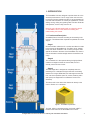
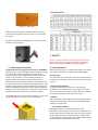
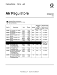
1353.06
53.27
1
2
3
4
431.80
17.00
5
ber
16,
cai-e
ngin
eerin
gD
02
ece
m
3
Dec
emb
er 16
,
4
Carlo
sT
2010
5 PM
5:24
:4
2010
:45 PM
5:24
REV.
SHEE
SIZE T
SHEE
T: 1
A
SCAL
E
OF 1
1:24
QTY
pe
BUILD r
1
REVI
SED
BY
A
7
2
685.80
27.00
.35
1165 8
45.8
1
6
PRE
621.22
24.46
D
DRAW
N BY
5
N/A
----
----
Assem4
N/A
DRAWN BY
N/A
6
7
B
WEIGHT
-- Gage
431.
80
17.0
0
CAD FILE:
PART SIZE
----
Carlos T
December 16, 2010 5:24:45 PM
4
5
QTY
BU
685.
80
27.0
0
MATERIAL
STATION 4
Install
----
STATION 3
ANGLES STATION 2
.X 1
DESC
RIPTIO
N
STATION 1
TOLERANCES ARE:
DECIMALS
.XX .03
.XXX .015
ED DRAWING, FRACTIONS
ALLY UPDATE.
1/32
E DRAWING.
----
REVISED BY
SHEET
SIZE
REV.
2
USER MANUAL
C
A
PRE
cai-engineering02
December 16, 2010 5:24:45 PM
3
Asse
m4
DESCRIPTION
----
DIMENSIONS ARE IN:
INCHES AND FEET
CAD
FILE:
ITEM NO.
UNLESS OTHERWISE SPECIFIED:
ALL BENDS ARE 90
WEIG
HT
CONTAINED IN THIS
OLE PROPERTY OF
A, INC. AND MUST
N REQUEST. ANY
THIS DOCUMENT,
RT, WITHOUT THE
N OF CLEAN AIR
RICTLY PROHIBITED.
.62
1535 6
60.4
SCALE
SHEET:
1
CLEAN AIR
C
7
533.40
D
21.00
762
30.00
4
5
2
3
56
436.
9
17.1
1
D
D
1
718.06
28.27
533.40
21.00
C
1
SCANDMIST UNITS
6
762
30.00
B
2
3
D
8
D
4
5
2
6
7
1353
.0
53.2 6
7
.40
1041 0
41.0 8
C
3
1165
.3
45.8 5
8
718.06
28.27
4
B
B
80
685.
0
27.0
6
C
42
824.
6
32.4
5
C
ece
02
gD
rin
Y
ED B
inee
REVIS i-eng
A
494.22
7 Superior
19.46
T
SHEE
SIZE
REV.
THE INFORMATION CONTAINED IN THIS
DOCUMENT IS THE SOLE PROPERTY OF
431.80 DESCRIP
---BY
WN
February, 17.00
2011 Clean Air ScandmistDRAUser
os TManual
TION
B
A
ca
0:45
0 4:3
, 201
er 17
b
m
e B
Dec
A
SCA
PRE
per
QTY ILD
BU
All Rights Reserved ©Clean Air America 1
685.80
Carl
FILE:
1
CAD
ssem
PM
3
Drive Rome, GA 30161 TOLL 27.00
FREE: (866) 665-1829 Phone:
706-291-1700 Email: [email protected]
HT
RIAL
WEIG
ge
MATE
1:48
4
N/A 431.80
O.
-- Ga
-- www.clean-air.com
N3
EM N
LE
1
EET:
SH494.22
UNLESS OTHERWISE SPECIFIED:
ALL BENDS ARE 90
ITEM NO.
OF 1
IT
:
IFIED
PEC
1
ISE S90
ON
ERW
STATI
OTH DS ARE
S
S
:
N
IN
DESCRIPTION
UNLE ALL BE
ARE
--
ll
Insta
O
STATI
----
4
ON
STATI
---
A
T
PAR
SIZE
N/A
685.80
A
17.00
5
QTY per
BUILD
2
Table of Contents
1. INTRODUCTION ............................................................................................... 1
1.1 FUNCTION AND DESCRIPTION . .................................................................. 1
1.1.2 RECEIVING AND INSPECTION ................................................................. 2
1.2 TECHNICAL DATA ......................................................................................... 2
2. SAFETY ............................................................................................................ 2
2.1 SAFETY EQUIPMENT..................................................................................... 3
2.2 MOUNTING ..................................................................................................... 3
2.3 ELECTRICAL INSTALLATION ....................................................................... 3
2.4 NOISE ............................................................................................................. 3
2.4.1 ROTATION OF THE BLOWER .................................................................... 3
2.5 DRAINAGE OF COLLECTED FLUID.............................................................. 3
3. INSTALLATION / MOUNTING .......................................................................... 3
3.1 DESCRIPTIONS ............................................................................................ 3
3.2 ELECTRICAL INSTALLATION ....................................................................... 3
4. OPERATION AND MAINTENANCE ................................................................. 3
4.1 FILTER 1 - PRE-FILTER ................................................................................. 4
4.2 FILTER 2 - FINE FILTER ................................................................................ 4
4.3 MICRO FILTER ............................................................................................... 4
4.4 CLEANING THE FILTER (SCANDMIST 200D, 400D AND 600D) ................. 4
5. SPARE PARTS ................................................................................................. 4
6. DUCTING........................................................................................................... 4
ii
All Rights Reserved ©Clean Air America - February, 2011 Scandmist User Manual
1. INTRODUCTION
The ScandMist Units are designed to provide clean air to the
workshop environment. The “R” range of the units are used
to remove oil smoke particles and the “D” range separates oil
mist and water emulsions in a variety of applications, such as
drilling, turning, milling and grinding. Both units also eliminate
solid particles, such as chips, from the air.
Note: No one is allowed working with or performing service
on ScandMist R and D units without first reading and
understanding this manual.
1.1. Function and Description
ScandMist R and D are built according to the drawing in the
brochure. The different filters separate the polluted air in three
stages:
Stage 1
Stage 2
Stage 3
Oil removal filters collect the oil or coolant and allow it to drain
to the base of the ScandMist unit. The filters do not “absorb”
the oil, but rather coalesce it until it is heavy enough to drain
against the airflow to the base of the ScandMist unit, where it
can be collected or drained straight back to the machine tool
sump.
The “scrubbed” air is then passed through a highly efficient
coalescer at stage two. After the second filter, the air is
virtually 100% free from oil mist.
The third stage filter is designed to completely clean the
remaining air to a standard far higher than the surrounding
ambient air. Using a HEPA filter, this final stage ensures that
fine, sub-micron particles (trace oil, smoke, bacteria, pollen
and spores) are trapped and not allowed to return to the
workshop.
The silent, built-in fan returns the cleaned air directly to the
room or further on in a ductwork.
Figure 1. ScandMist Top Module
The fluid, which is separated, drains out through a NPT 1”
thread on the bottom of the ScandMist unit for reuse.
All Rights Reserved ©Clean Air America - February, 2011 Scandmist User Manual
1
1.2 Technical Data
Figure 2. 1” NPT Drain
A differential pressure gauge, indicating the pressure drop
over the respectively filter stages at-a-glance, is mounted at
the factory.
The filters are fastened in parallelograms with the help of the
included tools, see figure 3.
2. SAFETY
Figure 3. Filter Clamps
1.1.2 Receiving and Inspection
Congratulations on buying you new Clean Air ScandMist!
After receiving your new ScandMist, remove the main packing
list from the unit and check carefully it matches with the
complete shipping. All ScandMist units are land transported,
usually in dry van trailer. Units are partially packed on a
wooden platform and shipped on its side. Remove the
package and take the unit off the platform. Check the unit and
any other device sent for damages during transportation. If any
damage is found, please call the transportation company and
Clan Air immediately. Accessories may be shipped separately
according to the order. Depending on the size, some parts can
be packed with the ScandMist or in a different package.
The Scandmist unit has four lifting lugs at the top in order to be
moved and placed more easily on its final destination.
Note: For function guarantee and safety Clean Air does not
allow modifications or changes of the machine. Warning!
Never connect the ScandMist to explosive gases.
2.1 Safety Equipment
When performing service or cleaning the machine you should
use protective respiratory equipment and safety goggles.
2.2 Mounting
The machine must be fastened to the floor with bolts when it is
assembled. The machine must be turned off when performing
a service.
2.3 Electrical Installation
An authorised electrician must carry out the electrical
installation of the ScandMist unit. The machine is provided
with a motor switch and a motor protector. Make sure that the
fan rotates according to the direction of the arrow.
2.4 Noise
The sound level of the ScandMist unit varies depending on the
motor/blower configuration. Please check the appropriate spec
sheet for more information.
Figure 4. ScandMist Top Module
2
2.4.1 Blower Rotation
If the blower rotation is not correct, there will be a low
performance and an increase of noise in the unit. Make sure the
blower rotate correctly. To make sure of this you need to take out
the third stage filter and do a visual inspection. There will be an
arrow indicating the correct rotation of the blower. Make sure that
the blower rotates in the direction of the arrow.
All Rights Reserved ©Clean Air America - February, 2011 Scandmist User Manual
2.5 Drainage of collected fluid
The drained and separated oil from the machine should be
collected in a bucket or similar. It is important that leakage to
the floor is minimised in order to lower the risk of skidding.
Also there’s an optional pump return accessory that can be
connected to the machining center in order to recycle the
collected fluid.
of water based detergent solution and rinse it by flushing
hot water from the clean side of the filter. Do not use high
pressure; the filter can then be damaged. Let the filter get
dry before mounting it back into the ScandMist. After a few
washes the filter is expired and must be changed to a new
one. The filter can also be washed in a chamber washer with
water based detergent solution.
3. INSTALLATION/MOUNTING
Note: The water has to be clean.
3.1 Descriptions
5. SPARE PARTS
1. Place the ScandMist unit without blocking the inlet or the
filter doors.
2. Bolt the ScandMist unit to the floor.
3. The drainage at the bottom should be connected to the
pump returning mechanism or to a collecting vessel.
4. To avoid the air returning to the unit through the connection,
the drainage tube is equipped with a drain trap. This should
have at least a 150 mm high column of oil.
5. Filters should be assembled and disassembled according
to figure No. 3 in Section 1.1
3.2 Electrical Installation
An authorised electrician must perform the electrical
installation. The ScandMist is equipped with a motor switch
and a motor protector. If Delta-connection is required the
motor protection must be changed and the connection on the
motor changed according to the wiring diagram below. See
Chapter 1.3 for motor data.
For guaranteed function of Scandmist units, we only
recommend the use of original spare parts. Always contact
Clean Air if you have problems with service or repairs, or when
replacement parts are required. For spare parts and support
on the unit, contact:
Clean Air America Inc.
7 Superior Drive
Rome, GA 30161
TOLL FREE: (866) 665-1829
Phone: 706-291-1700
mail: [email protected]
www.clean-air.com
6. DUCTING
In case that you’re responsible for the installation of ducting for
the unit, there’s a couple of guidelines that you most follow:
4. OPERATION AND MAINTENANCE
•
No one is allowed to work with or perform a service upon a
ScandMist R or D without first reading and understanding this
manual.
•
•
The ducting needs to be rated for at least a pressure of
-10 in w.c.
The ducting most be appropriate for oil mist and liquids.
All horizontal ducts must have a 2º drop in order to avoid
liquid build up inside the ducts.
Always contact Clean Air when you are uncertain of
something.
4.1 Filter 1 – Pre-filter
The pre-filter is to be cleaned or replaced when reaching a
pressure drop of 2.5 in w.c.
4.2 Filter 2 - Fine Filter
The fine-filter is to be replaced when reaching a pressure drop
of 2.5 in w.c.
4.3 Micro Filter
The micro-filter, HEPA (H13), is to be replaced when reaching a
pressure drop of maximum 3.6 in w.c. Not washable.
4.4 Filter Cleaning (200D, 400D, 600D)
Filter 1 in the 200D, 400D and 600D units can be washed in
hot water maximum 60°C. Wash the filter with a gentle mixture
All Rights Reserved ©Clean Air America - February, 2011 Scandmist User Manual
3
4
All Rights Reserved ©Clean Air America - February, 2011 Scandmist User Manual