1
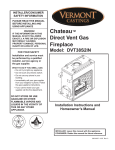
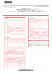
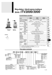
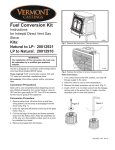
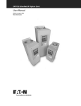
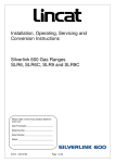
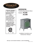
Burner Orifice (3 or 4)
(Refer to Table 1 or 3
to Confirm Sizes)
Fuel Conversion Kit
20011992, 20012367, 20012368
LP to Natural:
20013200, 20013199, 20013196
for Models: DVT38IN,
DVT44IN, DVT38S2IN
WARNING!
The installation of this conversion kit must
only be undertaken by a qualified, certified
gas appliance installer.
Pressure
Test Adapter
Valve Minimum
Rate Screw
(DVT44,DVT38S2)
Label
Installation Instructions
Kits:
Natural to LP:
Pilot Orifice
Valve Minimum
Rate Screw
(LP) (DVT38)
CAR205
Fig. 1 Carton contents.
CAUTION: Logs may be hot.
CAR205
3. Models DVT38, DVT44
DVTIN
a. With a Phillips or Robertson screwdriver, remove
fuel
conversion
the two (2) screws
holding
the fettle to the burner
assemblies. With5/07
a hex,djt
remove the two (2) hex
nuts holding the burner tube to the front of the
burner assembly. Remove burner tube.
b. With the 3/8” socket remove two (2) hex nuts
holding the left burner leg. Remove burner leg.
(Fig. 2)
This kit is designed for conversion of the Direct Vent
Gas Heater Models DVT38, DVT44 and DVT38S2
equipped with the American Flame AF-4000 Series
valve.
Tools required for conversion: TORX T20 Security Tee
bit, 3/8” and 1/2” deep well socket, Phillips or Robertson
screwdriver, 5/32” allen wrench, small flat blade screwdriver, 7/16” nut driver or socket.
Check Contents of Shipping Carton
Compare contents of Figure 1 with actual parts received. If any parts are missing or damaged, contact
your dealer before starting conversion.
Conversion Precautions
Allow unit to cool if it has been operating.
Before proceeding with conversion shut off fireplace
and turn gas supply OFF. Turn OFF any electricity that
may be going to appliance.
Conversion Procedure
1. Remove glass frame. Refer to Homeowner’s Manual.
2. Remove lava rock, volcanic rock, embers and logs.
Carefully remove brick panels.
Hex Nuts
FP1559a
Fig. 2 Use 3/8” socket to remove hex nuts holding left burner
leg.
c. Slide the burner housing assembly to the left and
FP1559a
away. Adjust air shutter
setting. Pull burner tube
remove
nuts air shutter setassembly forward and
out. Adjust
ting. Refer to Table3/05
2.
d. Remove two (2) screws holding the pilot assembly to the burner assembly. Move the pilot
assembly toward the back.
e. Slide the burner housing assembly to the left and
away.
f. With the 1/2” socket, replace the three (3) injectors. Refer to Table 1.
3. Model DVT38S2
a. With a Phillips or Robertson screwdriver, remove
the four (4) nuts holding the fettle to the burner
assemblies. With a hex, remove the two (2) hex
nuts holding each burner tube to the front of the
20012371 11/07 Rev. 3
1
Hex Nuts
FP1476
Fig. 3 Use a 3/8” socket to remove hex nuts holding burner
legs.
b.
c.
d.
e.
burner assembly on both sides. Remove burner
tubes.
Remove two (2) hex nuts holding the left burner
leg. Remove burner leg.FP1476
(Fig. 3)
Remove two (2) screwsbracket
holding screws
the pilot assembly to the burner assembly. Move the pilot assem4/04 djt
bly toward the back.
Slide the burner housing assembly to the left and
away.
Replace the four (4) injectors. Refer to Table 3.
5. Remove pilot orifice with 5/32” Allen wrench. (Fig. 5)
6. Install the conversion orifice.
7. Reinstall pilot hood. Be sure to align hood with index
tab.
Valve Conversion
1. Remove two (2) screws holding the pilot assembly
to the burner assembly. Move the pilot assembly
toward the back wall.
2. Using a back-up wrench, disconnect the gas supply
fitting near the right rear corner of the firebox.
3. Remove four (4) screws holding the burner assembly to the firebox floor.
4. Carefully slide the burner assembly out of the way.
5. Remove 13 screws around the perimeter holding
large access panel on the of the firebox.
6. Carefully pull back the panel just enough to gain
access to control box.
7. Locate the black plastic cap on the gas valve. (Fig.
6) Remove the black cap by pulling the cap straight
off. Note the position of the marker on the top of
the rotary knob. This marker will point to NAT or LP.
(Fig. 7)
Black Plastic Cap
Pilot Hood
Pilot
Bracket
CO133
Fig. 4 Remove pilot hood.
Index Tab
Minimum Rate
Screw
Allen Wrench
CO138
Front of Fireplace
Fig. 6 AF4000 Valve in place.
Snap Ring
CO133
pilot hood
3/07
CO134
Fig. 5 Remove pilot orifice.
Replace Pilot Orifice
CO134
4. Remove pilot hood by lifting
up. (Fig. 4) NOTE: It is
AF pilot orifice
not necessary to remove
the
3/07 pilot tube for conversion.
22
8. To convert the valve from NG to LP, push in the
knob and rotate 90° (1/4 turn). NOTE: The shaft
should point to LP. The shaft will remain pushed-in.
9. Remove the slotted brass minimum rate screw
located in the valve next to the motor drive. (Fig. 7)
10. Replace the minimum rate screw with the one
provided in the LP conversion kit supplied with this
fireplace. Ensure the screw is fully installed.
11. Install the enclosed identification label to the valve
body where it can be easily seen.
12. Reinstall steel panel.
�����
��������
����
Pilot Adjustment Screw
���
���
��
��
Gas Type
Marker
CO137
Minimum Rate
Screw
Fig. 7 Remove black plastic cap and adjust rotary knob to
correct gas type. (LP position shown) Replace minimum rate
screw with one supplied in conversion kit.
13. Reinstall burner to original position. Reinstall burner
leg, burner tube and fettle. Re-attach supply tube to
gas supply fitting. Using a back-up wrench, tighten
securely.
14. Test for leaks. Apply electric and gas to the system.
15. Light the pilot burner using the remote control. With
soapy solution check for leaks around the pilot assembly where the tube enters the pilot assembly.
Tighten fitting if necessary.
16. Light the main burner and check for leaks around
the burner supply tube fittings and burner orifices.
Tighten if necessary.
17. Turn fireplace OFF.
18. After the conversion and leak checks have been
made, manifold outlet pressure can be checked
with a manometer at the test ports located at the
side front edge of the fireplace opening. The lower
test port is manifold outlet pressure.
CAUTION: Turn off the gas supply before
removing test port plug.
�����
�����������������������
����
19. Using a 7/16” nut driver, remove the threaded plug
from the test port.
20. Thread the supplied extension adaptor into the
open test port.
21. Attach a 1/4” diameter pressure gauge flexible hose
fully onto the barb of the adaptor.
22. Turn on gas supply and operate valve with remote
control as needed to indicate gas pressure. The
manifold pressure for LP should be approximately
10.0” wcp.
CAUTION: Turn off the valve and gas supply
before removing test port adaptor and replacing plug.
23. After test, remove adaptor and replace plug.
24. Turn on gas supply and check that plugs are tight
and leak free.
25. Follow instructions in Homeowner’s Manual to
re-assemble brick panels, logs, lava rock, volcanic
rock, embers and andirons.
26. Replace glass frame.
27. Conversion complete.
Pilot Flame Adjustment
Typically, the top 3/8” or 1/2” of the thermopile should
be engulfed in the pilot flame. (Fig. 8)
To adjust pilot burner: Adjust pilot screw on valve to
provide properly sized flame..
FP1229a
Fig. 8 Correct pilot flame appearance.
3
Table 1 Injector Orifice Size Matrix
Kit #
20011992
Model
DVT38IP
20012367
DVT44IP
Kit #
20013200
Model
DVT38IN
20013199
DVT44IN
Front
#66
(.033”)
#63
(.037”)
Front
#54
(.059”)
#53
(.059”)
Conversion to LP
Burner Orifice
Part #
Middle
Part #
Rear
20009182
#59
20000664
#50
(.041”)
(.070”)
20006251
#57
20004587
#49
(.043”)
(.073”)
Conversion to Natural Gas
Burner Orifice
Part #
Middle
Part #
Rear
20000130
#54
20000130
#30
(.055”)
(.128”)
20007347
#40
20004263
#23
(.098”)
(.154”)
Input (BTU/hr)
Part #
Minimum Maximum
30000337
36,000
46,000
20006252
45,000
60,000
Input (BTU/hr)
Part #
Minimum Maximum
20009175
32,000
46,000
20009044
37,000
60,000
Table 2 Air Shutter Settings
Conversion to LP or Natural Gas
Burner Tube
Burner Housing
Model
Air Shutter Setting Air Shutter Setting
DVT38IP
Fully open
n/a
DVT44IP
Fully open
Fully open
Table 3 DVT38S2 Injector Orifice Size Matrix
Conversion to LP
KiT #
20012368
Model
DVT38S2IP
Burner
Burner
Housing/
Housing
Part #
Pilot
#55
30000333
#54
(.052”)
(.055”)
KiT #
20013196
Model
DVT38S2IN
Burner
Burner
Housing/
Housing
Part #
Pilot
#38
20009310
#38
(.101”)
(.101”)
Part #
20000130
Burner
Tube
#57
(.043”)
Part #
20004587
Burner
Tube
#57
(.043”)
Part #
20004587
Input (BTU/hr)
Min.
Max.
45,000
56,000
Burner
Tube
#45
(.082”)
Part #
20010169
Input (BTU/hr)
Min.
Max.
38,000
56,000
Conversion to Natural Gas
Part #
20009310
Burner
Tube
#45
(.082”)
Part #
20010169
Table 4 Valve Minimum Rate Screw
Model
DVT38IP
DVT44IP
DVT38S2IP
DVT38IN
DVT44IN
DVT38S2IN
Drill Size
#31 (.120”)
No Shank
Screw
Part #
20012364
20012264
ID Stamp
31
00
No Shank
Screw
20013198
0
CFM Corporation
2695 Meadowvale Blvd. • Mississauga, Ontario, Canada L5N 8A3
800-668-5323 • www.cfmcorp.com
© CFM Corporation
44