1
page 16
3.6.
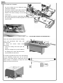
CONNECTION TO SUCTION SYSTEM
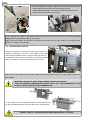
Ø90mm
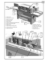
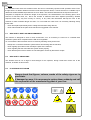
A proper suction reduces at the minimum the risks for the operator of
dust and smoke (due to glue heating) inhalation, besides aids better
and more efficient functioning of the machine.
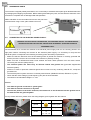
Make sure that the suction system to which the machine has to be
connected can guarantee a flow rate of at least 900 cu.m/h at a
speed of about 20 m/s.
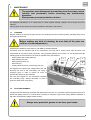
Connect the suction system to the machine with a flexible tube of a
90 mm I.D. on the left side of the machine; tighten the tube with
clamps. Position the tube in such a way to not obstacle any
movements of the operator during normal working operations.
The machine is delivered without exhaust system. The user has to install a
proper exhaust fan depending on the type of use, the material and the timing
of use of the machine. This system has to keep the dust concentration below
the value allowed by the law of the country where the machine is installed.
ALWAYS WORK WITH THE MACHINE CONNECTED TO THE SUCTION SYSTEM AND WITH
THE SUCTION SYSTEM ON
4.
SET-UP
4.1.
PNEUMATIC PRESSURE SET-UP
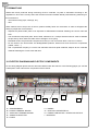
R2
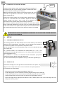
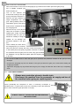
The working pressure has been already set on correct values by the technical
R1
personnel of the manufacturer. If necessary, you can operate on the handle of
the pressure regulator to turn up/down the air pressure value.
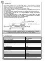
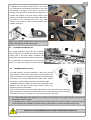
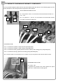
On the machine there are two air regulator groups, one on the left (R1) and one
on the right (R2):
R1 = pressure ±6 bar; it is connected to the electrovalves YV1 – YV2 – YV3
controlling the inserting edge cylinder (YV1), the cutting cylinder (YV2) and the
end-cutting blades (YV3)
R2 = pressure 3 - 3,5 bar; it is connected to the electrovalve (YV4) which
T
controls the pursuing phase of the end-cutter group.
To unload condensation press upward the cap (T) of the left air regulator (R1)
4.2.
EDGE SET-UP
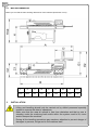
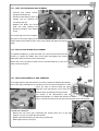
Check that the edge is of the right size for the thickness of the panel. The
edge must not overlap more than 2 mm on each size of the panel (respect to
the thickness of the panel itself)
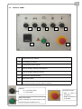
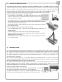
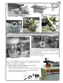
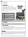
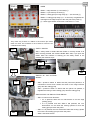
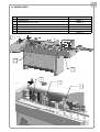
− Place the reel on the reel support as depicted in figure (A)
− Lift the edge-guide up to the maximum necessary height working on the handle (B)
− Lift the set-up washer (C) up to the maximum necessary height and lock it in position
− Insert the edge land et it move on until it is close to the edge feeding roller (D)
− Set-up the height of the edge-guide and then the set-up washer (leave room so that the edge can move
freely), then lock in position.