1
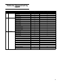
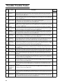
3/2015 Installation Guide & User Manual About This Manual This manual was written to help you understand all of the functions and capabilities of the Yamaha Snowmobile Diagnostic Tool in order for you to receive the maximum benefits from the diagnostic tool. Introduction The diagnostic tool was designed as a workshop service and diagnostic tool for diagnosis and testing of Engine Control Systems and related components. This tool provides a tremendous amount of information including: • Diagnostic Trouble Codes (DTC) • Engine Sensor Data • Fuel Injection System Control Data • Engine Controller Identification Information • Online and Offline capable • Live System Updates The diagnostic tool is a very robust diagnostic tool designed to provide diagnostic capabilities on Yamaha snowmobiles with onboard diagnostic ports. Additional vehicles and functions will be added to future updates to the software. 1 Table of Contents Vehicles Supported by YSDT ...................................................................................................3 Safety Guidelines ......................................................................................................................4 Kit Contents ...............................................................................................................................4 Installing the Software ..............................................................................................................5 Logging In ..................................................................................................................................6 Using the Yamaha Snowmobile Diagnostic Tool Software ...................................................7 Icons ...........................................................................................................................................7 Screens ......................................................................................................................................8 IDENTIFY Screen ............................................................................................................8 TROUBLE CODES Screen .............................................................................................9 Possible Trouble Codes ............................................................................................... 10 SENSOR DATA Screen .................................................................................................13 Available Sensors......................................................................................................... 14 TESTS Screen ...............................................................................................................15 Output Drivers Tab ....................................................................................................... 16 ECU UPDATE Screen.................................................................................................... 17 SYSTEM SETUP Screen............................................................................................... 18 Updating the Software ............................................................................................................ 19 Uninstalling the Software ....................................................................................................... 19 2 Vehicles Supported by YSDT Year Product Line 2014 Snowmobile 2015 Snowmobile 2016 Snowmobile Model SRViper SRViper R-TX SE SRViper L-TX SRViper L-TX SE SRViper X-TX SE SRViper R-TX LE SRViper R-TX SE SRViper R-TX DX SRViper L-TX LE SRViper L-TX SE SRViper L-TX DX SRViper X-TX LE SRViper X-TX SE SRViper S-TX DX SRViper M-TX 162 LE SRViper M-TX 162 SE SRViper M-TX 153 SE SRViper M-TX 153 SRViper R-TX LE SRViper R-TX SE SRViper R-TX DX SRViper L-TX LE SRViper L-TX SE SRViper L-TX DX SRViper X-TX LE SRViper X-TX SE SRViper M-TX 162 LE SRViper M-TX 153 LE SRViper M-TX 162 SE SRViper M-TX 153 SE SRViper M-TX 141 SE SRViper M-TX 162 SRViper M-TX 153 SRViper S-TX DX 146 SRViper S-TX DX 137 ECM Diagnostics ECM Update Programing Capable X X X X X X X X X X X X X X X X X X X X X X X X X X X X X X X X X X X X X X X X X X X X X X X X X X X X X X X X X X X X X X X X X X X X X X 3 Safety Guidelines Kit Contents This safety section contains information that must be followed to avoid damage to the YSDT diagnostic tool or serious injury or death to the user. Please acknowledge this section – read it carefully. Included with your kit you will find the following parts. If replacement parts are needed, order using the following part numbers. • Thoroughly read and understand this manual before using the tool. • Diagnostics Tool – Hardware Interface to connect Laptop or PC to vehicle (must order complete kit to replace Hardware Interface) • Always make sure the diagnostic connections are clean, dry, and in good condition before connecting to a vehicle. • Diagnostics Cable (2.0 USB) – Connects the Laptop or PC to the tool • Verify the vehicle battery is fully charged and in good condition before attempting to use the diagnostic tool. Low battery voltage WILL cause communication issues as well as produce invalid test results. ! WARNING Always make sure an approved exhaust ventilation system is in place and being used. Ensure the work area being used is well ventilated whenever running an engine. Carbon monoxide gas is extremely poisonous and can lead to serious injury or death. ! WARNING Always stay clear of moving parts and remove all loose clothing that can be caught in moving parts on the vehicle. ! WARNING Always wear approved safety glasses or goggles as necessary. ! WARNING Use extreme caution when working around batteries. Batteries can produce a highly explosive hydrogen gas that can cause the battery to explode without warning. CAUTION Always make sure diagnostic cables are free and clear of any belts, pulleys, or other moving parts on the vehicle being tested. CAUTION Be sure diagnostic cables DO NOT come in contact with hot engine components such as exhaust manifold or engine block. CAUTION Never allow diagnostic cables to lay near or on any ignition system components such as coils, spark plug wires, or solenoids as electrical interference may occur and may cause damage to the diagnostic tool and/or computer. CAUTION Never allow cables to lay on the floor near or in puddles of water. Water may leak into the diagnostic connectors and cause serious damage. 4 • Diagnostics Harness (10 Pin) – For use on Snowmobiles with a 10-pin diagnostic connector • Diagnostics Filter Harness – Suppresses starter motor power feedback during starting when using the tool. To be used if tool stops functioning during vehicle starting cycles NOTE: The starter motor power feedback is not harmful to the tool. • Quick Start Manual/Guide • Diagnostic Tool Bag Installing the Software Computer Requirements Before installing the software, ensure your computer meets the following requirements: • Computer – Laptop computer (recommended) or PC in service/shop area. • Operating System – Windows XP (SP3), Windows 7, Windows 8; 4 GB RAM (min), dual core processor (recommended). NOTE: Windows Vista and Windows 8 RT will not be supported. • Internet Connection - required for installation and certain features. Installation Instructions YSDTC Choose a Start Menu folder for the Yamaha Snowmobile Diagnostic Tool shortcuts. The window will default to creating a new folder called “Yamaha Snowmobile Diagnostic Tool” as shown in the text box. Either accept this option and create a new folder, change the text and create a new folder with a different name, select a different folder from the list box, or click the “Do not create shortcuts” check box. Select the “Install” button to continue. Locate the Diagnostic Tool link as provided by your Yamaha distributor and click to install the software. When the install process has started, the Setup Wizard window will appear. Select the “Next >” button to begin. YSDTD The next screen shows the installation progress. Wait while Yamaha Snowmobile Diagnostic Tool installs. YSDTA The next screen will ask for which users to install. Select one of the options; then select the “Next >” button to continue. YSDTE YSDTB Choose a location to install. The default, recommended location will be displayed within the “Destination Folder” text box. Either accept this option or select the “Browse…” button and select a different destination folder. Select the “Next >” button to continue. 5 Once the process is complete, the following screen will be shown. Select the “Next >” button to continue. Logging In Once the Yamaha Snowmobile Diagnostic Tool application is run or has finished initializing, the following window will appear. Your Yamaha distributor will supply the “user name”, “password” and “dealer number”. Enter your dealership’s user name and password and select the “CONTINUE” button. YSDTF Finally, the Setup Wizard screen will be shown confirming the Yamaha Snowmobile Diagnostic Tool has been installed. Select the “Finish” button to close the Setup Wizard. The YSDT application will launch automatically. YSDTH Next, enter your dealer number and select the “Next” button to continue. YSDTG YSDTI Finally, enter the information as prompted in the corresponding text boxes. Select the “OK” button to finish the log-in process. If your dealership has previously registered, the following information will be automatically populated. If the information populated is incorrect, the wrong dealer number may have been used. Click the “Back” button to go back and enter the correct dealer number. Otherwise make changes and click the “OK” button. YSDTJ 6 Using the Yamaha Snowmobile Diagnostic Tool Software Connecting the YSDT to the Vehicle First, connect the receiver end of the diagnostic cable into the corresponding plug end of the YSDT; then plug the other end of the diagnostic cable into the appropriate diagnostic connector of the vehicle. YSDTN If not previously logged in, refer to “Logging In”. Icons NOTE: The icons are at the bottom of the application window. Show / Hide left-side tool bar / Internet Not Connected / Icon Disappears when Internet connection is present YSDTK Next, plug the type B USB 2.0 connector into the YSDT and the type A USB 2.0 connector into the computer. USB not connected / USB connected / No vehicle connected / Vehicle connected / / / YSDTL Engine ECM not connected / Engine ECM connected Instrument cluster not connected / Instrument cluster connected The vehicle model and VIN may be displayed at the bottom of the window. The complete setup should look like the following picture. YSDTM 1Y If previously logged in, the following initial window will appear. Select “OPEN LAST CASE” to load the last vehicle selected; otherwise select “OPEN NEW CASE”. 7 Screens IDENTIFY Screen NOTE: The screens toolbar is on the left side of the application window. When the YSDT software is opened, the default screen is the IDENTIFY screen. There are two tabs within this screen. The default tab is “VEHICLE SELECTION”; there are several options to identify a vehicle. The IDENTIFY screen is used to connect to the vehicle and view ECU ID information. The TROUBLE CODES screen is used to view and reset active/inactive codes. The SENSOR DATA screen is used to view values of vehicle sensors. The TESTS screen is used to activate/ deactivate specific vehicle functions. The ECU UPDATE screen is used if a calibration upgrade/update is available. The SYSTEM SETUP screen is used to change user settings/preferences. NOTE: Make sure the vehicle key is turned to the ON position, YSDT is connected to the vehicle and Laptop or PC with the proper harness, and the vehicle’s battery is fully charged prior to making a selection. Option 1 Click the “AUTO IDENTIFICATION” button. This will automatically select the appropriate vehicle and populate the text box with the VIN of the vehicle. NOTE: Some vehicles do not support this feature. Option 2 Enter the complete VIN (17 characters) of the vehicle in the text box and click the “CONTINUE WITH VIN” button. Option 3 Select a product from the “PRODUCT LINE” drop down list, select a year from the “MODEL YEAR” drop down list, and select a vehicle from the “VEHICLE” drop down list. 2Y NOTE: Some screens/functions may not be applicable to all models. 1Y If you click on the “ECUID” tab you can view ECU information retrieved from the vehicle. To select which ECU information is displayed make a selection from the drop down list. Types of ECU’s Engine Control Module (ECM) Instrument Cluster 8 YSDTO TROUBLE CODES Screen YSDTQ Under the “FREEZE FRAME” tab, you can view sensor data values of when the trouble code was activated. This displays data for all sensors applicable for the vehicle being serviced. Scroll through the list of sensors using the scrolling bars on the side and bottom of the screen. When the TROUBLE CODES screen is opened, the default tab opened is “TROUBLE CODES”. This tab will display Active and Inactive trouble codes on compatible models; you can also clear Inactive trouble codes. The icon displayed next to the code indicates which ECU is producing the trouble code. The status of the trouble code will also be displayed on the right side of the screen. (ECM) Engine Control Module Code Instrument Cluster Code Click the “CLEAR TROUBLE CODES” button to remove all inactive troubles codes from the tool display and from the vehicle. YSDTR NOTE: If a code has been activated multiple times, the information displayed will be from the most current code activation. YSDTP To view the details of a Trouble Code, click on the code or click the “TROUBLE CODE DETAIL” tab. Under this tab, you can view a description of the fault, a possible cause of the fault, and how to clear the code. 9 Possible Trouble Codes Code Fault Description P0031 O2 Heater Control A low voltage condition has been detected on the O2 heater control output. It is possible that the O2 Circuit Low heater or it interconnect harness is shorted to chassis ground. To clear the fault code correct the O2 Heater Control circuit condition and then turn the key to the OFF position (for a minimum of 10 seconds) then turn the key to the ON position. P0032 O2 Heater Control A high voltage condition has been detected on the O2 heater control output. It is possible that the O2 Circuit High heater or it interconnect harness is shorted to battery power. To clear the fault code correct the O2 Heater Control circuit condition and then turn the key to the OFF position (for a minimum of 10 seconds) then turn the key to the ON position. P0107 Manifold Absolute A low voltage condition has been detected on the manifold absolute pressure sensor input. It is possible Pressure Circuit the MAP sensor or its interconnect harness is open or shorted to chassis ground. Low To clear the fault code correct the MAP sensor circuit condition and then turn the key to the OFF position (for a minimum of 10 seconds) then turn the key to the ON position. P0108 Manifold Absolute A high voltage condition has been detected on the manifold absolute pressure sensor input. It is possible Pressure Circuit the MAP sensor or its interconnect harness is shorted to battery power. To clear the fault code correct the High MAP sensor circuit condition and then turn the key to the OFF position (for a minimum of 10 seconds) then turn the key to the ON position. P0112 Intake Air A low voltage condition has been detected on the intake air temperature sensor input. It is possible the Temperature intake air temperature sensor or its interconnect harness is open or shorted to chassis ground. To clear Sensor Circuit Low the fault code correct the intake air temperature sensor circuit condition and then turn the key to the OFF position (for a minimum of 10 seconds) then turn the key to the ON position. P0113 Intake Air A high voltage condition has been detected on the intake air temperature sensor input. It is possible the Temperature intake air temperature sensor or its interconnect harness is shorted to battery power. To clear the fault Sensor Circuit High code correct the intake air temperature sensor circuit condition and then turn the key to the OFF position (for a minimum of 10 seconds) then turn the key to the ON position. P0115 Engine Coolant A constant voltage condition has been detected on the engine coolant temperature sensor input. It is Temperature possible the engine coolant temperature sensor is faulty or the thermostat may be stuck. To clear the fault Sensor 1 Circuit code correct the engine coolant temperature sensor circuit condition and then turn the key to the OFF position (for a minimum of 10 seconds) then turn the key to the ON position. P0117 Engine Coolant To clear the fault code correct the engine coolant temperature sensor circuit condition and then turn the Temperature key to the OFF position (for a minimum of 10 seconds) then turn the key to the ON position.A low voltage Sensor 1 Circuit condition has been detected on the engine coolant temperature sensor input. It is possible the engine Low coolant temperature sensor or its interconnect harness is open or shorted to chassis ground. P0118 Engine Coolant A high voltage condition has been detected on the engine coolant temperature sensor input. It is possible Temperature the engine coolant temperature sensor or its interconnect harness is shorted to battery power. To clear the Sensor 1 Circuit fault code correct the engine coolant temperature sensor circuit condition and then turn the key to the OFF High position (for a minimum of 10 seconds) then turn the key to the ON position. P0120 Throttle Position This code will be set any time an error has occurred in the TPS circuit. The TPS or its interconnect Sensor Circuit harness is open, shorted to ground or shorted to battery power. To clear the fault code correct the TPS circuit condition and then turn the key to the OFF position (for a minimum of 10 seconds) then turn the key to the ON position. P0122 Throttle Position A low voltage condition has been detected on the TPS input. It is possible the TPS or its interconnect Sensor Circuit Low harness is open or shorted to chassis ground. To clear the fault code correct the TPS circuit condition and then turn the key to the OFF position (for a minimum of 10 seconds) then turn the key to the ON position. P0123 Throttle Position A high voltage condition has been detected on the TPS input. It is possible the TPS or its interconnect Sensor Circuit High harness is shorted to battery power. To clear the fault code correct the throttle position sensor circuit condition and then turn the key to the OFF position (for a minimum of 10 seconds) then turn the key to the ON position. P0130 O2 Sensor Circuit An intermittent open or open circuit condition has been detected on the O2 sensor input. It is possible that the O2 sensor or its interconnect harness have an intermittent open or an open circuit. To clear the fault code correct the O2 sensor circuit condition and then turn the key to the OFF position (for a minimum of 10 seconds) then turn the key to the ON position. P0131 O2 Sensor Circuit A low voltage condition has been detected on the O2 sensor input. It is possible the O2 sensor or its Low interconnect harness is shorted to chassis ground or an air leak may exist in the exhaust. To clear the fault code correct the O2 sensor circuit condition and then turn the key to the OFF position (for a minimum of 10 seconds) then turn the key to the ON position. P0132 O2 Sensor Circuit A high voltage condition has been detected on the O2 sensor input. It is possible the O2 sensor or its High interconnect harness is shorted to battery power. To clear the fault code correct the O2 sensor circuit condition and then turn the key to the OFF position (for a minimum of 10 seconds) then turn the key to the ON position. P0171 System Too Lean It is possible that this symptom is caused by low fuel pressure, dirty fuel filter or dirty injectors. To clear the The ECM internal fault code correct the lean condition and then turn the key to the OFF position (for a minimum of 10 O2 feedback is seconds) then turn the key to the ON position. lower than expected. P0172 System Too Rich The ECM internal O2 feedback is higher than expected. It is possible that this symptom is caused by excessive fuel pressure, faulty MAP sensor or faulty temp sensors. To clear the fault code correct the rich condition and then turn the key to the OFF position (for a minimum of 10 seconds) then turn the key to the ON position. P0201 Injector Circuit/ An intermittent open or open circuit condition has been detected on the fuel injector circuit, PTO side Open Cylinder 1 cylinder. It is possible that the injector or its interconnect harness have an intermittent open or an open circuit. To clear the fault code correct the injector circuit condition and then turn the key to the OFF position (for a minimum of 10 seconds) then turn the key to the ON position. 10 Applicable Models SR Viper X X X X X X X X X X X X X X X X X X Code P0202 P0203 P0217 P0261 P0264 P0267 P0508 P0509 P0511 P0522 P0523 P0562 P0563 P0780 P1315 P1338 P1339 P1685 P1686 Applicable Models SR Viper Injector Circuit/ An intermittent open or open circuit condition has been detected on the fuel injector circuit, center cylinder. X Open Cylinder 2 It is possible that the injector or its interconnect harness have an intermittent open or an open circuit. To clear the fault code correct the injector circuit condition and then turn the key to the OFF position (for a minimum of 10 seconds) then turn the key to the ON position. Injector Circuit/ An intermittent open or open circuit condition has been detected on the fuel injector circuit, MAG side X Open Cylinder 3 cylinder. It is possible that the injector or its interconnect harness have an intermittent open or an open circuit. To clear the fault code correct the injector circuit condition and then turn the key to the OFF position (for a minimum of 10 seconds) then turn the key to the ON position. Engine Coolant The engine coolant temperature is too high for engine operation. Possible causes for this code are poor X Over Temperature snow conditions, engine coolant level is low or the water pump may not be circulating coolant properly. To Condition clear the fault code correct the engine coolant over temperature condition and then turn the key to the OFF position (for a minimum of 10 seconds) then turn the key to the ON position. Cylinder 1 Injector A low voltage condition has been detected on the injector circuit output, for the PTO side cylinder. It is X Circuit Low possible the injector or its interconnect harness is shorted to chassis ground. To clear the fault code correct the injector circuit condition and then turn the key to the OFF position (for a minimum of 10 seconds) then turn the key to the ON position. Cylinder 2 Injector A low voltage condition has been detected on the injector circuit output, for the center cylinder. It is X Circuit Low possible the injector or its interconnect harness is shorted to chassis ground. To clear the fault code correct the injector circuit condition and then turn the key to the OFF position (for a minimum of 10 seconds) then turn the key to the ON position. Cylinder 3 Injector A low voltage condition has been detected on the injector circuit output, for the MAG side cylinder. It is X Circuit Low possible the injector or its interconnect harness is shorted to chassis ground. To clear the fault code correct the injector circuit condition and then turn the key to the OFF position (for a minimum of 10 seconds) then turn the key to the ON position. Idle Air Control A low voltage condition has been detected on the ISC control circuit. It is possible the ISC or its X System Circuit Low interconnect harness is shorted to chassis ground. To clear the fault code correct the ISC circuit condition and then turn the key to the OFF position (for a minimum of 10 seconds) then turn the key to the ON position. Idle Air Control A high voltage condition has been detected on the ISC control circuit. It is possible the ISC or its X System Circuit High interconnect harness is shorted to battery power. To clear the fault code correct the ISC circuit condition and then turn the key to the OFF position (for a minimum of 10 seconds) then turn the key to the ON position. Idle Air Control An open circuit condition has been detected on the ISC control circuit. It is possible the ISC or its X System Circuit interconnect harness is open. To clear the fault code correct the ISC circuit condition and then turn the key to the OFF position (for a minimum of 10 seconds) then turn the key to the ON position. Engine Oil A low voltage condition has been detected on the engine oil pressure sensor input circuit. It is possible the X Pressure Sensor engine oil pressure sensor or its interconnect harness is open or shorted to chassis ground. To clear the Circuit Low fault code correct the engine oil pressure sensor circuit condition and then turn the key to the OFF position (for a minimum of 10 seconds) then turn the key to the ON position. Engine Oil A high voltage condition has been detected on the engine oil pressure sensor input circuit. It is possible X Pressure Sensor the engine oil pressure sensor or its interconnect harness is shorted to battery power. To clear the fault Circuit High code correct the engine oil pressure sensor circuit condition and then turn the key to the OFF position (for a minimum of 10 seconds) then turn the key to the ON position. System Voltage A low voltage condition has been detected on the system power circuit. It is possible the regulator/rectifier X Low output or the battery charge condition is low. To clear the fault code correct the battery charging circuit condition and then turn the key to the OFF position (for a minimum of 10 seconds) then turn the key to the ON position. System Voltage A high voltage condition has been detected on the system power circuit. It is possible the regulator/rectifier X High output is high or the battery cable connections may be loose. To clear the fault code correct the battery charging circuit condition and then turn the key to the OFF position (for a minimum of 10 seconds) then turn the key to the ON position. Shift Error A gear change was not detected when the command was given to change gears. It is possible the reverse X actuator, forward relay, reverse relay or gear position switch may be faulty or not connected. To clear the fault code verify that the relays are activating the reverse actuator and gear position switch when an attempt is made, then turn the key to the OFF position (for a minimum of 10 seconds) then turn the key to the ON position. X Crankshaft Position The ECM was unable to determine the crankshaft position from the signal given by the crankshaft position Out of Sync sensor. It is possible that the crankshaft position sensor is faulty or the CPS may have debris on it causing a poor signal. Before replacing the CPS verify that the battery is in good health, connections from the battery to the starter are tight, and that the engine is turning over properly. To clear the fault code correct the crankshaft position out of sync condition and then turn the key to the OFF position (for a minimum of 10 seconds) then turn the key to the ON position. Crankshaft Spike The ECM has detected an abnormal spike in the signal from the CPS. It is possible that the signal from the X Detected CPS to the ECM is intermittent or the signal is out of the defined parameters due to inconsistent cranking speed, improper combustion or a faulty CPS sensor. To clear the fault code correct the crankshaft spike detected condition and then turn the key to the OFF position (for a minimum of 10 seconds) then turn the key to the ON position. Crankshaft Tooth The ECM has detected an incorrect number of teeth in the signal sent from the CPS. It is possible that the X Not Detected air gap from the CPS to the timing gear on the output shaft assembly is out of specification, the CPS is reading an incorrect number of teeth due to debris on the CPS or CPS is faulty. To clear the fault code correct the crankshaft tooth not detected condition and then turn the key to the OFF position (for a minimum of 10 seconds) then turn the key to the ON position. Main Relay Open An open circuit has been detected on the coil side of the ISC relay. It is possible that the ISC relay in the X Circuit PDM is not making connection or the wiring to the ISC relay is open due to a broken wire. To clear the fault code correct the main relay open circuit condition and then turn the key to the OFF position (for a minimum of 10 seconds) then turn the key to the ON position. Main Relay Circuit A low voltage condition has been detected on the coil side of the ISC relay. It is possible that the ISC relay X Low in the PDM or its interconnect harness is shorted to chassis ground. To clear the fault code correct the main relay circuit low condition and then turn the key to the OFF position (for a minimum of 10 seconds) then turn the key to the ON position. Fault Description 11 Code P1688 P1689 P1691 P1692 P1694 P1695 P2228 P2229 P2300 P2303 P2306 U0155 U1000 U1001 12 Applicable Models SR Viper Reverse Relay An open circuit has been detected on the coil side of the reverse relay. It is possible that the reverse relay X Open Circuit in the PDM is not making connection or the wiring to the reverse relay is open due to a broken wire. To clear the fault code correct the reverse relay open circuit condition and then turn the key to the OFF position (for a minimum of 10 seconds) then turn the key to the ON position. Reverse Relay A low voltage condition has been detected on the coil side of the reverse relay. It is possible that the X Circuit Low reverse relay in the PDM or its interconnect harness is shorted to chassis ground. To clear the fault code correct the reverse relay circuit low condition and then turn the key to the OFF position (for a minimum of 10 seconds) then turn the key to the ON position. Forward Relay An open circuit has been detected on the coil side of the forward relay. It is possible that the forward relay X Open Circuit in the PDM is not making connection or the wiring to the forward relay is open due to a broken wire. To clear the fault code correct the forward relay open circuit condition and then turn the key to the OFF position (for a minimum of 10 seconds) then turn the key to the ON position. Forward Relay A low voltage condition has been detected on the coil side of the forward relay. It is possible that the X Circuit Low forward relay in the PDM or its interconnect harness is shorted to chassis ground. To clear the fault code correct the forward relay circuit low condition and then turn the key to the OFF position (for a minimum of 10 seconds) then turn the key to the ON position. Headlight Relay An open circuit has been detected on the coil side of the headlight relay. It is possible that the headlight X Open Circuit relay in the PDM is not making connection or the wiring to the headlight relay is open due to a broken wire. To clear the fault code correct the headlight relay open circuit condition and then turn the key to the OFF position (for a minimum of 10 seconds) then turn the key to the ON position. Headlight Relay A low voltage condition has been detected on the coil side of the headlight relay. It is possible that the X Circuit Low headlight relay in the PDM or its interconnect harness is shorted to chassis ground. To clear the fault code correct the headlight relay circuit low condition and then turn the key to the OFF position (for a minimum of 10 seconds) then turn the key to the ON position. Barometric A low voltage condition has been detected on the barometric pressure sensor input. It is possible the X Pressure Sensor barometric pressure sensor or its interconnect harness is open or shorted to chassis ground. To clear the “A” Circuit Low fault code correct the barometric pressure sensor circuit condition and then turn the key to the OFF position (for a minimum of 10 seconds) then turn the key to the ON position. Barometric A high voltage condition has been detected on the barometric pressure sensor input. It is possible the X Pressure Sensor barometric pressure sensor or its interconnect harness is open or shorted to battery power. To clear the “A” Circuit High fault code correct the barometric pressure sensor circuit condition and then turn the key to the OFF position (for a minimum of 10 seconds) then turn the key to the ON position. Ignition Coil “A” A low voltage condition has been detected on the PTO side cylinder ignition coil. It is possible the ignition X Primary Control coil or its interconnect harness is open or shorted to chassis ground. To clear the fault code correct ignition Circuit Low coil “A” primary control circuit low condition and then turn the key to the OFF position (for a minimum of 10 seconds) then turn the key to the ON position. Ignition Coil “B” A low voltage condition has been detected on the center cylinder ignition coil. It is possible the ignition coil X Primary Control or its interconnect harness is open or shorted to chassis ground. To clear the fault code correct ignition coil Circuit Low “B” primary control circuit low condition and then turn the key to the OFF position (for a minimum of 10 seconds) then turn the key to the ON position. Ignition Coil “C” A low voltage condition has been detected on the MAG side cylinder ignition coil. It is possible the ignition X Primary Control coil or its interconnect harness is open or shorted to chassis ground. To clear the fault code correct ignition Circuit Low coil “C” primary control circuit low condition and then turn the key to the OFF position (for a minimum of 10 seconds) then turn the key to the ON position. Lost The CAN communication between the gauge and the ECM is intermittent or has failed. It is possible that X Communication the CAN communication wires from the gauge or to the ECM are open or shorted to each other. To clear With the Gauge the fault code correct the Lost communication with gauge condition and then turn the key to the OFF position (for a minimum of 10 seconds) then turn the key to the ON position. Vehicle Not The vehicle has not been registered or had the correct PIN entered. The vehicle must be warranty X Registered or registered before the correct PIN will be supplied. To clear the fault code correct the vehicle not registered Invalid Pin Entered or invalid pin entered condition and then turn the key to the OFF position (for a minimum of 10 seconds) then turn the key to the ON position. Note: If this code is active please contact your Yamaha Distributor. X Vehicle Not The vehicle has not been registered or had the correct PIN entered and the engine hours have exceeded Registered and the allowable time. The vehicle must be warranty registered before the correct PIN will be supplied. To clear the fault code correct the vehicle not registered vehicle limits enabled condition and then turn the key Vehicle Limits to the OFF position (for a minimum of 10 seconds) then turn the key to the ON position. Enabled Note: If this code is active please contact your Yamaha Distributor. Fault Description SENSOR DATA Screen When the SENSOR DATA Screen is opened, the default tab is “SENSOR DATA”. Under this tab, you can view voltage or physical values for various sensors on the vehicle being serviced. When this tab is opened, a default list of sensors is displayed. You can add or remove sensors by using the “+” or “-” buttons in the lower-right corner of the screen. Once you have the desired sensors displayed, you can save this list for future use by clicking the “SAVE SET” button. You will be prompted to enter a name for the set. To open previously saved sets, click the “LOAD SET” button and choose the desired set from the list. Click the “CLEAR LIST” button to remove all items from the display. YSDTU Each sensor is displayed on a separate axis on the right or left side of the graph. By default, the lower and upper values are set to the minimum and maximum allowable value for the sensor on that axis. To zoom within the default range, highlight the area by clicking and holding the left mouse button on the axis you wish to zoom. Once you have the desired range of values highlighted, release the left mouse button and it will zoom to the selected values. To return to the default range of values, double click within the axis. YSDTS A sensor value can be viewed in full-screen mode by clicking the expand icon ( ) located at the far right position of a sensor’s row. This opens the full screen in a new window. To exit full-screen mode, click the “X” in the upper-right corner of the screen. 3Y Sensor data can also be displayed with gauges by clicking the “METERS” tab. When the “METERS” tab is opened, a default list of meters are displayed. This can be changed by clicking the “+” or “-” buttons in the lower right side of the screen. Once you have the desired meters displayed, you can save this list for future use by clicking the “SAVE SET” button. Type a name for the set you are saving. To open previously saved sets, click the “LOAD SET” button and choose the desired set from the list. Click the “CLEAR” button to remove all items from the display. YSDTT A sensor can be viewed graphically by clicking the graph icon ( ) located at the far-right position of a sensor’s row. This will open the “CHARTS” tab and allow for up to four sensors to be shown graphically by selecting them from the drop down lists located on the right side of the screen. With the “CHARTS” tab selected, the graph will begin displaying values for the sensors selected. Click the “PAUSE GRAPH” to stop displaying values of the sensors. With the graph paused, you can scroll through the data by using the sliding icon in “GRAPH HISTORY”. Click the “RESUME GRAPH” to continue displaying data. YSDTV NOTE: The type of gauge displayed can be changed by double clicking the sensor’s gauge. 13 Available Sensors Sensor Name Engine Run Time Sensor Description Sensor Output Value Overall Engine Operating Time Displays the accrued time on the engine in hours. Degrees of TPS Open Angle of throttle plate. Displays the position of the TPS in degrees. Ambient Air Pressure Ambient Air Pressure Displays the value of the atmospheric pressure in in.-HG or mb depending on units selected in user preferences. Air Temperature Sensor Value of Air Temperature Sensor Displays the value of the intake air temperature in °F or °C depending on units selected in user preferences. Relay Battery Voltage Voltage to ECM Displays the voltage supplied to the ECM from the main relay. If this voltage is not very close to the Battery Voltage - Key On it may indicate an issue with the circuit. Coolant Temperature Sensor Value of coolant temperature Displays the value of the coolant temperature in °F or °C depending on units selected in user preferences. Vehicle Speed Miles/Kilometers Per Hour Displays the track speed in MPH or KMH depending on units selected in user preferences. Idle RPM Target RPM at operating temperature. Displays the target idle speed determined by the ECM. This value is dependent on engine coolant temperature and will change as the engine reaches operating temperature. Engine Overheat Engine Hot Displays the current state of the engine coolant temperature. “Good” will be displayed if the engine coolant temperature is below 221°F or 105°C. “Hot” will be displayed if the engine coolant temperature is above 221°F or 105°C. Low Oil Pressure Reading from oil pressure Displays the current state of oil pressure by inputs to the ECM from the oil pressure switch switch or an analog sensor or the oil pressure sensor. “Good will be displayed if the ECM detects adequate oil at specific RPMs pressure and “Low” will be displayed if the ECM detects a low oil pressure condition exists. Gear Position Forward/Reverse Displays the current direction of travel dependent on the gear position switch. RPM Limit Rev Limiter Set point Displays the current RPM Limit set point determined by inputs to the ECM. RPS Engine Control Runaway Prevention Switch Displays the current status of the RPS Engine Control strategy. If all systems are operating correctly “INACTIVE” will be displayed. If the system determines the engine needs to be shutdown “ACTIVE” will be displayed. ISC Idle Speed Control (ISC) Displays the current target position of the ISC determined by the ECM, this value will be displayed in the number of steps of targeted ISC position. Warranty Registration After 5 hours of operation, engine RPM limited Displays the status of the Warranty Registration Limitation. “Limited” will be displayed if the correct PIN has not been entered and the engine hours exceed 5 hours. “Good” will be displayed if the correct PIN has been entered or the engine hours are less than 5 hours. Note: If “Limited” is displayed please contact your Yamaha Distributor. Registration Status Yes/No Displays the PIN registration status. “Not Registered” will be displayed if the PIN has not been entered. “Registered” will be displayed if the PIN has been successfully entered. Note: If “Not Registered” is displayed please contact your Yamaha Distributor. Engine RPM Revolutions Per Minute Displays the current engine RPM determined by the signal sent to the ECM from the Crankshaft Position Sensor. Battery Voltage - Key On Current Voltage of the Battery Displays the voltage supplied to the ECM from the key switch. If this voltage is not very close to the Relay Battery Voltage it may indicate an issue with the circuit. Air Temperature Sensor Voltage Displays the voltage sent to the ECM of the Air Temperature Sensor. Intake Manifold Air Pressure Sensor Voltage Displays the voltage sent to the ECM of the Intake Manifold Air Pressure Sensor. State of Oil Pressure Switch Reading from oil pressure switch at specific RPM Displays the position of the oil pressure switch. “Off” will be displayed when there is adequate pressure at the switch which creates an open circuit, there may still be a low oil pressure alarm if the oil pressure sensor detects a low oil pressure reading for current RPM. “On” will be displayed if there is inadequate oil pressure at the switch, which closes the circuit. Intake Manifold Air Pressure Intake Manifold Air Pressure Displays the value of the intake air pressure in in.-HG or mb depending on units selected in user preferences. Idle RPM Target RPM at operating temperature Displays the target idle RPM specified by the ECM. Engine coolant temperature will affect the target idle RPM, if the engine coolant temperature is below the operating temperature the target idle RPM will be higher. Engine State Engine Stop/Started/Idle Speed/Part Load/ Throttle Trailing/Trailing Throttle Fuel cutoff Displays the current engine state determined by the ECM dependent on inputs to the ECM. CPS Synchronization Crank Position Sensor Displays the current state of the CPS synchronization strategy determined by the ECM. This is used to determine engine position and timing of spark and injection. “True” will be displayed if the ECM is able to determine the position of the engine. “False” will be displayed if the ECM is not able to determine the position of the engine. Maximum Manifold Air Pressure Maximum pressure reached Displays the maximum Intake Manifold Air Pressure measured over the vehicles total run over life of vehicle time. Units displayed will be in.-HG or mb depending on units selected in user preferences. Maximum RPM Maximum RPM reached over life of vehicle Displays the maximum RPM measured over the vehicles total run time. Maximum Engine Coolant Maximum temperature Displays the maximum Engine Coolant Temperature measured over the vehicles total run Temperature reached over life of vehicle time. Units displayed will be °F or °C depending on units selected in user preferences. Maximum Intake Air Temperature 14 Maximum temperature Displays the maximum Engine Intake Temperature measured over the vehicles total run reached over life of vehicle time. Units displayed will be °F or °C depending on units selected in user preferences. TESTS Screen When the “TESTS” screen is opened, the default tab is “OUTPUT DRIVER”. This tab shows which output driver tests are available for the vehicle being serviced. This screen allows the technician to activate or deactivate certain sensors; functions will vary depending on product line and model. Select a test and click the “ACTIVATE” button to perform the test. Click the “RESET ACTIVATE” button to reset it. Click the “DEACTIVATE” button to deactivate the test. Click the “RESET DEACTIVATE” button to reset it. When the TESTS screen is opened for the first time of a session, there will be a warning message displayed. Read and understand the warning; then check “I have read and acknowledge the above WARNING statement and have complied with it” and click the “OK” button to continue. Otherwise click the “CANCEL” button which will exit you from the “TESTS” screen. 5Y NOTE: “DEACTIVATE” and “RESET DEACTIVATE” may not be applicable to the vehicle being serviced. 4Y 15 Output Drivers Tab Test Name Test Description Test Instructions Ignition Coil Repeatedly activates the MAG side ignition coil for the specified Cylinder #3 (MAG- test interval. Once the test has completed, click the “RESET” Side Cylinder) button before proceeding with the next test. NOTE: To start the vehicle after activating this test, turn the key off until it has disconnected from the tool prior to starting. With the key in the ON position and the engine off, using an appropriate spark tester, click the “ACTIVATE” button. There will be multiple triggers of the ignition coil, this will happen very rapidly. Once the test has been completed click the “RESET” button. Ignition Coil Repeatedly activates the center cylinder ignition coil for the Cylinder #2 (Center specified test interval. Once the test has completed, click the Cylinder) “RESET” button before proceeding with the next test. NOTE: To start the vehicle after activating this test, turn the key off until it has disconnected from the tool prior to starting. With the key in the ON position and the engine off, using an appropriate spark tester, click the “ACTIVATE” button. There will be multiple triggers of the ignition coil, this will happen very rapidly. Once the test has been completed click the “RESET” button. Ignition Coil Repeatedly activates the PTO side ignition coil for the specified Cylinder #1 (PTO- test interval. Once the test has completed, click the “RESET” Side Cylinder) button before proceeding with the next test. NOTE: To start the vehicle after activating this test, turn the key off until it has disconnected from the tool prior to starting. With the key in the ON position and the engine off, using an appropriate spark tester, click the “ACTIVATE” button. There will be multiple triggers of the ignition coil, this will happen very rapidly. Once the test has been completed click the “RESET” button. Fuel Pump Activates the fuel pump for the specified test interval. Listen for the fuel pump building pressure. NOTE: To start the vehicle after activating this test, turn the key off until it has disconnected from the tool prior to starting. With the key in the ON position and the engine off, click the “ACTIVATE” button, the fuel pump will cycle on and off during the specified test interval. Fuel pressure should build to the specified pressure. Once the test has been completed click the “RESET” button. Cooling Fan Activates the cooling fan from the ECM for a specified test interval. With the key in the ON position and the engine off, click the NOTE: To start the vehicle after activating this test, turn the “ACTIVATE” button, the cooling fan will cycle on and off key off until it has disconnected from the tool prior to starting. during the specified test interval. Listen to hear the fan, there will be an audible noise heard. Once the test has been completed click the “RESET” button. Vehicle Speed Test Displays the selected speed on the gauge. NOTE: To start the vehicle after activating this test, turn the key off until it has disconnected from the tool prior to starting. With the key in the ON position and the engine off, click the one of the three available speeds to be displayed, the units displayed will be determined by the units the gauge is set to. Once the test has completed click the “RESET” button. This test verifies the gauge is receiving the correct signal to display speed. Engine RPM Test Displays the selected RPM on the gauge. NOTE: To start the vehicle after activating this test, turn the key off until it has disconnected from the tool prior to starting. With the key in the ON position and the engine off, click the one of the two available RPM’s to be displayed. Once the test has completed click the “RESET” button. This test verifies the gauge is receiving the correct signal to display engine RPM. Headlight Relay Repeatedly activates the headlight relay. NOTE: To start the vehicle after activating this test, turn the key off until it has disconnected from the tool prior to starting. With the key in the ON position and the engine off, click the “ACTIVATE” button, the headlights will turn of and off for the specified test interval. Once the test has completed click the “RESET” button. This verifies the signal from the ECM is activating the relay located in the PDM, the wiring from the PDM to the headlight bulbs and the headlight bulbs. Forward Shift Relay Activates the forward shift relay. NOTE: The gear shift actuator will also activate if connected to the vehicle harness. NOTE: To start the vehicle after activating this test, turn the key off until it has disconnected from the tool prior to starting. With the key in the ON position and the engine off, click the “ACTIVATE” button, if not already in forward gear it will shift into forward gear. Once the test has completed click the “RESET” button. This verifies the signal from the ECM is activating the relay located in the PDM, the wiring from the PDM to the gear shift actuator and the gear shift actuator. Reverse Shift Relay Activates the reverse shift relay. NOTE: The gear shift actuator will also activate if connected to the vehicle harness. NOTE: To start the vehicle after activating this test, turn the key off until it has disconnected from the tool prior to starting. With the key in the ON position and the engine off, click the “ACTIVATE” button, if not already in reverse gear it will shift into reverse gear. Once the test has completed click the “RESET” button. This verifies the signal from the ECM is activating the relay located in the PDM, the wiring from the PDM to the gear shift actuator and the gear shift actuator. Idle Speed Controller (ISC) Repeatedly cycles the ISC stepper motor for the specified test interval. Listen for the ISC valve to rotate from fully open to fully closed. NOTE: To start the vehicle after activating this test, turn the key off until it has disconnected from the tool prior to starting. With the key in the ON position and the engine off, click the “ACTIVATE” button, listen to hear the ISC stepper motor moving. Once the test has been completed click the “RESET” button. This test verifies the operation and function of the ISC stepper motor. To view the target position of the ISC select the ISC on the gauge display. 16 ECU UPDATE Screen If there is an ECU update available, the following screen will appear automatically once the vehicle identification has been completed. Click the “CONTINUE” button to download the update to the ECU. 9Y If the key is not turned off, the following screen will appear. Click the “OK” button to return to the “IDENTIFY” page. 6Y A prompt to log in will appear. Enter your user name and password; then click the “CONTINUE” button to log in and proceed with the download. 10Y Once the key is turned off, the following screen will appear. Turn the key on to complete the procedure. 7Y Before the ECU update can begin, the entire file will be downloaded to your computer prior to uploading to the ECU. The following warning message will appear. Read and understand the warning message and perform any necessary tasks; then click the “OK” button to continue. 11Y If the key is not turned on, the following screen will appear. Click the “OK” button to return to the “IDENTIFY” page. 8Y When the progress bar reaches 100%, the following screen will appear. Turn the key off and wait for the next prompt. 17 SYSTEM SETUP Screen When you open the SYSTEM SETUP screen, the default tab is “DEALER INFORMATION”. From this tab, you can view and edit your contact information. If there are changes made, click the “SAVE” button before exiting this tab. 12Y Once the key is turned on, the following screen will appear. Click the “OK” button to complete the update. YSDTW Under the “SYSTEM CONFIG” tab, you can view your system configuration details. This information cannot be edited. 13Y If the “ECU UPDATE” screen is opened manually and there are no updates available, the following screen will be shown. Click the “OK” button to return to the “IDENTIFY” screen. YSDTX Under the “PREFERENCES” tab, the language and unit preferences can be viewed or edited. To edit, select your preferences from the drop down lists and click the “SAVE & RESTART” button to save the changes. The YSDT will close and restart with your new preferences. 14Y NOTE: If an update is available, refer to the beginning of this section for instruction. YSDTY 18 Updating the Software Uninstalling the Software Each time you open the YSDT software, it will automatically check for updates. If an update is found, the following screen will be shown. To begin the uninstall process, locate the Yamaha Snowmobile Diagnostic Tool folder using Windows Explorer or by opening “My Computer” and finding the file in the location you have saved it. Open the folder; then open the “Dealer Diagnostic System” folder. Double click the “UNINSTALL” application to perform the uninstall process. The uninstall application will open the following window. Click the “UNINSTALL” button to begin uninstalling. 15Y NOTE: Always update to the latest version to allow access to the latest features and models. Select either “YES” or “NO” to continue. If “YES” is selected, the update will begin. Wait for the update to download. Once the update is downloaded, the installation process must be performed again. The setup wizard will start automatically once the update has finished downloading. Refer to the “Installing the Software” portion of this manual for instructions on how to reinstall. YSDTC The next screen will show the progress of the uninstall. Wait while YSDT is uninstalled. YSDTE 16Y If “NO” is selected, the update window will close and this update screen will appear upon opening the next software session. The following screen will be displayed when the uninstall process is complete. Click the “CLOSE” button to close the uninstall application. YSDTF 19