1
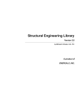
EnR Solutions, LLC Quick User’s Manual SSS 2.1 COPYRIGHT The software program SSS version 2.1 and all its associated documentation are proprietary and copyrighted products. Worldwide rights of ownership rest with EnR Solutions, LLC. Unlicensed use of the program or reproduction of the documentation in any form, without prior written authorization from EnR Solutions, LLC, is explicitly prohibited. Copyright 2002 by EnR Solutions, LLC nd 2 Edition, 2nd Printing, April 2002 Printed in USA Further information and copies of this documentation may be obtained from: Engineering & Research Solutions, LLC A Cornell Business and Technology Park Company 95 Brown Rd., Suite 1012 Ithaca, NY 14850 Tel: (607) 257-8591 Fax: (607) 257-0544 www.EnRsolutions.com Sales & Technical Support [email protected] i EnR Solutions, LLC Quick User’s Manual SSS 2.1 TABLE OF CONTENTS TABLE OF CONTENTS ..................................................................................................... II 1 INTRODUCTION........................................................................................................ 1 1.1 2 SYSTEM REQUIREMENTS AND INSTALLATION ................................................... 2 2.1 2.2 2.3 3 MAIN APPLICATIONS OF PROGRAM ......................................................... 1 SYSTEM REQUIREMENTS ............................................................................ 2 INSTALLATION GUIDE.................................................................................. 2 CONFIGURE YOUR LICENSE ....................................................................... 3 USER’S MANUAL....................................................................................................... 5 3.1 DETAILS ............................................................................................................ 5 3.1.1 Categories of Details.................................................................................. 5 3.1.2 Main Toolbar Buttons............................................................................... 6 3.2 PROJECT ........................................................................................................... 9 3.2.1 Main Menu and Toolbar Buttons ............................................................ 9 3.2.1.1 Project Menu .......................................................................................... 9 3.2.1.2 Edit Menu ............................................................................................... 9 3.2.1.3 View Menu............................................................................................ 10 3.2.1.4 Insert Menu .......................................................................................... 10 3.2.1.5 Component Menu ................................................................................. 11 3.2.2 Working a Project ................................................................................... 11 3.2.2.1 Add a New Project ................................................................................ 11 3.2.2.2 Edit Project Defaults ............................................................................ 11 3.2.2.3 Add Components .................................................................................. 16 3.2.3 Truss Edit................................................................................................. 29 3.2.3.1 Import Truss in .dxf Format ................................................................ 30 3.2.3.2 Truss Geometry Modification .............................................................. 30 3.2.3.3 Truss Load Modification...................................................................... 31 3.2.4 Stiff Wall Generator................................................................................ 32 3.2.4.1 Stiff Wall Defaults ................................................................................ 32 3.2.4.2 Generation of Stiff Wall System .......................................................... 32 3.2.4.3 Wind Pressure on Building Walls ....................................................... 34 3.2.4.4 Design of Stiff Wall System.................................................................. 34 3.2.4.5 3-D View of Stiff Wall System.............................................................. 35 3.2.5 3-D Structure Layout .............................................................................. 35 3.2.5.1 Main Tool Bar Buttons ........................................................................ 35 3.2.5.2 Insert Component into Structure Layout ............................................ 37 3.3 SPECIFICATIONS.......................................................................................... 38 3.3.1 Main Toolbar Buttons............................................................................. 38 3.4 PRODUCTS...................................................................................................... 39 3.5 UTILITIES ....................................................................................................... 40 3.5.1 Main Menu and Toolbar Buttons .......................................................... 40 ii EnR Solutions, LLC 3.5.1.1 3.5.1.2 3.5.1.3 4 Quick User’s Manual SSS 2.1 File Menu ............................................................................................. 40 Utilities Menu ....................................................................................... 41 Design Code Menu ............................................................................... 43 CONDITIONS OF USE............................................................................................. 43 iii EnR Solutions, LLC 1 Quick User’s Manual SSS 2.1 INTRODUCTION Steel Smart System version 2.1 (SSS 2.1) is a user-friendly analysis and design software for cold-formed light steel framing (LSF) systems. SSS 2.1 calculates minimum design loads acting on a building according to desired loads standard, analyzes the LSF components under action of these loads, designs the LSF components according to desired design code, and finally provides professional technical reports or CAD detailing drawings for the LSF components. 1.1 MAIN APPLICATIONS OF PROGRAM SSS 2.1 consists of five main applications: Details: About 400 LSF detailed connection solutions, given in categories such as: Curtain Wall, Load Bearing Wall, Shear Wall, and Roof Framing. Details can be downloaded in CAD formats. Project: Design of a complete building project consisting of several LSF components such as: roof trusses, roof beams, walls, floors, shear walls, and openings. Design of connections and clips of the LSF components; plus exporting corresponding CAD drawings. Specifications: Several LSF specifications and inspection reports are available for editing in Word format. Products: Details of gross and effective properties for industry standard coldformed steel stud and track cross sections. Utilities: Design and safety checks for cold-formed steel members in tension, compression, flexure, or web crippling. Design of screw and bolt connections. Calculation of wind, snow and earthquake loads on buildings of different heights and different roof shapes. 1 EnR Solutions, LLC 2 Quick User’s Manual SSS 2.1 SYSTEM REQUIREMENTS AND INSTALLATION 2.1 SYSTEM REQUIREMENTS Minimum: PC compatible computer with Pentium 233 MHz (MMX) processor. 64 MB of RAM. 100 MB of free hard disk space. Graphics card with 4 MB of RAM. MS Windows 98, Windows 2000 or Windows NT. Recommended: PC compatible computer with Pentium III 500 MHz processor. 128 MB of RAM. Graphics card with 8 MB of RAM. Graphics card supporting OpenGL technology. Screen resolution of 1024 by 768 pixels. 2.2 INSTALLATION GUIDE Installation of SSS 2.1 from the program CD requires only the following steps. If your computer is connected to a server or a network, it is recommended that you log off from the server, log in again as a local computer and start the installation on your local drive. After installation is complete, you may log in again connected to the server. The following installation steps are to be followed: Program CD: When you insert SSS CD into the CD-ROM, the CD loads into your computer automatically, and the following screen will show (Fig. 2.2-1). Start Installation: Choose the option “Install SSS2.1” to start the installation process. Follow installation instructions until asked to enter user data. Enter your user data and the program serial number. The serial number can be found on the SSS card or envelope. The serial number is an 11-digit number, and must be entered in the format (****-***-****). Continue Installation: SSS has 3 installation options; Typical, Compact, and Custom. Typical Installation installs all program components and samples. Details with format .dwf (approx. 7 MB) are installed. Details with formats .dwg and .dxf (approx. 285 MB) are not installed, but can be accessed from the CD. 2 EnR Solutions, LLC Quick User’s Manual SSS 2.1 FIGURE 2.2-1 SSS-CD FIRST SCREEN Compact Installation similar to typical installation, but without the program samples. Custom Installation allows for user preferences. Running SSS: When you run SSS 2.1 for the first time, the program will check your computer for a license. If you don’t have a prior license or a previous version of the program (version 2.0), SSS will run fully on your computer as a trial version for 30 days. If you have a previous trial version of the program (version 2.0), SSS will use the previous trial version conditions. If you have a prior license, SSS will detect your license conditions and have them function for the new version. 2.3 CONFIGURE YOUR LICENSE To configure your license configurations, press the ENTER key while the program is loading. Your current license configurations will be displayed. The message provides important information which appears: 3 EnR Solutions, LLC Quick User’s Manual SSS 2.1 FIGURE 2.3-1 LICENSE CONFIGURATIONS License Limit: The license limit statement shows the ending date of your license, such as: Unlimited license is a full copy license with unlimited time. 45 days left out of 90 shows the remaining days for the current license. Program not authorized shows that the license limit has been reached, the user did not perform the license transfer correctly, or the user altered the computer date. Contact EnR Solutions, LLC for further information. Site Code: This code is generated by SSS from the hardware data of the user’s computer. The code is used to extend or change license terms on this particular computer. The code will be required from the user ONLY if he/she wishes to buy one or more copies of our products, or alter the program installation. Site Key: This code is generated by our software security program to allow the user to alter/modify the license terms. It is provided for a specific Site Code and carries all license features and limits. If you are provided with a site key number, enter this number in the space provided and press Validate to activate your new license terms. License Transfer: If you wish to move your SSS copy to a different folder or another computer after installation, choose License on the main tool bar of the configuration window. Follow the instructions given by the program to safely transfer your license terms. Resume SSS execution: To exit the license configuration window and resume SSS execution, choose Program on the main tool bar of the configuration window, then choose Resume program execution. 4 EnR Solutions, LLC 3 Quick User’s Manual SSS 2.1 USER’S MANUAL 3.1 DETAILS The Details section includes about 400 Light Steel Framing detailed connection solutions. The user can navigate through details using different zooming options, view more than one detail in the same window, save a detail in .dwg or .dxf formats, or obtain a hard copy of the detail by printing. FIGURE 3.1-1 EXAMPLE OF A DETAIL 3.1.1 Categories of Details Detailed connection solutions are provided in eight main categories with each category divided into one or more sub-categories allowing for easy access to a desired group of details. 5 EnR Solutions, LLC Quick User’s Manual Curtain Wall One Story Wall Sections Multi Story Wall Sections Spandrel Sections Vertical Deflection Balcony / Cantilever Wall Details Windows and Doors Load Bearing Walls Wall Sections Interior Drywall One Story Sections Shear Walls One Story Sections Multi Story Sections Product Details LSF Product Sections Fasteners LSF Cover Sheet 3.1.2 SSS 2.1 Floor Framing Joist Framing Stair Openings Floor Girder Framing Roof Framing Soffit / Mansard Framing Roof Rafter Framing Roof Girder Framing Truss Framing LSF Systems Finishes Stud-Plank Mid-rise Panelized Wall Details Residential Framing LSF Floors w/ Masonry LSF Walls w/ Open Web Joist Main Toolbar Buttons FIGURE 3.1-2 MAIN TOOLBAR Listed below is a description of the function of each toolbar button of the Details part of SSS 2.1: 6 EnR Solutions, LLC Quick User’s Manual First Detail: View the first detail of the list. Previous Detail: View the previous detail of the list. Detail Number: This text box displays a view of the active detail number. Next Detail: View the next detail of the list. Last Detail: View the last detail of the list. Zoom Extents: Extend the view of the detail. Zoom Window: Zoom on a part of the detail. Zoom In: Zoom towards current view of the detail. Zoom Out: Zoom away from current view of the detail. Zoom Previous: Zoom to get the previous view of the detail. SSS 2.1 Save Detail As .dwg: Save current detail as .dwg format. Save Detail As .dxf: Save current detail as .dxf format. Details Form: Get one view in current window, otherwise, click the adjacent arrow to view one of the following: One View: Get one view in current window. Two Views: Get two views in current window. Three Views: Get three views in current window. Four Views: Get four views in current window. Print: Get a hard copy of the active detail. Layers: List of drawing layers with show/hide option. Exit: End the Details application. Pan: Move current view of the detail. 8 EnR Solutions, LLC 3.2 Quick User’s Manual SSS 2.1 PROJECT 3.2.1 Main Menu and Toolbar Buttons 3.2.1.1 Project Menu FIGURE 3.2-1 PROJECT MENU New: Generate new project. Open: Open an existing project. Save: Save current open project Save As: Save the current project as another new project. Generate 3-D Structure: Open the “Generate Structure” window Project Info: Open “Project Defaults” form. Exit: Close Project application 3.2.1.2 Edit Menu FIGURE 3.2-2 EDIT MENU Project Defaults: Edit project defaults. Loads: Edit project loads. Color Setup: Change color of joints, members, loads, etc. Font Setup: Change font for joint and member numbers, etc. Program Defaults: Change general program defaults for a new project. 9 EnR Solutions, LLC Quick User’s Manual SSS 2.1 3.2.1.3 View Menu FIGURE 3.2-3 VIEW MENU Show / Hide: Show or hide joints, joint numbers, etc. Show / Hide Tree: Show or hide tree of building components. 3.2.1.4 Insert Menu FIGURE 3.2-4 INSERT MENU Wall, Truss, Floor, Roof, Shear wall, Stiff Wall System, Window, Door: Insert a component to current project. Import Component: Import a previously designed component from another project. Import DXF Truss: Import a truss from a .dxf file format. 10 EnR Solutions, LLC Quick User’s Manual SSS 2.1 3.2.1.5 Component Menu FIGURE 3.2-5 COMPONENT MENU Open: Open an existing component. Delete: Delete an existing component. Save As: Save the component with another name. Load Combinations: Show load combination for the active component. Show Wind Loads: Show wind load analysis for trusses and roofs. Internal Force Diagram: Show the internal force diagram window for the current active component. Analysis and Design: Run the design for the active component. View Report: Show design report for the active component. Edit Geometry: Edit geometry of trusses. Update Loads: Update any changes in loads on the active component. Reset: Reset data after design. Export DXF: Export component in a .dxf file format. 3.2.2 Working a Project 3.2.2.1 Add a New Project From the Project menu click New. 3.2.2.2 Edit Project Defaults Edit the “Project Defaults” to set the default data for a project. Setting defaults will help shorten the project design time. 11 EnR Solutions, LLC Quick User’s Manual SSS 2.1 FIGURE 3.2-6 PROJECT INFORMATION FIGURE 3.2-7 OVERALL TAB In the building tab, select “Overall” tab to edit building data. 12 EnR Solutions, LLC Quick User’s Manual SSS 2.1 FIGURE 3.2-8 WALLS TAB In the “Walls” tab, enter the project default wall cross-section, dimensions, loads, deflection limits, and the wind load method for bearing wall. Set the default base material and thickness for the primary structure. FIGURE 3.2-9 FLOORS AND CEILINGS TAB In the “Floors and Ceilings” tab, enter both the project default ceiling and floor joist depth, spacing, length, bridging spacing, flange width, thickness, loads, deflection limits, sheathing material and position. 13 EnR Solutions, LLC Quick User’s Manual SSS 2.1 FIGURE 3.2-10 ROOFS AND TRUSSES TAB In the “Roofs and Trusses” tab, enter truss spacing, minimum depth and thickness for top chord, bottom chord, and web members. Enter the maximum bridging spacing for top chord, bottom chord, and webs. For “Roof” default data enter joist depth, spacing, length, bridging spacing, flange width, loads, and sheathing type and position. Select wind load method for truss and roof. FIGURE 3.2-11 OPENINGS TAB In the “Openings” tab, set the window and door default dimensions. 14 EnR Solutions, LLC Quick User’s Manual SSS 2.1 FIGURE 3.2-12 LOADS TAB In “Loads” tab, select defaults for ASCE Code along with Seismic, Wind, and Snow Factors. FIGURE 3.2-13 LOAD COMBINATIONS TAB In “Load Combinations” tab, set the default load combinations for walls, roofs and truss, and floors. 15 EnR Solutions, LLC Quick User’s Manual SSS 2.1 FIGURE 3.2-14 CODE/CROSS SECTION WINDOW Edit the “Code/Cross Section” window to set the default design code and material properties. 3.2.2.3 Add Components To add components to the project, from “Insert” menu click the name of the component you want to add (Wall, Truss, Floor, Roof, Window, or Door). 3.2.2.3.1 Wall Design FIGURE 3.2-15 WALL PATTERNS TAB Choose the desired geometry of wall studs from the available templates. For any other desired geometry, choose “General Case” option. 16 EnR Solutions, LLC Quick User’s Manual SSS 2.1 FIGURE 3.2-16 WALL CONFIGURATION WINDOW Enter the number of spans and their lengths. Next specify joint constraints. Press OK to proceed. FIGURE 3.2-17 STUD TAB Data in the above window is based on the project defaults for walls and can be edited. 17 EnR Solutions, LLC Quick User’s Manual SSS 2.1 FIGURE 3.2-18 INTERNAL FORCES (B.M.D.) OF A WALL Next, choose “Internal Force Diagrams” from “Component” menu to view analysis results, or “Analysis and Design” from same menu to do analysis and design directly. Design results are shown in “Design Data” tab, “Connections” tab, and “Support Data” tab appearing in next figures. FIGURE 3.2-19 DESIGN DATA TAB 18 EnR Solutions, LLC Quick User’s Manual SSS 2.1 FIGURE 3.2-20 CONNECTIONS TAB FIGURE 3.2-21 SUPPORT DATA TAB 19 EnR Solutions, LLC Quick User’s Manual SSS 2.1 3.2.2.3.2 Floor Design FIGURE 3.2-22 FLOOR PATTERNS TAB Choose the desired geometry of the floor component from the available templates. Types of templates are joist or built-up beam. For any other desired geometry, choose “General Case”. The next design steps are the same as for the wall component. 3.2.2.3.3 Roof Design FIGURE 3.2-23 ROOF PATTERNS WINDOW Choose the desired geometry of the roof joist component from the available templates. For any other desired geometry, choose “General Case”. The next design steps are the same as for the wall component. 20 EnR Solutions, LLC Quick User’s Manual SSS 2.1 3.2.2.3.4 Truss Design FIGURE 3.2-24 TRUSS PATTERNS WINDOW Choose the desired geometry of the truss component from the available templates. For any other desired geometry, choose “General Case”. FIGURE 3.2-25 TRUSS GENERATION WINDOW In “Truss Generation” window, enter truss dimensions then press OK. 21 EnR Solutions, LLC Quick User’s Manual SSS 2.1 FIGURE 3.2-26 TRUSS DATA TAB Data in the above window is based on the project defaults for trusses and can be edited. Next, select “Loads” tab. FIGURE 3.2-27 LOADS TAB In the Loads tab, edit loads on members, joint loads and restraints. To review truss input, select “Input Data” tab. 22 EnR Solutions, LLC Quick User’s Manual SSS 2.1 FIGURE 3.2-28 TRUSS INPUT DATA TAB Next, choose “Internal Force Diagrams” from “Component” menu to view analysis results, or “Analysis and Design” from same menu to do analysis and design directly. Design results are shown in “Design Data” tab, “Connections” tab, and “Support Data” tab appearing in next figures. FIGURE 3.2-29 TRUSS DESIGN DATA TAB 23 EnR Solutions, LLC Quick User’s Manual SSS 2.1 FIGURE 3.2-30 TRUSS CONNECTIONS TAB FIGURE 3.2-31 TRUSS SUPPORT DATA TAB 3.2.2.3.5 Opening Design Insert a separate opening (Window or Door) from the “Insert” menu. Otherwise, in the “Building Component” tree, click a wall to add an opening associated to this wall. 24 EnR Solutions, LLC Quick User’s Manual SSS 2.1 FIGURE 3.2-32 BUILDING COMPONENTS WINDOW FIGURE 3.2-33 WINDOW/DOOR OPENING DATA TAB In Opening Data tab, fill in the opening width, height, distance to left stud, sill height, opening location, and opening type. Then click adjacent stud tab. 25 EnR Solutions, LLC Quick User’s Manual SSS 2.1 FIGURE 3.2-34 ADJACENT STUD TAB In Adjacent Stud tab, fill in the adjacent stud section, stud spacing, stud height, number of span where the opening lays, jamb material and thickness. After finishing input click Close. To edit load click “Load Data” tab. To perform a design, choose “Analysis and Design” from “Component” menu. Design results are shown in “Design Data” tab, “Connections” tab, and “Support Data” tab. 3.2.2.3.6 Shear Wall Design FIGURE 3.2-35 SHEAR WALL INPUT DATA WINDOW Insert a shear wall using the “Shear Wall” icon on the main tool bar. Input the shear wall dimensions and loads (dead, live, and wind or seismic). Pressing O.K. will get to the shear wall main window. 26 EnR Solutions, LLC Quick User’s Manual SSS 2.1 FIGURE 3.2-36 SHEAR WALL MAIN WINDOW In the shear wall main window, edit stud and bridging spacing for wall where the shear wall is located. These data are used for design. Check the “Joint” and “Member” tabs for supports, loads and load cases, and buckling factors of wall members. FIGURE 3.2-37 SHEAR WALL DESIGN WINDOW In the “Section” tab of the shear wall main window, choose a preliminary section for the column, top track, bottom track, and diagonal bar of the wall. Alternatively, choose minimum depth and thickness values of all wall components (except bar). If utilizing alternative approach, choose Component / Analysis and Design from the main menu. A Design Control box appears to choose design preferences. Consider either Exact Section (chosen depth and thickness, but SSS changes number for boxed member) or Fixed Depth (chosen depth, but SSS changes thickness and number for boxed member). After design is performed, check color on Stiff Wall parts. Parts with blue color are design safe, while parts with red color are still unsafe and data (depth or thickness) needs to be modified to obtain a safe design. 27 EnR Solutions, LLC Quick User’s Manual SSS 2.1 3.2.2.3.7 Design Controls FIGURE 3.2-38 DESIGN CONTROLS WINDOW Use “Design Controls” form to set your design preferences: Exact Section Depth: Runs design searching for safe sections that exactly match the minimum, chosen section depths. In addition, a unified section is chosen for each chord member. Section Depth: Runs design searching for safe sections that are not less than the chosen minimum section depths. In addition, a unified section is chosen for each chord member. Section Area: Runs design searching for safe sections with absolute minimum areas. In addition, a unified section is chosen for each chord member. Use “Design for Web Crippling” to check section for web crippling under concentrated loads: Yes: Runs design considering web crippling. No: Runs design neglecting web crippling. Shows need for stiffeners if required. Use “Design Iterations” to set maximum number of design iterations. 28 EnR Solutions, LLC Quick User’s Manual SSS 2.1 3.2.2.3.8 Internal Force Diagrams FIGURE 3.2-39 INTERNAL FORCE DIAGRAM WINDOW Options of “Internal Force Diagrams” include: Show / hide joint numbers. Show / hide member numbers. Show / hide supports. Show un-deformed shape of component. Show deformed shape of component. Show bending moment diagram of component. Show shear force diagram of component. Show axial force diagram of component. Change scale of diagram. Choose load case number. Choose load combination number. Choose member number. 3.2.3 Truss Edit Use “Truss General Case” to generate or edit truss geometry for cases different than given templates. You can edit the geometry of any truss by choosing “Edit Geometry” from “Component” menu. 29 EnR Solutions, LLC Quick User’s Manual SSS 2.1 FIGURE 3.2-40 TRUSS GENERATE WINDOW 3.2.3.1 Import Truss in .dxf Format Click icon “DXF” to import the .dxf file. Choose file name and click “Open”. Select layers that include the truss geometry. FIGURE 3.2-41 DXF DATA READER WINDOW 3.2.3.2 Truss Geometry Modification Truss geometry modification tools include: Mirror: Create a mirror truss of active truss around a vertical axis. Merge All: Merge two or more trusses into one truss. 30 EnR Solutions, LLC Quick User’s Manual SSS 2.1 FIGURE 3.2-42 TRUSS MERGE ALL In the above figure, truss in third view is created as a mirror image of first truss view. The truss in fourth view is a merge of trusses in views 1, 2, and 3. Merge: Merge selected part of a truss with another truss, as shown in next figure. FIGURE 3.2-43 TRUSS MERGE There are other “Modify Geometry” truss tools, such as Add, Offset, Move Member, Generate and Delete Joint, Spread Sheet, Show Grid, and Grid Value. 3.2.3.3 Truss Load Modification Truss load modification includes: Show/Hide Joint Load: Show/hide load of joint. Show/Hide Member Load: Show/hide load of member. 31 EnR Solutions, LLC Quick User’s Manual SSS 2.1 Add Joint Load: Select joint by mouse click or by number, then add load in desired direction. Click update to apply your changes. Add Member Load: Select member by mouse click or by number, then add/delete load. Click update to apply your changes. 3.2.4 Stiff Wall Generator The “Stiff Wall Generator” analysis & design is a new feature in SSS 2.1. You can start the stiff wall module by choosing Insert / Stiff Wall Generator from the project main menu. 3.2.4.1 Stiff Wall Defaults FIGURE 3.2-44 STIFF WALL BUILDING DEFAULTS Building defaults for the Stiff Wall system are the same as those used in the project defaults; however, they are not editable. The form also shows the number of stories and story heights; these the user should edit. In case the LSF Stiff Wall system is used for only the upper floors of the building, edit the “SW Start from floor” box to describe this condition. This option affects the calculated lateral wind and seismic loads. Loading data and load combinations of the building can also be viewed. Load combinations can be edited, if desired. After revising and editing the project defaults, click the Close button to continue with Stiff Wall data. 3.2.4.2 Generation of Stiff Wall System To start the generation of your Stiff Wall system, choose Building / Add Pattern from the main menu to add a Stiff Wall pattern. Geometry of the pattern can be edited. 32 EnR Solutions, LLC Quick User’s Manual SSS 2.1 FIGURE 3.2-45 STIFF (SHEAR) WALL PATTERN FIGURE 3.2-46 GENERATION OF STIFF WALL SYSTEM After defining different wall patterns, choose Building / Generate Stiff Wall from the main menu to generate the wall system. This form allows you to add stiff walls to the displayed plan. The shown plan of the building is automatically updated to show added stiff walls. There are options on the lower right hand side of the form to quickly add stiff walls. You can edit the stiff wall patterns, and the wall distance by entering a number instead of “Front, Middle, or Back”. 33 EnR Solutions, LLC Quick User’s Manual SSS 2.1 3.2.4.3 Wind Pressure on Building Walls FIGURE 3.2-47 WIND PRESSURE ON BUILDING FACES To generate wind loads on your Stiff Wall system (using default building data), choose Building / Generate Wind Loads from the main menu. This action calculates wind pressures on all faces of the building; however, it does not display any data. To display the calculated wind pressures, choose Building / Show Wind Pressure from the main menu. The figure shows the wind pressure for a specific wind load case. You can toggle between different wind load cases from the combo box present in the main toolbox. 3.2.4.4 Design of Stiff Wall System FIGURE 3.2-48 STIFF WALL SYSTEM DESIGN To start analysis and design of the Stiff Wall system, choose Building / Run Analysis from the main menu. This action analyses the Stiff Wall system under calculated wind loads. After analysis is done, choose Building / Design All from the main menu to 34 EnR Solutions, LLC Quick User’s Manual SSS 2.1 start the design of the Stiff Walls. The figure shows design options in the Stiff Wall system. Choose a preliminary section for the column, top track, bottom track, and diagonal bar of the wall. Alternatively, choose minimum depth and thickness values of all wall components (except bar). Review the same data for each wall of the Stiff Wall system. After this, click the Design button on the small box next to the design form. A Design Control box appears to choose design preferences. Consider either Exact Section (chosen depth and thickness, but SSS changes number for boxed member) or Fixed Depth (chosen depth, but SSS changes thickness and number for boxed member). After design is performed, check color on Stiff Wall tree. Stiff Walls with blue color are design safe, while Stiff Walls with red color are still unsafe and data (depth or thickness) needs to be modified to obtain a safe design. 3.2.4.5 3-D View of Stiff Wall System FIGURE 3.2-49 3-D VIEW OF STIFF WALL SYSTEM To view a 3 dimensional layout of the Stiff Wall system, click on the Show 3-D view icon on the main tool bar. Change the load case from the combo box present in the toolbox, wind load forces and directions are shown on the structure. Use the navigation tools (Zoom, Pan, Rotate, and 2D views) to navigate through the Stiff Wall system. 3.2.5 3-D Structure Layout 3.2.5.1 Main Tool Bar Buttons FIGURE 3.2-50 3-D STRUCTURE MAIN TOOLBAR Zoom In: Zoom In at the structure. Zoom Out: Zoom Out at the structure. Zoom Dynamic: Zoom Dynamic at the structure. 35 EnR Solutions, LLC Quick User’s Manual SSS 2.1 Zoom Window: Zoom Window at the structure. Zoom Extents: Zoom Extents at the structure. Zoom Previous: Zoom Previous at the structure. Pan: To Pan the structure. Structure Rotate: To free rotate the structure. X-Rotate: To rotate the structure about X-axis. Y-Rotate: To rotate the structure about Y-axis. Z-Rotate: To rotate the structure about Z-axis. Modify Grid: To modify dimensions of grid. Grid On\Off: To show/hide grid. Show Global Axes: To show/hide global axes. 3-D View: To show 3-D view of the structure. Side View: To show the structure in Y-Z plane. Front View: To show the structure in X-Z plane. Top View: To show the structure in X-Y plane. Erase: To erase selected elements. Move: To move selected elements. Copy: To copy selected elements. Array: To create an array from selected elements. Select Mode: To return to “Select” mode. Select All: To select all components. Deselect All: To deselect all components. Partial View: To show required partial view. Export DXF 3D: To export .dxf file format for the 3-D structure view. Export DXF 2D: To export .dxf file format for the current 2-D structure view. Save As: To save current structure (.gui format). Show All Components: To show/hide all components of the structure. Show Walls: To show/hide all walls of the structure. Show Trusses: To show/hide all trusses of the structure. Show Roofs: To show/hide all roofs of the structure. Show Floors: To show/hide all floors of the structure. Show All Names: To show/hide names of the components of the structure. Show Walls Names: To show/hide all names of the walls of the structure. Show Trusses Names: To show/hide all names of the trusses of the structure. Show Roofs Names: To show/hide all names of the roofs of the structure. Show Floors Names: To show or hide all the names of the floors of the structure. Wall Layout: To show layout of all structure walls. 36 EnR Solutions, LLC Quick User’s Manual SSS 2.1 3.2.5.2 Insert Component into Structure Layout To insert a new component into the structure: Click the icon to show the component’s tree. Double click the required component. FIGURE 3.2-51 INSERTION DATA Select the joint number and direction of insertion, and then click at the intersection of two grid lines in the drawing pan to insert the component. Any truss, floor, or roof may be connected to the wall as follows: Double click the required component, select the joint number and direction of insertion, and click on a joint in the drawing pan to insert the component. FIGURE 3.2-52 TRUSS INSERTION 37 EnR Solutions, LLC Quick User’s Manual SSS 2.1 3.3 SPECIFICATIONS The Specification part of the program includes suggested light steel framing specifications and inspection reports based on AISI standards. FIGURE 3.3-1 SPECIFICATION SECTION 05400 3.3.1 Main Toolbar Buttons Show First Document: To view first specification document. Show Previous Document: To view previous specification document. Show Next Document: To view next specification document. Show Last Document: To view last specification document. Save as Word Document: To save current specification document as a .doc file for editing. Exit: To exit from the specifications application. 38 EnR Solutions, LLC Quick User’s Manual SSS 2.1 3.4 PRODUCTS The Products part of the program provides details of gross and effective properties for industry-standard cold-formed steel stud and track cross sections. Available section tables are standard table and AISI Manual table. Print a professional report for gross and effective properties of the desired cross sections by specifying both the start and end section record. FIGURE 3.4-1 CROSS SECTION PROPERTIES 39 EnR Solutions, LLC Quick User’s Manual SSS 2.1 3.5 UTILITIES The Utilities part of the program provides design and safety checks for cold-formed steel members in tension, compression, flexure, or web crippling, plus design of screw and bolt connections. It also provides calculations for minimum design wind, snow, and earthquake loads on buildings of different heights and different roof shapes. 3.5.1 Main Menu and Toolbar Buttons 3.5.1.1 File Menu FIGURE 3.5-1 FILE MENU Project: This option displays your recent project files (.sss). Choose a project file name to use its data (Project name, number, etc.) in your Utilities output reports. FIGURE 3.5-2 PROJECT DATA PROFILE Exit: End Utilities application and return to program start page. 40 EnR Solutions, LLC Quick User’s Manual SSS 2.1 3.5.1.2 Utilities Menu FIGURE 3.5-3 UTILITIES MENU Tension Member: Checks safety of a standard or an AISI Manual C-section subjected to tensile force. Input member data, material properties, applied tensile force, design code, and working units. SSS output data includes section status, allowable forces, and design safety factors. Compression Member: Checks safety of a standard or an AISI Manual Csection subjected to compression force. Input member data, material properties, applied compression force, design code, and working units. SSS output data includes section status, allowable forces, and design safety factors. Flexural Member: Checks safety of a standard or an AISI Manual C-section subjected to bending moment, shear force, and crippling force. Input member data, material properties, applied forces, design code, and working units. SSS output data includes section status, allowable forces, and design safety factors. Beam Column Member: Checks safety of a standard or an AISI Manual Csection subjected to bending moment and axial tensile (compression) force. Input member data, material properties, applied forces, design code, and working units. SSS output data includes section status, allowable forces, and combined force ratios. Design of Member: Design of a standard or an AISI Manual C-section subjected to a general case of loading (tensile or compression force, bending moment, shear force, and crippling force). Input member data, material properties, applied forces, required minimum dimensions, design code, and working units. SSS output data includes selected design section, allowable forces, and combined force ratios. Section Properties: Get gross and effective properties of a standard or an AISI manual C-section, plus nominal flexural, shear, and crippling strengths. Input section 41 EnR Solutions, LLC Quick User’s Manual SSS 2.1 name, material properties, design code, and working units. SSS output data includes gross and effective properties, and nominal strengths. Effective Area: Get effective area and effective section dimensions at a specified compressive stress of a standard or an AISI Manual C-section. Input section name, material properties, design code, and working units. SSS output data includes effective area and section dimensions at the specified stress, plus allowable compression forces. Wind-Low Rise Building: Calculation of minimum design wind pressures on walls and roof of a low-rise building. Input building dimensions, exposure category, wind speed, pressure coefficients, and ASCE loads standard (7-98 or 7-95). SSS output data includes calculated external pressure coefficients and design wind pressures for 8 design cases recommended by ASCE standards. Wind-Building of Any Height: Calculation of minimum design wind pressures on walls and roof of a building of any height. Input building dimensions, exposure category, wind speed, pressure coefficients, and ASCE loads standard (7-98, 7-95, or 7-93). SSS output data includes calculated external pressure coefficients, velocity pressures at different heights, and design wind pressures for cases of wind normal/parallel to ridge of building as recommended by ASCE standards. Wind-Component and Cladding: Calculation of minimum design wind pressures on component walls and roofs of a building. Input building dimensions, exposure category, wind speed, pressure coefficients, overhang type, and ASCE loads standard (7-98, 7-95, or 7-93). SSS output data includes calculated external pressure coefficients and design wind pressures for wall and different roof shapes (Gable and Hip roof, Multi-span roof, Monoslope roof, or Sawtooth roof). Seismic Load: Calculation of minimum design, static-equivalent, lateral seismic loads acting on a multi-story building. Input building dimensions, site seismic data, loads and loads percentages to be considered in seismic calculations, and ASCE loads standard (7-98, 7-95, or 7-93). SSS output data includes building “Seismic Use Group” and “Design Category”, plus calculated static-equivalent lateral loads acting on each story. Snow Load: Calculation of minimum design snow load intensity acting on the roof of a building. Input roof type and surface conditions, roof exposure data, and ground snow intensity. SSS output data includes roof “Slope Factor” and snow design intensity. Screw Connection: Design or check safety of a plate-to-plate screw connection subjected to tensile or shear force. Input applied force, screw set data, and plates (connected member) data. SSS output data includes completed screw data, connection nominal strengths, connection allowable force, and design safety factor. Bolt Connection: Design or check safety of a plate-to-plate bolt connection subjected to tensile or shear force. Input applied force, bolt set data, bolt material, and plates (connected member) data. SSS output data includes connection status and allowable force. Units: Use of American custom (English) units or Standard International units for current Utility calculations. 42 EnR Solutions, LLC Quick User’s Manual SSS 2.1 3.5.1.3 Design Code Menu FIGURE 3.5-4 DESIGN CODE MENU Allows for the choice of desired design codes for all SSS design and safety check utilities. Options include AISI design codes; LRFD and ASD 1996, LRFD and ASD 1996 with 1999 Supplement, and the Canadian S136 1994 standard. 4 CONDITIONS OF USE Steel Smart System 2.1 (SSS 2.1) has been thoroughly checked against relevant design codes and standards. Considerable effort has been invested in the development, documentation, and verification of this program. However, the user understands that no warranty, either expressed or implied, is made by EnR Solutions, LLC and any sponsor or affiliate. EnR Solutions, LLC provides such materials solely on an AS IS basis. The user understands and accepts that there are inherent risks in the application of the program and must understand the basic assumptions used in the program. The user is responsible for verifying the program results, as well as accuracy and applicability before use. EnR Solutions limits its responsibility to replacing the original disk in the event of physical defects for a period of one year from the date of purchase or shipment of the software. This program may be used at only one location at any given time. It may not be used in more than one location or machine at the same time unless a site license has been obtained. 43