Download NM70-TI USER MANUAL Preface

Transcript
Preface
Copyright
This publication, including all photographs, illustrations and software, is protected
under international copyright laws, with all rights reserved. Neither this manual, nor
any of the material contained herein, may be reproduced without written consent of
the author.
Version 1.0
Disclaimer
The information in this document is subject to change without notice. The manufacturer makes no representations or warranties with respect to the contents hereof
and specifically disclaims any implied warranties of merchantability or fitness for
any particular purpose. The manufacturer reserves the right to revise this publication and to make changes from time to time in the content hereof without obligation
of the manufacturer to notify any person of such revision or changes.
Trademark Recognition
Microsoft, MS-DOS and Windows are registered trademarks of Microsoft Corp.
MMX, Pentium, Pentium-II, Pentium-III, Celeron are registered trademarks of Intel
Corporation.
Other product names used in this manual are the properties of their respective owners
and are acknowledged.
Federal Communications Commission (FCC)
This equipment has been tested and found to comply with the limits for a Class B
digital device, pursuant to Part 15 of the FCC Rules. These limits are designed to
provide reasonable protection against harmful interference in a residential installation. This equipment generates, uses, and can radiate radio frequency energy and,
if not installed and used in accordance with the instructions, may cause harmful
interference to radio communications. However, there is no guarantee that interference will not occur in a particular installation. If this equipment does cause harmful
interference to radio or television reception, which can be determined by turning
the equipment off and on, the user is encouraged to try to correct the interference by
one or more of the following measures:
•
•
•
•
Reorient or relocate the receiving antenna
Increase the separation between the equipment and the receiver
Connect the equipment onto an outlet on a circuit different from that to
which the receiver is connected
Consult the dealer or an experienced radio/TV technician for help
Shielded interconnect cables and a shielded AC power cable must be employed with
this equipment to ensure compliance with the pertinent RF emission limits governing this device. Changes or modifications not expressly approved by the system’s
manufacturer could void the user’s authority to operate the equipment.
NM70-TI USER MANUAL
Declaration of Conformity
This device complies with part 15 of the FCC rules. Operation is subject to the following conditions:
•
This device may not cause harmful interference.
•
This device must accept any interference received, including interference
that may cause undesired operation.
This device is in conformity with the following EC/EMC directives:
Limits and methods of mesurement of radio disturbance char EN 55022
acteristics of information technology equipment
 EN 61000-3-2 Disturbances in supply systems caused
 EN 61000-3-3
Disturbances in supply systems caused by household appliances and similar electrical equipment “ Voltage fluctuations”
 EN 55024
Information technology equipment-Immunity characteristicsLimits and methods of measurement
Safety for information technology equipment including electrical business equipment
 EN 60950
 CE marking
Canadian Department of Communications
This class B digital apparatus meets all requirements of the Canadian Interferencecausing Equipment Regulations.
Cet appareil numérique de la classe B respecte toutes les exigences du Réglement
sur le matériel brouilieur du Canada.
About the Manual
The manual consists of the following:
ii
Chapter 1
Introducing the Motherboard
Describes features of the
motherboard.
 page 1
Chapter 2
Installing the Motherboard
Describes installation of
motherboard components.
 page 7
Chapter 3
Using BIOS
Provides information on using the BIOS Setup Utility.
 page 27
Chapter 4
Describes the motherboard
Using the Motherboard Software software.
 page 51
Chapter 5
Trouble Shooting
 page 55
Provides
basic
shooting tips.
NM70-TI USER MANUAL
trouble
TABLE OF CONTENTS
Preface
i
Chapter 1
1
Introducing the Motherboard
1
Introduction...........................................................................................1
Pakage Contents..................................................................................1
Specifications......................................................................................2
Motherboard Components................................................................4
I/O Ports...............................................................................................6
Chapter 2
7
Installing the Motherboard
7
Safety Precautions..............................................................................7
Installing the Motherboard in a Chassis.......................................7
Checking Jumper Settings..................................................................8
Installing Hardware...........................................................................10
Installing Memory Modules.......................................................10
Installing Add-on Cards..........................................................11
Connecting Optional Devices.................................................13
Installing a Hard Disk Drive/Optical Disk Drive/SATA Hard
Drive...........................................................................................22
Connecting Case Components........................................................23
Front Panel Header...............................................................................24
Chapter 3
27
Using BIOS
27
About the Setup Utility......................................................................27
The Standard Configuration........................ ...........................27
Entering the Setup Utility.......................................................27
Resetting the Default CMOS Values.....................................28
Using BIOS.........................................................................................28
BIOS Navigation Keys..............................................................29
Main Menu.............................................................................30
Advanced Menu......................................................................31
Chipset Menu..........................................................................41
Tweak Menu...............................................................................44
Boot Menu...............................................................................46
Security Menu.........................................................................47
Exit Menu..................................................................................48
Updating the BIOS......................................................................49
NM70-TI USER MANUAL
iii
Chapter 4
51
Using the Motherboard Software
51
Auto-installing under Windows XP/7/8...........................................51
Running Setup........................................................................51
Manual Installation..........................................................................53
Chapter 5
55
Trouble Shooting
55
Start up problems during assembly..............................................55
Start up problems after prolong use............................................56
Maintenance and care tips..............................................................56
Basic Troubleshooting Flowchart.....................................................57
iv
NM70-TI USER MANUAL
Introduction
Chapter 1
Chapter 1
Introducing the Motherboard
Thank you for choosing the NM70-TI motherboard of high performance, enhanced
function. This motherboard has Onboard ICP847/ICP807 CPU with a Thin Mini-ITX
form factor of 170 x 170 mm.
This motherboard is based on Intel® NM70 Express Chipset. It supports up to 16 GB
of system memory with dual channel DDR3 SO-DIMM 1333/1066 MHz. One optional
PCI Express x1 slot is supported. In addition, two mini PCI Express x1 slots are for
extending usage (one supports half-card, the other supports full-card.).
It implements an EHCI compliant interface that provides four USB 2.0 ports (two USB
2.0 ports at the rear panel and one USB 2.0 header supports additional two USB 2.0
ports).
The motherboard is equipped with a full set of I/O ports in the rear panel, including
one DC-IN port, one VGA port, one HDMI port, one RJ45 LAN connector, two USB 2.0
ports, and audio jacks for microphone and line-out.
In addition, this motherboard supports two SATA 3.0Gb/s connnectors and one SATA
6.0Gb/s for expansion.
Package Contents
Your motherboard package ships with the following items:
 NM70-TI Motherboard
 Quick Installation Guide
 User Manual
 DVD
 I/O Shield
 1 SATA 3.0Gb/s Cables
 1 SATA/Power Cable
The package contents above are for reference only, please take the actual
package items as standard.
NM70-TI USER MANUAL
1
Chapter 1
Specifications
CPU
•
•
Intel® Onboard ICP847/ICP807 CPU
Intel TDP 17W
Chipset
•
Intel ® NM70 Chipset
Memory
•
•
•
Dual channel DDR3 SO-DIMM memory architecture
2 x 204-pin DDR3 SO-DIMM sockets support up to 16 GB
Supports DDR3 1333/1066 MHz DDR3 SDRAM
Expansion
Slots
•
•
1 x PCI Express x1 slot (Optional)
2 x mini PCI Express x1 Gen2 slots
(one supports half-card, the other supports full-card.)
Storage
•
Supported by Intel® NM70 Express Chipset
- 2 x Serial ATA 3.0Gb/s devices
- 1 x Serial ATA 6.0Gb/s device
Audio
•
Realtek ALC662
- 6 Channel High Definiton Audio Codec
- Compliant with HD audio specification
LAN
•
Realtek 8111E Gigabit Lan (Co-lay Realtek 8105E)
- 10/100/1000 Fast Ethernet Controller
- Wake-on-LAN and remote wake-up support
Rear Panel I/O •
•
•
•
•
•
1 x DC-IN port
1 x D-Sub port (VGA)
1 x HDMI port
2 x USB 2.0 ports
1 x RJ45 LAN connector
1 x Audio port (1x Line out, 1x Mic_in Rear)
Internal I/O
•
Connectors & •
Headers
•
•
•
•
•
•
•
•
•
•
•
•
•
•
1 x 4-pin CPU_FAN connector with smart fan
1 x 4-pin SYS_FAN connector with smart fan
1 x USB 2.0 header supports additional two USB 2.0 ports
2 x Serial SATA 3.0Gb/s connectors
1 x Serial SATA 6.0Gb/s connector
1 x COM header (Optional)
1 x LVDS connector (Optional)
1 x SATA power connector
1 x Case open header
1 x ME unlock header
1 x Display brightness connector (Optional)
1 x SPDIF out header (Optional)
1 x Speaker header
1 x Buzzer header
1 x Camera header (or can be functioned as a USB2.0 header)
1 x Touch panel header (or can be functioned as a USB2.0
header)
1 x Card reader header (or can be functioned as a USB2.0
header)
1 x CIR header (Optional)
1 x Digital Mic header (Optional)
1 x LCD select jumper header (Optional)
•
•
•
•
2
NM70-TI USER MANUAL
1 x Front Panel audio header
1 x Front Panel switch/LED header
1 x CLR_CMOS header
System BIOS
•
AMI BIOS with 32Mb SPI Flash ROM
- Supports Plug and Play, STR(S3)/STD(S4), Multi-Language
- Supports Hardware Monitor
- Supports ACPI 3.0 version & DMI
- Supports Audio, LAN, can be disabled in BIOS
- Supports Dual-Monitor function
- F7 hot key for boot up devices option
- Supports Pgup clear CMOS Hotkey (Has PS2 KB Model only)
Form Factor
•
Thin Mini-ITX Size, 170mm x 170mm
NM70-TI USER MANUAL
Chapter 1
•
•
•
3
Chapter 1
Motherboard Components
This picture may be different due to Optional Features on speccifications.
4
NM70-TI USER MANUAL
LABEL
1. CPU
2. DIMM_1~2
3. BT
4. BZ
5. PCIE
6. SPKR
7. DMIC
8. SPDIFO
9. F_AUDIO
10. CLR_CMOS
11. LCD_SEL
12. LDC
13. MPE1~2
14. F_USB
15. SATA6G_1
16. SATA3G_1/2
17. USB_CAM
18. USB_TP
19. SATA_PWR
20. USB_CR
21. SYS_FAN
22. MON_SW
23. CPU_FAN
24. F_PANEL
25. CASE
26. LVDS
27. DISP_BRT
28. ME_UNLOCK
29. CIR
30. COM
COMPONENTS
Onboard ICP847/ICP807 CPU
Two 204-pin DDR3 SDRAM SO-DIMMs
Battery connector
Buzzer header
PCI Express x1 slot (optional)
Internal speaker header
Digital Microphone header (optional)
SPDIF out header (optional)
Front panel audio header
Clear CMOS jumper
LCD select jumper (optional)
Debug Card Header
Mini PCI Express x1 slots(one supports half-card, and
the other supports full-card; full-card slot can also
support mSATA)
Front panel USB 2.0 header
Serial ATA 6.0 Gb/s connector
Serial ATA 3.0 Gb/s connectors
CCD header
Touch panel header
SATA power connector
Card reader header
4-pin system cooling fan connector
Monitor switch header
4-pin CPU cooling fan connector
Front panel switch/LED header
CASE open header
LVDS header (optional)
Display brightness header (optional)
ME unlock header
Consumer Infrared header (optional)
Onboard serial port header (optional)
NM70-TI USER MANUAL
Chapter 1
Table of Motherboard Components
5
Chapter 1
I/O Ports
1. DC_IN Port
Connect the DC_IN port to the power adapter.
2. VGA Port
Connect your monitor to the VGA port.
3. USB 2.0 Ports
Use the USB 2.0 ports to connect USB 2.0 devices.
4. HDMI Port
You can connect the display device to the HDMI port.
5. LAN Port
Connect an RJ-45 jack to the LAN port to connect your computer to the Network.
Link LED
LAN LED
Activity LED
Link LED
Status
Description
OFF
Orange blinking
OFF
Green
No data
Active
No link
Link
LAN Port
6. Audio Ports
Use the two audio jacks to connect audio devices. The left jack is for stereo line-out
signal. The right jack is for microphone.
6
NM70-TI USER MANUAL
Chapter 2
Installing the Motherboard
Follow these safety precautions when installing the motherboard:
•
•
•
•
Wear a grounding strap attached to a grounded device to avoid damage
from static electricity.
Discharge static electricity by touching the metal case of a safely grounded
object before working on the motherboard.
Leave components in the static-proof bags.
Always remove the AC power by unplugging the power cord from the power
outlet before installing or removing the motherboard or other hardware
components.
Chapter 2
2-1. Safety Precautions
2-2. Installing the motherboard in a Chassis
This motherboard carries a Thin Mini-ITX form factor of 170 x 170 mm. Choose a
chassis that accommodates this form factor. Make sure that the I/O template in the
chassis matches the I/O ports installed on the rear edge of the motherboard. Most
system chassis have mounting brackets installed in the chassis, which corresponds
to the holes in the motherboard. Place the motherboard over the mounting brackets and secure the motherboard onto the mounting brackets with screws.
Do not over-tighten the screws as this can stress the motherboard.
NM70-TI USER MANUAL
7
2-3. Checking Jumper Settings
The following illustration shows the location of the motherboard jumpers. Pin 1 is
labeled.
Chapter 2
No.
Components
No.
Components
1
CLR_CMOS
2
LCD_SEL
1. CLR_CMOS: Clear CMOS Jumper
To avoid the system instability after clearing CMOS, we recommend users to
enter the main BIOS setting page to “Load Default Settings” and then “Save
and Exit Setup”.
8
NM70-TI USER MANUAL
Chapter 2
2. LCD_SEL: LCD Select Jumper (Optional)
1.When your panel connects to LVDS, please check LCD Select header setting
first.
2.Due to the differences of the panel parameters, please follow the above
illustration to place the jumper caps.
NM70-TI USER MANUAL
9
2-4. Installing Hardware
2-4-1. Installing Memory Modules
•
•
Chapter 2
•
•
This motherboard accommodates two memory modules. It can support
two 204-pin DDR3 SO-DIMM 1333/1066.
Do not remove any memory module from its antistatic packaging until
you are ready to install it on the motherboard. Handle the modules only
by their edges. Do not touch the components or metal parts. Always wear
a grounding strap when you handle the modules.
You must install one module in SO_DIMM1 or two modules in the two slots.
Total memory capacity is 16 GB.
Refer to the following to install the memory modules.
Install the DIMM module into the slot and press it firmly down until it fits
in place. Check that the cutouts on the DIMM module edge connector
match the notches in the DIMM slot.
10
NM70-TI USER MANUAL
2-4-2. Installing Add-on Cards
Chapter 2
The slots on this motherboard are designed to hold expansion cards and connect
them to the system bus. Expansion slots are a means of adding or enhancing the
motherboard’s features and capabilities. With these efficient facilities, you can
increase the motherboard’s capabilities by adding hardware that performs tasks
that are not part of the basic system.
PCIE Slot
(Optional)
The PCI Express x1 slot is fully compliant to the PCI Express Base
Specification revision 2.0.
MPE1~2 Slots
The mini PCI Express x1 slots are for extending usage, one supports half-card, and the other supports full-card.
Before installing an add-on card, check the documentation for
the card carefully. If the card is not Plug and Play, you may have
to manually configure the card before installation.
NM70-TI USER MANUAL
11
Follow these instructions to install an add-on card:
Chapter 2
1
Remove a blanking plate from the system case corresponding to the slot
you are going to use.
2
Install the edge connector of the add-on card into the expansion slot.
Ensure that the edge connector is correctly seated in the slot.
3
Secure the metal bracket of the card to the system case with a screw.
1. For some add-on cards, for example graphics adapters and network adapters, you have to install drivers and software before you can begin using the
add-on card.
2. The onboard PCI interface does not support 64-bit SCSI cards.
Please refer to the following illustrations to install the add-on card:
Install the VGA Card in the PCIE X1 slot
Insert a Mini SATA (mSATA) card into the MPE1 Slot.
Picture 1
Picture 2
* For reference only
12
NM70-TI USER MANUAL
2-4-3. Connecting Optional Devices
Chapter 2
Refer to the following for information on connecting the motherboard’s optional
devices:
No.
Components
No.
Components
ME_UNLOCK
1
SATA6G_1
10
2
SATA3G_1~2
11
CIR
3
USB_CR
12
COM
4
USB_CAM
13
DMIC
5
USB_TP
14
SPDIFO
6
MON_SW
15
F_AUDIO
7
CASE
16
LDC
8
LVDS
17
F_USB
9
DISP_BRT
--
--
NM70-TI USER MANUAL
13
1 & 2. SATA6G_1 & SATA3G_1~2: Serial 6.0Gb/s ATA Connector & Serial 3.0Gb/
s ATA Connectors
Chapter 2
SATA6G_1 connector supports the Serial ATA 6.0Gb/s device, SATA3G_1~2 connectors
are used to support the Serial ATA 3.0Gb/s device, simpler disk drive cabling and
easier PC assembly. It eliminates limitations of the current Parallel ATA interface.
But maintains register compatibility and software compatibility with Parallel ATA.
3, 4 & 5. USB_CR/USB_CAM/USB_TP: Card Reader Header/CCD Header/Touch
Panel Header
14
NM70-TI USER MANUAL
Chapter 2
6. MON_SW: Monitor Switch Header
7. CASE: Chassis Intrusion Detect Header
This detects if the chassis cover has been removed. This function needs a chassis
equipped with instrusion detection switch and needs to be enabled in BIOS.
NM70-TI USER MANUAL
15
8. LVDS: LVDS Interface (Optional)
Chapter 2
1. You can connect the large end of the cable to the LED Panel, and connect
the other small end to the slot on the motherboard.
2.Due to the chipset limitation, using dual displays LVDS(AIO) + VGA or
LVDS(AIO) + HDMI will cause the problem that you may not enter BIOS setup
or have the display problem.
9. DISP_BRT: Display Brightness Header (Optional)
16
NM70-TI USER MANUAL
Chapter 2
10. ME_UNLOCK: ME Unlock Header
11. CIR: Consumer Infrared Header (Optional)
NM70-TI USER MANUAL
17
12. COM: Onboard Serial Port Header (Optional)
Connect a serial port extension bracket to this header to add a serial port to your
system.
Chapter 2
13. DMIC: Digital Microphone Header (Optional)
18
NM70-TI USER MANUAL
14. SPDIFO: SPDIF Out Header (Optional)
Chapter 2
This is an optional header that provides an SPDIFO (Sony/Philips Digital Interface)
output to digital multimedia device through optical fiber or coaxial connector.
15. F_AUDIO: Front Panel Audio Header
The front panel audio header allows the user to install auxiliary front-oriented microphone and line-out ports for easier access. This header supports HD audio by
default. If you want connect an AC’ 97 front panel audio to HD onboard headers,
please set as below picture.
NM70-TI USER MANUAL
19
AC’ 97 Audio Configuration: To enable the front panel audio connector to support AC97 Audio mode.
If you use AC’ 97 Front Panel, please tick off the option of “ Disabled Front Panel
Detect ”. If you use HD Audio Front Panel, please don’ t tick off “Disabled Front Panel
Detect ” .
Chapter 2
* For reference only
If you use AC’ 97 Front Panel, please don’ t tick off “Using Front Jack Detect ”. If you
use HD Audio Front Panel, please tick off the option of “Using Front Jack Detect ”.
* For reference only
20
NM70-TI USER MANUAL
Chapter 2
16. LDC: Debug Card Header
17. F_USB: Front Panel USB 2.0 header
The motherboard has one USB 2.0 headers supporting two USB 2.0 ports. Additionally, some computer cases have USB ports at the front of the case. If you have this
kind of case, use auxiliary USB connector to connect the front-mounted ports to the
motherboard.
Please make sure that the USB cable has the same pin assignment as indicated above. A different pin assignment may cause damage or system hangup.
NM70-TI USER MANUAL
21
2-4-4. Installing a Hard Disk Drive/Optical Disk Drive/SATA Hard Drive
This section describes how to install a Hard Disk Drive/Optical Disk Drive/SATA Hard
Drive.
About SATA Connectors
Chapter 2
Your motherboard features three SATA connectors supporting a total of three drives.
SATA refers to Serial ATA (Advanced Technology Attachment) is the standard interface
for the IDE hard drives which are currently used in most PCs. These connectors are
well designed and will only fit in one orientation. Locate the SATA connectors on the
motherboard and follow the illustration below to install the SATA hard drives.
Installing a Hard Disk Drive/Optical Disk Drive/Serial ATA Hard Drives
To install the Hard Disk Drive (HDD)/Optical Disk Drive (ODD)/Serial ATA (SATA) hard
drives, use the HDD/ODD/SATA cable that supports the Hard Disk Drive/Optical Disk
Drive/Serial ATA protocol. This HDD/ODD/SATA cable comes with a HDD/ODD/SATA
power cable. You can connect the comb end of the HDD/ODD/SATA cable to the Hard
Disk Drive/Optical Disk Drive and connect the other end to the connectors on the
motherboard.
Refer to the illustration below for proper installation:
1
2
3
Attach either cable end to the connector on the motherboard.
Attach the other cable end to the SATA hard drive.
Attach the SATA power cable to the SATA hard drive and connect the other
end to the power supply.
* For reference only
22
NM70-TI USER MANUAL
2-4-5. Connecting Case Components
Chapter 2
After you have installed the motherboard into a case, you can begin connecting the
motherboard components. Refer to the following:
No.
Components
No.
1
SATA_PWR
5
Components
BT
2
SYS_FAN
6
BZ
3
CPU_FAN
7
SPKR
4
F_PANEL
--
--
1. SATA_PWR: SATA Power Connector
NM70-TI USER MANUAL
23
2 & 3. SYS_FAN & PWR_FAN: System Cooling FAN Power Connector & Power
Cooling FAN Power Connector
Connect the system cooling fan cable to SYS_FAN.
Connect the CPU cooling fan cable to CPU_FAN.
Chapter 2
Users please note that the fan connector supports the CPU cooling fan of 1.1A
~ 2.2A (26.4W max) at +12V.
4. Front Panel Header
The front panel header (F_PANEL) provides a standard set of switch and LED headers
commonly found on ATX or Micro ATX cases.
24
NM70-TI USER MANUAL
Hard Drive Activity LED
Connecting pins 1 and 3 to a front panel mounted LED provides visual indication that
data is being read from or written to the hard drive. For the LED to function properly,
an IDE drive should be connected to the onboard IDE interface. The LED will also
show activity for devices connected to the SCSI (hard drive activity LED) connector.
Connecting pins 2 and 4 to a single or dual-color, front panel mounted LED provides
power on/off, sleep, and message waiting indication.
Reset Switch
Supporting the reset function requires connecting pin 5 and 7 to a momentary-contact switch that is normally open. When the switch is closed, the board resets and
runs POST.
Chapter 2
Power/Sleep/Message waiting LED
Power Switch
Supporting the power on/off function requires connecting pins 6 and 8 to a momentary-contact switch that is normally open. The switch should maintain contact for at
least 50 ms to signal the power supply to switch on or off. The time requirement is
due to internal de-bounce circuitry. After receiving a power on/off signal, at least
two seconds elapses before the power supply recognizes another on/off signal.
5. BT: Battery Connector
Connect the battery cable to BT.
NM70-TI USER MANUAL
25
6. BZ: Buzzer header
Chapter 2
7. SPKR: Internal Speaker Header
Connect the case speaker cable to SPKR.
This concludes Chapter 2. The next chapter covers the BIOS.
26
NM70-TI USER MANUAL
Chapter 3
Using BIOS
About the Setup Utility
The BIOS (Basic Input and Output System) Setup Utility displays the system’s configuration status and provides you with options to set system parameters. The parameters are stored in battery-backed-up CMOS RAM that saves this information
when the power is turned off. When the system is turned back on, the system is
configured with the values you stored in CMOS.
The BIOS Setup Utility enables you to configure:
•
Hard drives, diskette drives and peripherals
•
Video display type and display options
•
Password protection from unauthorized use
•
Power Management features
Chapter 3
The computer uses the latest “American Megatrends Inc. ” BIOS with support for
Windows Plug and Play. The CMOS chip on the motherboard contains the ROM setup
instructions for configuring the motherboard BIOS.
The settings made in the Setup Utility affect how the computer performs. Before
using the Setup Utility, ensure that you understand the Setup Utility options.
This chapter provides explanations for Setup Utility options.
The Standard Configuration
A standard configuration has already been set in the Setup Utility. However, we recommend that you read this chapter in case you need to make any changes in the
future.
This Setup Utility should be used:
•
when changing the system configuration
•
when a configuration error is detected and you are prompted to make
changes to the Setup Utility
•
when trying to resolve IRQ conflicts
•
when making changes to the Power Management configuration
•
when changing the password or making other changes to the Security
Setup
Entering the Setup Utility
When you power on the system, BIOS enters the Power-On Self Test (POST) routines.
POST is a series of built-in diagnostics performed by the BIOS. After the POST routines
are completed, the following message appears:
Press DEL to enter SETUP
NM70-TI USER MANUAL
27
Press the delete key to access BIOS Setup Utility.
Aptio Setup Utility - Copyright (C) 2012 American Megatrends, Inc.
Main Advanced Chipset Tweak Boot Security Exit
Choose the system default language.
BIOS Information
System Language
[English]
System Date
System Time
[Thu 12/06/2012]
[14:41:36]
:Select Screen
 :Select Item
Chapter 3
Enter : Select
+/- : Change Opt.
F1:General Help
F2:Previous Values
F3:Optimized Defaults
F4:Save & Exit
ESC:Exit
Version 2.15.1229. Copyright (C) 2012 American Megatrends, Inc.
Resetting the Default CMOS Values
When powering on for the first time, the POST screen may show a “CMOS Settings
Wrong” message. This standard message will appear following a clear CMOS data
at factory by the manufacturer. You simply need to Load Default Settings and Save
it to reset the default CMOS values.
Note: Changes to system hardware such as different CPU, memories, etc. may
also trigger this message.
Using BIOS
When you start the Setup Utility, the main menu appears. The main menu of the
Setup Utility displays a list of the options that are available. A highlight indicates
which option is currently selected. Use the cursor arrow keys to move the highlight
to other options. When an option is highlighted, execute the option by pressing
<Enter>.
Some options lead to pop-up dialog boxes that prompt you to verify that you wish to
execute that option. Other options lead to dialog boxes that prompt you for information.
Some options (marked with a triangle ) lead to submenus that enable you to change
the values for the option. Use the cursor arrow keys to scroll through the items in the
submenu.
28
NM70-TI USER MANUAL
In this manual, default values are enclosed in parenthesis. Submenu items are
denoted by a triangle  .
The default BIOS setting for this motherboard apply for most conditions
with optimum performance. We do not suggest users change the default
values in the BIOS setup and take no responsibility to any damage caused
by changing the BIOS settings.
BIOS Navigation Keys
The BIOS navigation keys are listed below:
KEY

+/Enter
FUNCTION
Exits the current menu
Scrolls through the items on a menu
Change Opt.
Select
F1
General Help
F2
Previous Value
F3
Optimized Defaults
F4
Save & Exit
Chapter 3
ESC
For the purpose of better product maintenance, the manufacture reserves
the right to change the BIOS items presented in this manual. The BIOS setup
screens shown in this chapter are for reference only and may differ from
the actual BIOS. Please visit the manufacture’s website for updated
manual.
NM70-TI USER MANUAL
29
Main Menu
When you enter the BIOS Setup program, the main menu appears, giving you an
overview of the basic system information. Select an item and press <Enter> to
display the submenu.
Aptio Setup Utility - Copyright (C) 2012 American Megatrends, Inc.
Main Advanced Chipset Tweak Boot Security Exit
Choose the system default language.
BIOS Information
System Language
[English]
System Date
System Time
[Thu 12/06/2012]
[14:41:36]
:Select Screen
 :Select Item
Chapter 3
Enter : Select
+/- : Change Opt.
F1:General Help
F2:Previous Values
F3:Optimized Defaults
F4:Save & Exit
ESC:Exit
Version 2.15.1229. Copyright (C) 2012 American Megatrends, Inc.
System Language (English)
This item is used to set system language.
System Date & Time
The Date and Time items show the current date and time on the computer. If you are
running a Windows OS, these items are automatically updated whenever you make
changes to the Windows Date and Time Properties utility.
30
NM70-TI USER MANUAL
Advanced Menu
The Advanced menu items allow you to change the settings for the CPU and other
system.
Aptio Setup Utility - Copyright (C) 2012 American Megatrends, Inc.
Advanced Chipset Tweak Boot Security Exit
 LAN Configuration
 PC Health Status
 Power Management Setup
 ACPI Settings
 CPU Configuration
 SATA Configuration
 USB Configuration
 Super IO Configuration
LAN Configuration Parameters
:Select Screen
 :Select Item
Enter : Select
+/- : Change Opt.
F1:General Help
F2:Previous Values
F3:Optimized Defaults
F4:Save & Exit
ESC:Exit
Version 2.15.1229. Copyright (C) 2012 American Megatrends, Inc.
NM70-TI USER MANUAL
Chapter 3
Main
31
 LAN Configuration
The item in the menu shows the LAN-related information that the BIOS
automatically detects.
Aptio Setup Utility - Copyright (C) 2012 American Megatrends, Inc.
Main Advanced Chipset Tweak Boot Security Exit
Enabled/Disabled Onboard LAN 1
Controller
LAN Configuration
Onboard LAN Controller
[Enabled]
:Select Screen
 :Select Item
Chapter 3
Enter : Select
+/- : Change Opt.
F1:General Help
F2:Previous Values
F3:Optimized Defaults
F4:Save & Exit
ESC:Exit
Version 2.15.1229. Copyright (C) 2012 American Megatrends, Inc.
Onboard LAN Controller (Enabled)
Use this item to enable or disable Onboard LAN 1 controller.
Press <Esc> to return to the Advanced Menu page.
32
NM70-TI USER MANUAL
 PC Health Status
On motherboards support hardware monitoring, this item lets you monitor the
parameters for critical voltages, temperatures and fan speeds.
Aptio Setup Utility - Copyright (C) 2012 American Megatrends, Inc.
Main Advanced
Chipset
Tweak
Boot
Security
Exit
PC Health Status
:
:
:
:
:
41O C
2599 RPM
0 RPM
1.008 V
1.536 V
-=- PECI Mode -=Offset to TCC Activation Temp. :
-49
:Select Screen
 :Select Item
Enter : Select
+/- : Change Opt.
F1:General Help
F2:Previous Values
F3:Optimized Defaults
F4:Save & Exit
ESC:Exit
Version 2.15.1229. Copyright (C) 2012 American Megatrends, Inc.
Chapter 3
System Temperature
CPU Fan Speed
System Fan Speed
CPU Voltage
DIMM Voltage
System Component Characteristics
These items display the monitoring of the overall inboard hardware health events,
such as System temperature, CPU & DIMM voltage, CPU & System fan speed... etc.
•
•
•
•
•
System Temperature
CPU Fan Speed
System Fan Speed
CPU Voltage
DIMM Voltage
Press <Esc> to return to the Advanced Menu page.
NM70-TI USER MANUAL
33
Power Management Setup
This page sets up some parameters for system power management operation.
Main
Aptio Setup Utility - Copyright (C) 2012 American Megatrends, Inc.
Advanced Chipset Tweak Boot Security Exit
Power Management Setup
Resume By RING
Resume By PME
Resume By USB 1.x/2.0(S3)
EUP Function
Power LED Type
About Resume by Ring
[Disabled]
[Disabled]
[Disabled]
[Enabled]
[Single Color LED]
:Select Screen
 :Select Item
Chapter 3
Enter : Select
+/- : Change Opt.
F1:General Help
F2:Previous Values
F3:Optimized Defaults
F4:Save & Exit
ESC:Exit
Version 2. 15.1229. Copyright (C) 2012 American Megatrends, Inc.
Resume By RING (Disabled)
The system can be turned off with a software command. If you enable this item, the
system can automatically resume if there is an incoming call on the Modem. You
must use an ATX power supply in order to use this feature.
Resume By PME (Disabled)
This item specify whether the system will be awakened from power saving modes
when activity or input signal of the specified hardware peripheral or components is
detected.
Resume By USB 1.x/2.0(S3) (Disabled)
This item allows you to enable/disable the USB device wakeup function from S3
mode.
EUP Function (Enabled)
This item allows user to enable or disable EUP support.
Power LED Type (Single Color LED)
This item shows the type of the power LED.
Press <Esc> to return to the Advanced Menu page.
34
NM70-TI USER MANUAL
 ACPI Configuration
The item in the menu shows the highest ACPI sleep state when the system enters
suspend.
Main
Aptio Setup Utility - Copyright (C) 2012 American Megatrends, Inc.
Advanced Chipset Tweak Boot Security Exit
ACPI Settings
ACPI Sleep State
[S3 (Suspend to RAM)]
Select the highest ACPI sleep
state the system will enter
when the SUSPEND button is
pressed.
Enter : Select
+/- : Change Opt.
F1:General Help
F2:Previous Values
F3:Optimized Defaults
F4:Save & Exit
ESC:Exit
Version 2.15.1229. Copyright (C) 2012 American Megatrends, Inc.
Chapter 3
:Select Screen
 :Select Item
ACPI Sleep State [S3(Suspend to RAM)]
This item allows user to enter the ACPI S3 (Suspend to RAM) Sleep State (default).
Press <Esc> to return to the Advanced Menu page.
NM70-TI USER MANUAL
35
 CPU Configuration
The item in the menu shows the CPU Configuration.
Main
Aptio Setup Utility - Copyright (C) 2012 American Megatrends, Inc.
Advanced Chipset Tweak Boot Security Exit
Number of cores to enable in
each processor package.
CPU Configuration
Intel(R) Celeron(R) CPU 847 @ 1.10GHz
64-bit
Supported
Processor Speed
1100 MHz
Processor Stepping
206a7
Microcode Revision
28
Processor Cores
2
Intel HT Technology
Not Supported
Intel VT-x Technology
Supported
Chapter 3
Active Processor Cores
Limit CPUID Maximum
Execute Disable Bit
Intel Virtualization Technology
EIST
Turbo Mode
CPU C3 Report
CPU C6 Report
Enhanced Halt (ClE)
Configurable TDP
Long duration power limit
Long duration power maintained
Short duration power limit
[All]
[Disabled]
[Enabled]
[Enabled]
[Enabled]
[Enabled]
[Enabled]
[Enabled]
[Enabled]
[TDP NOMINAL]
0
0
0
:Select Screen
 :Select Item
Enter : Select
+/- : Change Opt.
F1:General Help
F2:Previous Values
F3:Optimized Defaults
F4:Save & Exit
ESC:Exit
Version 2.15.1229. Copyright (C) 2012 American Megatrends, Inc.
Intel(R) Celeron(R) CPU 847 @ 1.10GHz
This is display-only field and diaplays the information of the CPU installed in your
computer.
64-bit (Supported)
This item shows the computer supports EMT64.
Processor Speed (1100MHz)
This item shows the current processor speed.
Processor Stepping (206a7)
This item shows the processor stepping version.
Microcode Revision (28)
This item shows the Microcode version.
Processor Cores (2)
This item shows the core number of the processor.
Intel HT Technology (Not Supported)
This item shows that the computer supports Intel HT Technology or not.
Intel VT-x Technology (Supported)
This item shows that the computer supports Intel VT-x Technology or not.
Active Processor Cores (All)
This item shows the number of cores to enable in each processor package.
36
NM70-TI USER MANUAL
Limit CPUID Maximum (Disabled)
Use this item to enable or disable the maximum CPUID value limit, you can enable
this item to prevent the system from “rebooting” when trying to install Windows NT
4.0.
Excute Disable Bit (Enabled)
This item allows the processor to classify areas in memory by where application
code can execute and where it cannot. When a malicious worm attempts to insert
code in the buffer, the processor disables code execution, preventing damage or
worm propagation. Replacing older computers with Execute Disable Bit enabled
systems can halt worm attacks, reducing the need for virus related repair.
EIST (Enabled)
This item allows users to enable or disable the EIST (Enhanced Intel SpeedStep Technology).
Turbo Mode (Enabled)
This item allows you to control the Intel Turbo Boost Technology.
Chapter 3
Intel Virtualization Technology (Enabled)
When disabled, a VMM cannot utilize the additional hardware capabilities provided
by Vandor Pool Technology.
CPU C3 Report (Enabled)
Use this item to enable or disable CPU C3 (ACPI C2) report to OS.
CPU C6 Report (Enabled)
Use this item to enable or disable CPU C6 (ACPI C3) report to OS.
Enhanced Halt (ClE) (Enabled)
Use this item to enable the CPU energy-saving function when the system is not running.
Configurable TDP (TDP NOMINAL)
Use this item to reconfigure CPU TDP Levels.
Long duration power limit (0)
CPU will use this power limit during the long duration power limit time window.
Long duration maintained (0)
Use this item to control the time window over PL1 value should be maintained.
Short duration power limit (0)
CPU will use this power limit for a very short duration. After that, the long duration
power limit will be honored.
Press <Esc> to return to the Advanced Menu page.
NM70-TI USER MANUAL
37
 SATA Configuration
Use this item to show the mode of serial SATA configuration options.
Aptio Setup Utility - Copyright (C) 2012 American Megatrends, Inc.
Main Advanced Chipset Tweak Boot Security Exit
Determines how SATA controller(s)
operate.
SATA Configuration
Chapter 3
SATA Mode
[AHCI Mode]
SATAIII
Spin Up Device
External SATA
MAXTOR STM3250 (250.0GB)
[Disabled]
[Disabled]
SATAII Port1
Spin Up Device
External SATA
PIONEER DVD-RW ATAPI
[Disabled]
[Disabled]
SATAII Port2
Spin Up Device
External SATA
Empty
[Disabled]
[Disabled]
mSATA
Spin Up Device
External SATA
Empty
[Disabled]
[Disabled]
:Select Screen
 :Select Item
Enter : Select
+/- : Change Opt.
F1:General Help
F2:Previous Values
F3:Optimized Defaults
F4:Save & Exit
ESC:Exit
Version 2.15.1229. Copyright (C) 2012 American Megatrends, Inc.
SATA Mode (AHCI Mode)
Use this item to select SATA mode.
SATAIII/SATAII Port1~2/mSATA
This motherboard supports three SATA channels and one mSATA channel, each channel allows one SATA/mSATA device to be installed. Use these items to configure each
device on the SATA/mSATA channel.
Spin Up Device (Disabled)
Use this item to enable or disable the spin up device.
External SATA (Disabled)
Use this item to enable or disable the external SATA.
Press <Esc> to return to the Advanced Menu page.
38
NM70-TI USER MANUAL
USB Configuration
Use this item to show the information of USB configuration.
Aptio Setup Utility - Copyright (C) 2012 American Megatrends, Inc.
Main Advanced Chipset Tweak Boot Security Exit
USB Configuration
USB Support Parameters
[Enabled]
[Enabled]
:Select Screen
 :Select Item
Enter : Select
+/- : Change Opt.
F1:General Help
F2:Previous Values
F3:Optimized Defaults
F4:Save & Exit
ESC:Exit
Version 2.15.1229. Copyright (C) 2012 American Megatrends, Inc.
All USB Devices (Enabled)
Use this item to enable or disable all USB devices.
Chapter 3
All USB Devices
Legacy USB Support
Legacy USB Support (Enabled)
Use this item to enable or disable support for legacy USB devices.
Press <Esc> to return to the Advanced Menu page.
NM70-TI USER MANUAL
39
 Super IO Configuration
Use this item to show the information of Super IO configuration.
Main
Aptio Setup Utility - Copyright (C) 2012 American Megatrends, Inc.
Advanced Chipset Tweak Boot Security Exit
Enable or Disable CIR Controller
Super IO Configuration
Super IO Chip
CIR Controller
F71808A
[Enabled]
:Select Screen
 :Select Item
Chapter 3
Enter : Select
+/- : Change Opt.
F1:General Help
F2:Previous Values
F3:Optimized Defaults
F4:Save & Exit
ESC:Exit
Version 2.15.1229. Copyright (C) 2012 American Megatrends, Inc.
Super IO Chip (F71808A)
This item shows the information of the super IO chip.
CIR Controller (Enabled)
This item allows you to enable or disable CIR controller.
40
NM70-TI USER MANUAL
Chipset Menu
The chipset menu items allow you to change the settings for the North Bridge
chipset, South Bridge chipset and other system.
Main
Aptio Setup Utility - Copyright (C) 2012 American Megatrends, Inc.
Advanced Chipset Tweak Boot Security Exit
System Agent (SA) Parameters
 System Agent Configuration
 PCH Configuration
 ME Configuration
Enter : Select
+/- : Change Opt.
F1:General Help
F2:Previous Values
F3:Optimized Defaults
F4:Save & Exit
ESC:Exit
Version 2.15.1229. Copyright (C) 2012 American Megatrends, Inc.
Chapter 3
:Select Screen
 :Select Item
 System Agent Configuration
Scroll to this item and press <Enter> and view the following screen:
Main
Aptio Setup Utility - Copyright (C) 2012 American Megatrends, Inc.
Advanced Chipset Tweak Boot Security Exit
System Agent Configuration
IGD Memory
DVMT Memory
[64M]
[256M]
Select DVMT 5.0 Pre-Allocated
(Fixed) Graphics Memory size used
by the Internal Graphics Device.
:Select Screen
 :Select Item
Enter : Select
+/- : Change Opt.
F1:General Help
F2:Previous Values
F3:Optimized Defaults
F4:Save & Exit
ESC:Exit
Version 2.15.1229. Copyright (C) 2012 American Megatrends, Inc.
IGD Memory (64M)
This item shows the information of the IGD (Internal Graphics Device) memory.
DVMT Memory (256M)
When set to Fixed Mode, the graphics driver will reserve a fixed position of the system memory as graphics memory, according to system and graphics requirements.
Press <Esc> to return to the Chipset Menu page.
NM70-TI USER MANUAL
41
 PCH Configuration
Scroll to this item and press <Enter> to view the following screen:
Main
Aptio Setup Utility - Copyright (C) 2012 American Megatrends, Inc.
Advanced Chipset Tweak Boot Security Exit
Select AC power state when power
is re-applied after a power failure.
PCH Configuration
Restore AC Power Loss
[Power Off]
Audio Configuration
Azalia HD Audio
Azalia Internal HDMI codec
[Enabled]
[Enabled]
Case Open Warning
Chassis Opened
[Disabled]
[No]
:Select Screen
 :Select Item
Chapter 3
Enter : Select
+/- : Change Opt.
F1:General Help
F2:Previous Values
F3:Optimized Defaults
F4:Save & Exit
ESC:Exit
Version 2.15.1229. Copyright (C) 2012 American Megatrends, Inc.
Restore AC Power Loss (Power Off)
This item enables your computer to automatically restart or return to its operating
status.
Azalia HD Audio (Enabled)
This item enables or disables Azalia HD audio.
Azalia Internal HDMI codec (Enabled)
This item enables or disables Azalia Internal HDMI codec.
Case Open Warning (Disabled)
This item enables or disables the warning if the case is opened up, and the item
below indicates the current status of the case.
Chassis Opened (No)
This item indicates whether the case has been opened.
Press <Esc> to return to the Chipset Menu page.
42
NM70-TI USER MANUAL
 ME Configuration
Scroll to this item and press <Enter> to view the following screen:
Main
Aptio Setup Utility - Copyright (C) 2012 American Megatrends, Inc.
Advanced Chipset Tweak Boot Security Exit
Management Engine Technology Configuration
ME FW Version
8.1.0.1248
Enter : Select
+/- : Change Opt.
F1:General Help
F2:Previous Values
F3:Optimized Defaults
F4:Save & Exit
ESC:Exit
Version 2.15.1229. Copyright (C) 2012 American Megatrends, Inc.
ME FW Version (8.1.0.1248)
This item shows the ME FW version.
Chapter 3
:Select Screen
 :Select Item
Press <Esc> to return to the Chipset Menu page.
NM70-TI USER MANUAL
43
Tweak Menu
This page enables you to set the clock speed and system bus for your system. The
clock speed and system bus are determined by the kind of processor you have
installed in your system.
Main
Aptio Setup Utility - Copyright (C) 2012 American Megatrends, Inc.
Advanced Chipset Tweak Boot Security Exit
Auto Detect DIMM/PCI Clock
Tweak
Auto Detect DIMM/PCI Clk
Spread Spectrum
[Enabled]
[Enabled]
Intel(R) Celeron(R) CPU 847 @ 1.10GHz
Processor Speed
1100 MHz
Memory Frequency
1067 MHz
Total Memory
2048 MB (DDR3)
:Select Screen
 :Select Item
Chapter 3
Enter : Select
+/- : Change Opt.
F1:General Help
F2:Previous Values
F3:Optimized Defaults
F4:Save & Exit
ESC:Exit
Version 2.15.1229. Copyright (C) 2012 American Megatrends, Inc.
Auto Detect DIMM/PCI Clk (Enabled)
When this item is enabled, BIOS will disable the clock signal of free DIMM/PCI slots.
Spread Spectrum (Enabled)
If you enable spread spetrum, it can significantly reduce the EMI (Electro-Magnetic
Interference) generated by the system.
Intel(R) Celeron(R) CPU 847 @ 1.10GHz
This is display-only field and displays the information of the CPU installed in your
computer.
Processor Speed (1100 MHz)
This item shows the CPU speed.
Memory Frequency (1067 MHz)
This item shows the memory frequency.
Total Memory (2048 MB (DDR3))
This item shows the total memory.
44
NM70-TI USER MANUAL
Warning:
Over-clocking components can adversely affect the reliability of the system
and introduce errors into your system. Over-clocking can permanently
damage the motherboard by generating excess heat in components that are
run beyond the rated limits.
When end-users encounter failure after attempting over-clocking, please take the
following steps to recover from it.
1. Shut down the computer.
2. Press and hold the “Page Up Key (PgUp)” of the keyboard, and then boot the PC
up.
3. Two seconds after the PC boots up, release the “Page Up Key (PgUp)”.
4. The BIOS returns to the default setting by itself.
NM70-TI USER MANUAL
Chapter 3
Fail-Safe Procedures for Over-clocking
45
Boot Menu
This page enables you to set the keyboard NumLock state.
Aptio Setup Utility - Copyright (C) 2012 American Megatrends, Inc.
Main Advanced Chipset Tweak Boot Security Exit
Windows 7 or Other OS: Boot policy
for Legacy OS
Boot Configuration
Operation System Select
Launch PXE OpROM
Launch Storage OpROM
[Windows 7 or othre OS]
[Disabled]
[Enabled]
Bootup NumLock State
Boot mode select
[On]
[LEGACY]
Chapter 3
Set Boot Priority
Boot Option #1
Boot Option #2
Boot Option #3
Boot Option #4
Boot Option #5
Boot Option #6
Boot Option #7
 Hard Disk Drive Priorities
 CD/DVD ROM Drive Priorities
 USB Flash Drive Priorities
Windows 8: Boot policy for UEFI OS
without Compatibility Support
Module(CSM)
Manual: User customized CSM
parameters & boot policy
[Hard Disk: MAXTOR S...]
[CD/DVD: PIONEER DVD...]
[USB/Floppy]
[USB CD/DVD]
:Select Screen
[USB Hard Disk]
 :Select Item
[USB Flash: Kingmax U...]
Enter : Select
[Network]
+/- : Change Opt.
F1:General Help
F2:Previous Values
F3:Optimized Defaults
F4:Save & Exit
ESC:Exit
Version 2.15.1229. Copyright (C) 2012 American Megatrends, Inc.
Boot Configuration
This item shows the information of the Boot Configuration.
Operation System Select (Windows 7 or other OS)
This item is used to select the operation system.
Launch PXE OpROM (Disabled)
The item enables or disables launch PXE Option ROM.
Launch Storage OpROM (Enabled)
Use this item to enable or disable the Storage OpROM.
Bootup NumLock State (On)
This item enables you to select NumLock state.
Boot mode select (LEGACY)
Use this item to select boot mode.
Set Boot Priority
This item enables you to set boot priority for all boot devices.
Boot Option #1 /2 /3 /4 /5 /6 /7
These items show the boot priorities.
Hard Disk Drive/ CD/DVD ROM Drive/USB Flash Drive Priorities
These items enables you to specify the sequence of loading the operating system.
Press <Enter> to see the submenu.
46
NM70-TI USER MANUAL
Security Menu
This page enables you to set setup administrator password and user password.
Main
Aptio Setup Utility - Copyright (C) 2012 American Megatrends, Inc.
Advanced Chipset Tweak Boot Security Exit
Administrator Password Status
User Password Status
Not Install
Not Install
Set Administrator Password
Administrator Password
Setup
Disabled
Secure Boot
[Disabled]
:Select Screen
 :Select Item
Enter : Select
+/- : Change Opt.
F1:General Help
F2:Previous Values
F3:Optimized Defaults
F4:Save & Exit
ESC:Exit
Version 2.15.1229. Copyright (C) 2012 American Megatrends, Inc.
Administrator Password Status (Not Install)
This item shows administrator password installed or not.
Chapter 3
System Mode state
Secure Boot state
User Password Status (Not Install)
This item shows user password installed or not.
System Mode state (Setup)
This item shows system mode setup or not.
Secure Boot state (Disabled)
This item allows you to enable or disable the secure boot state.
Secure Boot (Disabled)
This item is used to control the secure boot flow, it is possible only if system runs in
User Mode.
NM70-TI USER MANUAL
47
Exit Menu
This page enables you to exit system setup after saving or without saving the
changes.
Main
Aptio Setup Utility - Copyright (C) 2012 American Megatrends, Inc.
Advanced Chipset Tweak Boot Security Exit
Reset the system after saving the
changes.
Save Changes and Reset
Discard Changes and Exit
Discard Changes and Reset
Save Options
Save Changes
Discard Changes
:Select Screen
 :Select Item
Chapter 3
Restore Defaults
Save as User Defaults
Restore User Defaults
Boot Override
P0: MAXTOR STM3250310AS
P2: PIONEER DVD-RW DVR-216
Kingmax USB2.0 FlashDisk1100
Enter : Select
+/- : Change Opt.
F1:General Help
F2:Previous Values
F3:Optimized Defaults
F4:Save & Exit
ESC:Exit
Version 2.15.1229. Copyright (C) 2012 American Megatrends, Inc.
Save Changes and Reset
This item enables you to reset system setup after saving the changes.
Discard Changes and Exit
This item enables you to exit system setup without saving any changes.
Discard Changes and Reset
This item enables you to reset system setup without saving any changes.
Save Options
This item enables you to save the options that you have made.
Save Changes
This item enables you to save the changes that you have made.
Discard Changes
This item enables you to discard any changes that you have made.
Restore Defaults
This item enables you to restore the system defaults.
Save as User Defaults
This item enables you to save the changes that you have made as user defaults.
Restore User Defaults
This item enables you to restore the user defaults.
Boot Override
Use this item to select the boot device.
48
NM70-TI USER MANUAL
Updating the BIOS
1
If your motherboard has a BIOS protection jumper, change the setting to
allow BIOS flashing.
2
If your motherboard has an item called Firmware Write Protect in Advanced BIOS features, disable it. (Firmware Write Protect prevents BIOS
from being overwritten.)
3
Prepare a bootable device or create a bootable system disk. (Refer to
Windows online help for information on creating a bootable system disk.)
4
Download the Flash Utility and new BIOS file from the manufacturer’s
Web site. Copy these files to the bootable device.
5
Turn off your computer and insert the bootable device in your computer.
(You might need to run the Setup Utility and change the boot priority items
on the Advanced BIOS Features Setup page, to force your computer to
boot from the bootable device first.)
6
At the C:\ or A:\ prompt, type the Flash Utility program name and the file
name of the new BIOS and then press <Enter>. Example: AFUDOS.EXE
040706.ROM
7
When the installation is complete, remove the bootable device from the
computer and restart your computer. If your motherboard has a Flash
BIOS jumper, reset the jumper to protect the newly installed BIOS from
being overwritten. The computer will restart automatically.
Chapter 3
You can download and install updated BIOS for this motherboard from the
manufacturer’s Website. New BIOS provides support for new peripherals, improvements in performance, or fixes for known bugs. Install new BIOS as follows:
This concludes Chapter 3. Refer to the next chapter for information on the software
supplied with the motherboard.
NM70-TI USER MANUAL
49
Memo
Chapter 3
50
NM70-TI USER MANUAL
Chapter 4
Using the Motherboard Software
Auto-installing under Windows XP/7/8
The auto-install DVD-ROM makes it easy for you to install the drivers and software.
The support software DVD-ROM disc loads automatically under Windows XP/7/8.
When you insert the DVD-ROM disc in the DVD-ROM drive, the auto-run feature will
automatically bring up the installation screen. The screen has four buttons on it:
Setup, Utilities, Browse CD and Exit.
Click “Exit” button to
close the Auto-Setup
window.
Browse CD:
Open Windows Explorer
and show the contents
of the support disk.
Click the “Setup”
button to select and
run the software
installation program.
Chapter 4
Information:
Displays the path for all
software and drivers
available on the disk.
Click the “ Utilities”
button to select and
install the Intelligent
Utility.
Running Setup
Follow these instructions to install device drivers and software for the
motherboard:
1.
Click Setup. The installation program begins:
The following screens are examples only. The screens and driver lists will be
different according to the motherboard you are installing.
The motherboard identification is located in the upper left-hand corner.
NM70-TI USER MANUAL
51
Click Next. The following screen appears:
3.
Check the box next to the items you want to install. The default options are recommended.
4.
Click Next to run the Installation Wizard. An item installation screen appears:
5.
Follow the instructions on the screen to install the items.
Chapter 4
2.
Drivers and software are automatically installed in sequence. Follow the
onscreen instructions, confirm commands and allow the computer to restart a few times to complete the installation.
Windows 8 will show the following screen after system restart, you
must select “Desktop” in the bottom left to install the next driver.
52
NM70-TI USER MANUAL
Manual Installation
Chapter 4
Windows 7/8 will appear below UAC (User Account Control) message after
the system restart. You must select “Yes” to install the next driver. Continue
this process to complete the drivers installation.
If the auto-install DVD-ROM does not work on your system, you can still install
drivers through the file manager for your OS (for example, Windows Explorer). Look
for the chipset and motherboard model, and then browse to the directory and path
to begin installing the drivers. Most drivers have a setup program (SETUP.EXE) that
automatically detects your operating system before installation. Other drivers have
the setup program located in the operating system subfolder.
If the driver you want to install does not have a setup program, browse to the operating system subfolder and locate the readme text file (README.TXT or README.DOC)
for information on installing the driver or software for your operating system.
NM70-TI USER MANUAL
53
Memo
Chapter 4
54
NM70-TI USER MANUAL
Chapter 5
Trouble Shooting
Start up problems during assembly
After assembling the PC for the first time you may experience some start up
problems. Before calling for technical support or returning for warranty, this
chapter may help to address some of the common questions using some basic
troubleshooting tips. You may also log onto our our website for more information.
a) System does not power up and the fans are not running.
1. Disassemble the PC to remove the VGA adaptor card, DDR memory, LAN, USB and
other peripherals including keyboard and mouse. Leave only the motherboard,
CPU with CPU cooler and power supply connected. Make sure the power cord is
plugged into the wall socket & the switch on the Power Supply Unit (PSU) is turned
“ on “ as well. Turn on again to see if the CPU and power supply fans are running.
2. Make sure to remove any unused screws or other metal objects such as
screwdrivers from the inside PC case. This is to prevent damage from short circuit.
3. Check the CPU FAN connector is connected to the motherboard.
4. For Intel platforms check the pins on the CPU socket for damage or bent. A bent
pin may cause failure to boot and sometimes permanent damage from short circuit.
5. Check the 12V power connector is connected to the motherboard.
6. Check that the 12V power & ATX connectors are fully inserted into the
motherboard connectors. Make sure the latches of the cable and connector are
locked into place.
1. Make sure the monitor is turned on and the monitor cable is properly connected
to the PC.
2. Check the VGA adapter card (if applicable) is inserted properly.
3. Listen for beep sounds. If you are using internal PC speaker make sure it is
connected.
a. continuous 3 short beeps: memory not detected
b. 1 long beep and 8 short beeps: VGA not detected
Chapter 5
b) Power is on, fans are running but there is no display
c) The PC suddenly shuts down while booting up.
1. The CPU may experience overheating so it will shutdown to protect itself. Apply
the thermal grease onto the CPU heatsink & ensure the CPU fan is well-connected
with the CPU heatsink. Check if the CPU fan is working properly while the system
is running.
NM70-TI USER MANUAL
55
2. From the BIOS setting, try to disable the Smartfan function to let the fan run at
default speed. Doing a Load Optimised Default will also disable the Smartfan.
Start up problems after prolong use
After a prolong period of use your PC may experience start up problems again. This
may be caused by breakdown of devices connected to the motherboard such as
HDD, CPU fan, etc. The following tips may help to revive the PC or identify the cause
of failure.
1. Clear the CMOS values using the CLR_CMOS jumper. Refer to CLR_CMOS jumper
in Chapter 2 for Checking Jumper Settings in this user manual. When completed,
follow up with a Load Optimised Default in the BIOS setup.
2. Check the CPU cooler fan for dust. Long term accumulation of dust will reduce its
effectiveness to cool the processor. Clean the cooler or replace a new one if
necessary.
3. Check that the 12V power & ATX connectors are fully inserted into the
motherboard connectors. Make sure the latches of the cable and connector are
locked into place.
4. Remove the hard drive, optical drive or DDR memory to determine which of
these components may be at fault.
5. Check whether there is any bulked up electrolytic capacitor or abnormal
component.
Maintenance and care tips
Your computer, like any electrical appliance, requires proper care and
maintenance. Here are some basic PC care tips to help prolong the life of the
motherboard and keep it running as best as it can.
Chapter 5
1. Keep your computer in a well ventilated area. Leave some space between the
PC and the wall for sufficient airflow.
2. Keep your computer in a cool dry place. Avoid dusty areas, direct sunlight and
areas of high moisture content.
3. Routinely clean the CPU cooler fan to remove dust and hair.
4. In places of hot and humid weather you should turn on your computer once
every other week to circulate the air and prevent damage from humidity.
5. Add more memory to your computer if possible. This not only speeds up the
system but also reduces the loading of your hard drive to prolong its life span.
6. If possible, ensure the power cord has an earth ground pin directly from the
wall outlet. This will reduce voltage fluctuation that may damage sensitive devices.
56
NM70-TI USER MANUAL
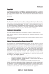
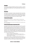
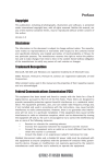
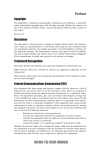
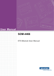
57
If fail, contact RMA
CLR CMOS and restart.
Yes
Halt at POST screen
Yes
Check if monitor has
display
Yes
Check if Power Supply
Unit (PSU) is working
Power Bu on is pressed
but PC fails to start.
-
need to CLRCMOS.
HDD problem.
CMOS setup error,
-
Peripheral device issue
No
No
No
VGA not detected
- If 1 long beep and 8 short beeps:
inserted or memory failure
DIMM memory not properly
- If 3 short beeps:
Yes
Any Beep sound
No
Yes
Check if monitor
has display
Restart the PC
is connected
if CPU 12V power
CLR CMOS and check
Basic Troubleshooting Flowchart
Problem with PSU or board?
Yes
-> contact RMA
Board problem
If board problem -> contact RMA
a er modify BIOS se ng.
System fail to start or unstable
No
AC power cord is plugged
and PSU switch is turned on?
CLR CMOS and restart
and restart.
or connect to wall socket
Turn on PSU switch
No
Memo
Chapter 5
58
NM70-TI USER MANUAL