1
Cat. No. W485-E1-02
3G8F7-CRM21 (for PCI Bus)
3G8F8-CRM21 (for CompactPCI Bus)
CompoNet Master Board
for PCI Bus / CompactPCI Bus
TM
USER’S MANUAL
Trademarks and Copyrights
Microsoft, Windows, Windows 2000, Windows XP, Windows Vista, Windows 7, Visual Basic, and
Visual C++ are registered trademarks of the Microsoft Corporation.
C++Builder is the registered trademark of the Embarcadero Technologies, Inc.
ODVA, CIP, CompoNet, DeviceNet, and EtherNet/IP are trademarks of the Open DeviceNet Vendor
Association, Inc.
Other product names and company names in this manual are trademarks or registered trademarks of
their respective companies.
The copyright of the CompoNet Master Boards for PCI Bus and for CompactPCI Bus, and related
software belongs to OMRON Corporation.
3G8F7-CRM21 (for PCI Bus)
3G8F8-CRM21 (for CompactPCI Bus)
CompoNet
TM
Master Board for PCI Bus / CompactPCI Bus
User’s Manual
Revised September 2013
iv
Notice:
OMRON products are manufactured for use according to proper procedures by a qualified operator
and only for the purposes described in this manual.
The following conventions are used to indicate and classify precautions in this manual. Always heed
the information provided with them. Failure to heed precautions can result in injury to people or
damage to property.
DANGER
Indicates an imminently hazardous situation which, if not avoided, will result in death or
serious injury. Additionally, there may be severe property damage.
WARNING
Indicates a potentially hazardous situation which, if not avoided, could result in death or
serious injury. Additionally, there may be severe property damage.
Caution
Indicates a potentially hazardous situation which, if not avoided, may result in minor or
moderate injury, or property damage.
OMRON Product References
All OMRON products are capitalized in this manual. The word "Unit" is also capitalized when it refers to
an OMRON product, regardless of whether or not it appears in the proper name of the product.
The abbreviation "Ch," which appears in some parts of this manual and on some displays and on
OMRON products, has two meanings which must be distinguished in context. In one case, it means
"word" as an aggregation of data, and is abbreviated "Wd". In other case, it refers to a physical input or
output channel. In latter case, when a model has two input channels, they are referred to as Input 1
and Input 2.
The abbreviation "PC" refers to personal computers while "PLC" means Programmable Controller.
Visual Aids
The following headings appear in the left column of the manual to help you locate different types of
information.
Precautions for Safe Use
Supplementary comments on what to do or avoid doing, to use the product
safely
Precautions for Correct Use
Supplementary comments on what to do or avoid doing, to prevent failure to
operate, or undesirable effect on product performance
Note Notes in the document refer to equivalent content to the Precautions for
Correct Use or to Precautions for Safe Use.
It also indicates information of particular interest for efficient and convenient
operation of the product.
1,2,3...
1. Indicates lists of one sort or another, such as procedures, checklists, etc.
v
OMRON, 2009
All rights reserved. No part of this publication may be reproduced, stored in a retrieval system, or transmitted, in any form, or
by any means, mechanical, electronic, photocopying, recording, or otherwise, without the prior written permission of
OMRON.
No patent liability is assumed with respect to the use of the information contained herein. Moreover, because OMRON is
constantly striving to improve its high-quality products, the information contained in this manual is subject to change without
notice. Every precaution has been taken in the preparation of this manual. Nevertheless, OMRON assumes no responsibility
for errors or omissions. Neither is any liability assumed for damages resulting from the use of the information contained in
this publication.
vi
TABLE OF CONTENTS
PRECAUTIONS. . . . . . . . . . . . . . . . . . . . . . . . . . . . . . . . . . .
xv
1
Intended Audience . . . . . . . . . . . . . . . . . . . . . . . . . . . . . . . . . . . . . . . . . . . . . . . . . . . . . . . .
xvi
2
General Precautions . . . . . . . . . . . . . . . . . . . . . . . . . . . . . . . . . . . . . . . . . . . . . . . . . . . . . . .
xvi
3
Safety Precautions . . . . . . . . . . . . . . . . . . . . . . . . . . . . . . . . . . . . . . . . . . . . . . . . . . . . . . . .
xvii
4
Operating Environment Precautions. . . . . . . . . . . . . . . . . . . . . . . . . . . . . . . . . . . . . . . . . . .
xvii
5
Application Precautions . . . . . . . . . . . . . . . . . . . . . . . . . . . . . . . . . . . . . . . . . . . . . . . . . . . .
xvii
6
Conformance with the EC Directives . . . . . . . . . . . . . . . . . . . . . . . . . . . . . . . . . . . . . . . . . .
xx
SECTION 1
Outline of CompoNet and CompoNet Master Board . . . . .
1
1-1
Overview of the CompoNet Network. . . . . . . . . . . . . . . . . . . . . . . . . . . . . . . . . . . . . . . . . .
2
1-2
Overview of the CompoNet Master Board. . . . . . . . . . . . . . . . . . . . . . . . . . . . . . . . . . . . . .
3
1-3
Component Name and Function. . . . . . . . . . . . . . . . . . . . . . . . . . . . . . . . . . . . . . . . . . . . . .
4
1-4
LED Indication . . . . . . . . . . . . . . . . . . . . . . . . . . . . . . . . . . . . . . . . . . . . . . . . . . . . . . . . . . .
6
1-5
Network Construction Procedure . . . . . . . . . . . . . . . . . . . . . . . . . . . . . . . . . . . . . . . . . . . . .
7
1-6
Board Preparation Procedure . . . . . . . . . . . . . . . . . . . . . . . . . . . . . . . . . . . . . . . . . . . . . . . .
8
1-7
Specifications . . . . . . . . . . . . . . . . . . . . . . . . . . . . . . . . . . . . . . . . . . . . . . . . . . . . . . . . . . . .
9
SECTION 2
Installation and Setup . . . . . . . . . . . . . . . . . . . . . . . . . . . . . .
11
2-1
Mounting a Board. . . . . . . . . . . . . . . . . . . . . . . . . . . . . . . . . . . . . . . . . . . . . . . . . . . . . . . . .
12
2-2
Installing the Drivers . . . . . . . . . . . . . . . . . . . . . . . . . . . . . . . . . . . . . . . . . . . . . . . . . . . . . .
14
2-3
Connecting the Communications Cables . . . . . . . . . . . . . . . . . . . . . . . . . . . . . . . . . . . . . . .
21
2-4
Connecting the Communications Power Supply Cables . . . . . . . . . . . . . . . . . . . . . . . . . . .
25
SECTION 3
Functions . . . . . . . . . . . . . . . . . . . . . . . . . . . . . . . . . . . . . . . . .
27
3-1
Settings at Communications Cycle Startup . . . . . . . . . . . . . . . . . . . . . . . . . . . . . . . . . . . . .
28
3-2
Access to I/O Data . . . . . . . . . . . . . . . . . . . . . . . . . . . . . . . . . . . . . . . . . . . . . . . . . . . . . . . .
30
3-3
Status . . . . . . . . . . . . . . . . . . . . . . . . . . . . . . . . . . . . . . . . . . . . . . . . . . . . . . . . . . . . . . . . . .
35
3-4
Explicit Messages. . . . . . . . . . . . . . . . . . . . . . . . . . . . . . . . . . . . . . . . . . . . . . . . . . . . . . . . .
37
3-5
Detailed Settings at Communications Cycle Startup . . . . . . . . . . . . . . . . . . . . . . . . . . . . . .
37
SECTION 4
Operation by API Functions . . . . . . . . . . . . . . . . . . . . . . . . .
41
4-1
Access to I/O Data . . . . . . . . . . . . . . . . . . . . . . . . . . . . . . . . . . . . . . . . . . . . . . . . . . . . . . . .
42
4-2
Detailed Setting at Communications Cycle Startup . . . . . . . . . . . . . . . . . . . . . . . . . . . . . . .
45
4-3
Explicit Messaging . . . . . . . . . . . . . . . . . . . . . . . . . . . . . . . . . . . . . . . . . . . . . . . . . . . . . . . .
46
4-4
Setting the Time Information . . . . . . . . . . . . . . . . . . . . . . . . . . . . . . . . . . . . . . . . . . . . . . . .
48
4-5
Implementing the Reset Request . . . . . . . . . . . . . . . . . . . . . . . . . . . . . . . . . . . . . . . . . . . . .
49
vii
TABLE OF CONTENTS
4-6
Access to Detailed Status Group . . . . . . . . . . . . . . . . . . . . . . . . . . . . . . . . . . . . . . . . . . . . . .
50
4-7
PC Watchdog Timer. . . . . . . . . . . . . . . . . . . . . . . . . . . . . . . . . . . . . . . . . . . . . . . . . . . . . . . .
52
4-8
Board Hardware Error Notification . . . . . . . . . . . . . . . . . . . . . . . . . . . . . . . . . . . . . . . . . . . .
53
SECTION 5
Operation by Accessing to Shared Memory. . . . . . . . . . . . .
55
5-1
Basic Procedures . . . . . . . . . . . . . . . . . . . . . . . . . . . . . . . . . . . . . . . . . . . . . . . . . . . . . . . . . .
56
5-2
Communications Cycle Control Procedures . . . . . . . . . . . . . . . . . . . . . . . . . . . . . . . . . . . . .
58
5-3
Setting the Time Information. . . . . . . . . . . . . . . . . . . . . . . . . . . . . . . . . . . . . . . . . . . . . . . . .
63
5-4
Implementing the Reset Request . . . . . . . . . . . . . . . . . . . . . . . . . . . . . . . . . . . . . . . . . . . . . .
63
5-5
PC Watchdog Timer. . . . . . . . . . . . . . . . . . . . . . . . . . . . . . . . . . . . . . . . . . . . . . . . . . . . . . . .
64
5-6
Board Hardware Error Notification . . . . . . . . . . . . . . . . . . . . . . . . . . . . . . . . . . . . . . . . . . . .
65
SECTION 6
Troubleshooting . . . . . . . . . . . . . . . . . . . . . . . . . . . . . . . . . . .
67
6-1
LED Indications and Error Handling. . . . . . . . . . . . . . . . . . . . . . . . . . . . . . . . . . . . . . . . . . .
68
6-2
Error Log . . . . . . . . . . . . . . . . . . . . . . . . . . . . . . . . . . . . . . . . . . . . . . . . . . . . . . . . . . . . . . . .
70
APPENDIX A
API Function Reference . . . . . . . . . . . . . . . . . . . . . . . . . . . . .
73
A-1 Function List . . . . . . . . . . . . . . . . . . . . . . . . . . . . . . . . . . . . . . . . . . . . . . . . . . . . . . . . . . . . .
74
A-2 Board Control API. . . . . . . . . . . . . . . . . . . . . . . . . . . . . . . . . . . . . . . . . . . . . . . . . . . . . . . . .
76
A-3 Communications Control API . . . . . . . . . . . . . . . . . . . . . . . . . . . . . . . . . . . . . . . . . . . . . . . .
77
A-4 Status Access API . . . . . . . . . . . . . . . . . . . . . . . . . . . . . . . . . . . . . . . . . . . . . . . . . . . . . . . . .
85
A-5 I/O Data Access API . . . . . . . . . . . . . . . . . . . . . . . . . . . . . . . . . . . . . . . . . . . . . . . . . . . . . . .
90
A-6 Explicit Messaging API. . . . . . . . . . . . . . . . . . . . . . . . . . . . . . . . . . . . . . . . . . . . . . . . . . . . .
93
A-7 PC Watchdog Timer API . . . . . . . . . . . . . . . . . . . . . . . . . . . . . . . . . . . . . . . . . . . . . . . . . . . .
97
A-8 Board Request Notification API . . . . . . . . . . . . . . . . . . . . . . . . . . . . . . . . . . . . . . . . . . . . . .
98
A-9 Errors Detectable by Functions . . . . . . . . . . . . . . . . . . . . . . . . . . . . . . . . . . . . . . . . . . . . . . .
100
APPENDIX B
Shared Memory Interface . . . . . . . . . . . . . . . . . . . . . . . . . . . 101
B-1
PCI Resources . . . . . . . . . . . . . . . . . . . . . . . . . . . . . . . . . . . . . . . . . . . . . . . . . . . . . . . . . . . .
102
B-2
PCI Register Specifications . . . . . . . . . . . . . . . . . . . . . . . . . . . . . . . . . . . . . . . . . . . . . . . . . .
103
B-3
Shared Memory Area Specifications . . . . . . . . . . . . . . . . . . . . . . . . . . . . . . . . . . . . . . . . . . .
107
B-4
Command Specifications . . . . . . . . . . . . . . . . . . . . . . . . . . . . . . . . . . . . . . . . . . . . . . . . . . . .
142
APPENDIX C
Communications Performance . . . . . . . . . . . . . . . . . . . . . . . 147
C-1
viii
Remote I/O Communications Performance. . . . . . . . . . . . . . . . . . . . . . . . . . . . . . . . . . . . . .
148
TABLE OF CONTENTS
APPENDIX D
Sample Program . . . . . . . . . . . . . . . . . . . . . . . . . . . . . . . . . . . 153
D-1 Sample Program. . . . . . . . . . . . . . . . . . . . . . . . . . . . . . . . . . . . . . . . . . . . . . . . . . . . . . . . . . .
154
APPENDIX E
Installation and Setup. . . . . . . . . . . . . . . . . . . . . . . . . . . . . . . 155
E-1
CompoNet Network Specifications . . . . . . . . . . . . . . . . . . . . . . . . . . . . . . . . . . . . . . . . . . . .
156
E-2
Wiring Formations . . . . . . . . . . . . . . . . . . . . . . . . . . . . . . . . . . . . . . . . . . . . . . . . . . . . . . . . .
165
E-3
Wiring for a CompoNet Network . . . . . . . . . . . . . . . . . . . . . . . . . . . . . . . . . . . . . . . . . . . . .
167
E-4
Preparing and Mounting Flat Connectors on the Cables . . . . . . . . . . . . . . . . . . . . . . . . . . . .
180
E-5
Wiring for Power Supply . . . . . . . . . . . . . . . . . . . . . . . . . . . . . . . . . . . . . . . . . . . . . . . . . . . .
195
ix
TABLE OF CONTENTS
x
About This Manual
This manual describes the installation and operation of the 3G8F7-CRM21 CompoNet Master Board
for PCI Bus and the 3G8F8-CRM21 CompoNet Master Board for CompactPCI Bus. The CompoNet
Master Board functions as the CompoNet Master Unit. There are two types: One is compatible with
PCI bus (model # 3G8F7-CRM21), and the other is compatible with CompactPCI bus (model # 3G8F8CRM21) .
Please read this manual carefully and be sure you understand the information provided before
attempting to install or operate a CompoNet Master Board. Be sure to read the precautions provided in
the following section. Also be sure to read the CompoNet Slave Unit Operation Manual (see following
table) together with this manual.
The manual contains the following sections:
Precautions provide general precautions for using the CompoNet Master Board and related devices.
Section 1 outlines the CompoNet and the CompoNet Master Board. Read this section carefully before
you use the CompoNet Master Board for the first time.
Section 2 outlines the installation and setup. It includes procedures to mount a Board, to install a
driver, and to connect the communications cables.
Section 3 describes the functions of the CompoNet Master Boards. There are basic and special
functions.
Section 4 describes the operations by API functions to control the Board in the Windows operation
systems.
Section 5 describes the operations by shared memory access to control the Board in operation
systems, other than Windows.
Section 6 describes the troubleshooting. It is recommended to read them first to prevent any errors
from occurring.
Appendix A describes the API functions.
Appendix B describes the shared memory interfaces.
Appendix C explains the communications performance.
Appendix D describes the sample program provided in the product package.
Appendix E describes the construction of a CompoNet Network.
It includes the network specifications, the wiring procedures and the preparation of Flat Connectors.
xi
Related Manuals
Cat No.
W485
(this manual)
Model
3G8F7-CRM21
3G8F8-CRM21
W457
CRT1
W456
CS1W-CRM21
CJ1WCRM21
WARNING
xii
Name
Description
CompoNet Master Board for Provides the specifications of
PCI Bus and for CompactPCI the CompoNet Master Board
Bus Operation Manual
Provides the specifications of
CR1-series CompoNet TM
Slave Units and Repeater Unit CompoNet Slave Units and
Repeater Units
Operation Manual
TM
CS/CJ-series CompoNet TM
Master Units Operation
Manual
Provides an overview of
CompoNet Networks,
communications
specifications, wiring
methods, and CompoNet
Master Unit functions
The failure to read and understand the information provided in this manual may result in
personal injury or death, damage to the product or product failure. Please read each
section in its entirety, and be sure you understand the information provided in the section
and related sections before attempting any of the procedures or operations.
Terms and Conditions Agreement
Read and understand this Manual
Please read and understand this catalog before purchasing the products. Please consult your
OMRON representative if you have any questions or comments.
Warranty, Limitations of Liability
Warranties
z Exclusive Warranty
Omron’s exclusive warranty is that the Products will be free from defects in materials and workmanship for a period of twelve months from the date of sale by Omron (or such other period
expressed in writing by Omron). Omron disclaims all other warranties, express or implied.
z Limitations
OMRON MAKES NO WARRANTY OR REPRESENTATION, EXPRESS OR IMPLIED, ABOUT
NON-INFRINGEMENT, MERCHANTABILITY OR FITNESS FOR A PARTICULAR PURPOSE OF
THE PRODUCTS. BUYER ACKNOWLEDGES THAT IT ALONE HAS DETERMINED THAT THE
PRODUCTS WILL SUITABLY MEET THE REQUIREMENTS OF THEIR INTENDED USE.
Omron further disclaims all warranties and responsibility of any type for claims or expenses based
on infringement by the Products or otherwise of any intellectual property right.
z Buyer Remedy
Omron’s sole obligation hereunder shall be, at Omron’s election, to (i) replace (in the form originally shipped with Buyer responsible for labor charges for removal or replacement thereof) the
non-complying Product, (ii) repair the non-complying Product, or (iii) repay or credit Buyer an
amount equal to the purchase price of the non-complying Product; provided that in no event shall
Omron be responsible for warranty, repair, indemnity or any other claims or expenses regarding
the Products unless Omron’s analysis confirms that the Products were properly handled, stored,
installed and maintained and not subject to contamination, abuse, misuse or inappropriate modification. Return of any Products by Buyer must be approved in writing by Omron before shipment.
Omron Companies shall not be liable for the suitability or unsuitability or the results from the use
of Products in combination with any electrical or electronic components, circuits, system assemblies or any other materials or substances or environments. Any advice, recommendations or
information given orally or in writing, are not to be construed as an amendment or addition to the
above warranty.
See http://www.omron.com/global/ or contact your Omron representative for published information.
Limitation on Liability; Etc
OMRON COMPANIES SHALL NOT BE LIABLE FOR SPECIAL, INDIRECT, INCIDENTAL, OR CONSEQUENTIAL DAMAGES, LOSS OF PROFITS OR PRODUCTION OR COMMERCIAL LOSS IN
ANY WAY CONNECTED WITH THE PRODUCTS, WHETHER SUCH CLAIM IS BASED IN CONTRACT, WARRANTY, NEGLIGENCE OR STRICT LIABILITY.
Further, in no event shall liability of Omron Companies exceed the individual price of the Product on
which liability is asserted.
xiii
Application Considerations
Suitability of Use
Omron Companies shall not be responsible for conformity with any standards, codes or regulations
which apply to the combination of the Product in the Buyer’s application or use of the Product. At
Buyer’s request, Omron will provide applicable third party certification documents identifying ratings
and limitations of use which apply to the Product. This information by itself is not sufficient for a complete determination of the suitability of the Product in combination with the end product, machine,
system, or other application or use. Buyer shall be solely responsible for determining appropriateness of the particular Product with respect to Buyer’s application, product or system. Buyer shall take
application responsibility in all cases.
NEVER USE THE PRODUCT FOR AN APPLICATION INVOLVING SERIOUS RISK TO LIFE OR
PROPERTY WITHOUT ENSURING THAT THE SYSTEM AS A WHOLE HAS BEEN DESIGNED TO
ADDRESS THE RISKS, AND THAT THE OMRON PRODUCT(S) IS PROPERLY RATED AND
INSTALLED FOR THE INTENDED USE WITHIN THE OVERALL EQUIPMENT OR SYSTEM.
Programmable Products
Omron Companies shall not be responsible for the user’s programming of a programmable Product,
or any consequence thereof.
Disclaimers
Performance Data
Data presented in Omron Company websites, catalogs and other materials is provided as a guide for
the user in determining suitability and does not constitute a warranty. It may represent the result of
Omron’s test conditions, and the user must correlate it to actual application requirements. Actual performance is subject to the Omron’s Warranty and Limitations of Liability.
Change in Specifications
Product specifications and accessories may be changed at any time based on improvements and
other reasons. It is our practice to change part numbers when published ratings or features are
changed, or when significant construction changes are made. However, some specifications of the
Product may be changed without any notice. When in doubt, special part numbers may be assigned
to fix or establish key specifications for your application. Please consult with your Omron’s representative at any time to confirm actual specifications of purchased Product.
Errors and Omissions
Information presented by Omron Companies has been checked and is believed to be accurate; however, no responsibility is assumed for clerical, typographical or proofreading errors or omissions.
xiv
PRECAUTIONS
This section provides general precautions for use of the CompoNet Master Boards.
The information contained in this section is important for the safe, reliable application of the CompoNet Master
Board. You must read this section and understand the information contained before attempting to set up or
operate a CompoNet Network using CompoNet Master Boards.
1
Intended Audience . . . . . . . . . . . . . . . . . . . . . . . . . . . . . . . . . . . . . . . . . . . . .
xvi
2
General Precautions . . . . . . . . . . . . . . . . . . . . . . . . . . . . . . . . . . . . . . . . . . . .
xvi
3
Safety Precautions . . . . . . . . . . . . . . . . . . . . . . . . . . . . . . . . . . . . . . . . . . . . .
xvii
4
Operating Environment Precautions. . . . . . . . . . . . . . . . . . . . . . . . . . . . . . . .
xvii
5
Application Precautions . . . . . . . . . . . . . . . . . . . . . . . . . . . . . . . . . . . . . . . . .
xvii
6
Conformance with the EC Directives. . . . . . . . . . . . . . . . . . . . . . . . . . . . . . .
xx
6-1
Applicable Directives. . . . . . . . . . . . . . . . . . . . . . . . . . . . . . . . . . . .
xx
6-2
Concepts. . . . . . . . . . . . . . . . . . . . . . . . . . . . . . . . . . . . . . . . . . . . . .
xx
6-3
Conformity . . . . . . . . . . . . . . . . . . . . . . . . . . . . . . . . . . . . . . . . . . . .
xx
xv
1
Intended Audience
1
Intended Audience
This manual is intended for the following personnel to read and use. The
personnel must have knowledge of electrical systems and would therefore be
electrical engineers or the equivalent:
• Personnel in charge of introducing FA systems
• Personnel in charge of designing FA systems
• Personnel in charge of managing FA systems and facilities
2
General Precautions
The user must operate the product according to the performance
specifications described in the operation manuals. Before using the product
under conditions that are not described in the manual or when applying the
product to nuclear control systems, railroad systems, aviation systems,
vehicles, combustion systems, medical equipment, amusement machines or
safety equipment, or to other systems, machines and equipment that may
have a serious influence on lives and property if used improperly, consult your
OMRON representative.
Be certain the ratings and performance characteristics of the product are
sufficient for the systems, machines and equipment, and be sure to provide
the systems, machines and equipment with double safety mechanisms.
This manual provides information for programming and operating the Unit. Be
sure to read this manual before attempting to use the Unit, and keep this
manual close at hand for reference during operation.
Be sure this manual is delivered to the persons actually using the CompoNet
Master Boards.
WARNING
xvi
It is extremely important that a PLC and all PLC Units be used for the specified purpose
and under the specified conditions, especially in applications that can directly or indirectly
affect human life. You must consult with your OMRON representative before applying a
PLC System to the above-mentioned applications.
3
Safety Precautions
3
4
Safety Precautions
WARNING
Do not attempt to take any Unit apart or touch the component inside while the power is
being supplied. Doing so may result in electric shock.
WARNING
Do not touch any of the terminals or terminal blocks while the power is being supplied.
Doing so may result in electric shock.
WARNING
Fail-safe measures must be taken by the user to ensure safety in the event of incorrect,
missing or abnormal signals caused by broken signal lines, momentary power
interruptions or other causes. Serious accidents may result from abnormal operation if
proper measures are not provided.
WARNING
Provide safety measures in external circuits (i.e., not in the personal computers) that
ensure safety of the system in any event of an abnormality due to malfunction of the PC
or another external factor affecting the PC operation. The failure to do so may result in
serious accidents. Emergency stop circuits, interlock circuits, limit circuits and similar
safety measures must be provided in external control circuits.
Caution
Confirm safety at the destination Slave Unit before changing it or transferring parameters
to another node. Changing or transferring any of these without confirming safety may
result in unexpected equipment operation.
Caution
A Slave Unit may change the output content if it faces a communications failure. When
you use outputting devices, confirm their operation specification on an event of
communications failure, and take the necessary safety measures.
Operating Environment Precautions
Caution
Do not operate the products in the following locations.
• Locations subject to direct sunlight
• Locations subject to temperatures or humidity outside the range
specified in the specifications
• Locations subject to condensation as the result of severe changes in
temperature
• Locations subject to corrosive or flammable gases
• Locations subject to dust (especially iron dust) or salts
• Locations subject to exposure to water, oil, or chemicals (including
acids)
• Locations subject to shock or vibration
5
Application Precautions
Observe the following precautions when using a CompoNet Network.
• When more than one CompoNet system use Flat Cables, always
separate the Flat Cables from each other by at least 5 mm regardless of
whether Flat Cable I or II is used. Do not bundle the Flat Cables. This is to
prevent unstable operation of the system due to interference.
xvii
5
Application Precautions
• Fail-safe measures must be taken by the customer to ensure safety in the
event of incorrect, missing or abnormal signals caused by broken signal
lines, momentary power interruptions or other causes.
• Configure the control circuits so that the power to the PC (near the
CompoNet Master Board) will be on after the power to the I/O Slave Units.
If the PC power supply is turned on first, normal operation will not be
ensured, even temporarily.
• Use the Boards within the communications distance and the number of
connectable Units as defined in the specifications.
• Do not attempt to disassemble, repair or modify any Units. Any attempt to
do so may result in a malfunction, fire or electric shock.
• When installing the Unit, ground to 100 Ω/min.
• Be certain all screws to fix the Board to the PC, as well as the screws on
connectors, cables and terminal blocks, are tightened to the torque
specified in the corresponding manuals. Incorrect tightening torque may
result in a malfunction.
• Be sure the Board on the PC is securely mounted.
• All installation and wiring must observe the instructions in this manual.
• Use correct wiring tools and components for wiring.
• Confirm the orientation and polarity before connecting the terminal blocks
or connectors.
• Do not supply electricity while a terminal block cover is open.
• Confirm voltage specifications before wiring the communications lines,
the power supplies or the I/O circuits. Incorrect specification may result in
a malfunction.
• Install external breakers and take other safety measures against shortcircuiting in the external wiring. Insufficient safety measures against
short-circuiting may result in burning.
• Use crimp terminals for wiring. Do not connect bare stranded wires
directly to terminals. The connection of bare stranded wires may result in
burning.
• Double-check all wiring and switch settings before turning ON the power
supply. Incorrect wiring may result in burning.
• Be sure no waste metal enters the PC during the installation and wiring
work.
• Be certain the terminal blocks, connectors, expansion cables,
communications cables and other items with locking devices are properly
locked in place. Improper locking may result in a malfunction.
• Always use the power-supply voltages specified in the operation manual.
A malfunction or burning may occur as the result of incorrect voltage.
• Take appropriate measures to ensure that the specified power with the
rated voltage and frequency is supplied. Be particularly careful in places
where the power supply is unstable. An incorrect power supply may result
in a malfunction.
• Check the user program for proper execution before actually running it on
the Unit. The failure to check the program may result in unexpected
operation.
• Always turn OFF the power supply to the personal computer, the Slave
Units and communications before attempting any of the following. The
failure to turn OFF the power supply may result in a malfunction or electric
shock.
xviii
5
Application Precautions
• Mounting or removing a CompoNet Master Board
• Assembling devices
• Setting rotary switches
• Connecting cables or wiring the system
• Connecting or disconnecting the connectors
• Close the PC cover before wiring work. This is used to prevent wire waste
from entering the PC.
• Before touching a CompoNet Master Board, be sure to first touch a
grounded metallic object in order to discharge any static buildup. The
failure to do so may result in a malfunction or damage.
• When replacing parts, be sure to confirm that the rating of the new part is
correct. The failure to do so may result in a malfunction or burning.
• When transporting a CompoNet Master Board, use special packing boxes
and protect it from exposure to excessive vibration or impact during
transportation.
• Use the Board in the specified ambient operating temperature and
humidity.
• Store the Board in the specified ambient storage temperature.
• Circuit boards have sharp edges such as leads of electric components.
Do not touch the parts where such components are mounted or the backs
of circuit boards by hand.
• Use only the specified communications cables.
• Do not extend connection distances beyond the ranges given in the
specifications.
• Observe the given precautions when wiring the communications cable.
• Separate the communications cables from the power lines or high-tension
lines.
• Do not bend the communications cables past their natural bending radius.
• Do not pull on the communications cables.
• Do not place heavy objects atop the communications cables.
• Always lay communications cables inside ducts.
• Take appropriate and sufficient countermeasures when installing systems
in the following locations:
• Locations subject to static electricity or other forms of noise
• Locations subject to strong electromagnetic fields
• Locations subject to possible exposure to radioactivity
• Locations close to power supplies
• Do not use the computer’s standby or sleep function while you are using
the CompoNet Master Board. If the computer’s standby or sleep function
is activated during CompoNet Master Board usage, communications may
be broken or other unexpected errors may occur.
• The CompoNet Master Board does not support computer standby or
sleep functions. Do not use the computer’s standby or sleep function
while you are using the CompoNet Master Board.
xix
Conformance with the EC Directives
6
6-1
6
Conformance with the EC Directives
Applicable Directives
• EMC Directives
6-2
Concepts
EMC Directives
The OMRON products are electric components that usually are used after
being built in other machinery or manufacturing equipment. They are
designed to conform to the relevant EMC Directives. This will facilitate the
compliance of the final machinery or apparatus to such directives. However,
the installation and configuration of such machinery and apparatus in which
the OMRON products are mounted and used will differ according to their
characteristics. Thus it is virtually impossible for OMRON to ensure the
conformity of an entire system to the relevant EMC Directives. The users must
conduct the necessary tests and ensure the conformity of the system as a
whole.
The relevant EMC Directives are:
EN 61131-2 and EN 61000-6-2 for EMS, i.e., Electromagnetic susceptibility,
EN 61131-2 and EN 61000-6-4 for EMI, i.e., Electromagnetic Interference,
and EN61000-6-4 for Radiated emission, 10-m regulations, among EMC
(Electro-Magnetic Compatibility).
6-3
Conformity
The OMRON products in this manual comply with the relevant EMC
Directives. To ensure that the machinery or apparatus in which the OMRON
products are used complies with the EC Directives, the user must follow these
instructions:
1,2,3...
1. The OMRON product must be installed in a control panel.
2. DC power supply unit as well as DC power connected to I/O Units must
have reinforced insulation or double insulation.
3. Compliance to the EC Directives means conformity to the Emission
Standards (EN 61000-6-4). Radiated emission characteristics (10-m
regulations) may vary, however, depending on the configuration of the
control panel used, the compatibility with other devices connected to the
control panel, the effects of wiring and other conditions. The user must
confirm that the overall machine or equipment complies with the EC
Directives.
xx
SECTION 1
Outline of CompoNet and CompoNet Master Board
1-1
Overview of the CompoNet Network . . . . . . . . . . . . . . . . . . . . . . . . . . . . . . .
2
1-2
Overview of the CompoNet Master Board . . . . . . . . . . . . . . . . . . . . . . . . . . .
3
1-3
Component Name and Function . . . . . . . . . . . . . . . . . . . . . . . . . . . . . . . . . . .
4
1-3-1
3G8F7-CRM21 (for PCI Bus). . . . . . . . . . . . . . . . . . . . . . . . . . . . . .
4
1-3-2
3G8F8-CRM21 (for CompactPCI Bus) . . . . . . . . . . . . . . . . . . . . . .
5
1-4
LED Indication . . . . . . . . . . . . . . . . . . . . . . . . . . . . . . . . . . . . . . . . . . . . . . . .
6
1-5
Network Construction Procedure . . . . . . . . . . . . . . . . . . . . . . . . . . . . . . . . . .
7
1-6
Board Preparation Procedure. . . . . . . . . . . . . . . . . . . . . . . . . . . . . . . . . . . . . .
8
1-7
Specifications. . . . . . . . . . . . . . . . . . . . . . . . . . . . . . . . . . . . . . . . . . . . . . . . . .
9
1-7-1
General Specifications. . . . . . . . . . . . . . . . . . . . . . . . . . . . . . . . . . . .
9
1-7-2
Development Environment . . . . . . . . . . . . . . . . . . . . . . . . . . . . . . . .
9
1-7-3
Dimensions . . . . . . . . . . . . . . . . . . . . . . . . . . . . . . . . . . . . . . . . . . . .
10
1
Section 1-1
Overview of the CompoNet Network
1-1
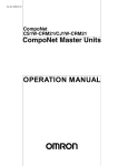
Overview of the CompoNet Network
CompoNet is a field network designed for communications between the input
and output components on the shop floor and a personal computer (or PC) or
a PLC. CompoNet requires less wiring labor but provides high maintainability.
The PC and the CompoNet Slave Unit exchange input and/or output data
cyclically through a CompoNet Master Board.
By using explicit messages, users can read data from the CompoNet Slave
Unit or write data into it.
CompoNet Master Board
Slave Unit
Terminating Resistor
Repeater
Unit
Terminating
Resistor
Repeater Unit
Terminating
Resistor
Slave Unit
Slave Unit
Slave Unit
Here are the main features of CompoNet:
High-Speed
Communications of
Multiple Nodes
CompoNet can provide remote I/O communications for multiple nodes as
many as maximum 2,560 points in a high speed such as 1000 points per
millisecond when the data rate is 4 Mbps*. This allows integration of
conventional system configuration with basic I/O Units into a CompoNet
network.
*
Greater Flexibility with
Repeater Units
The data rate of 4 Mbps does not support T-branch connection. Thus any
Slave Unit with pre-attached cables is not usable.
Repeater Units can expand a network installation in the following ways:
• Extending the Communications cable,
• Increasing the number of connected nodes,
• Creating a branch connection from the trunk line, and
• Converting cable types.
Repeater Units can be used to expand the trunk line for up to two layers. The
lines downstream from the Repeater Units are called sub-trunk lines. The
maximum number of connectable Repeater Units is 64 per Master Board and
32 per trunk line.
Note
2
The power to the sub-trunk lines must be supplied from the Repeater Units.
Overview of the CompoNet Master Board
Section 1-2
Bit-Level Distribution
CompoNet is connectable with industry-standard e-CON connectors and
Slave Units of clamp terminal-block type. They allow bit-level controls of
conveyors or at warehouses where many sensors are placed over a wide
range.
Data Exchange by Explicit
Messages
Explicit messages are used to access from the PC to the Slave Units and
Repeater Units connected to the CompoNet network. This feature facilitates
the maintenance of the entire network.
Automatic Baud Rate
Detection
By setting the baud rate on the CompoNet Master Board, the Slave Units
automatically detect the baud rate of the CompoNet Master Board and follow
it. There is no need to set the rate individually on the Slave Units.
1-2
Overview of the CompoNet Master Board
CompoNet Master Board is a board that has a mastering function to control
inputs and outputs for the Slave Units connected to the CompoNet network.
The Board is either compatible with PCI bus (Model # 3G8F7-CRM21) or with
CompactPCI bus (Model # 3G8F8-CRM21).
Here are the main features of the CompoNet Master Board:
Control by API Functions
In the Windows operation systems, all functions on the CompoNet Master
Board can be accessed by API functions.
Control by Shared
memory Accesses
In operation systems other than Windows, the CompoNet Master Board is
used via access to shared memory.
Flexible Allocation of the
Number of Connectable
Nodes
The number of connectable nodes can be set differently for each Word Input
Slave Units, Word Output Slave Units, Bit Input Slave Units and Bit Output
Slave Units.
Registration Table
Function to Control
Participating Slave Units
This function is used to pre-register the node addresses and models of Slave
Units that are to participate in the network, and to check whether a Slave Unit
that is actually participating is registered or not. If the Slave Unit is not
registered, it is not allowed to participate. The time can also be set to monitor
duration from power-on until a registered Slave Unit actually participates.
Remote I/O communications can be stopped until all registered Slave Units
participate in the network, but it can be started only with all Slave Units
participating. The latter function is called the All Registered Slave
Participation Standby Mode.
Optimizing
Communications Cycle
When the Registration Table function is used, the communications cycle is
optimized and fastened in accordance with the information in the table.
Synchronous and
Asynchronous Access to
I/O Data
Both synchronous and asynchronous types of access are supported.
Synchronous access maintains synchronicity for each node, while
asynchronous access does not do that but instead provides faster access. In
the latter case, I/O data keeps synchronicity only within the same word.
Other Functions
• Communications Stop Due to Communications Error function
• I/O Communications Manual Startup mode
• IN Data Zero Clear Due to Communications Error function
3
Section 1-3
Component Name and Function
1-3
1-3-1
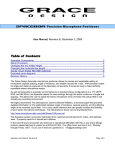
Component Name and Function
3G8F7-CRM21 (for PCI Bus)
Board ID Switch
LED Indicators (MS and NS)
They indicate the Module Status (MS)
and Network Status (NS) that are
defined in the CompoNet protocol.
This is used to set the board ID. It is set as a
decimal number. The number must not
overlap the IDs for other CompoNet Master
Boards mounted on the same personal
computer.
Communications power supply connector
This is used to connect a 24-VDC power supply when either
round cable II or Flat Cable I or II is used.
The communications power is supplied through this connector
and the round cable II, Flat Cable I or Flat Cable II to the Slave
Units and Repeater Units on the trunk line.
Note : Do not connect anything to this connector when a round
cable I is used.
Communications connector
This is used to connect to the communications cable.
The terminals BS+ and BS- are for communications power supply. The terminals BDH and BDL are for
communications data.
The BS+ and BS- can be used only for round cable II or Flat Cable I or II. They output the
communications power from the power supply connected to the communications power supply
connector.
Note : By attaching an Open Type Connector for Unit connection, the communications connector can be
converted to a terminal-block type.
4
Section 1-3
Component Name and Function
1-3-2
3G8F8-CRM21 (for CompactPCI Bus)
LED Indicators (MS and NS)
They indicate the Module Status (MS)
and Network Status (NS) that are
defined in the CompoNet protocol.
Board ID Switch
This is used to set the board ID. It is set as a
decimal number. The number must not
overlap the IDs for other CompoNet Master
Boards mounted on the same personal
computer.
Communications power supply connector
This is used to connect a 24-VDC power supply when either
round cable II or Flat Cable I or II is used.
The communications power is supplied through this connector
and the round cable II, Flat Cable I or Flat Cable II to the Slave
Units and Repeater Units on the trunk line.
Note : Do not connect anything to this connector when a round
cable I is used.
Communications connector
This is used to connect to the communications cable.
The terminals BS+ and BS- are for communications power supply. The terminals BDH and BDL are for
communications data.
The BS+ and BS- can be used only for round cable II or Flat Cable I or II. They output the
communications power from the power supply connected to the communications power supply
connector.
Note : By attaching an Open Type Connector for Unit connection, the communications connector can be
converted to a terminal-block type.
5
Section 1-4
LED Indication
1-4
LED Indication
MS (Module Status) : To indicate the node status. (green and red)
NS (Network Status) : To indicate the communications status. (green and red)
LED Name Indicating state
MS
Green light
Green flash
Red light
NS
Red flash
Unlit
Non-fatal error
Power-off or in
preparation
Green light
Online and in remote I/O
communications
Green flash
Online and in
preparation for remote
I/O communications
Fatal communication
related error
Non-fatal communication
related error
Red light
Red flash
Unlit
Power-off or in
preparation
Note
6
Status
Normal state
Stand-by
Fatal error
Meaning
The Master Board is in normal operation.
It waits for a start-up by the application.
Master Board hardware error (including Watchdog Timer
(WDT) error)
EEPROM read error or PC WDT error
One of the following applies:
Power is off.
The system is resetting or initializing.
All of the followings apply:
⋅ Power is supplied. Remote I/O communications starts up.
⋅ None of the Slave and Repeater Units has
communications error.
⋅ No Registration Table error exists.
⋅ None of the Slave and Repeater Units has node address
duplication.
It is before the remote I/O communications starts or during
communication. (In any state other than the communication
stop due to a communications error.)
The communications circuit has an error.
One of the following applies:
⋅ One or more Slaves or Repeater Units has a
communications error.
⋅ One or more Slaves or Repeater Units has a Registration
Table error. That means a Slave Unit to participate is not
participating or a non-registered Slave Unit is
participating.
⋅ The communications stops due to a communications
error.
⋅ Illegal configuration error (an error of Repeater levels)
⋅ One or more Slaves or Repeater Units had node address
duplications.
One of the following applies: Power is off. The system is
resetting or initializing.
The indicators flash in 0.5 second interval, i.e., they light for 0.5 second and
become unlit for another 0.5 second.
Section 1-5
Network Construction Procedure
1-5
Network Construction Procedure
The following is the basic flow of a network configuration.
1) Decide the number of I/O points.
Examine the number of inputs and outputs on the entire system.
See Appendix E:
Construction of a
CompoNet Network
2) Correspond the I/O points to Slave Units.
Assign each of these inputs and outputs to a Slave Unit.
3) Decide the number of nodes.
Decide the number of connected nodes.
4) Decide the wiring formation and installation.
Decide following:
• Wiring formation: Trunk line - Branch line formation or Unrestricted wiring
formation,
• Wiring distance,
• Methods to supply the communications power and the I/O power to the
Slave Units in less wiring effort, and
• Cable type
5) Temporarily decide the number of connectable Slave Units
and the data rate.
Note The data rate of 4 Mbps does not support T-branch. Thus any Slave Unit
with pre-attached cables will not be usable.
6) Decide the communications cycle.
Decide the communications cycle in accordance with the number of
connectable Slave Units and the data rate. Examine if the required I/O
response time is obtained in the data rate.
See E.1.3 Maximum
Length and Maximum
Number of Connectable
Slave Units for Each
Type of Cables
See Appendix C:
Communications
Performance
7) Examine the distribution of CompoNet Master Boards.
If re-examination of the communication mode number, the data rate and the
use of Repeater Units does not ensure the synchronicity of communication
cycle and distance, provide the CompoNet Master Boards in distributed
locations.
7
Board Preparation Procedure
1-6
Section 1-6
Board Preparation Procedure
The following is the basic flow of a Board preparation.
1) Set the board ID for the CompoNet Master Board.
Select one from 0 to 9.
See Section 2:
Installation and
Setup
2) Mount the Board on the PC.
Mount the CompoNet Master Board on the PC.
3) Install the software.
When you use the Board in the Windows operation systems, install the driver.
4) Create a program.
Create a program to configure and control the CompoNet Master Board.
5) Turn on the PC.
6) Start up the created program.
7) The communication starts and the Slave Units participate.
8
See Section 4:
Operation by API
Functions,
Section 5:
Operation by
Shared Memory
Access, and
Appendix D:
Sample Program
Section 1-7
Specifications
1-7
1-7-1
Specifications
General Specifications
Item
Bus specification
Number of mountable
boards
Compatible OS
Weight
Operation voltage
Consumption current
Vibration resistance
Specifications
3G8F7-CRM21 (PCI)
3G8F8-CRM21
(CompactPCI)
PCI bus Rev2.2
PICMG 2.0 R3.0
5V
5V
32-Bit 3U
4 pieces
7 pieces
Microsoft Windows 2000, Windows XP (32-bit edition),
Windows Vista (32-bit edition), or Windows 7 (32-bit
edition)
Other OS can be used, when the shared memory interface
is directly accessed.
90 g max.
150 g max.
Internal power supply: 5 VDC±5%
3.3 VDC is not used.
Internal power supply: 5 VDC and 1.5 A max
Communications power supply: 24 VDC and 80 mA max
10 to 57 Hz, Amplitude of 0.075 mm, 57 to 150 Hz
Acceleration 9.8 m/s2, 80 min in each direction of X, Y and
Z (8 min of each sweep time × 10 sweeps = total 80 min)
Shock resistance
147 m/s2, 3 times each in X, Y and Z directions.
Ambient operating
temperature
Ambient operating
humidity
Ambient operating
atmosphere
Storage temperature
0 to 55°C
0% to 80% RH (with no
condensation)
No corrosive gas
0% to 90% RH (with no
condensation)
-20 to +60°C
Precautions for Correct Use
The ambient operating temperature means the surrounding temperature
where the CompoNet Master Board for PCI Bus is actually used.
See the PC operation manual for the appropriate ambient operating
temperature for the PC.
1-7-2
Development Environment
• Microsoft Visual C++ (Ver 6.0 to Ver 2008)
• Microsoft Visual Basic (Ver 6.0)
• CODEGEAR C++ Builder (Ver 5 to Ver 2009)
Precautions for Correct Use
When you use the Board in an OS other than Windows by directly accessing
the shared memory interface, provide the development environment
applicable for the OS.
9
Specifications
1-7-3
Section 1-7
Dimensions
3G8F7-CRM21 (PCI)
(unit: mm)
3G8F8-CRM21
(CompactPCI)
(unit: mm)
10
SECTION 2
Installation and Setup
2-1
Mounting a Board . . . . . . . . . . . . . . . . . . . . . . . . . . . . . . . . . . . . . . . . . . . . . .
12
2-1-1
Confirmation . . . . . . . . . . . . . . . . . . . . . . . . . . . . . . . . . . . . . . . . . . .
12
2-1-2
Setting the Board ID . . . . . . . . . . . . . . . . . . . . . . . . . . . . . . . . . . . . .
12
2-1-3
Mounting the Board on the PC . . . . . . . . . . . . . . . . . . . . . . . . . . . . .
13
2-2
Installing the Drivers . . . . . . . . . . . . . . . . . . . . . . . . . . . . . . . . . . . . . . . . . . . .
14
2-3
Connecting the Communications Cables. . . . . . . . . . . . . . . . . . . . . . . . . . . . .
21
2-3-1
Connecting a Round Cable . . . . . . . . . . . . . . . . . . . . . . . . . . . . . . . .
21
2-3-2
Connecting a Flat Cable . . . . . . . . . . . . . . . . . . . . . . . . . . . . . . . . . .
23
Connecting the Communications Power Supply Cables . . . . . . . . . . . . . . . . .
25
2-4
11
Section 2-1
Mounting a Board
2-1
2-1-1
Mounting a Board
Confirmation
Before you mount a CompoNet Master Board on the PC, confirm the
following:
Note
CompoNet Master Boards support Windows Plug & Play.
Item
Description
Unused PCI bus slot
Duplication of
interrupt requests
(IRQ)
Be sure that the PC you will use has an unused PCI bus slot.
CompoNet Master Boards use IRQs. IRQ are automatically
allocated for PCI bus. In a PC which mounts an ISA bus, an
IRQ for PCI bus may overlaps with that for ISA bus. This
prevents the PC from starting up. To avoid this, take one of the
following measures and be sure the IRQ for PCI bus does not
overlap with the IRQ that has been used by the ISA bus.
⋅ Call up the BIOS menu of the PC and set it not to use Plug &
Play.
⋅ Call up the BIOS menu of the PC, and on the setting step for
IRQ allocation for the PCI bus set the IRQ that has been
used by ISA bus to “Reserved” to prevent automatic
allocation.
Note
• As for the procedures to call the BIOS menu and to set the allocation, see
the operation manual of the PC you are using.
• You can confirm the IRQs that have been used by ISA bus in the following
procedure:
(1) Start up the PC that has no CompoNet Master Board mounted.
(2) On the Start menu of the Windows, select Start→Setting→Control Panel
from the pop-up menu. Double-click the System. Select the Hardware Tab.
Push the Device Manager button.
(3) Display the property of the ISA board whose IRQ is to be checked. Select
the Resource Tab and check the IRQ.
2-1-2
Setting the Board ID
23
45
67
90
1
8
A Board ID is the ID number given to a Board. By this number the PC
identifies a Board among the multiple CompoNet Master Boards mounted on
it.
A small, flat-blade screwdriver is used to set IDs.
As long as no duplication occurs, any decimal number among 0 and 9 can be
set.
Precautions for Correct Use
When you set the Board ID, be sure not to duplicate an ID for multiple
CompoNet Master Boards mounted on a single PC.
12
Section 2-1
Mounting a Board
Note
2-1-3
In the factory setting, the Board ID is set to 0.
Mounting the Board on the PC
After setting the ID, mount the CompoNet Master Board on the PCI slot of the
PC.
Precautions for Correct Use
•Be sure to turn off the PC and all peripheral devices, when you mount or
remove a CompoNet Master Board.
•Take necessary measures to prevent static electricity before you start the
procedures to mount a CompoNet Master Board. Otherwise, the electricity
may break the Board or the PC.
•Be sure not to damage any memories or other components in the PC, when
you work on mounting or removing a CompoNet Master Board.
•Do not touch any surface or components of the CompoNet Master Board by
hand.
Note
The procedure to mount a Board for PCI bus differs by PCs. Refer to the
Operation Manual of the PC you use in order to follow the correct procedures.
Follow the mounting procedure given below:
1. Disconnect all cables from the CompoNet Master Board. This includes the
communications cables and power supply cables.
2. Turn off the PC to which a Board is mounted. Disconnect the electrical
cord.
3. Remove the package of the PC as instructed in the Operation Manual, and
prepare it to mount or remove a CompoNet Master Board.
4. Place the PCI bus connecter on the PC and the connector on the
CompoNet Master Board in the correct positions and orientations. Push
the CompoNet Master Board to the end. Be sure the connector on the
CompoNet Master Board is pushed evenly onto the connector on the PC.
5. Do not apply an excessive load to the Board while mounting it.
6. Pull the CompoNet Master Board lightly to confirm that it won't come out.
7. Tighten the screws on the left side of the CompoNet Master Board panel
with 0.5 N⋅m torque, and secure the Board.
13
Section 2-2
Installing the Drivers
2-2
Installing the Drivers
If you are using Windows 2000, Windows XP, Windows Vista, or Windows 7,
use the Add New Hardware Wizard provided by the OS to install the
CompoNet Master Board driver.
Procedures are provided here for Windows 2000 and Windows 7. When you
use Windows XP or WindowsVista, displays and procedures differ only
slightly, but you can take the similar steps.
Windows 2000
14
Note
To perform the following installation steps, you must log on as the
Administrator.
1,2,3...
1. Start up the PC after you mount a CompoNet Master Board on the PC.
The PC will recognizes the Board as a new hardware. The Found New
Hardware Wizard will starts up.
Click the Next button.
Installing the Drivers
Section 2-2
2. On the wizard page of Install Hardware Device Drivers, select the button
for Search for suitable driver for my device (recommended). Click the
Next button.
3. On the wizard page of Locate Driver Files, check the box for CD-ROM
drive. Click the Next button.
(Be sure to insert the attached CD-ROM before you select the drive.)
15
Installing the Drivers
Section 2-2
4. When the required driver file is found, click the Next button.
5. The installation is complete when the following page is shown and the
Finish button is clicked.
16
Installing the Drivers
Section 2-2
Windows 7
Note
1,2,3...
For Windows 7, you must log as the administrator to install the driver.
1. After the Board is installed in the computer, start the Device Manager. New
hardware will be detected automatically. Open the Device Manager,*1 and
double-click Other devices.
*1.To open the Device Manager, click the Windows Start Button and select Control
Panel, Hardware and Sound, and Device Manager in that order.
2. The Network Controller will appear under Other devices.
Right-click Network Controller and then select Update Driver Software
from the menu.
17
Section 2-2
Installing the Drivers
3. How do you want to search for driver software? will be displayed.
Click Browse my computer for driver software.
4. Place the enclosed CD-ROM into the CD-ROM drive.
5. Browse for driver software on your computer will be displayed.
Click the Browse Button, specify the CD-ROM drive (see following figure),
and click the Next Button
*. The following figure shows an example for which drive D is the CD-ROM drive.
18
Section 2-2
Installing the Drivers
6. The following dialog box will be displayed. Click Install this driver
software anyway to start installation.
7. The installation will start.
19
Installing the Drivers
Section 2-2
8. A completion message (see the following figure) is displayed after the
installation process is completed.
Click the Close Button to complete driver installation.
20
Connecting the Communications Cables
2-3
Section 2-3
Connecting the Communications Cables
This section outlines the connection procedures in a CompoNet network
system by using a round cable I or Flat Cable I.
2-3-1
Connecting a Round Cable
An Open Type Connector (DCN4-TB4) is used to connect a CompoNet
Master Board to the trunk line of either round cable I or II.
Align the terminal signals of the Connector. Press in the Connector until it
clicks into place.
Note
To remove the inserted Connector, hold the latches on both sides and pull out
the Connector.
21
Section 2-3
Connecting the Communications Cables
Precautions for Correct Use
Please be aware that the wiring of the Open Type Connector (DCN4-TB4) will
protrude into the adjacent panel. Provide any measures to prevent it from
interfering with the connector and other component of the neighboring PCI
Board.
Example of round
cable I connection
DCN4-TB4 Open Type Connector
DCN4-TB4 Open Type Connector
WORD NODE ADR
8 9 10 11 12
13 14 15
WORD NODE ADR
01
23
01
X10
[0-63]
456
789
789
456
X1
0 1 2 3 4
5 6 7
OUT
8 9 10 11 12
13 14 15
MS NS WORD
NODE ADR
456
X10
[0-63]
23
9 01
CRT1-AD04
ANALOG TERMIN
AL
456
78
78
CRT1-OD16
CRT1
OD16-1
INAL
REMOTE TERM
23
MS NS
23
23
0 1 2 3 4
5 6 7
OUT
X1
9 01
23
456
01
X10
[0-63]
789
789
456
CRT1-OD16
CRT1
OD16-1
INAL
REMOTE TERM
01
MS NS
X1
1 2 3 4 5 6
7 8
ON
A/D
SW
1
2
3
4
5
6
7
8
INPUT
RANGE
CH0,1
INPUT
RANGE
CH2,3
RSV
LSET
Word Slave Unit
DRS1-T Terminating Resistor
Note
22
A commercially available relay terminal block can make a T-branching
connection.
Connecting the Communications Cables
2-3-2
Section 2-3
Connecting a Flat Cable
A Flat Connector Plug (DCN4-BR4 or DCN5-BR4) is used to connect a
CompoNet Master Board to the trunk line of either Flat Cable I or II. A Flat
Connector I Plug (DCN4-BR4) is used with Flat Cable I, while a Flat
Connector II Plug (DCN5-BR4) is used with Flat Cable II.
Flat Connector I Plug (DCN4-BR4)
Flat Connector II Plug (DCN5-BR4)
Align the Plug face with the color seals (red, white, blue and black) matching
the signal names (red and BS+) on the connector. Press the plug until it clicks
into place.
Note
To remove the inserted Plug, hold the latches on both sides and pull out the
Plug
.
23
Section 2-3
Connecting the Communications Cables
Precautions for Correct Use
•Please be aware that the Multidrop Connector (DCN4-MD4) will protrude into
the adjacent panel. Provide any measures to prevent it from interfering with
the connector and other component of the neighboring PCI Board.
•In a configuration where plural 3G8F7-CRM21 CompoNet Master Boards for
PCI Bus are used, only one side of adjacent two Boards shall use a DCN4MD4 Multidrop Connector.
Example of T-branch
connection of Flat
Cable I
DCN4-BR4 Flat Connector Plug
DCN4-TR4 Flat Connector Socket DCN4-TR4 Flat Connector Socket
DCN4-TR4 Flat Connector Socket
T-branch
T-branch
DCN4-BR4 Flat Connector
Plug
DCN4-TM4 Terminating Resistor
DCN4-BR4 Flat Connector
Plug
WORD NODE ADR
23
456
23
01
X10
[0-63]
789
789
456
01
MS NS
0 1 2 3 4
5 6 7
OUT
8 9 10 11 12
13 14 15
X1
CRT1-
OD16-1
REMOTE TERM OD16
INAL
DCN4-BR4 Flat Connector Plug
24
Word Slave Unit
Bit Slave Unit
Section 2-4
Connecting the Communications Power Supply Cables
Example of multidrop
connection of Flat
Cable I
DCN4-BR4 Flat Connector Plug
DCN4-MD4 Multidrop Connector
DCN4-TM4 Terminating Resistor
8 9 10 11 12
13 14 15
WORD NODE ADR
23
01
X10
[0-63]
456
789
789
456
X1
0 1 2 3 4
5 6 7
OUT
8 9 10 11 12
13 14 15
MS NS WORD
NODE ADR
X10
[0-63]
23
9 01
CRT1-AD04
ANALOG TERMI
NAL
456
78
78
456
CRT1
CR
T1-OD16-1
REMOTE TERMI
NAL
23
MS NS
23
23
23
0 1 2 3 4
5 6 7
OUT
X1
9 01
456
01
X10
[0-63]
789
789
456
CRT1
CR
T1-O
OD16D16 1
REMOTE TERMI
NAL
01
WORD NODE ADR
01
MS NS
X1
1 2 3 4 5 6
7 8
ON
A/D
SW
1
2
3
4
5
6
7
8
INPUT
RANGE
CH0,1
INPUT
RANGE
CH2,3
RSV
LSET
Word Slave Unit
2-4
Connecting the Communications Power Supply Cables
When a round cable II, Flat Cable I or Flat Cable II is used, the Slave Units
can be supplied with the communications power through the CompoNet
Master Board. In this case, the communications power supply must be
connected to the CompoNet Master Board.
See Appendix E.5 Wiring for Power Supply, especially E.5.2 Wiring the
Communications Power Supply.
25
Connecting the Communications Power Supply Cables
26
Section 2-4
SECTION 3
Functions
3-1
3-2
3-3
Settings at Communications Cycle Startup . . . . . . . . . . . . . . . . . . . . . . . . . . .
28
3-1-1
Settings Required for Starting the Communications Cycle . . . . . . .
28
Access to I/O Data . . . . . . . . . . . . . . . . . . . . . . . . . . . . . . . . . . . . . . . . . . . . . .
30
3-2-1
Allocation of I/O Data. . . . . . . . . . . . . . . . . . . . . . . . . . . . . . . . . . . .
30
3-2-2
Access to I/O Data. . . . . . . . . . . . . . . . . . . . . . . . . . . . . . . . . . . . . . .
35
Status . . . . . . . . . . . . . . . . . . . . . . . . . . . . . . . . . . . . . . . . . . . . . . . . . . . . . . . .
35
3-3-1
Basic Status Group . . . . . . . . . . . . . . . . . . . . . . . . . . . . . . . . . . . . . .
35
3-3-2
Detailed Status Group . . . . . . . . . . . . . . . . . . . . . . . . . . . . . . . . . . . .
36
3-4
Explicit Messages . . . . . . . . . . . . . . . . . . . . . . . . . . . . . . . . . . . . . . . . . . . . . .
37
3-5
Detailed Settings at Communications Cycle Startup. . . . . . . . . . . . . . . . . . . .
37
3-5-1
Registration Table Function . . . . . . . . . . . . . . . . . . . . . . . . . . . . . . .
37
3-5-2
Communications Stop Due to Communications Error Function . . .
39
3-5-3
I/O Communications Manual Startup Function . . . . . . . . . . . . . . . .
39
3-5-4
IN Data Zero Clear Due to Communications Error Function . . . . . .
40
27
Section 3-1
Settings at Communications Cycle Startup
3-1
Settings at Communications Cycle Startup
The function CPNT_StartCycle is used to start the communications cycles for
the CompoNet Master Board from the user application. The function
CPNT_StartCycle uses the data rate and the number of occupied nodes as
arguments.
The command OPEN_SYSTEM is used to start the communications cycles
through the shared memory access.
To enable the superior function and start the communications cycle, execute
the function CPNT_StartCycleEx in Windows or the command
OPEN_SYSTEMEX for shared memory access. See Section 3-5.
3-1-1
Settings Required for Starting the Communications Cycle
Function
Data rate
Description
This is used to set the data rate for a network.
The Slave Units in the same network automatically follow the
data rate of the Master Board.
Data rate is selective among 4 Mbps, 3 Mbps, 1.5 Mbps and
93.75 kbps.
Number of occupied The number of nodes can be set individually for Word IN Slave
nodes
Units, Word OUT Slave Units, Bit IN Slave Units and Bit OUT
Slave Units.
*1. Every 16 points of a Word IN Slave Unit or a Word OUT
Slave Unit occupies 1 node.
*2. Every 2 points of a Bit IN Slave Unit or a Bit OUT Slave Unit
occupies 1 node.
*3. Node addresses are allocated to Slave Units in ascending
order starting from #0. Unused addresses are also included
in this allocation order. They cannot be skipped.
*4. Only the Slave Units in this set range are to participate. Not
all of the occupied areas are necessarily allocated by a
Slave Unit.
Example: When a system consists of Slave Units as shown in
the table below, the number of nodes occupied by each type of
Slave Units are:
8 by Word IN Slave Units,
3 by Word OUT Slave Unit, (*3)
3 by Bit IN Slave Unit,
10 by Bit OUT Slave Units (*3)
Slave type
Word IN Slave Unit
28
Node
# of points Remarks
address
0
16
(*1)
Word IN Slave Unit
1
32
Word IN Slave Unit
3
16
Word IN Slave Unit
4
64
(*1)
Word OUT Slave Unit
1
32
(*1)
Bit IN Slave Unit
0
4
(*2)
Bit IN Slave Unit
2
2
Bit OUT Slave Unit
0
2
Bit OUT Slave Unit
9
2
Settings at Communications Cycle Startup
Note
Section 3-1
• Every 16 points of a Word IN Slave Unit or a Word OUT Slave Unit occupies
1 node. For example, when a Word Slave Unit has 64 points and is allocated
with the node address #10, it actually occupies the node address #10, #11
#12 and #13.
• Every 2 points of a Bit IN Slave Unit or a Bit OUT Slave Unit occupies 1
node. For example, when a Bit Slave Unit has 4 points and is allocated with
the node address #5, it actually occupies the node address #5 and #6.
Image of the number of nodes occupied by the above Slave Units
Allocation of Word IN Slave Units
Node address
0
Used by Word IN Slave Unit with node address 0.
1
Used by Word IN Slave Unit with node address 1.
2
3
Used by Word IN Slave Unit with node address 3.
4
Used by Word IN Slave Unit with node address 4.
5
6
7
The number
of occupied
nodes is 8.
Allocation of Word OUT Slave Units
Node address
0
Unused
1
Used by Word OUT Slave Unit node address 1.
2
The number
of occupied
nodes is 3.
Allocation of Bit IN Slave Units
Node address
Used by Bit IN Slave Unit node address 0.
0
1
Used by Bit IN Slave Unit node address 2.
2
The number
of occupied
nodes is 3.
Allocation of Bit OUT Slave Units
Node address
0
Used by Bit OUT Slave Unit node address 0.
1 to 8
Unused
9
Used by Bit OUT Slave Unit node address 9.
The number
of occupied
nodes is 10.
29
Section 3-2
Access to I/O Data
3-2
3-2-1
Access to I/O Data
Allocation of I/O Data
In the CompoNet network system, the I/O data is allocated separately for
Word IN Slave Units, Word OUT Slave Units, Bit IN Slave Units, and Bit OUT
Slave Units. It is allocated in the shared memory of the CompoNet Master
Board.
Allocation for Word IN
Slave Units and Word
OUT Slave Units
• Every 16 points of a Word IN Slave Unit or a Word OUT Slave Unit
occupies 1 word in allocation area. For example, a 32-point IN Slave Unit
occupies 2 words in allocation area for Word IN Slave Units.
• The offset address that is allocated to the shared memory is determined
by the node address.
• Word MIX Slave Units occupy the allocation areas for both of Word IN
Slave Units and Word OUT Slave Units. For example, when a Word MIX
Slave Units has 16 inputs and 64 outputs, it occupies 1 word in the
allocation area for Word IN Slave Units and 4 words in the allocation area
for Word OUT Slave Units.
• An 8-point Slave Unit also occupies 1 node or 1 word. It is allocated to the
lower byte of the 1-word, while the upper byte remains open.
Allocation area for IN Data of a Word IN Slave Unit
IN
area
Word address Bit 15
Bit 0
+0
[IN data of Word IN Slave Unit with node address 0]
+1
[IN data of Word IN Slave Unit with node address 1]
+2
[IN data of Word IN Slave Unit with node address 2]
:
:
+62
[IN data of Word IN Slave Unit with node address 62]
+63
[IN data of Word IN Slave Unit with node address 63]
Allocation area for OUT Data of a Word OUT Slave Unit
OUT
area
Note
30
Word address Bit 15
Bit 0
+0
[OUT data of Word OUT Slave Unit with node address 0]
+1
[OUT data of Word OUT Slave Unit with node address 1]
+2
[OUT data of Word OUT Slave Unit with node address 2]
:
:
+62
[OUT data of Word OUT Slave Unit with node address 62]
+63
[OUT data of Word OUT Slave Unit with node address 63]
A single allocation area shall never be occupied by plural nodes. However, as
long as the same words are not allocated to more than one Unit, the Input
Area and Output Area with numerically the same node address can be
allocated to Slave Units with different node addresses. For example, OUT1
can be allocated to the 16 outputs for a Word OUT Slave Unit set for node
address 1, and IN1can be allocated to the 16 inputs for a Word IN Slave Unit
set for node address 1.
Section 3-2
Access to I/O Data
Precautions for Correct Use
When a Slave Unit occupies plural allocation areas, other Slave Units which
have the occupied node addresses cannot participate.
Example: When a Slave Unit with node address 0 exists in a network and it
occupies 2 words in the IN area and 4 words in OUT area, Word IN
Slave Units whose node addresses are 0 or 1, and Word OUT Slave
Units whose node addresses are 0, 1, 2 or 3 cannot participate.
Image of the above Precautions for Correct Use
Allocation area for IN Data of a Word IN Slave Unit
IN
area
Word address Bit 15
Bit 0
+0
[IN data of Word MIX Slave Unit with node address 0]
+1
+2
+3
+4
:
+62
+63
Allocation area for OUT Data of a Word OUT Slave Unit
OUT
area
Word address Bit 15
Bit 0
+0
[OUT data of Word MIX Slave Unit with node address 0]
+1
+2
+3
+4
:
+62
+63
Data allocation
• 8-Point Word IN Slave Unit
IN area
Unused
7
6
5
4
3
2
1
0
7
6
5
4
3
2
1
0
• 8-Point Word OUT Slave Unit
OUT area
Unused
31
Section 3-2
Access to I/O Data
• 16-Point Word IN Slave Unit
IN area
15 14 13 12 11 10
9
8
7
6
5
4
3
2
1
0
9
8
7
6
5
4
3
2
1
0
9
8
7
6
5
4
3
2
1
0
• 16-Point Word OUT Slave Unit
OUT area
15 14 13 12 11 10
• 32-Point Word IN Slave Unit
IN area
15 14 13 12 11 10
31 30 29 28 27 26 25 24 23 22 21 20 19 18 17 16
• 32-Point Word OUT Slave Unit
OUT area
15 14 13 12 11 10
9
8
7
6
5
4
3
2
1
0
31 30 29 28 27 26 25 24 23 22 21 20 19 18 17 16
• 16-Input and 16-Output Word MIX Slave Unit
OUT area
15 14 13 12 11 10
9
8
7
6
5
4
3
2
1
0
9
8
7
6
5
4
3
2
1
0
IN area
15 14 13 12 11 10
Allocation for Bit IN
Slave Units and Bit
OUT Slave Units
Every Bit Slave Unit occupies 2 point or 2 bits.
For example, 8 sets of 2-point Slave Units occupy 1 word. In the same
manner, a combination of 4 sets of 2-point Slave Units, and 2 sets of 4-point
Slave Units, occupies 1 word.
A 2-point Slave Unit occupies 2 bits as a node, which is for its own node
address.
A 4-point Slave Unit occupies 4 bits as a node, which is for its own and for the
next node addresses.
32
Section 3-2
Access to I/O Data
BIT IN Data Allocation Area
Word
address
+0
IN
area
Bit
15
14
13
12
11
10
9
8
7
6
5
4
3
2
1
0
[BIT IN 7]
[BIT IN 6]
[BIT IN 5]
[BIT IN 4]
[BIT IN 3]
[BIT IN 2]
[BIT IN 1]
+1
[BIT IN 15]
[BIT IN 14]
[BIT IN 13]
[BIT IN 12]
[BIT IN 11]
[BIT IN 10]
[BIT IN 9]
[BIT IN 8]
+2
[BIT IN 23]
[BIT IN 22]
[BIT IN 21]
[BIT IN 20]
[BIT IN 19]
[BIT IN 18]
[BIT IN 17]
[BIT IN 16]
+3
[BIT IN 31]
[BIT IN 30]
[BIT IN 29]
[BIT IN 28]
[BIT IN 27]
[BIT IN 26]
[BIT IN 25]
[BIT IN 24]
+4
[BIT IN 39]
[BIT IN 38]
[BIT IN 37]
[BIT IN 36]
[BIT IN 35]
[BIT IN 34]
[BIT IN 33]
[BIT IN 32]
+5
[BIT IN 47]
[BIT IN 46]
[BIT IN 45]
[BIT IN 44]
[BIT IN 43]
[BIT IN 42]
[BIT IN 41]
[BIT IN 40]
+6
[BIT IN 55]
[BIT IN 54]
[BIT IN 53]
[BIT IN 52]
[BIT IN 51]
[BIT IN 50]
[BIT IN 49]
[BIT IN 48]
+7
[BIT IN 63]
[BIT IN 62]
[BIT IN 61]
[BIT IN 60]
[BIT IN 59]
[BIT IN 58]
[BIT IN 57]
[BIT IN 56]
+8
[BIT IN 71]
[BIT IN 70]
[BIT IN 69]
[BIT IN 68]
[BIT IN 67]
[BIT IN 66]
[BIT IN 65]
[BIT IN 64]
+9
[BIT IN 79]
[BIT IN 78]
[BIT IN 77]
[BIT IN 76]
[BIT IN 75]
[BIT IN 74]
[BIT IN 73]
[BIT IN 72]
+10
[BIT IN 87]
[BIT IN 86]
[BIT IN 85]
[BIT IN 84]
[BIT IN 83]
[BIT IN 82]
[BIT IN 81]
[BIT IN 80]
+11
+12
[BIT IN 95]
[BIT IN 94]
[BIT IN 93]
[BIT IN 92]
[BIT IN 91]
[BIT IN 90]
[BIT IN 89]
[BIT IN 88]
[BIT IN 103]
[BIT IN 102]
[BIT IN 101]
[BIT IN 100]
[BIT IN 99]
[BIT IN 98]
[BIT IN 97]
[BIT IN 96]
+13
[BIT IN 111]
[BIT IN 110]
[BIT IN 109]
[BIT IN 108]
[BIT IN 107]
[BIT IN 106]
[BIT IN 105]
[BIT IN 104]
+14
[BIT IN 119]
[BIT IN 118]
[BIT IN 117]
[BIT IN 116]
[BIT IN 115]
[BIT IN 114]
[BIT IN 113]
[BIT IN 112]
+15
[BIT IN 127]
[BIT IN 126]
[BIT IN 125]
[BIT IN 124]
[BIT IN 123]
[BIT IN 122]
[BIT IN 121]
[BIT IN 120]
[BIT IN 0]
BIT OUT Data Allocation Area
Word
address
+0
OUT
area
Bit
15
14
[BIT OUT 7]
13
12
[BIT OUT 6]
11
10
[BIT OUT 5]
9
8
[BIT OUT 4]
7
6
[BIT OUT 3]
5
4
3
2
1
0
[BIT OUT 2]
[BIT OUT 1]
[BIT OUT 0]
+1
[BIT OUT 15] [BIT OUT 14] [BIT OUT 13] [BIT OUT 12] [BIT OUT 11] [BIT OUT 10]
[BIT OUT 9]
[BIT OUT 8]
+2
[BIT OUT 23] [BIT OUT 22] [BIT OUT 21] [BIT OUT 20] [BIT OUT 19] [BIT OUT 18] [BIT OUT 17] [BIT OUT 16]
+3
[BIT OUT 31] [BIT OUT 30] [BIT OUT 29] [BIT OUT 28] [BIT OUT 27] [BIT OUT 26] [BIT OUT 25] [BIT OUT 24]
+4
[BIT OUT 39] [BIT OUT 38] [BIT OUT 37] [BIT OUT 36] [BIT OUT 35] [BIT OUT 34] [BIT OUT 33] [BIT OUT 32]
+5
[BIT OUT 47] [BIT OUT 46] [BIT OUT 45] [BIT OUT 44] [BIT OUT 43] [BIT OUT 42] [BIT OUT 41] [BIT OUT 40]
+6
[BIT OUT 55] [BIT OUT 54] [BIT OUT 53] [BIT OUT 52] [BIT OUT 51] [BIT OUT 50] [BIT OUT 49] [BIT OUT 48]
+7
[BIT OUT 63] [BIT OUT 62] [BIT OUT 61] [BIT OUT 60] [BIT OUT 59] [BIT OUT 58] [BIT OUT 57] [BIT OUT 56]
+8
[BIT OUT 71] [BIT OUT 70] [BIT OUT 69] [BIT OUT 68] [BIT OUT 67] [BIT OUT 66] [BIT OUT 65] [BIT OUT 64]
+9
[BIT OUT 79] [BIT OUT 78] [BIT OUT 77] [BIT OUT 76] [BIT OUT 75] [BIT OUT 74] [BIT OUT 73] [BIT OUT 72]
+10
[BIT OUT 87] [BIT OUT 86] [BIT OUT 85] [BIT OUT 84] [BIT OUT 83] [BIT OUT 82] [BIT OUT 81] [BIT OUT 80]
+11
+12
[BIT OUT 103] [BIT OUT 102] [BIT OUT 101] [BIT OUT 100] [BIT OUT 99] [BIT OUT 98] [BIT OUT 97] [BIT OUT 96]
+13
[BIT OUT 111] [BIT OUT 110] [BIT OUT 109] [BIT OUT 108] [BIT OUT 107] [BIT OUT 106] [BIT OUT 105] [BIT OUT 104]
+14
[BIT OUT 119] [BIT OUT 118] [BIT OUT 117] [BIT OUT 116] [BIT OUT 115] [BIT OUT 114] [BIT OUT 113] [BIT OUT 112]
+15
[BIT OUT 127] [BIT OUT 126] [BIT OUT 125] [BIT OUT 124] [BIT OUT 123] [BIT OUT 122] [BIT OUT 121] [BIT OUT 120]
[BIT OUT 95] [BIT OUT 94] [BIT OUT 93] [BIT OUT 92] [BIT OUT 91] [BIT OUT 90] [BIT OUT 89] [BIT OUT 88]
Note
A single allocation area shall never be occupied by plural nodes. However, as
long as the same words are not allocated to more than one Unit, the Bit Input
Area and Bit Output Area with numerically the same node address can be
allocated to Slave Units with different node addresses. For example, BIT
OUT1 area can be allocated to the 2 outputs for a Bit Output Slave Unit set for
node address 1, and BIT IN1 can be allocated to the 2 inputs for a Bit Input
Slave Unit set for node address 1.
33
Section 3-2
Access to I/O Data
Precautions for Correct Use
When a Slave Unit occupies plural allocation areas, other Slave Units which
have the occupied node addresses cannot participate.
Example: When a Slave Unit with node address #0 exists in a network and it
occupies 2 bits in the Bit IN area and 4 bits in Bit OUT area, Bit IN
Slave Unit whose node address is 0, and Bit OUT Slave Units
whose node address is either 0 or 1 cannot participate.
Image of the above Precautions for Correct Use
BIT IN Data Allocation Area
Word
address
+0
Bit
15
14
13
12
11
10
9
8
7
6
5
4
3
2
1
0
[BIT IN 0]
+1
:
:
:
:
:
:
:
:
:
+15
BIT OUT Data Allocation Area
Word
address
+0
Bit
15
14
13
12
11
10
9
8
7
6
5
4
3
2
1
0
[BIT OUT 0]
+1
:
:
:
:
:
:
:
:
:
+15
Data allocation
• 2-Point Bit IN Slave Unit
BIT IN area
1
0
1
0
1
0
• 4-Point Bit IN Slave Unit
BIT IN area
3
2
• 2-Point Bit OUT Slave Unit
BIT OUT area
34
Section 3-3
Status
• 4-Point Bit OUT Slave Unit
BIT OUT area
3
2
1
0
1
0
1
0
• 2-Input and 2-Output Bit MIX Slave Unit
BIT OUT area
BIT IN area
3-2-2
Access to I/O Data
There are two methods for access to I/O data: synchronous and
asynchronous.
Synchronous access
Synchronous access uses access rights and ensures node-by-node
synchronicity.
It requires a waiting time of maximum one communications cycle in order to
obtain an access right.
See Section 4-1-2 for the access procedure.
Asynchronous access
Asynchronous access does not use access rights. Thus it enables high speed
access to I/O data.
This type of access, however, ensures the synchronicity of every 16 bits of I/O
data.
See Section 4-1-1 for the access procedures.
3-3
Status
Status comprises two general categories: One is the Basic Status Group,
which is constantly updated in the shared memory, while the other is the
Detailed Status Group. The statuses in the latter group are read by the
application whenever necessary. The PC application issues a read request to
the CompoNet Master Board, and read the status.
3-3-1
Basic Status Group
To access to the Basic status group in the Windows operation systems, the
function CPNT_GetStatus is used.
In an OS other than Windows, the status group can be read directly from the
shared memory access.
35
Section 3-3
Status
Status
Participation flag
Communications
error flag
State Status
Description
When a Slave Unit participates in the network, the bit
corresponding to the node address will be on.
Once the target Slave Unit is participating, the bit remains on. It
stays on even the Slave Unit separates due to a
communications error.
The bit will be on if a communications error occurs to the once
participated Slave Unit whose participation flag is on, and its
communications with the CompoNet Master Board is
prevented. The bit will be off when the error is resolved.
It shows the entire network status and the CompoNet Master
Board status.
See Appendix B.3.3.
Precautions for Correct Use
For a Word Mixed Slave Unit, use the status for the node address of the Word
Input Slave Unit. For a Bit Mixed Slave Unit, use the status for the node
address of the Bit Input Slave Unit.
3-3-2
Detailed Status Group
To access to the detailed status group in the Windows operation systems, the
functions CPNT_GetStatusEx is used.
To read the detailed status group from accessing the shared memory area,
the command REQUEST_STATUS is used and a read request is issued.
See Appendix B.3.6 for the procedures.
Status
Duplication error
flag
Registration error
(Registered Slave
not participating)
flag
36
Description
It shows a duplication error for each applicable node.
The error occurs not only due to duplication but also if the
Slave Unit stops by unstable communications.
It shows a registration error (i.e., The registered Slave Unit has
not participated) for each applicable node.
Registration error
(Non- registered
Slave participating)
flag
It shows a registration error (i.e., A non-registered Slave Unit is
to participate) for each applicable node.
Repeater
configuration error
Event Only (EO)
Slave Unit
Master status
Error counter
Network power
state
Participated Slave
Unit identity table
Repeater
configuration
information
Alarm information
It shows a Repeater configuration error for each applicable
node.
It means the Slave Unit cannot participate but can only use
explicit messages.
It stores detailed status of the mastering functions.
It is the error counter for the CompoNet Master Board.
It shows the state of network power supply.
It stores the identity information of participating Slave Units.
It stores the Repeater configuration information.
It stores the alarm information collected by each applicable
Slave Unit.
Section 3-4
Explicit Messages
Status
Error log
Registration table
example
Description
It stores the error log.
It stores the registration table example made from the
information of the Slave Units currently participating.
Precautions for Correct Use
For a Word Mixed Slave Unit, use the status for the node address of the Word
Input Slave Unit. For a Bit Mixed Slave Unit, use the status for the node
address of the Bit Input Slave Unit.
3-4
Explicit Messages
Explicit messages are general-purpose messages specified by CompoNet
protocol.
The messages are used to rewrite a Slave Unit parameter or to read out any
data from a Slave Unit.
In the Windows operation systems, explicit messages are used by functions
CPNT_SendExplicit, CPNT_PeekExplicit and CPNT_ReceiveExplicit.
To use the message by accessing the shared memory area, see Section 4-3.
3-5
3-5-1
Outline
Detailed Settings at Communications Cycle Startup
Registration Table Function
This is the function used to register the model of a Slave Unit to participate
along with the corresponding node address, and to check whether a Slave
Unit that is actually participating is registered or not. It identifies any Slave
Unit that is not on the list or whose allocated node address or model differs
from the information on the list, and prevents it from participating in the
network.
In the Windows operation systems, the function CPNT_StartCycleEx enables
the Registration Table function. To access the shared memory area, the
command OPEN_SYSTEMEX is used.
37
Section 3-5
Detailed Settings at Communications Cycle Startup
Example
Registration table
Node address Model
00
CRT1-ID16
01
CRT1-ID16-1
02
CRT1-OD16
The model differs.
Master Board
Compare
CompoNet network
Slave Unit
Slave Unit
Due to this difference,
the Slave Unit cannot
participate.
Slave Unit
IN Slave Unit
OUT Slave Unit
IN Slave Unit
Node address 00 Node address 01 Node address 02
CRT1-ID16
CRT1-OD16-1
CRT1-ID16-1
If the comparison finds out any non-conforming Slave Unit, the Registration
Table comparison error occurrence flag (i.e., the Bit 01 of the StateStatus in
the Basic status group) comes on.
When the All Registered Slave Participation Standby Mode (as described
later) is then disabled, the remote I/O communications starts. If it is enabled,
the remote I/O communications will not start.
Behavior
Here is the behavior in each case.
• When all registered Slave Units participate within the Registered Slave
Unit Participation Time *1 *2 after a power-on *3, the All Registered Slave
Units participating flag, i.e., the bit 06 of the StateStatus in the Basic
status group, comes on.
If no non-registered Slave Unit participates then, the Registration Table
comparison error occurrence flag will be off.
• If any non-registered Slave Unit participates then, it is a registration error
(a Non-registered Slave is participating), and the Registration Table
comparison error occurrence flag comes on. At the same time, the NS
indicator on the CompoNet Master Board flashes red.
• If not all of the registered Slave Unit participate within the Registered
Slave Unit Participation Time *1 *2 after a power-on *3, it is a registration
error (Registered Slave in not participated), and the Registration Table
comparison error occurrence flag comes on. At the same time, the NS
indicator on the CompoNet Master Board flashes red. The Registration
Table comparison error occurrence flag and the error indication turn off as
soon as the applicable Slave Unit participates.
*1 The Registered Slave Unit Participation Time is disabled when the All
Registered Slave Participation Standby Mode (as described later), is
enabled.
*2 In default, the Registered Slave Unit Participation Time is 30 seconds in
the data rate of 93.75 kbps, but it is 10 seconds in other data rates.
38
Detailed Settings at Communications Cycle Startup
Section 3-5
*3 When the I/O communications manual startup mode is used, it is not after
the power-on but after the remote I/O communications startup switch is
started.
Setting the Registered
Slave Unit Participation
Time
This is the time from when the communication cycles for CompoNet Master
Board starts until when a registered Slave Unit is determined to have
participated.
In default, the Registered Slave Unit Participation Time is 30 second in the
data rate of 93.75 kbps but it is 10 seconds in other data rates. It can be set to
an other time.
This setting is disabled when the All Registered Slave Participation Standby
Mode is enabled.
All Registered Slave
Participation Standby
Mode
In this mode, the remote I/O communications is stopped until all the registered
Slave Units participate in the network, i.e., while the All Registered Slave Unit
Participating Flag is off. The remote I/O communications starts once all of the
registered Slave Unit participate, i.e., when the All Registered Slave Unit
Participating Flag comes on. All Slave Units can participate in a lesser time
than they do in normal mode or when this mode is disabled.
However, user must be aware that the remote I/O communications does not
start unless all of the registered Slave Units participate.
While this mode is enabled, any settings (including the default of 10 seconds)
based on the Registered Slave Unit Participation Time are disabled.
Communication Cycle
Optimization Function
3-5-2
This function is used to disregard any unused communications parts based on
the information on the Registration table, and to optimize the communications
cycle.
Communications Stop Due to Communications Error Function
This function is used to stop entire communications, both I/O communications
and explicit messages, when any one of participating Slave Units has a
communications error. Then the Communications stop due to
communications error occurrence flag, (i.e., the Bit 02 of the StateStatus in
the Basic status group) comes on.
To recover the communications, the CompoNet Master Board must be reset.
This function is enabled by the function CPNT_StartCycleEx in the Windows
operation systems and by the command OPEN_SYSTEMEX for shared
memory access.
3-5-3
I/O Communications Manual Startup Function
This function is used to manually start up the I/O communications.
Slave Units can participate even while the I/O communications stop.
The function is used when one wants to start exchanging I/O data explicitly
from the application.
The function is enabled by the function CPNT_StartCycleEx in the Windows
operation systems and by the command OPEN_SYSTEMEX for shared
memory access.
39
Detailed Settings at Communications Cycle Startup
Section 3-5
The
I/O
communications
can
be
started
by
the
function
CPNT_ChangeToRunState in the Windows operation systems and by the
command START_IOCYCLE for shared memory access.
3-5-4
IN Data Zero Clear Due to Communications Error Function
This function is used to clear (to zero) all the input data or IN data of any IN or
MIX Slave Units that have communications error.
When the IN Data Zero Clear Due to Communications Error mode is not
selected, the input data or IN data of a Slave Unit that has a communications
error is retained.
The function can restrain triggered behaviors due to a communications error
in any systems where the "on" of IN data can be a trigger.
The function is enabled by the function CPNT_StartCycleEx in the Windows
operation systems and by the command OPEN_SYSTEMEX for shared
memory access.
40
SECTION 4
Operation by API Functions
(Procedures used in WindowsOS)
4-1
Access to I/O Data . . . . . . . . . . . . . . . . . . . . . . . . . . . . . . . . . . . . . . . . . . . . . .
42
4-1-1
General Access to I/O Data. . . . . . . . . . . . . . . . . . . . . . . . . . . . . . . .
42
4-1-2
I/O Data Access Synchronous with CompoNet Communications . .
43
4-1-3
Access to I/O Data (with Initial OUT Data-Value Setting Function)
44
4-2
Detailed Setting at Communications Cycle Startup . . . . . . . . . . . . . . . . . . . .
45
4-3
Explicit Messaging . . . . . . . . . . . . . . . . . . . . . . . . . . . . . . . . . . . . . . . . . . . . .
46
4-3-1
Explicit Messaging . . . . . . . . . . . . . . . . . . . . . . . . . . . . . . . . . . . . . .
46
4-3-2
Explicit Messaging by Windows Messages . . . . . . . . . . . . . . . . . . .
47
4-3
Explicit Messaging . . . . . . . . . . . . . . . . . . . . . . . . . . . . . . . . . . . . . . . . . . . . .
46
4-5
Implementing the Reset Request . . . . . . . . . . . . . . . . . . . . . . . . . . . . . . . . . . .
49
4-6
Access to Detailed Status Group . . . . . . . . . . . . . . . . . . . . . . . . . . . . . . . . . . .
50
4-6-1
Reading the Detailed Status Group . . . . . . . . . . . . . . . . . . . . . . . . . .
50
4-6-2
Clearing the Detailed Status Group. . . . . . . . . . . . . . . . . . . . . . . . . .
51
4-7
PC Watchdog Timer. . . . . . . . . . . . . . . . . . . . . . . . . . . . . . . . . . . . . . . . . . . . .
52
4-8
Board Hardware Error Notification . . . . . . . . . . . . . . . . . . . . . . . . . . . . . . . . .
53
41
Section 4-1
Access to I/O Data
4-1
4-1-1
Access to I/O Data
General Access to I/O Data
Initial processing
This is the procedure by which to use the API functions and access the I/O
data. Read the Basic status group, and confirm that the expected Slave Unit is
participating and that no communications error has occurred.
(Open Board)
CPNT_Open
(Start communications cycles)
CPNT_StartCycle
Loop Start
Data Inputs and
Outputs
(Read Basic status group)
CPNT_GetStatus
An error on the basic
status group?
YES
Error solving
NO
(Write OUT data)
CPNT_SetOutData
CPNT_SetBitOutData
(Read IN data)
CPNT_GetInData
CPNT_GetBitInData
End processing
Loop End
(Stop communications cycles)
CPNT_StopCycle
(Close Board)
CPNT_Close
Precautions for Correct Use
The program must be made to implement accesses to I/O data in a single
thread. If multiple threads access I/O data, processes may collide and the
functions may fail.
42
Section 4-1
Access to I/O Data
I/O Data Access Synchronous with CompoNet Communications
Initial processing
This is the procedure by which to use the API functions and access the I/O
data while maintaining node-by-node synchronicity.
(Open Board)
CPNT_Open
(Start communications cycles)
CPNT_StartCycle
Loop Start
(Read Basic status group)
CPNT_GetStatus
An error on the basic
status group?
YES
Error solving
Data Inputs and
Outputs
NO
(Get Access to I/O)
CPNT_GetAccessToIO
(Write OUT data)
CPNT_SetOutData
CPNT_SetBitOutData
(Read IN data)
CPNT_GetInData
CPNT_GetBitInData
(Release Access to I/O)
CPNT_ReleaseAccessToIO
Loop End
End processing
4-1-2
(Stop communications cycles)
CPNT_StopCycle
(Close Board)
CPNT_Close
Precautions for Correct Use
The program must be made to implement accesses to I/O data in a single
thread. This includes getting and releasing an access right. If multiple threads
access to I/O data, processes may collide and the functions may fail.
43
Section 4-1
Access to I/O Data
4-1-3
Access to I/O Data (with Initial OUT Data-Value Setting Function)
When the communications cycle is started without making any initial setting
for the OUT data, it keeps sending 0 data until the OUT write function is
executed.
Take these steps to set the initial value as the OUT data and to start the
communications data from the user application.
Initial processing
(Open Board)
CPNT_Open
(Write Initial values of OUT
data)
CPNT_SetOutData
CPNT_SetBitOutData
(Start communications cycles)
CPNT_StartCycle
Loop Start
Data Inputs and
Outputs
(Read Basic status group)
CPNT_GetStatus
An error on the basic
status group?
NO
(Write OUT data)
CPNT_SetOutData
CPNT_SetBitOutData
(Read IN data)
CPNT_GetInData
CPNT_GetBitInData
End processing
Loop End
44
(Stop communications cycles)
CPNT_StopCycle
(Close Board)
CPNT_Close
YES
Error solving
Section 4-2
Detailed Setting at Communications Cycle Startup
Detailed Setting at Communications Cycle Startup
Initial processing
This is the procedure by which to use the detailed setting functions such as
the Registration table, and to start the communications. Use the function
CPNT_StartCycleEx and notify the CompoNet Master Board of the detailed
settings.
(Open Board)
CPNT_Open
(Start Communications cycles
in details setting)
CPNT_StartCycleEx
Loop Start
Data Inputs and
Outputs
(Read Basic status group)
CPNT_GetStatus
An error on the basic
status group?
YES
Error solving
NO
(Write OUT data)
CPNT_SetOutData
CPNT_SetBitOutData
(Read IN data)
CPNT_GetInData
CPNT_GetBitInData
Loop End
End processing
4-2
(Stop Communications cycles)
CPNT_StopCycle
(Close Board)
CPNT_Close
45
Section 4-3
Explicit Messaging
4-3
4-3-1
Explicit Messaging
Explicit Messaging
Initial processing
This is the procedure by which to use periodic polling from the user
application, execute explicit messaging, and confirm the response.
(Open Board)
CPNT_Open
(Start Communications cycles)
CPNT_StartCycle
Loop Start
I/O process and so on
YES
An Explicit message request?
Loop End
(Send Explicit Message)
CPNT_SendExplicit
(Stop Communications cycles)
CPNT_StopCycle
(Check Response Received)
CPNT_PeekExplicit
(Close Board)
CPNT_Close
Message process
End processing
NO
A response?
Insert Time-out
process if
necessary.
NO
YES
(Read Explicit Response Message)
CPNT_ReceiveExplicit
Precautions for Correct Use
Explicit messaging may require some time to get a response. Therefore it
must be operated in any timing where no I/O process is required or in threads
other than for I/O process.
46
Section 4-3
Explicit Messaging
4-3-2
Explicit Messaging by Windows Messages
Initial processing
This is the procedure by which to use the Windows messages, execute
explicit messaging and confirm the response.
(Open Board)
CPNT_Open
(Start Communications cycles)
CPNT_StartCycle
(Register Notice of Explicit Response Message
Received)
CPNT_RegReceiveExplicitNotifyMessage
Loop Start
I/O process and so on
NO
(Send Explicit Message)
CPNT_SendExplicit
Loop End
Notify the Explicit
response
Windows
message process
An Explicit message request?
YES
(Get Explicit Response Message)
CPNT_ReceiveExplicit
End processing
(Unregister Notice of Explicit Response Message
Received)
CPNT_UnRegReceiveExplicitNotifyMessage
(Stop Communications cycles)
CPNT_StopCycle
(Close Board)
CPNT_Close
47
Section 4-4
Setting the Time Information
4-4
Setting the Time Information
Initial processing
The CompoNet Master Board saves the error occurrence time at the same
time when it saves the error history in the internal non-volatile memory. Time
data must be notified periodically from the user application to the Board so
that the correct time is recorded.
(Open Board)
CPNT_Open
(Start Communications cycles)
CPNT_StartCycle
Loop Start
I/O process and so on
(Write Time data)
CPNT_SetDateTime
End processing
Loop End
48
(Stop Communications cycles)
CPNT_StopCycle
(Close Board)
CPNT_Close
Section 4-5
Implementing the Reset Request
Implementing the Reset Request
To use the Reset service of Identity Objects, a logic must be programmed so
that the CompoNet Master Board requests a reset and the user application
resets the Board. (The logic is not required if you do not use the Reset service
of Identity Objects.)
Initial processing
(Open Board)
CPNT_Open
(Register Board Reset Request
Message)
CPNT_RegRESETNotifyMessage
Notify the Board reset
request
Wait for 1 second
(Start Communications cycles)
CPNT_StartCycle
(Reset Board)
CPNT_Reset
Loop Start
I/O process and so on
Loop End
Final processing
4-5
(Stop Communications cycles)
CPNT_StopCycle
(Close Board)
CPNT_Close
Precautions for Correct Use
A program must ensure that the Board is reset no earlier than 1 second after a
Board reset request is received.
49
Section 4-6
Access to Detailed Status Group
4-6
4-6-1
Access to Detailed Status Group
Reading the Detailed Status Group
Initial processing
The function CPNT_GetStatusEx is used to read out the detailed status
group.
(Open Board)
CPNT_Open
(Start Communications cycles)
CPNT_StartCycle
Loop Start
I/O process and so on
(Read Detailed status group)
CPNT_GetStatusEx
Final processing
Loop End
(Stop Communications cycles)
CPNT_StopCycle
(Close Board)
CPNT_Close
Precautions for Correct Use
The function CPNT_GetStatusEx may take a long time to be processed. It
must be operated in any timing when no I/O processing is required or in
threads other than where the I/O process is implemented.
50
Section 4-6
Access to Detailed Status Group
Clearing the Detailed Status Group
Initial processing
The Master Status, Error Counter and Error Log in the Detailed Status Group
can be cleared or reset. This is the procedure by which to clear them.
(Open Board)
CPNT_Open
(Start Communications cycles)
CPNT_StartCycle
Loop Start
I/O process, etc.
A request to reset the
Detailed Status Group?
YES
NO
Loop End
End processing
4-6-2
(Clear Detailed status group)
CPNT_ResetStatusEx
(Stop Communications cycles)
CPNT_StopCycle
(Close Board)
CPNT_Close
Precautions for Correct Use
The function CPNT_ResetStatusEx may take a long time to process. It must
be operated in any timing when no I/O processing is required or in threads
other than where the I/O process is implemented.
51
Section 4-7
PC Watchdog Timer
4-7
PC Watchdog Timer
The CompoNet Master Board has the PC Watchdog Timer (PC WDT)
function. This is used to stop the communications automatically whenever the
user application, by which the Board is controlled, stops. While the PC WDT
function is enabled, the communications automatically stops unless the user
application updates the timer value within a specified timeframe. The user
application must be set so that the timer value for the PC WDT is refreshed
periodically, and the correct operation is notified to the Board.
Here is the procedure by which to use the API function and enable the PC
WDT on the Board.
Initial processing
(Open Board)
CPNT_Open
(Start Communications cycles)
CPNT_StartCycle
(Enable PC WDT)
CPNT_EnablePCWDTTimer
Loop Start
(Refresh PC WDT value)
CPNT_RefreshPCWDTTimer
I/O process and so on
Loop End
Final processing
(Disable PC WDT)
CPNT_EnablePCWDTTimer
(Stop Communications cycles)
CPNT_StopCycle
(Close Board)
CPNT_Close
52
Section 4-8
Board Hardware Error Notification
Board Hardware Error Notification
This is the function by which to notify the user application of the error when
the CompoNet Master Board has stopped due to a hardware error.
Here is the procedure by which to use the function:
Initial processing
(Open Board)
CPNT_Open
(Start Communications cycles)
CPNT_StartCycle
(Register Board Hardware Error
Message)
CPNT_RegBDWDTNotifyMessage
Loop Start
Notify a Board Hardware
Error
Loop End
(Unregister Board Hardware Error
Message)
CPNT_UnRegBDWDTNotifyMessage
Notification of Board
Hardware Error
I/O process and so on
Final processing
4-8
Solving the "Board
Hardware Error"
(Stop Communications cycles)
CPNT_StopCycle
(Close Board)
CPNT_Close
53
Board Hardware Error Notification
54
Section 4-8
SECTION 5
Operation by Accessing to Shared Memory
(Operation procedures in other environments other than Windows OS)
5-1
Basic Procedures . . . . . . . . . . . . . . . . . . . . . . . . . . . . . . . . . . . . . . . . . . . . . . .
56
5-1-1
Outline of Board Control. . . . . . . . . . . . . . . . . . . . . . . . . . . . . . . . . .
56
5-1-2
Control of the Interrupt from PC to Board . . . . . . . . . . . . . . . . . . . .
56
5-1-3
Control of the Interrupt from Board to PC . . . . . . . . . . . . . . . . . . . .
57
5-1-4
Command Access Control. . . . . . . . . . . . . . . . . . . . . . . . . . . . . . . . .
58
Communications Cycle Control Procedures . . . . . . . . . . . . . . . . . . . . . . . . . .
58
5-2-1
Outline of the Communications Cycle . . . . . . . . . . . . . . . . . . . . . . .
58
5-2-2
Controls from the Initial Process to Communications Cycle Startup
60
5-2-3
Control of I/O Data Access . . . . . . . . . . . . . . . . . . . . . . . . . . . . . . . .
61
5-2-4
Control of Status Access . . . . . . . . . . . . . . . . . . . . . . . . . . . . . . . . . .
61
5-2-5
Control of Event Access . . . . . . . . . . . . . . . . . . . . . . . . . . . . . . . . . .
62
5-3
Setting the Time Information. . . . . . . . . . . . . . . . . . . . . . . . . . . . . . . . . . . . . .
63
5-4
Implementing the Reset Request . . . . . . . . . . . . . . . . . . . . . . . . . . . . . . . . . . .
63
5-5
PC Watchdog Timer. . . . . . . . . . . . . . . . . . . . . . . . . . . . . . . . . . . . . . . . . . . . .
64
5-6
Board Hardware Error Notification . . . . . . . . . . . . . . . . . . . . . . . . . . . . . . . . .
65
5-2
55
Basic Procedures
5-1
5-1-1
Section 5-1
Basic Procedures
Outline of Board Control
In addition to reading from and writing to the Shared memory, these functions
are used to control the CompoNet Master Board:
5-1-2
Function
Interrupt
(PCI interrupt)
Description
It is used for these processes:
[Interrupt by the PC to the Board]
• Notify an Event transmission
• Acknowledge (ACK) the Event transmission from the
Board.
• Notify a command transmission
• Request to get an access right to I/O area
• Notify a release of the access right to I/O area
• Refresh the PC WDT
[Interrupt by the Board to the PC]
• Notify an Event transmission
• Acknowledge (ACK) the Event transmission from the PC
• Notify the command acknowledgment
• Request to reset the Board
• Notify the completion of Board initialization
• Notify the completion of getting an access right to I/O area
• Notify the WDT time-out
Command
(to the Board)
It is used for these processes:
• Start the communications cycle
• Start the communications cycle in the detailed setting
• Start or stop the I/O communications
• Stop the communications cycle
• Request to read the detailed status group
• Clear the detailed status group
Control of the Interrupt from PC to Board
Here is the procedure for the user application to interrupt the CompoNet
Master Board.
Step Operation procedure
1.
Set the interrupt cause.
(Generate an interrupt.)
2.
Confirm the completion of
interrupt process.
(Confirm the Board
completes the interrupt
process.)
56
Access to Shared Memory
In the Interrupt Trigger register (0x0002), set a flag of
interrupt cause to have into 1.
In the Interrupt Request Confirmation register (0x0003),
confirm that the interrupt cause flag which was set to 1 in
Step 1 turns to 0. (It remains 1 during interrupt but turns
to 0 when the interrupt completes.)
Basic Procedures
5-1-3
Section 5-1
Control of the Interrupt from Board to PC
Here is the procedure by which to process interrupts from the CompoNet
Master Board to the user application:
[Initial process]
Before you start the communications (or you issue the command
OPEN_SYSTEM/OPEN_SYSTEMEX), set the Interrupt Mask (or select to
notify the interrupt by causes or to confirm it by polling).
Step Operation procedure
1.
Set the Interrupt Mask.
Access to Shared Memory
In the Interrupt Mask register (0x0004), set 1 to cause an
interrupt, or set 0 not to cause it.
[Process when an interrupt is made]
When an interrupt is made, you can confirm the interrupt cause and clear the
cause.
Step Operation procedure
Access to Shared Memory
1.
Confirm the interrupt
In the Interrupt Cause Indication register (0x0005),
cause.
confirm the interrupt cause.
2.
Clear the interrupt cause. In the Interrupt Clear register (0x0006), set the flags
corresponding to the generated interrupt causes into 1,
and clear the causes. When all interrupt causes are
cleared, the interrupt itself is cleared.
[Process to confirm the interrupt cause by polling]
Confirm the interrupt causes periodically.
Set the bits in the Interrupt Mask corresponding to the causes to be confirmed
by the polling into 0.
Step Operation procedure
1.
Confirm the interrupt
causes periodically.
2.
Clear the interrupt
causes after confirming
them.
Access to Shared Memory
In the Interrupt Cause Indication register (0x0005),
confirm the interrupt cause periodically.
In the Interrupt Clear register (0x0006), set the flag
corresponding to the generated interrupt causes into 1,
and clear the causes.
57
Communications Cycle Control Procedures
5-1-4
Command Access Control
Step Operation procedure
1.
Set the command.
Access to Shared Memory
Set the command to notify to the CompoNet Master
Board in the Command Area (PC → BD) (0x3200).
2.
Notify the command set.
3.
Confirm that the
command set has been
notified.
Wait for a command
acknowledgment (ACK).
In the Interrupt Trigger register (0x0002), set the CMD
flag to 1.
In the Interrupt Request Confirmation register (0x0003),
confirm that the CMD flag turns to 0.
4.
5-2
5-2-1
Section 5-2
5.
Read the command
response.
6.
Release the command
acknowledgment
interrupt.
In the Interrupt Request Indication register (0x0005),
confirm that the CMD_ACK flag turns to 1. (Confirm it by
an interrupt or by polling.)
In the Command Area (BD → PC) (0x3210), the
command response from the CompoNet Master Board is
stored. Read the response.
In the Interrupt Clear register (0x0006), set the
CMD_ACK flag into 1, and clear the interrupt cause.
Communications Cycle Control Procedures
Outline of the Communications Cycle
CompoNet communications cycles involve exchanges of I/O data and Events.
The state where only Events are exchanged without any transactions of I/O
data is called the IDLE state (or the state where I/O communications is
stopped and in idle). The state where both I/O data and Events are
exchanged is called the RUN state (or the state where I/O communications is
running.) The phrase "Communications Cycle Operation" is the general term
where the communication is performed in either the IDLE state or the RUN
state.
Operation of the CompoNet Master Board makes the state transition as
illustrated in below. When you execute the command OPEN_SYSTEM or
OPEN_SYSTEMEX, the Board turns from the initial state to the IDLE state,
and after some time it changes to the RUN state automatically. (The IDLE
state is provided for a certain duration after the Board recognize the Slave
Units so that the participation of Slave Units is facilitated.)
58
Communications Cycle Control Procedures
Section 5-2
Initial state
STOP_CYCLE
Communication stop
Communications
Cycle Operation
(IDLE state)
STOP_IOCYCLE
STOP_CYCLE
_
OPEN_SYSTEM/
OPEN_SYSTEMEX
Communications
Cycle Operation
(IDLE state)
[for a specified
period of time]
START_IOCYCLE
Communications
Cycle Operation
(RUN state)
These functions are used during the communications cycle operation.
Function
Communications
Cycle Control
Access to I/O Data
Access to Status
Access to Event
Area
Description
It is used to control start and stop of communications cycles.
Through asynchronous access it merely reads or writes the I/
O data area in the shared memory.
Through synchronous access it uses an interrupt, controls the
access rights and reads or writes the I/O data area.
When it accesses to the Basic status group, it merely reads or
writes the basic status area in the shared memory. To obtain
the basic status synchronous with the I/O data, the access
right is controlled at the same time when the I/O data area is
accessed.
When it accesses to the Detailed status group, it uses the
command Request to Read the Detailed Status Group to read
it.
It is to transmit and receive Explicit messages.
It uses interrupts as access procedure.
59
Communications Cycle Control Procedures
5-2-2
Controls from the Initial Process to Communications Cycle
Startup
Step Operation procedure
1.
Confirm the PCI
resources.
Access to Shared Memory
Get the base address of shared memory space and the
Interrupt line from the Board ID and the contents in the
PCI configuration register.
2.
Set the interrupt mask.
Write 0x0000 in the Interrupt Mask (0x0004) of "Board →
PC Interrupt", to prevent any interrupts.
3.
Confirm the INIEND (or
Notification of Initial
process ends)
4.
Confirm the initializing
ends.
5.
Confirm the operation
mode.
6.
Set the software table
and the data rate.
Poll the Interrupt Cause (0x0005) in "Board → PC
Interrupt", and wait until INIEND is 1. After it is confirmed,
write 1 in INIEND of the Interrupt Clear register (0x0006)
to clear the interrupt cause.
Confirm 0x1703 is stored in the Initialization end
notification (0x0010) of the shared memory.
If 0x0905 (RAM error) is stored, there may be a hardware
error.
Check the Running program ID (0x0012) in the shared
memory, and confirm the 0xFFFF (OPEN_SYSTEM
command wait state) is stored.
If any other value is stored, reset the Board by the Board
reset (0x0001), and redo from the Step 1.
Set the Software Table (0x3900) and the Data Rate
(0x3908) in the setting area group.
7.
Make the detailed
settings when the
OPEN_SYSTEMEX is
used.
Set the initial value for
OUT data if necessary.
8.
9.
Set the commands for
OPEN_SYSTEM or
OPEN_SYSTEMEX.
10.
Notify the command is
set.
Confirm the command
set has been notified.
Wait for a command
acknowledgment.
11.
12.
60
Section 5-2
13.
Read a command
response.
14.
Release a command
acknowledgment
interrupt.
When the OPEN_SYSTEMEX is used, set the Logic Error
Check Item (0x390A), the Registration Table (0x390C),
the Network Parameter (0x4692) and/or the Slave Unit
Parameter (0x469C), if any of them is required.
To set the initial values in the OUT data, write them in the
OUT Data (0x0200) and the Bit OUT Data (0x0280).
When no initial values are set, 0 is assigned as the initial
value.
Set the command OPEN_SYSTEM or
OPEN_SYSTEMEX in the Command area (PC → BD)
(0x3200).
Set the CMD flag of the Interrupt Trigger register (0x0002)
to 1.
Confirm the CMD flag of the Interrupt Request
Confirmation register (0x0003) changes to 0.
Confirm the CMD_ACK flag of the Interrupt Cause
register (0x0005) changes to 1. (Check it by an interrupt
or polling.)
Read a command response from the CompoNet Master
board, which is stored in the Command area (BD → PC)
(0x3210).
Release the Interrupt cause by setting the CMD_ACK flag
of the Interrupt Clear register (0x0006).
Communications Cycle Control Procedures
5-2-3
Section 5-2
Control of I/O Data Access
[Asynchronous access]
Constant reads and writes to and from the I/O Data Group (0x0100) are
supported in the normal communications cycles.
[Synchronous access]
Follow these steps in order to use synchronous access:
.
Step Operation procedure
1.
Notify an access right
request.
2.
Confirm the REQ_ACC
completes the process for
this Board.
3.
Wait for getting an access
right.(This is the case
when the
REQ_ACC_ACK is
confirmed by polling.)
4.
Clear the Interrupt cause
after confirming it.
5.
Read and write I/O data.
Wait for the REQ_ACC_ACK Interrupt Cause in the
Interrupt Cause Indication register (0x0005) to be 1
periodically.
Set the REQ_ACC_ACK flag of the Interrupt Clear
register (0x0006) to 1 and clear the interrupt cause.
Read and write I/O data from and to the I/O Data Group
(0x0100).
Notify a release of the
Set the REQ_REF flag in the Interrupt Trigger register
access right.
(0x0002) to 1.
Confirm the REQ_REF flag in the Interrupt Request
Confirm the REQ_REF
completes the process for Confirmation register (0x0003) turns to 0.
this Board.
6.
7.
5-2-4
Access to Shared Memory
Set the REQ_ACC flag in the Interrupt Trigger register
(0x0002) to 1.
Confirm, by polling, the REQ_ACC flag in the Interrupt
Request Confirmation register (0x0003) changes to 0.
Control of Status Access
[Access to Basic Status Group]
Constant reads and writes to and from the Basic Status Group (0x0042) are
supported in the normal communications cycles.
[Access to Detailed Status Group]
Follow these steps in order to read the Detailed Status Group:
.
Step Operation procedure
1.
Set the command
REQUEST_STATUS.
2.
3.
4.
Notify the command is
set.
Confirm the command
set has been notified.
Wait for a command
acknowledgment.
Access to Shared Memory
Select the status to read into the CompoNet Master
Board as the argument of Command area (PC → BD)
(0x3200). Set the command REQUEST_STATUS.
Set the CMD flag of the Interrupt Trigger register (0x0002)
to 1.
Confirm the CMD flag of the Interrupt Request
Confirmation register (0x0003) changes to 0.
Confirm the CMD_ACK flag of the Interrupt Request
Indication register (0x0005) changes to 1. (Check it by an
interrupt or polling.)
61
Communications Cycle Control Procedures
Step
Section 5-2
Operation procedure
Access to Shared Memory
5.
Read a response for the
command
REQUEST_STATUS.
The REQUEST_STATUS command response from the
CompoNet Master Board is stored in the Command area
(BD → PC) (0x3210). Read it.
6.
Release the command
acknowledgment
interrupt.
Read the Detailed status
group.
Set the CMD_ACK flag of the Interrupt Clear register
(0x0006) to 1, to clear the interrupt cause.
7.
The statuses (0x0300 and following) that are requested to
read are stored in the shared memory. Read them.
[Clear the Detailed Status Group]
Among the statuses in the Detailed status group, the error log, the error
counter and the Master status can be reset to clear. (The Master status here
refers to the maximum communication cycle time, the cumulative CRC
reception error and the cumulative code reception error.)
Follow these steps to clear them:
.
Step Operation procedure
1.
Set the command
REQUEST_
RESETSTATUS.
2.
3.
5-2-5
Notify the command is
set.
Confirm the command
set has been notified.
4.
Wait for a command
acknowledgment.
5.
Read a command
response REQUEST_
RESETSTATUS.
6.
Release the command
acknowledgment
interrupt.
Access to Shared Memory
Select the item to clear from the CompoNet Master Board
as the argument of Command area (PC → BD) (0x3200).
Set the command REQUEST_RESETSTATUS.
Set the CMD flag of the Interrupt Trigger register (0x0002)
to 1.
Confirm the CMD flag of the Interrupt Request
Confirmation register (0x0003) changes to 0.
Confirm the CMD_ACK flag of the Interrupt Request
Indication register (0x0005) changes to 1. (Check it by an
interrupt or polling.)
The REQUEST_RESETSTATUS command response
from the CompoNet Master Board is stored in the
Command area (BD → PC) (0x3210). Read it.
Set the CMD_ACK flag of the Interrupt Clear register
(0x0006) to 1, to clear the interrupt cause.
Control of Event Access
Follow these steps to transmit and/or receive Explicit messages.
Step Operation procedure
1.
Set an Explicit message.
2.
3.
62
Access to Shared Memory
Store an Explicit message in the Event area (PC → BD)
(0x3300).
Notify an event
Set the SND flag of the Interrupt Trigger register (0x0002)
transmission.
to 1.
Confirm, by polling, the SND flag of the Interrupt Request
Confirm the SND
completes the process for Confirmation register (0x0003) changes to 0.
this Board.
Setting the Time Information
5-3
Section 5-3
Step Operation procedure
4.
Wait the notice to tell
event capturing
completes.
(This is the case when
the SND_ACK is
confirmed by polling.)
5.
Clear the Interrupt cause
after confirming it.
6.
Wait for an Explicit
message response.
(This is the case when
the BD_SND is confirmed
by polling.)
7.
Clear the Interrupt cause
after confirming it.
8.
Notify the reception
completed.
9.
Confirm the
BD_SND_ACK has been
completely processed on
this Board.
Access to Shared Memory
Wait that the SND_ACK Interrupt cause of the Interrupt
Cause Indication register (0x0005) changes to 1
periodically.
10.
Explicit message response is stored in the Event areas
(BD → PC) (0x3600). Read it.
Read the Explicit
message response.
Set the SND_ACK flag of the Interrupt Clear register
(0x0006) to 1, to clear the interrupt cause.
Confirm, by polling, the BD_SND Interrupt cause of the
Interrupt Cause Indication register (0x0005) changes to 1
periodically.
Set the BD_SND flag of the Interrupt Clear register
(0x0006) to 1, to clear the interrupt cause.
Set the BD_SND_ACK flag of the Interrupt Trigger
register (0x0002) to 1.
Confirm, by polling, the BD_SND_ACK flag of Interrupt
Request Confirmation register (0x0003) changes to 0.
Setting the Time Information
CompoNet Master Board can save the error occurrence time at the same time
when it saves the error log in its internal nonvolatile memory. To keep the
correct time, the time information must be notified from the user application to
the Board periodically. The time information can be written at any time.
5-4
Implementing the Reset Request
To use the Reset service of Identity Objects, a logic must be programmed so
that the user application can reset the Board after the CompoNet Master
Board requests a reset. (The logic is not required if you do not use the Reset
service of Identity Objects.)
[Initial Process]
Step Operation procedure
1.
Set the Interrupt mask.
Access to Shared Memory
Set the REQ_RES flag of the Interrupt Mask register
(0x0004) to 1.
(Set it to 0 when the REQ_RES is confirmed by polling
periodically.)
63
PC Watchdog Timer
Section 5-5
[REQ_RES by interrupts]
Step Operation procedure
Access to Shared Memory
1.
Confirm the Interrupt
Confirm the cause of REQ_RES interrupt in the Interrupt
cause.
Request Indication register (0x0005).
2.
Clear the Interrupt cause. Set the REQ_RES flag of the Interrupt Clear register
(0x0006) to 1.
3.
Wait for 1 second.
Have a WAIT for 1 second.
4.
Reset the Board.
Write 1 in the Board Reset (0x0001) and reset the Board.
5.
Process after the reset.
Redo the steps in Section 5-2-2.
Precautions for Correct Use
A program must be made to reset the Board no earlier than 1 second after a
Board reset request is received.
5-5
PC Watchdog Timer
The PC Watchdog Timer enables the Board communications to stop
automatically following the stop of the user application that controls the Board.
When the Timer is enabled, the communications stops automatically if the
user application does not update the Timer value for a certain time period. In
other word, you have to be sure the user application updates the Timer value
periodically so that the normal operation is notified to the Board.
[Enabling the PC Watchdog Timer]
Step Operation procedure
1.
Set the command
SET_PC_WDT.
2.
3.
4.
5.
6.
64
Notify that the command
is set.
Confirm that the
command set has been
notified.
Wait for a command
acknowledgment.
Access to Shared Memory
Set the time-out value for CompoNet Master Board in the
Command area (PC → BD) (0x3200) to set the
command SET_PC_WDT.
Set the CMD flag of the Interrupt Trigger register (0x0002)
to 1.
Confirm the CMD flag of the Interrupt Request
Confirmation register (0x0003) changes to 0.
Confirm the CMD_ACK flag of the Interrupt Request
Indication register (0x0005) changes to 1. (Confirm by an
interrupt or by polling.)
Read the command
The command response SET_PC_WDT from CompoNet
response SET_PC_WDT. Master Board is stored in Command area (BD → PC)
(0x3210). Read it.
Release the command
Set the CMD_ACK flag in Interrupt Clear register
acknowledgment
(0x0006) to 1, to clear the interrupt cause.
interrupt.
Board Hardware Error Notification
Section 5-6
[Disabling the PC Watchdog Timer]
Step Operation procedure
1.
Set the command
SET_PC_WDT.
2.
3.
4.
5.
6.
Notify that the command
is set.
Confirm that the
command set has been
notified.
Wait for a command
acknowledgment.
Access to Shared Memory
Set the time-out value for CompoNet Master Board in the
Command area (PC → BD) (0x3200) to 0. This is used to
set the command SET_PC_WDT.
Set the CMD flag of the Interrupt Trigger register (0x0002)
to 1.
Confirm the CMD flag of the Interrupt Request
Confirmation register (0x0003) changes to 0.
Confirm the CMD_ACK flag of the Interrupt Request
Indication register (0x0005) changes to 1. (Confirm it by
an interrupt or by polling.)
Read the command
The command response SET_PC_WDT form CompoNet
response SET_PC_WDT. Master Board is stored in Command (BD → PC)
(0x3210). Read it.
Release the command
Set the CMD_ACK flag of the Interrupt Clear register
acknowledgment
(0x0006) to 1, to clear the interrupt cause.
interrupt.
[Refreshing the PC Watchdog Timer]
The PC Watchdog Timer must be refreshed within the certain time interval set
in the Timer.
Step Operation procedure
1.
Set the PC_WDT
interrupt.
2.
Confirm that the interrupt
completes.(This step can
be skipped without
causing a problem.)
5-6
Access to Shared Memory
Set the PC_WDT flag of the Interrupt Trigger register
(0x0002) to 1.
Confirm the PC_WDT flag of interrupt Request
Confirmation register (0x0003) changes to 0.
Board Hardware Error Notification
The Board Hardware Error Notification is intended to notify the user
application of an operation stop due to a hardware error on the CompoNet
Master Board.
[Initial process]
Step Operation procedure
1.
Set the Interrupt Mask.
Access to Shared Memory
Set the BD_WDT of the Interrupt Mask register (0x0004)
to 1.
(Set it to 0 when the BD_WDT is confirmed by polling
periodically.)
65
Board Hardware Error Notification
Section 5-6
[BD_WDT by an interrupt]
Step Operation procedure
Access to Shared Memory
1.
Confirm the interrupt
Confirm the BD_WDT interrupt cause in Interrupt Cause
cause.
Indication register (0x0005).
2.
Clear the interrupt cause. Set the BD_WDT flag of the Interrupt Clear register
(0x0006) to 1.
3.
Error solution process
Implement the solution of the error by the user
application.
66
SECTION 6
Troubleshooting
6-1
6-2
LED Indications and Error Handling. . . . . . . . . . . . . . . . . . . . . . . . . . . . . . . .
68
6-1-1
Identifying Errors . . . . . . . . . . . . . . . . . . . . . . . . . . . . . . . . . . . . . . .
68
6-1-2
LED Indication During Normal Operation . . . . . . . . . . . . . . . . . . . .
69
6-1-3
LED Indication at Errors and Actions to Be Taken . . . . . . . . . . . . .
69
6-1-4
Error Identification by StateStatus . . . . . . . . . . . . . . . . . . . . . . . . . .
70
Error Log . . . . . . . . . . . . . . . . . . . . . . . . . . . . . . . . . . . . . . . . . . . . . . . . . . . . .
70
6-2-1
Error Log Table . . . . . . . . . . . . . . . . . . . . . . . . . . . . . . . . . . . . . . . . .
70
6-2-2
Error Code and Description List . . . . . . . . . . . . . . . . . . . . . . . . . . . .
71
67
Section 6-1
LED Indications and Error Handling
6-1
LED Indications and Error Handling
CompoNet Master Board has two LED indicators: MS LED for Board status
and NS LED for network status. They indicate an error occurrence and the
error content.
This section explains the LED indicators and how to handle the errors. The
explanation assumes that the CompoNet Master Board has been set up
properly.
6-1-1
Identifying Errors
An error is identified in the following sequence:
1. Knowing the error
Monitor the lightning pattern of the LED Indicators. Know whether the error
is on the CompoNet Master Board (MS LED) or the Network (NS LED).
↓
2. Identifying the error content
Read the Basic status group and the Detailed status group in the
CompoNet Master Board. Identify the error location and the content.
In the Windows operation systems, use the API functions to read the
status groups.
In other environments, access to the Shared memory area.
↓
3. Detecting the error cause
Compare the Error occurrence factors and the on-site situation. Detect and
eliminate the cause.
↓
4. Solving the error.
Confirm the system state on the Board operation after detecting an error
and the required operation for solving the error on the Action to be taken.
Reset the system operation to normal.
The subsequent sections explain the error identifying function on the
CompoNet Master Board, the operation after detecting an error and the
actions to be taken.
68
Section 6-1
LED Indications and Error Handling
6-1-2
MS
LED Indication During Normal Operation
NS
State
Meaning
Power not supplied
Green
Green Green
Green Green
LED indication:
6-1-3
NS
Red
-
-
Communications stopped
The communications stops.
The state is achieved when the user application explicitly requests a
communications stop.
Idle state
The communications has been started, but the I/O communications
stops. (Can have explicit messaging.) The state is achieved when the
Slave Unit participation is prioritized to the I/O communications at the
communications startup or when the user application explicitly requests
an idle state.
I/O communications
The I/O communications is active. (It can have explicit messaging as
well.)
Light,
Flash,
Unlit
LED Indication at Errors and Actions to Be Taken
Red
Red
It waits for a startup by the user application.
Wait for startup
Green
MS
The power is not supplied.
-
Red
Red
Error
Possible cause
Board operation after error
detection
Action to be taken
Hardware error
One of the following occurs CompoNet Master Board
• Self-diagnosis at power-on stops operation and is in
had a hardware error.
standby.
• A Board WDT error occurs.
If the same error persists
even it is connected to
other PC, replace the
CompoNet Master Board.
PC Watchdog
Timer error
PC WDT function detects
a PC WDT error.
(PC application stops.)
CompoNet Master Board
stops communications.
Restart the PC application
or the PC itself.
Reading EEPROM failed.
Board starts up with all data Replace the CompoNet
of Identity Objects in 0.
Master Board.
One of the following occurs
• Duplication error on Slave
Units,
• Slave Unit has an failure
stop due to unstable
communications.
All system operations
continue.
EEPROM error
Network error
One of the following occurs
• Communications error on
Slave Unit,
• Configuration error on
Communications
Repeater Unit,
error
• Registration comparison
error,
• Communications stop due
to communications error
LED indication:
Light,
Flash,
Unlit,
Identify which error it is
among the StateStatus of
the Basic status group.
Identify which error it is
All system operations
among the StateStatus of
continue.
Communications stops only the Basic status group.
when a communications
stop due to communications
error occurs.
-- Not applicable
69
Section 6-2
Error Log
6-1-4
Error Identification by StateStatus
The errors monitored by NS Indicator lighting or flashing are identifiable by
StateStatus of the Basic status group.
In the Windows operation systems, use the function CPNT_GetStatus to
access the Basic status group.
In other environment, access to the shared memory area directly.
LED
NS Red light
Bit
3
5
NS Red flash
6-2
StateStatus
Error
Slave duplication error
occurred
Repeater duplication error
occurred
0
Communications error
occurred on a Slave Unit
4
Communications error
occurred on a Repeater Unit
1
Registration Table
comparison error occurred
2
Communications stop due to
communications error
occurred
How to identify the errors
Identify the erroneous Slave or Repeater Unit by the
Duplication error flag of Detailed status group.
Note : This error occurs not only due to a duplication but also
when a Slave Unit stops because of unstable
communications. If the address duplication is not the
cause, check the wiring or the terminators around the
erroneous Slave Unit.
Identify the erroneous Slave or Repeater Unit by the
Communications error flag of the Basic status group.
Identify the erroneous Slave Unit by the Registration error
(Registered Slave not participating) flag or the Registration
error (Non-registered Slave participating) flag in the Detailed
status group.
Identify the erroneous Slave Unit by the Node causing a
communications stop of the Master status in the Detailed
status group.
Error Log
The Error log keeps record of the errors and occurrence time when the
CompoNet Master Board detects an error. The records (or error log) can be
read or cleared by the Detailed status group.
6-2-1
Error Log Table
Error Log Table
Errors are saved in the Error Log Table in the CompoNet Master Board RAM.
One error is counted as one record in the table. A maximum of 64 records can
be saved. When the table is full with 64 records, the oldest error record is
discarded to replace it with the next coming error.
The Error Log Table saves the following information:
• Error code,
• Detailed code, and
• Date when the error occurred (this data uses the time information notified
by the user application)
70
Section 6-2
Error Log
Error Log Saving Area
When an error is detected, it is saved, along with the time when the error
occurred, as an error in the CompoNet Master Board RAM.
Some errors are fatal and they are also saved in the EEPROM. Those error
logs saved in the EEPROM are retained even after the CompoNet Master
Board is shutdown or reset. The logs in the EEPROM are copied in the RAM,
when the CompoNet Master Board is started up.
The logs in the EEPROM are copied in the RAM, when the CompoNet Master
Board is started up.
It is only the error logs in RAM that can be read by reading function. But the
error logs both in RAM and in the EEPROM are cleared by clearing function.
Reading or Clearing the
Error Log Table
The Error Log Tables can be read or cleared by the Detailed status group.
Precautions for Correct Use
To keep the time of error occurrence, the Board uses the time information
notified periodically by the user application.
When no time information is given by the user application, 0 is entered as the
time of error occurrence in the error log.
6-2-2
Error
Code
Error Code and Description List
Description
Detailed Information
1st byte
2nd byte
0x00
EEPROM
0x0001 PC_WDT Error
[Cause]
PC WDT is timed out.
0x00
0x0370 Registration Error (Registered Slave not
participating)
[Cause]
A Slave Unit that was registered to the
Registration table has not participated yet.
0x0372 Registration Error (Non-registered Slave
participating)
[Cause]
A Slave Unit that was not registered to the
Registration table is now on the network.
0x00
0x00
No
0x10: Word IN Slave Unit
Word MIX Slave Unit
0x20: Word OUT Slave Unit
0x40: Bit IN Slave Unit
Bit MIX Slave Unit
0x50: Bit OUT Slave Unit
0x10: Word IN Slave Unit
Word MIX Slave Unit
0x20: Word OUT Slave Unit
0x40: Bit IN Slave Unit
Bit MIX Slave Unit
0x50: Bit OUT Slave Unit
0x70: Repeater Unit
Node address (Hex)
No
Node address (Hex)
No
0x0374 Communications Error
[Cause]
A Slave Unit or Repeater Unit has
separated.
Yes
71
Section 6-2
Error Log
Error
Code
0x0375
0x0376
0x0378
0x0601
Description
Detailed Information
1st byte
2nd byte
Communication Stop due to a
0x10: Word IN Slave Unit
Node address (Hex)
Communications Error
Word MIX Slave Unit
[Cause]
0x20: Word OUT Slave Unit
A communications error occurs when the
0x40: Bit IN Slave Unit
Communications Stop due to
Bit MIX Slave Unit
Communications Error Function is enabled.
0x50: Bit OUT Slave Unit
Address Duplication Error
0x10: Word IN Slave Unit
Node address (Hex)
[Cause]
Word MIX Slave Unit
There are plural Slave Units on the
0x20: Word OUT Slave Unit
network whose addresses duplicate.
0x40: Bit IN Slave Unit
Or the communications is unstable and
Bit MIX Slave Unit
Slave Units are in the state of
0x50:
Bit
OUT SlaveUnit
communications fault
0x70: Repeater Unit
Illegal Repeater or Configuration error
0x10: Word IN Slave Unit
Node address (Hex)
[Cause]
Word MIX Slave Unit
Repeater Unit requesting to participate in
0x20: Word OUT Slave Unit
the network exceed the permitted number of 0x40: Bit IN Slave Unit
Repeater Unit segments, which is 2.
Bit MIX Slave Unit
0x50: Bit OUT Slave Unit
0x70: Repeater Unit
Illegal Interrupt
0x00
Indefinite value
[Cause]
A hardware error occurs.
0x0602 Memory Error
[Cause]
An error occurs in access to EEPROM.
72
0x01: Read error
0x02: Write error
0x06: Error log
0x09: Identity
information
EEPROM
Yes
No
No
Yes
Yes
(No
for Error
log only)
APPENDIX A
API Function Reference
A-1 Function List . . . . . . . . . . . . . . . . . . . . . . . . . . . . . . . . . . . . . . . . . . . . . . . . . .
74
A-1-1 Board Control API Functions . . . . . . . . . . . . . . . . . . . . . . . . . . . . . .
74
A-1-2 Communications Control API Functions . . . . . . . . . . . . . . . . . . . . .
74
A-1-3 Status Access API Functions. . . . . . . . . . . . . . . . . . . . . . . . . . . . . . .
74
A-1-4 I/O Data Access API Functions . . . . . . . . . . . . . . . . . . . . . . . . . . . .
75
A-1-5 Explicit Messaging API Functions . . . . . . . . . . . . . . . . . . . . . . . . . .
75
A-1-6 PC Watchdog Timer API Functions . . . . . . . . . . . . . . . . . . . . . . . . .
75
A-1-7 Board Request Notification API Functions. . . . . . . . . . . . . . . . . . . .
75
A-2 Board Control API. . . . . . . . . . . . . . . . . . . . . . . . . . . . . . . . . . . . . . . . . . . . . .
76
A-2-1 CPNT_Open (Open Board) . . . . . . . . . . . . . . . . . . . . . . . . . . . . . . . .
76
A-2-2 CPNT_Close (Close Board) . . . . . . . . . . . . . . . . . . . . . . . . . . . . . . .
76
A-2-3 CPNT_Reset (Reset Board) . . . . . . . . . . . . . . . . . . . . . . . . . . . . . . .
76
A-2-4 CPNT_IsExistBoard (Check Board Existence). . . . . . . . . . . . . . . . .
77
A-3 Communications Control API . . . . . . . . . . . . . . . . . . . . . . . . . . . . . . . . . . . . .
77
A-3-1 CPNT_StartCycle (Start Communications Cycles) . . . . . . . . . . . . .
77
A-3-2 CPNT_StartCycleEx (Start Communications Cycles in the Detailed Setting) 79
A-3-3 CPNT_StopCycle (Stop Communications Cycles) . . . . . . . . . . . . . .
83
A-3-4 CPNT_ChangeToRunState (Transition to RUN) . . . . . . . . . . . . . . .
84
A-3-5 CPNT_ChangeToIdleState (Transition to IDLE) . . . . . . . . . . . . . . .
84
A-4 Status Access API . . . . . . . . . . . . . . . . . . . . . . . . . . . . . . . . . . . . . . . . . . . . . .
85
A-4-1 CPNT_GetBoardVersion (Get Board Version) . . . . . . . . . . . . . . . . .
85
A-4-2 CPNT_GetDriverVersion (Get Driver Version) . . . . . . . . . . . . . . . .
85
A-4-3 CPNT_GetStatus (Read Basic Status Group) . . . . . . . . . . . . . . . . . .
86
A-4-4 CPNT_GetStatusEx (Read Detailed Status Group) . . . . . . . . . . . . .
87
A-4-5 CPNT_ResetStatusEx (Clear Detailed Status Group). . . . . . . . . . . .
88
A-4-6 CPNT_SetDateTime (Write Time Data) . . . . . . . . . . . . . . . . . . . . . .
89
A-5 I/O Data Access API . . . . . . . . . . . . . . . . . . . . . . . . . . . . . . . . . . . . . . . . . . . .
90
A-5-1 CPNT_GetAccessToIO (Get Access to I/O) . . . . . . . . . . . . . . . . . . .
90
A-5-2 CPNT_ReleaseAccessToIO (Release Access to I/O) . . . . . . . . . . . .
90
A-5-3 CPNT_GetInData (Get IN Data from Word IN Slave Unit) . . . . . . .
91
A-5-4 CPNT_GetBitInData (Get Bit IN Data from Bit IN Slave Unit) . . .
91
A-5-5 CPNT_SetOutData (Set OUT Data in Word OUT Slave Unit) . . . .
92
A-5-6 CPNT_SetBitOutData (Set Bit OUT Data to Bit OUT Slave Unit) .
93
A-6 Explicit Messaging API. . . . . . . . . . . . . . . . . . . . . . . . . . . . . . . . . . . . . . . . . .
93
A-6-1 CPNT_SendExplicit (Send Explicit Message) . . . . . . . . . . . . . . . . .
93
A-6-2 CPNT_PeekExplicit (Check Response Received) . . . . . . . . . . . . . .
94
A-6-3
CPNT_RegReceiveExplicitNotifyMessage (Register Notice of Explicit Response Message Received)
94
A-6-4
CPNT_UnRegReceiveExplicitNotifyMessage (Unregister Notice of Explicit Response Message Received) 95
A-6-5 CPNT_ReceiveExplicit (Get Explicit Response Message). . . . . . . .
96
A-7 PC Watchdog Timer API . . . . . . . . . . . . . . . . . . . . . . . . . . . . . . . . . . . . . . . . .
97
A-7-1 CPNT_EnablePCWDTTimer (Enable PC WDT) . . . . . . . . . . . . . . .
97
A-7-2 CPNT_RefreshPCWDTTimer (Refresh PC WDT) . . . . . . . . . . . . .
97
A-8 Board Request Notification API . . . . . . . . . . . . . . . . . . . . . . . . . . . . . . . . . . .
98
A-8-1
CPNT_RegBDWDTNotifyMessage (Register Board Hardware Error Message)
98
A-8-2
CPNT_UnRegBDWDTNotifyMessage (Unregister Board Hardware Error Message) 98
A-8-3
CPNT_RegRESETNotifyMessage (Register Board Reset Request Message). . .
99
A-8-4
CPNT_UnRegRESETNotifyMessage (Unregister Board Reset Request Message)
99
A-9 Errors Detectable by Functions . . . . . . . . . . . . . . . . . . . . . . . . . . . . . . . . . . . .
100
73
Section A-1
Function List
A-1
Function List
This section describes API functions provided by DLL.
A-1-1
Board Control API Functions
They provide the initial and final processing for CompoNet Master Board. This
includes opening or closing a specified board.
API function
CPNT_Open
CPNT_Close
CPNT_Reset
CPNT_IsExistBoard
A-1-2
Description
To open a specified board
To close a specified board
To reset a specified board
To check whether a specified board is installed
Communications Control API Functions
They provide communications functions such as starting or stopping the
communications cycle and changing the communications state (i.e., starting
or stopping the I/O cycles).
API function
CPNT_StartCycle
CPNT_StartCycleEx
CPNT_StopCycle
CPNT_ChangeToRunState
CPNT_ChangeToIdleState
A-1-3
Description
To start the communications cycle
To start the communications cycle (in detailed
setting)
To stop the communications cycle
To make a transit to RUN state.
(Or to start the I/O cycle)
To make a transit to IDLE state.
(Or to stop the I/O cycle)
Status Access API Functions
They confirm the version of CompoNet Master Board and the driver, and to
read status, and to write time information.
API function
CPNT_GetBoardVersion
CPNT_GetDriverVersion
CPNT_GetStatus
CPNT_GetStatusEx
CPNT_ResetStatusEx
CPNT_SetDateTime
74
Description
To get the board version
To get the driver version
To read the Basic status group
To read the Detailed status group
To clear the Detailed status group
To write the time information
Section A-1
Function List
A-1-4
I/O Data Access API Functions
These access the I/O data.
API function
CPNT_GetAccessToIO
CPNT_ReleaseAccessToIO
CPNT_GetInData
CPNT_GetBitInData
CPNT_SetOutData
CPNT_SetBitOutData
A-1-5
Description
To get an access right to I/O data
To release the access right to I/O data
To read the IN data from IN Slave Unit
To read the Bit IN data from Bit IN Slave Unit
To set the OUT data in OUT Slave Unit
To set the Bit OUT data in Bit OUT Slave Unit
Explicit Messaging API Functions
These provide Explicit messaging services.
API function
CPNT_SendExplicit
CPNT_PeekExplicit
CPNT_RegReceiveExplicitNotifyM
essage
CPNT_UnRegReceiveExplicitNotif
yMessage
CPNT_ReceiveExplicit
A-1-6
Description
To send an Explicit message
To confirm an Explicit message response
To register the notice that an Explicit response
message is received
To unregister the notice that an Explicit response
message is received
To read the Explicit response message
PC Watchdog Timer API Functions
These provide the PC Watchdog Timer function.
API function
CPNT_EnablePCWDTTimer
CPNT_RefreshPCWDTTimer
A-1-7
Description
To enable or disable the PC Watchdog Timer
To refresh the PC Watchdog Timer value
Board Request Notification API Functions
These notify messages from CompoNet Master Board.
API function
Description
CPNT_RegBDWDTNotifyMessage To set that a hardware error of the Board is
notified via a Windows message
CPNT_UnRegBDWDTNotifyMess To release the setting where a hardware error of
age
the Board is notified via a Windows message
CPNT_RegRESETNotifyMessage To set that a reset request made by the Board is
notified via Windows message
CPNT_UnRegRESETNotifyMessa To release the setting where a reset request
ge
made by the Board is notified via Windows
message
75
Section A-2
Board Control API
A-2
Board Control API
A-2-1
CPNT_Open (Open Board)
Purpose
Open the Board that has the specified ID, and enable it for use.
Call Format
HANDLE CPNT_Open(WORD BoardId) ;
Argument
Type
WORD
Parameter
BoardId
Direction
IN
Description
ID of Board to be opened Specified
range: 0x0 to 0x9 (0 to 9)
Returned value
When the function succeeds, the open device handle is returned.
If it fails or when no Board with the specified ID exists,
INVALID_HANDLE_VALUE is returned.
Then use the function GetLastError to obtain detailed error content.
Remarks
• The Board must be opened first in order to be used.
• One Board can be opened only by one application or one process.
• The Board ID is the value set by the rotary switch on the Board.
A-2-2
CPNT_Close (Close Board)
Purpose
Close the Board which has the specified ID, and disable it to use.
Call Format
BOOL CPNT_Close(HANDLE Handle) ;
Argument
Type
HANDLE
Parameter
Handle
Direction
IN
Description
Device handle obtained with the
function CPNT_Open
Returned value
It returns TRUE when the function succeeds.
It returns FALSE when an error occurs. The error details can be obtained with
the function GetLastError.
Remarks
With this function, the Board is reset at the same time when the device handle
is closed.
All data that has been set is cleared.
Be sure to complete any processes required for the application prior to this
function.
A-2-3
CPNT_Reset (Reset Board)
Purpose
Rest the Board of the specified device handle.
Call Format
BOOL CPNT_Reset(HANDLE Handle) ;
Argument
Type
HANDLE
76
Parameter
Handle
Direction
IN
Description
Device handle obtained with the
function CPNT_Open
Section A-3
Communications Control API
Returned value
It returns TRUE when the function succeeds.
It returns FALSE when an error occurs. The error details can be obtained with
the function GetLastError.
Remarks
• With this function, the Board is reset. All data that has been set is cleared.
Handle is not closed.
• With this function, the communications cycles have stopped. To resume the
communications,
execute
CPNT_StartCycleEx.
A-2-4
the
function
CPNT_StartCycle
or
CPNT_IsExistBoard (Check Board Existence)
Purpose
Check if the Board which has the specified Board ID is installed.
Call Format
BOOL CPNT_IsExistBoard(WORD BoardId) ;
Argument
Type
WORD
Returned value
Parameter
BoardId
Direction
IN
Description
ID of Board whose existence is
checked
Specified range: 0x0 to 0x9 (0 to 9)
It returns TRUE when the Board of specified ID exists.
It returns FALSE when an error occurs, when no Board with specified ID
exists or when the Board of specified ID is opened by other process.
The error details can be obtained with the function GetLastError.
• This function is used to check the IDs of mounted Boards.
• The Board ID is set by the rotary switch on the Board.
Remarks
A-3
A-3-1
Communications Control API
CPNT_StartCycle (Start Communications Cycles)
Purpose
Start the communications cycles.
Call Format
BOOL CPNT_StartCycle(
HANDLE Handle,
CPNT_SOFTWARE_TABLE *SoftwareTable,
WORD DataRate
);
77
Section A-3
Communications Control API
Argument
Type
HANDLE
Parameter
Handle
Direction
IN
CPNT_SOFT *SoftwareTable IN
WARE_TABLE
WORD
DataRate
IN
Returned value
Description
Device handle obtained with the
function CPNT_Open
Specify the number of occupied
nodes.
Specify the data rate.
0: 4 Mbps
1: 3 Mbps
2: 1.5 Mbps
3: 93.75 kbps
It returns TRUE when the function succeeds.
It returns FALSE when an error occurs. The error details can be obtained with
the function GetLastError.
Remarks
This function is used to start the communications cycles.
The function cannot be executed while the communications cycles are
running.
CPNT_SOFTWARE_TABLE structure
78
Type
WORD
Parameter
OutNode
WORD
InNode
WORD
BitOutNode
WORD
BitInNode
Description
Specify the maximum number of occupied Word
OUT Slave Units.
Settable range: 0 to 64
Specified the maximum number of occupied Word
IN Slave Units.
Settable range: 0 to 64
Specified the maximum number of occupied Bit
OUT Slave Units.
Settable range: 0 to 128
Specified the maximum number of occupied Bit IN
Slave Units.
Settable range: 0 to 128
Section A-3
Communications Control API
A-3-2
CPNT_StartCycleEx (Start Communications Cycles in the
Detailed Setting)
Purpose
Start the communications cycles in the detailed setting.
Call Format
BOOL CPNT_StartCycleEx(
HANDLE Handle,
CPNT_SOFTWARE_TABLE*SoftwareTable,
WORD DataRate,
CPNT_EX_TABLE *ExTable,
WORD EnableList
);
Argument
Type
HANDLE
Parameter
Handle
Direction
IN
CPNT_SOFT *SoftwareTable IN
WARE_TABLE
WORD
DataRate
IN
CPNT_EX_TA *ExTable
BLE
WORD
EnableList
IN
IN
Description
Device handle obtained with the
function CPNT_Open
Specify the number of occupied
nodes.
Specify the data rate.
0: 4 Mbps
1: 3 Mbps
2: 1.5 Mbps
3: 93.75 kbps
Specify the detailed setting table.
Specify the detailed setting to be
used.
Returned value
It returns TRUE when the function succeeds.
It returns FALSE when an error occurs. The error details can be obtained with
the function GetLastError.
Remarks
This function is used to start the communications in the detailed setting.
The function cannot be executed during the communications cycles.
Enable List
Bit
0
1
2
3 to 7
8
Flag
Communications
stop due to
communications
error function flag
I/O communications
manual startup
function flag
IN data zero clear
due to
communications
error function flag
Reserved area
Registration table
function flag
Description
0 (OFF): Disabled
1 (ON): Enabled
0 (OFF): Disabled
1 (ON): Enabled
0 (OFF): Disabled
1 (ON): Enabled
Always set to 0 (OFF)
0 (OFF): Disabled
1 (ON): Enabled
When it is enabled, set the necessary data to the
structure CPNT_EX_TABLE.
79
Section A-3
Communications Control API
Bit
9
10
11
12 to
15
Flag
Description
Logical error
checking item flag
0 (OFF): Disabled
1 (ON): Enabled
This is used to set the items to be checked when a
Slave Unit re-participates after a communications
error.
When it is enabled, set the necessary data to the
structure CPNT_EX_TABLE. When it is disabled, all
items are checked.
Network parameter
0 (OFF): Disabled
function flag
1 (ON): Enabled
This is the network setting for CompoNet Master
Board. When it is enabled, set the necessary data to
the structure CPNT_EX_TABLE.
Slave Unit parameter 0 (OFF): Disabled
function flag
1 (ON): Enabled
This is used to set the notification to a Slave Unit,
when it participates. When it is enabled, set the
necessary data to the structure CPNT_EX_TABLE.
Reserved area
Always set 0 (OFF).
CPNT_SOFTWARE_TABLE structure
Type
WORD
Parameter
OutNode
WORD
InNode
WORD
BitOutNode
WORD
BitInNode
Description
Specify the maximum number of occupied Word
OUT Slave Units.
Settable range: 0 to 64
Specify the maximum number of occupied Word IN
Slave Units.
Settable range: 0 to 64
Specify the maximum number of occupied Bit OUT
Slave Units.
Settable range: 0 to 128
Specify the maximum number of occupied Bit IN
Slave Units.
Settable range: 0 to 128
CPNT_EX_TABLE structure
Type
Parameter
CPNT_REGIS RegTable
T_TABLE
WORD
LogicalCheck
CPNT_NET_P NetParam
ARAM
CPNT_SLAVE SlaveParam
_PARAM
80
Description
Set it when the Registration table function is
enabled.
Set it when the Logical error checking item flag is
enabled.
Set it when the Network parameter function flag is
enabled.
Set it when the Slave Unit parameter function flag is
enabled.
Section A-3
Communications Control API
LogicalCheck
Bit
0
1
2
3
4 to 15
Flag
VendorCode
DeviceType
ProductCode
MajorRevision
Reserved area
Description
0 (OFF): Not Checked
1 (ON): Checked
Always set 0 (OFF).
CPNT_NET_PARAM structure
Type
WORD
WORD
Parameter
EventEnable
Description
0x0000: Event enabled
0x0001: Event disabled
When the event function is disabled, the
communications cycle becomes shorter. Explicit
messages, however, cannot be sent to Slave Units
or Repeater Units.
SlaveEveTime This is the time to monitor events forwarded to
Slave Units.
Settable range: 0 to 65535 ms
(0 is to select the default (2000ms))
CPNT_SLAVE_PARAM structure
Type
WORD
Parameter
PollTimeOut
WORD
IoTimeOut
Description
This is the time for the Slave Unit to monitor the
event.
The Master Board notifies the Slave Unit when a
Slave Unit participates.
Settable range: 0 to 65535 s (0 is to select the
default (2s).)
This is the time for the Slave Unit to time out the
communications.
The Master Board notifies the Slave Unit when a
Slave Unit participates.
Settable range: 0 to 65535 ms
(Setting it to 0 will select the default.)
Default: 50 ms (163 ms at the data rate of 93.75 K)
81
Section A-3
Communications Control API
CPNT_REGIST_TABLE structure
Type
WORD
Parameter
RunSet
Description
This is used to set the Registration table function.
Bit
Flag
0
Registration
table enabled
flag
Always set it to 1 (ON)
when the Registration
table is used.
1
All Registered
Slave
Participation
Standby flag
0 (OFF): Disabled
1 (ON): Enabled
2 to 7 Reserved
area
8
RegTim
WORD
RegSet
Flag
0
1
VendorCode
DeviceType
2
ProductCode
3
MajorRevision
4 to 5 Reserved area
82
Set 0 (OFF).
This is the time to monitor participation of registered
Slave Units.
Set value in units of 10 ms,
Settable range: 1 to 65535
Setting it to 0 will select the default of 1000
(10000ms).
Checking items for the Registration Table
Bit
WORD
Set 0 (OFF).
Communications 0 (OFF): Disabled
cycle optimization 1 (ON): Enabled
flag
9 to 15 Reserved area
WORD
Description
Description
0 (OFF) : Not checked.
1 (ON) : Checked.
Set 0 (OFF).
IoUnitInfo[384] Set the I/O size information.
See the "I/O size
information format" on the next page for the setting
items.
+0
Set Word IN0 size (1W)
+63
+64
to
Set Word IN63 size (1W)
Set Word OUT0 size (1W)
+127
+128
to
Set Word OUT63 size (1W)
Set Bit IN0 size (1W)
+255
+256
to
Set Bit IN127 size (1W)
Set Bit OUT0 size (1W)
+383
to
Set Bit OUT127 size (1W)
Section A-3
Communications Control API
Type
WORD
WORD
WORD
BYTE
Parameter
Description
VendorCode[3
84]
DeviceType[38
4]
ProductCode[
384]
MajorRevision[
384]
These items must be set when the relevant flags for
RegSet are selected to check.
Set the values of Slave Unit Identity object
information.
I/O size information format
Bit
0 to 4
Flag
Number of IN
channels (points)
5
IN setting enabling
flag
6 to 7 Reserved area
8 to 12 Number of OUT
channels
13
14
15
A-3-3
Out setting enabling
flag
Reserved area
Slave-Unit enabling
flag
Description
Set the number of IN points of Slave Units.
Set the Bits 0 to 5 to 0 (OFF), when the number of IN
points is zero.
=00000: 2 points, =00001: 4 points,
=00010: 8 points, =00011: 16 points,
=00100: 32 points, =00101: 48 points,
=00110: 64 points, =00111: 80 points,
=01000: 96 points, =01001: 112 points,
=01010: 128 points, =01011: 144 points,
=01100: 160 points, =01101: 176 points,
=01110: 192 points, =01111: 208 points,
=10000: 224 points, =10001: 240 points,
=10010: 256 points, others: prohibited
0: Disabling IN number setting
1: Enabling IN number setting
Set 0 (OFF).
Set the number of OUT points for Slave Units.
Set the Bits 8 to 13 to 0 (OFF), when the number of
OUT points is zero.
=00000: 2 points, =00001: 4 points,
=00010: 8 points, =00011: 16 points,
=00100: 32 points, =00101: 48 points,
=00110: 64 points, =00111: 80 points,
=01000: 96 points, =01001: 112 points,
=01010: 128 points, =01011: 144 points,
=01100: 160 points, =01101: 176 points,
=01110: 192 points, =01111: 208 points,
=10000: 224 points, =10001: 240 points,
=10010: 256 points, others: prohibited
0: Disabling OUT number setting
1: Enabling OUT number setting
Don't care
Enable the relevant flag, when a Slave Unit is
registered.
0: All setting is invalid. (No Slave Unit is registered.)
1: All setting is valid. (The Slave is registered.)
CPNT_StopCycle (Stop Communications Cycles)
Purpose
Stop the communications cycles.
Call Format
BOOL CPNT_StopCycle(HANDLE Handle);
83
Section A-3
Communications Control API
Argument
Type
HANDLE
Parameter
Handle
Direction
IN
Description
Device handle obtained with the
function CPNT_Open
Returned value
It returns TRUE when the function succeeds.
It returns FALSE when an error occurs. The error details can be obtained with
the function GetLastError.
Remarks
It stops the communications cycles.
The function cannot be executed while the communications cycle stops.
There are two ways to resume the communications cycle after it stops once.
One is to reset the Board with the function CPNT_Reset and then execute the
function CPNT_StartCycle. The other is to close it with the function
CPNT_Close and open it again with the function CPNT_Open.
A-3-4
CPNT_ChangeToRunState (Transition to RUN)
Purpose
Make a transition to RUN state.
Call Format
BOOL CPNT_ChangeToRunState (HANDLE Handle) ;
Argument
Type
HANDLE
Parameter
Handle
Direction
IN
Description
Device handle obtained with the
function CPNT_Open
Returned value
It returns TRUE when the function succeeds.
It returns FALSE when an error occurs. The error details can be obtained with
the function GetLastError.
Remarks
This is used to start the I/O cycle when it has stopped.
The communications cycles must be running, when this function is executed.
The function cannot be executed while the I/O cycles are running.
A-3-5
CPNT_ChangeToIdleState (Transition to IDLE)
Purpose
Make a transition to IDLE state.
Call Format
BOOL CPNT_ChangeToIdleState (HANDLE Handle) ;
Argument
Type
HANDLE
Parameter
Handle
Direction
IN
Description
Device handle obtained with the
function CPNT_Open
Returned value
It returns TRUE when the function succeeds.
It returns FALSE when an error occurs. The error details can be obtained with
the function GetLastError.
Remarks
This is used to stop the I/O cycles while it is running.
The communications cycles must be running, when this function is executed.
The function cannot be executed while the I/O cycle stops.
84
Section A-4
Status Access API
A-4
Status Access API
A-4-1
CPNT_GetBoardVersion (Get Board Version)
Purpose
Get the Board version.
Call Format
BOOL CPNT_GetBoardVersion (
HANDLE Handle,
BOARD_VERSION_INFO *VersionInfo
);
Argument
Type
HANDLE
Parameter
Handle
IN
Direction
BOARD_VER
SION_INFO
*VersionInfo
OUT
Description
Device handle obtained with the
function CPNT_Open
Pointer to store the version
information
Returned value
It returns TRUE when the function succeeds.
It returns FALSE when an error occurs. The error details can be obtained with
the function GetLastError.
Remarks
This is used to read the Identity object information of CompoNet Master
Board.
BOARD_VERSION_INFO structure
Type
WORD
WORD
WORD
BYTE
BYTE
DWORD
CHAR
A-4-2
Parameter
VendorCode
Description
Company code of the Board manufacture,
It is 0x002F.
DeviceType
Device type of the Board,
It is 0x000C.
ProductCode Product code of the Board.
It is 0x0015 for the product 3G8F7-CRM21.
It is 0x0016 for the product 3G8F8-CRM21.
MajorVersion Major board revision
MinorVersion Minor board revision
SerialNumber Board serial number
ProductName[ Name of the Board,
32]
It is 3G8F7-CRM21 for the product 3G8F7-CRM21.
It is 3G8F8-CRM21 for the product 3G8F8-CRM21.
CPNT_GetDriverVersion (Get Driver Version)
Purpose
Get the device driver version.
Call Format
BOOL CPNT_GetDriverVersion (
HANDLE Handle,
DRIVER_VERSION_INFO *VersionInfo
);
85
Section A-4
Status Access API
Argument
Type
HANDLE
Parameter
Handle
DRIVER_VER *VersionInfo
SION_INFO
Direction
IN
OUT
Description
Device handle obtained with the
function CPNT_Open
Pointer to store the version
information
Returned value
It returns TRUE when the function succeeds.
It returns FALSE when an error occurs. The error details can be obtained with
the function GetLastError.
Remarks
This is used to get the version of the Device driver.
DRIVER_VERSION_INFO structure
Type
WORD
WORD
A-4-3
Parameter
MajorVersion
MinorVersion
Description
Major revision of the Device driver
Minor revision of the Device driver
CPNT_GetStatus (Read Basic Status Group)
Purpose
Read the Basic status group.
Call Format
BOOL CPNT_GetStatus (
HANDLE Handle,
CPNT_STATUS *Status
);
Argument
Type
HANDLE
Parameter
Handle
CPNT_STATU * Status
S
Direction
IN
OUT
Description
Device handle obtained with the
function CPNT_Open
Pointer to store the basic status
Returned value
It returns TRUE when the function succeeds.
It returns FALSE when an error occurs. The error details can be obtained with
the function GetLastError.
Remarks
This is used to get the Basic status group.
See Section 3-3-1 for the group.
The communications cycles must be running when this function is executed.
CPNT_STATUS structure
Type
WORD
WORD
WORD
Parameter
JoinList[28]
AwayList[28]
State
Description
Participation flag
Communications error flag
StateStatus
See Appendix B.3.3 for the data format.
86
Section A-4
Status Access API
A-4-4
CPNT_GetStatusEx (Read Detailed Status Group)
Purpose
Read the Detailed status group.
Call Format
BOOL CPNT_GetStatusEx (
HANDLE Handle,
CPNT_STATUSEX *StatusEx,
WORD StatusExInfo
);
Argument
Type
HANDLE
Parameter
Handle
CPNT_STATU *StatusEx
SEX
WORD
StatusExInfo
Direction
OUT
Description
Device handle obtained with the
function CPNT_Open
Pointer to store the detailed status
IN
Specify the detailed status to read.
IN
Returned value
It returns TRUE when the function succeeds.
It returns FALSE when an error occurs. The error details can be obtained with
the function GetLastError.
Remarks
This is used to read the Detailed status group.
See Section 3.3.2 for the group.
To execute this function, the communications cycles must be running.
CPNT_STATUSEX structure
Type
Parameter
WORD CommunicationFault[28]
WORD NonExistentError[24]
WORD
WORD
WORD
WORD
WORD
WORD
WORD
WORD
WORD
WORD
WORD
WORD
Description
Duplication error flag
Registration error (Registered Slave not
participating) flag
UnRegisteredError[24]
Registration error (Non-registered Slave
participating) flag
RepeaterError[28]
Repeater configuration error
EventOnly[28]
EO Slave Unit
MasterStatus[9]
Master status
ErrorCounter[224]
Error counter
NetworkPower[1]
Network power state
JoinIdentityTable[2912]
Participated Slave Unit identity table
RepeaterStructure[448]
Repeater configuration information
Alarm[112]
Alarm information
ErrorLog[321]
Error log
Tmp[7]
Reserved area (Content is indefinite)
RegistrationTableSample[17 Registration table example
31]
See Appendix B.3.6 for the data format.
87
Section A-4
Status Access API
StatusExInfo
Bit
0
1
Flag
Duplication error flag
Registration error
(Registered Slave
not participating) flag
2
Registration error
(Non-registered
Slave participating)
flag
3
Repeater
configuration error
4
EO Slave Unit
5
Master status
6
Error counter
7
Network power state
8
Participated Slave
Unit identity table
9
Repeater
configuration
information
10
Alarm information
11
Error log
12 to 13 Reserved area
14
Registration table
example
15
A-4-5
Reserved area
Parameter
0 (OFF): Not the item to read among the Detailed
status group,
1 (ON): Item to read among the Detailed status
group
Set 0 (OFF).
0 (OFF): Not the item to read among the Detailed
status group,
1 (ON): Item to read among the Detailed status
group
Set 0 (OFF).
CPNT_ResetStatusEx (Clear Detailed Status Group)
Purpose
Clear the Detailed status group.
Call Format
BOOL CPNT_ResetStatusEx (
HANDLE Handle,
WORD StatusExInfo
);
Argument
Type
HANDLE
Parameter
Handle
IN
Direction
WORD
StatusExInfo
IN
Description
Device handle obtained with the
function CPNT_Open
Specify the items of Detailed status
group to clear
Returned value
It returns TRUE when the function succeeds.
It returns FALSE when an error occurs. The error details can be obtained with
the function GetLastError.
Remarks
This is used to request to clear an item in the Detailed status group, which can
be cleared.
88
Section A-4
Status Access API
StatusExInfo
Bit
0
1
Flag
Description
Duplication error flag These statuses cannot be cleared.
Set 0 (OFF).
Registration error
(Registered Slave
not participating) flag
2
Registration error
(Non-registered
Slave participating)
flag
3
Repeater
configuration error
4
EO Slave Unit
5
Master status
0 (OFF): Not the item to clear among the Detailed
status group,
6
Error counter
1 (ON): Item to clear among the Detailed status
group
When the Master status is set to clear, the
Maximum communication cycle time, the
Cumulative CRC reception errors and the
Cumulative code reception error among the Master
status are cleared.
7
Network power state These statuses cannot be cleared.
Set 0 (OFF).
8
Participated Slave
Unit identity table
9
Repeater
configuration
information
10
Alarm information
11
Error log
0 (OFF): Not the item to clear among the Detailed
status group,
1 (ON): Item to clear among the Detailed status
group
12 to 13 Reserved area
Set 0 (OFF).
14
Registration table
This status cannot be cleared.
example
Set 0 (OFF).
15
Reserved area
Set 0 (OFF).
A-4-6
CPNT_SetDateTime (Write Time Data)
Purpose
Write the time information.
Call Format
BOOL CPNT_SetDateTime (
HANDLE Handle,
CPNT_DATETIME *DateTime
);
Argument
Type
HANDLE
Parameter
Handle
CPNT_DATET * DateTime
IME
Direction
IN
IN
Description
Device handle obtained with the
function CPNT_Open
Set the time data.
89
Section A-5
I/O Data Access API
Returned value
It returns TRUE when the function succeeds.
It returns FALSE when an error occurs. The error details can be obtained with
the function GetLastError.
Remarks
To execute this function, the communications cycles must be running.
CPNT_DATETIME structure
A-5
Type
BYTE
Parameter
Sec
BYTE
Min
BYTE
Hour
BYTE
Day
BYTE
Mon
BYTE
Year
Description
Second
Settable range: 00 to 59
Minute
Settable range: 00 to 59
Hour
Settable range: 00 to 23
Date
Settable range: 01 to 31
Month
Settable range: 01 to 12
Year (The lower two digits in the Western calendar)
Settable range: 00 to 99
I/O Data Access API
A-5-1
CPNT_GetAccessToIO (Get Access to I/O)
Purpose
Get the access right to I/O.
Call Format
BOOL CPNT_GetAccessToIO (HANDLE Handle);
Argument
Type
HANDLE
Parameter
Handle
Direction
IN
Description
Device handle obtained with the
function CPNT_Open
Returned value
It returns TRUE when the function succeeds.
It returns FALSE when an error occurs. The error details can be obtained with
the function GetLastError.
Remarks
To execute this function, the I/O communications must be running.
It takes a maximum of one communications cycle to exit this function.
A-5-2
CPNT_ReleaseAccessToIO (Release Access to I/O)
Purpose
Release the access right to I/O.
Call Format
BOOL CPNT_ReleaseAccessToIO (HANDLE Handle);
Argument
Type
HANDLE
90
Parameter
Handle
Direction
IN
Description
Device handle obtained with the
function CPNT_Open
Section A-5
I/O Data Access API
Returned value
It returns TRUE when the function succeeds.
It returns FALSE when an error occurs. The error details can be obtained with
the function GetLastError.
Remarks
To execute this function, the I/O communications must be running.
A-5-3
CPNT_GetInData (Get IN Data from Word IN Slave Unit)
Purpose
Read the IN data from Word IN Slave Units.
Call Format
BOOL CPNT_GetInData(
HANDLE Handle,
WORD *IN,
WORD WordOffset,
WORD WordSize
);
Argument
Type
HANDLE
Parameter
Handle
Direction
IN
WORD
*IN
OUT
WORD
WordOffset
IN
WORD
WordSize
IN
Description
Device handle obtained with the
function CPNT_Open.
Specify the pointer to store the IN
data.
Requires the area equivalent to
Word size (128 bytes max)
Specify the Word offset for the IN
Slave Unit from which the IN data is
started to read.
Settable range: 0 to 63
Specify the Word size of the IN
data to read.
Observe the condition for the set
value:
(WordOffset + WordSize) ≤ 64
Settable range: 1 to 64
Returned value
It returns TRUE when the function succeeds.
It returns FALSE when an error occurs. The error details can be obtained with
the function GetLastError.
Remarks
To execute this function, the I/O communications must be running.
See Appendix B.3.5 for the content of IN data.
A-5-4
CPNT_GetBitInData (Get Bit IN Data from Bit IN Slave Unit)
Purpose
Read the Bit IN data from Bit IN Slave Units.
Call Format
BOOL CPNT_GetBitInData(
HANDLE Handle,
WORD *BitIN,
WORD WordOffset,
WORD WordSize
);
91
Section A-5
I/O Data Access API
Argument
Type
HANDLE
Parameter
Handle
IN
Direction
WORD
*BitIN
OUT
WORD
WordOffset
IN
WORD
WordSize
IN
Description
Device handle obtained with the
function CPNT_Open
Specify the pointer to store Bit IN
data.
Requires the area equivalent to
Word size (32 bytes max)
Specify the Word offset for the Bit
IN Slave Unit from which the
reading of Bit IN data will start.
Settable range: 0 to 16
Specify the Word size of the Bit IN
data to read.
Observe the condition for the set
value: (WordOffset + WordSize) ≤
16.
Settable range: 1 to 16
Returned value
It returns TRUE when the function succeeds.
It returns FALSE when an error occurs. The error details can be obtained with
the function GetLastError.
Remarks
To execute this function, the I/O communications must be running.
See Appendix B.3.5 for the content of Bit IN data.
A-5-5
CPNT_SetOutData (Set OUT Data in Word OUT Slave Unit)
Purpose
Set the OUT data in Word OUT Slave Units.
Call Format
BOOL CPNT_SetOutData (
HANDLE Handle,
WORD *OUT,
WORD WordOffset,
WORD WordSize
);
Argument
Type
HANDLE
Parameter
Handle
IN
Direction
WORD
*OUT
IN
WORD
WordOffset
IN
WORD
WordSize
IN
Description
Device handle obtained with the
function CPNT_Open
Set the OUT data.
Set the data equivalent to Word
size.
Specify the Word offset for the OUT
Slave Unit to which the OUT data is
written.
Settable range: 0 to 63
Specify the Word size of the OUT
data to write.Observe the condition
for the set value:
(WordOffset + WordSize) ≤ 64
Settable range: 1 to 64
Returned value
It returns TRUE when the function succeeds.
It returns FALSE when an error occurs. The error details can be obtained with
the function GetLastError.
Remarks
See Appendix B.3.5 for the content of OUT data.
92
Section A-6
Explicit Messaging API
A-5-6
CPNT_SetBitOutData (Set Bit OUT Data to Bit OUT Slave Unit)
Purpose
Set the Bit Out data in Bit OUT Slave Units.
Call Format
BOOL CPNT_SetBitOutData (
HANDLE Handle,
WORD *BitOUT,
WORD WordOffset,
WORD WordSize
);
Argument
Type
HANDLE
Parameter
Handle
Direction
IN
WORD
*BitOUT
IN
WORD
WordOffset
IN
WORD
WordSize
IN
Description
Device handle obtained with the
function CPNT_Open
Set the Bit OUT data.
Set the data equivalent to Word
size.
Specify the Word offset for the Bit
OUT Slave Unit to which the OUT
data is written.
Settable range: 0 to 15
Specify the Word size of the Bit
OUT data to write.Observe the
condition for the set value:
(WordOffset + WordSize) ≤ 16
Settable range: 1 to 16
Returned value
It returns TRUE when the function succeeds.
It returns FALSE when an error occurs. The error details can be obtained with
the function GetLastError.
Remarks
See Appendix B.3.5 for the content of Bit OUT data.
A-6
Explicit Messaging API
A-6-1
CPNT_SendExplicit (Send Explicit Message)
Purpose
Send Explicit Messages.
Call Format
BOOL CPNT_SendExplicit (
HANDLE Handle,
CPNT_EXPLICIT_REQ *ExplicitReq
);
Argument
Returned value
Type
HANDLE
Parameter
Handle
IN
Direction
Description
Device handle obtained with the
function CPNT_Open
CPNT_EXPLI
CIT_REQ
*ExplicitReq
IN
Set the message to send.
It returns TRUE when the function succeeds.
It returns FALSE when an error occurs. The error details can be obtained with
the function GetLastError.
93
Section A-6
Explicit Messaging API
Remarks
To execute this function, the communications cycles must be running.
CPNT_EXPLICIT_REQ structure
Type
BYTE
Parameter
Sid
BYTE
Rsv
Description
This is used to identify to which explicit
message a response is addressed. The
same value is added to the response of a
sent explicit message.
Set a certain value for the user application.
Settable range: 0 to 255
Reserved area. Set 0.
WORD DstMacId
A-6-2
WORD
WORD
WORD
WORD
ServiceCode
ClassId
InstanceId
ServiceDataSize
BYTE
ServiceData[532]
MAC address (or the address over
CompoNet protocol) of the destination Slave
Unit,
[For Word IN Slave Unit]
MAC address=Node address
[For Word OUT Slave Unit]
MAC address=64+Node address
[For Bit IN Slave Unit]
MAC address=128+Node address
[For Bit OUT Slave Unit]
MAC address=256+Node address
[For Repeater]
MAC address=384+Node address
[For Master]
MAC address=448
Set the service code of the explicit message.
Set the Class ID of the explicit message.
Set the Instance ID of the explicit message.
Set the Service data size (in bytes) of the
explicit message.
Specified range: 0x0000 to 0x0214 (0 to 532)
Set the Service data of the explicit message.
CPNT_PeekExplicit (Check Response Received)
Purpose
Check Explicit message responses.
Call Format
BOOL CPNT_PeekExplicit (HANDLE Handle) ;
Argument
Type
HANDLE
Parameter
Handle
Direction
IN
Description
Device handle obtained with the
function CPNT_Open
Returned value
It returns TRUE when there is an explicit message response.
It returns FALSE when an error occurs or when there is no response. The
error details can be obtained with the function GetLastError.
Remarks
The function CPNT_SendExplicit must be executed prior to this function.
A-6-3
Purpose
94
CPNT_RegReceiveExplicitNotifyMessage (Register Notice of
Explicit Response Message Received)
Register the Windows message which notifies that an Explicit response
message is received.
Section A-6
Explicit Messaging API
Call Format
BOOL CPNT_RegReceiveExplicitNotifyMessage(
HANDLE Handle,
DWORD ThreadId,
HWND hWnd,
UINT Msg
);
Argument
Type
HANDLE
Parameter
Handle
IN
Direction
DWORD
ThreadId
IN
HWND
hWNd
IN
UINT
Msg
IN
Description
Device handle obtained with the
function CPNT_Open
ID of the thread to notify (No
setting: NULL)
Window handle to notify (No
setting: NULL)
Notification message (Event ID)
Returned value
It returns TRUE when the message has been successfully registered.
It returns FALSE when both the thread ID and the window handle are null or
when an error occurs. Detailed error content can be obtained with
GetLastError( ).
Remarks
• The value 0 is stored in both of WPARAM and LPARAM of the notified
message.
• Set either the thread ID or the window handle. If both are set, an error will be
returned and the message will not be registered.
A-6-4
CPNT_UnRegReceiveExplicitNotifyMessage (Unregister Notice of
Explicit Response Message Received)
Purpose
Unregister the message to notify when an Explicit response message is
received.
Call Format
BOOL CPNT_UnRegReceiveExplicitNotifyMessage (HANDLE Handle) ;
Argument
Type
HANDLE
Parameter
Handle
Direction
IN
Description
Device handle obtained with the
function CPNT_Open
Returned value
It returns TRUE when the notification message has been successfully
unregistered.
It returns FALSE, when an error occurs. Detailed error content can be
obtained with GetLastError( ).
Remarks
The function CPNT_SendExplicit must be executed in prior to this function.
95
Section A-6
Explicit Messaging API
A-6-5
CPNT_ReceiveExplicit (Get Explicit Response Message)
Purpose
Read the Explicit response message.
Call Format
BOOL CPNT_ReceiveExplicit (
HANDLE Handle,
CPNT_EXPLICIT_RES *ExplicitRes
);
Argument
Type
HANDLE
Parameter
Handle
Direction
IN
CPNT_EXPLI
CIT_RES
*ExplicitRes
OUT
Description
Device handle obtained with the
function CPNT_Open
Set the pointer to store the
response.
Returned value
It returns TRUE when the function succeeds.
It returns FALSE when an error occurs. The error details can be obtained with
the function GetLastError.
Remarks
The function CPNT_SendExplicit must be executed prior to this function.
CPNT_EXPLICIT_RES structure
Type
BYTE
Parameter
Sid
BYTE Rsv
WORD SrcMacId
WORD ServiceCode
WORD ServiceDataSize
BYTE
96
ServiceData[532]
Description
Stores the same value as set for Sid of a
request.
Reserved area
MAC address (or the address over
CompoNet protocol) of the source Unit of a
response,
[For Word IN Slave Unit]
MAC address=Node address
[For Word OUT Slave Unit]
MAC address=64+Node address
[For Bit IN Slave Unit]
MAC address=128+Node address
[For Bit OUT Slave Unit]
MAC address=256+Node address
[Repeater Unit]
MAC address=384+Node address
[For Master]
MAC address=448
Stores the Service code of an explicit
message.
Stores the Service data size (in bytes) of an
explicit message.
Store the Service data of an explicit
message.
Section A-7
PC Watchdog Timer API
A-7
PC Watchdog Timer API
A-7-1
CPNT_EnablePCWDTTimer (Enable PC WDT)
Purpose
Enable or disable the PC Watchdog Timer.
Call Format
BOOL CPNT_EnablePCWDTTimer (
HANDLE Handle,
WORD Timer
);
Argument
Type
HANDLE
Parameter
Handle
Direction
IN
WORD
Timer
IN
Description
Device handle obtained with the
function CPNT_Open
Monitoring time:
0x0: Disabled the PC WDT.
0x1 to 0xFFFF(1 to 65535):
Enabled the PC WDT.
Monitoring time = The value written
on the left x 10 ms
Returned value
It returns TRUE when the function succeeds.
It returns FALSE when an error occurs. The error details can be obtained with
the function GetLastError.
Remarks
See Section 4-7 for the PC WDT function.
A-7-2
CPNT_RefreshPCWDTTimer (Refresh PC WDT)
Purpose
Refresh the PC Watchdog Timer value.
Call Format
BOOL CPNT_RefreshPCWDTTimer (HANDLE Handle) ;
Argument
Type
HANDLE
Parameter
Handle
Direction
IN
Description
Device handle obtained with the
function CPNT_Open
Returned value
It returns TRUE when the function succeeds.
It returns FALSE when an error occurs. The error details can be obtained with
the function GetLastError.
Remarks
• When the PC WDT function is in use, execute this function to refresh the
timer value within a value smaller than the set timer value. If the timer is out
without refreshing, the communications cycle stops.
• See Section 4-7 for the PC WDT function.
97
Section A-8
Board Request Notification API
A-8
Board Request Notification API
A-8-1
CPNT_RegBDWDTNotifyMessage (Register Board Hardware Error
Message)
Purpose
Register the Windows message to notify a Board hardware error.
Call Format
BOOL CPNT_RegBDWDTNotifyMessage (
HANDLE Handle,
DWORD ThreadId,
HWND hWnd,
UINT Msg
);
Argument
Type
HANDLE
Parameter
Handle
IN
Direction
DWORD
ThreadId
IN
HWND
hWnd
IN
UINT
Msg
IN
Description
Device handle obtained with the
function CPNT_Open
ID of the thread to notify (No
setting: NULL)
Window handle to notify (No
setting: NULL)
Notification message (Event ID)
Returned value
It returns TRUE when the message has been successfully registered.
It returns FALSE when both the thread ID and the window handle are null or
when an error occurs. Detailed error content can be obtained with
GetLastError( ).
Remarks
• This is used to notify the user application of a hardware error when it occurs
on the CompoNet Master Board and stops the operation.
• See Section 4-8 for the Board hardware error notification function.
• The value 0 is stored in both of WPARAM and LPARAM of the notified
message.
• Set either the thread ID or the window handle. If both are set, an error is
returned and the message is not registered.
A-8-2
CPNT_UnRegBDWDTNotifyMessage (Unregister Board Hardware
Error Message)
Purpose
Unregister the Windows message to notify a Board hardware error.
Call Format
BOOL CPNT_UnRegBDWDTNotifyMessage (HANDLE Handle) ;
Argument
Type
HANDLE
Returned value
98
Parameter
Handle
Direction
IN
Description
Device handle obtained with the
function CPNT_Open
It returns TRUE when the message has been successfully unregistered.
It returns FALSE when an error occurs.
Detailed error content can be obtained with GetLastError( ).
Section A-8
Board Request Notification API
A-8-3
CPNT_RegRESETNotifyMessage (Register Board Reset Request
Message)
Purpose
Register the Windows message to request a Board reset.
Call Format
BOOL CPNT_RegRESETNotifyMessage (
HANDLE Handle,
DWORD ThreadId,
HWND hWnd,
UINT Msg
);
Argument
Type
HANDLE
Parameter
Handle
IN
Direction
DWORD
ThreadId
IN
HWND
hWNd
IN
UINT
Msg
IN
Description
Device handle obtained with the
function CPNT_Open
ID of the thread to notify
(No setting: NULL)
Window handle to notify
(No setting: NULL)
Notification message (Event ID)
Returned value
It returns TRUE when the message has been successfully registered.
It returns FALSE when both the thread ID and the window handle are null or
when an error occurs. Detailed error content can be obtained with
GetLastError( ).
Remarks
• A Board reset request is generated by sending a reset service to the Identity
object on the CompoNet Master Board.
• See Section 4-5 for Board rest requests.
• The value 0 is stored in both of WPARAM and LPARAM of the notified
message.
• Set either the thread ID or the window handle. If both are set, an error will be
returned and the message will not be registered.
A-8-4
CPNT_UnRegRESETNotifyMessage (Unregister Board Reset
Request Message)
Purpose
Unregister the Windows message to request a Board reset.
Call Format
BOOL CPNT_UnRegRESETNotifyMessage (HANDLE Handle) ;
Argument
Type
HANDLE
Parameter
Handle
Direction
IN
Description
Device handle obtained with the
function CPNT_Open
Returned value
It returns TRUE when the function succeeds.
It returns FALSE when an error occurs. The error details can be obtained with
the function GetLastError.
Remarks
It returns TRUE when the message has been successfully unregistered.
It returns FALSE when an error occurs.
Detailed error content can be obtained with GetLastError( ).
99
Section A-9
Errors Detectable by Functions
A-9
Errors Detectable by Functions
If an error occurs while an API function is executed, details of the error can be
obtained with the function GetLastError.
Error code
CPNT_INVALID_HANDLE
Value
0x20000001
CPNT_NOT_OPEN_DRIVER
0x20000003
CPNT_NOT_EXIST_DEVICE
0x20000004
CPNT_CMD_TIMEOUT
0x20000005
CPNT_EVENT_TIMEOUT
0x20000006
CPNT_SOFTWARETABLE_ERROR
0x20000007
CPNT_RATE_ERROR
0x20000008
CPNT_REGTABLE_ERROR
0x20000009
CPNT_LOGICALPARAM_ERROR
0x2000000A
CPNT_NETPARAM_ERROR
0x2000000B
CPNT_SLAVEPARAM_ERROR
0x2000000C
CPNT_EXNETPARAM_ERROR
CPNT_INVALID_BOARDID
0x2000000D
0x2000000E
CPNT_NOT_SYSTEM
0x2000000F
CPNT_SYSTEM
0x20000010
CPNT_BOARD_RAMERROR
CPNT_BOARD_ERROR
CPNT_ENABLELIST_ERROR
0x20000011
0x20000012
0x20000013
CPNT_STATE_ERROR
CPNT_PARAM_ERROR
CPNT_RES_NOT_RECEIVED
CPNT_RES_SIZEOVER
CPNT_REQ_SIZEOVER
CPNT_BUSY
0x20000014
0x20001000
0x20001001
0x20001002
0x20001003
0x20001004
CPNT_OTHER_ERROR
0x20020000
100
Error content and Action to be taken
Driver handle value is invalid. Specify the correct driver
handle and redo the operation.
Driver handle value is invalid. Specify the correct driver
handle and redo the operation.
Board of specified ID does not exist.
A board with an identical Board ID does exist.
Specify a correct Board ID.
The command times out. Reset the Board and redo the
operation.
The explicit message times out. Set the time to monitor the
events addressed to Slave Units longer. The monitoring
time is one of the network parameter.
Format error in software tables. Check the content of the
software table.
Format error in data rate. Check the set value as the data
rate.
Format error in registration tables. Check the content of the
registration table.
Format error in logical error checking items. Check the set
value in the checking items.
Format error in network parameters. Check the set value
for the network parameters.
Format error in Slave Unit parameters. Check the set value
for the Slave Unit parameters.
Illegal parameter is set. Check the set parameters.
Illegal Board ID is specified. Set the Board ID with a
number between 0 and 9.
Communications cycle stops. This API cannot be used
unless the communications cycles are in operation.
Communications cycle is in operation. This API cannot be
used unless the communications cycle stops.
RAM checking found an error. Replace the Board.
Hardware error is found. Replace the Board.
Invalid EnableList is specified by the function
CPNT_StartCycleEx. Check the set value for EnableList.
Cannot change the state.
Argument is out of the range. Specify a correct argument.
No response
Response message size is over the limit.
Request message size is over the limit.
The destination is in the state that cannot receive an
explicit message.
Other error
APPENDIX B
Shared Memory Interface
B-1
B-2
B-3
B-4
PCI Resources . . . . . . . . . . . . . . . . . . . . . . . . . . . . . . . . . . . . . . . . . . . . . . . . .
102
B-1-1
PCI Configuration Register Information. . . . . . . . . . . . . . . . . . . . . .
102
B-1-2
Memory Area . . . . . . . . . . . . . . . . . . . . . . . . . . . . . . . . . . . . . . . . . .
102
PCI Register Specifications . . . . . . . . . . . . . . . . . . . . . . . . . . . . . . . . . . . . . . .
103
B-2-1
PCI Register Map . . . . . . . . . . . . . . . . . . . . . . . . . . . . . . . . . . . . . . .
103
B-2-2
Board ID (Offset 0x0000) . . . . . . . . . . . . . . . . . . . . . . . . . . . . . . . . .
103
B-2-3
Board Reset (Offset 0x0001). . . . . . . . . . . . . . . . . . . . . . . . . . . . . . .
103
B-2-4
Interrupt Control Register (Interrupt from PC to Board) . . . . . . . . .
104
B-2-5
Interrupt Control Register (Interrupt from Board to PC) . . . . . . . . .
105
Shared Memory Area Specifications . . . . . . . . . . . . . . . . . . . . . . . . . . . . . . . .
107
B-3-1
Shared Memory Area Map . . . . . . . . . . . . . . . . . . . . . . . . . . . . . . . .
107
B-3-2
Board Information . . . . . . . . . . . . . . . . . . . . . . . . . . . . . . . . . . . . . . .
108
B-3-3
Basic Status Group in Detail . . . . . . . . . . . . . . . . . . . . . . . . . . . . . . .
110
B-3-4
Clock in Details. . . . . . . . . . . . . . . . . . . . . . . . . . . . . . . . . . . . . . . . .
113
B-3-5
I/O Data in Details. . . . . . . . . . . . . . . . . . . . . . . . . . . . . . . . . . . . . . .
114
B-3-6
Detailed Status Group in Details . . . . . . . . . . . . . . . . . . . . . . . . . . . .
117
B-3-7
CMD Area in Detail . . . . . . . . . . . . . . . . . . . . . . . . . . . . . . . . . . . . .
132
B-3-8
Event Area in Detail . . . . . . . . . . . . . . . . . . . . . . . . . . . . . . . . . . . . .
133
B-3-9
Setting Area in Detail . . . . . . . . . . . . . . . . . . . . . . . . . . . . . . . . . . . .
135
Command Specifications . . . . . . . . . . . . . . . . . . . . . . . . . . . . . . . . . . . . . . . . .
142
B-4-1
Command List . . . . . . . . . . . . . . . . . . . . . . . . . . . . . . . . . . . . . . . . . .
142
B-4-2
Command in Detail . . . . . . . . . . . . . . . . . . . . . . . . . . . . . . . . . . . . . .
142
101
PCI Resources
B-1
B-1-1
Section B-1
PCI Resources
PCI Configuration Register Information
Register
Vendor ID
Device ID
Revision ID
Class code
Header type
Base address
Interrupt line
Interrupt pin
B-1-2
Value
0x10CB
0x0024
0x01
0x028000
0x00
----0x01
Description
Omron
CompoNet
1
Other network controller
Basic header type
Set by PC BIOS
Set by PC BIOS
Uses the interrupt pin INTA#.
Memory Area
The CompoNet Master Board has a the memory area of 128 KB, and the
memory is allocated as PCI memory area.
The PCI register areas are used to notify the Board ID, reset the CompoNet
Master Board and control the interrupts.
Offset
0x00000
PCI register area
(8-bit access)
0x0000F
0x00010
Shared memory area
(16-bit access)
0x1FFFF
Precautions for Correct Use
•The PCI register area must be accessed by 8-bit.
•The Shared memory area must be accessed by 16-bit.
•No access is possible to these areas by 32-bit.
102
PCI Register Specifications
B-2
Section B-2
PCI Register Specifications
B-2-1
PCI Register Map
Offset
0x0000
0x0001
0x0002
0x0003
Board ID
Board reset
Interrupt control register
(Interrupt from PC to Board)
0x0004
0x0005
Interrupt control register
(Interrupt from Board to PC)
0x0006
0x0007
to 0x000F
B-2-2
Flag
Access rule
Initial value
Name
Interrupt trigger
Interrupt request
confirmation
Interrupt mask
Interrupt cause
indication
Interrupt clear
Access rule
Read
Write
Write
Read
Read / Write
Read
Write
(Reserved)
Board ID (Offset 0x0000)
bit7
Reserved
-
bit6
Reserved
-
bit5
Reserved
-
bit4
Reserved
-
bit3
bit2
bit1
bit0
BD_ID
R
The value set by the rotary switch
BD_ID (bit0 to bit3)
The Board ID set by the rotary switch on the Board is read.
A value from 0 to 9 can be read.
Board ID = (bit3×23) + (bit2×22) + (bit1×21) + (bit0×20)
B-2-3
Flag
Access rule
Initial value
Board Reset (Offset 0x0001)
bit7
Reserved
-
bit6
Reserved
-
bit5
Reserved
-
bit4
Reserved
-
bit3
Reserved
-
bit2
Reserved
-
bit1
Reserved
-
bit0
BD_RST
W
-
BD_RST (bit0)
When you set this flag to 1, you can have a hardware reset on the CompoNet
Master Board.
103
PCI Register Specifications
B-2-4
Section B-2
Interrupt Control Register (Interrupt from PC to Board)
This register is used to make an interrupt request from the PC to the Board.
When you use the Interrupt Trigger register and set the flag to cause into 1, an
interrupt occurs on the Board.
The Interrupt Request Confirmation register causes an interrupt. The flag of
the cause remains 1, until the interrupt cause is cleared by the Board.
When you use the Interrupt Trigger register to have an interrupt, be sure the
interrupt cause flag to have in the Interrupt Request Confirmation register is 0.
This must be 0 before an interrupt is triggered.
Flags of "Interrupt
from PC to Board"
Flag
Bit
CMD
BD_SND_ACK
0
1
SND
REQ_REF
2
5
REQ_ACC
6
PC_WDT
7
Description
The PC issues a command request to the Board.
The PC gives an acknowledgment to an event
transmission request made by the Board to the PC.
The PC notifies the Board of an event transmission.
The PC instructs the Board to release an access
right to cyclic area.
The PC requests the Board for an access right to the
cyclic area.
When the Board firmware monitors normal operation
of PC by PC_WDT, the PC refreshes the WDT.
Interrupt Trigger
(Offset 0x0002)
Flag
bit7
PC_WDT
bit6
REQ_ACC
bit5
REQ_REF
bit4
Unused
bit3
Unused
bit2
SND
Access rule
Initial value
W
-
W
-
W
-
W
-
W
-
W
-
bit1
BD_SND_A
CK
W
-
bit0
CMD
bit1
BD_SND_A
CK
R
0
bit0
CMD
W
-
Interrupt Request
confirmation (Offset
0x0003)
Flag
bit7
PC_WDT
bit6
REQ_ACC
bit5
REQ_REF
bit4
Unused
bit3
Unused
bit2
SND
Access rule
Initial value
R
0
R
0
R
0
R
0
R
0
R
0
104
R
0
PCI Register Specifications
B-2-5
Section B-2
Interrupt Control Register (Interrupt from Board to PC)
This register is used to control interrupts from the Board to the PC.
The Interrupt Mask register is used to specify the generation of an interrupt by
a certain cause. The cause that is 1 in the Interrupt Mask register will
generate an interrupt. The applicable flag in the Interrupt Mask register must
be set to 0 when you want to confirm the cause not by an interrupt but by
polling.
When an interrupt occurs, the interrupt cause can be confirmed in the
Interrupt Cause Indication register.
The cause of the interrupt can be cleared by setting the relevant flag in the
Interrupt Clear register to 1. When all interrupt causes are cleared, the
interrupt itself is cleared.
Flags of "Interrupt
from Board to PC"
Flag
CMD_ACK
Bit
0
BD_SND
1
SND_ACK
2
REQ_RES
3
Reserved
INIEND
4
5
REQ_ACC_ACK
6
BD_WDT
7
Description
The acknowledgment made by the Board against the
command request made by the PC to the Board
Used when the Board notifies the PC of an event
transmission
The acknowledgment made by the Board against the
event transmission request made by PC to the Board
Used when the Board requests the PC of a Board
reset
The Board notifies the PC that the firmware
initialization has been completed.
The completion cause is stored in the Initialization
completion notification of the shared memory area.
The acknowledgment made by the Board against the
cyclic area access right request made by the PC to
the Board (a notification that the access right has
been successfully obtained)
The interrupt cause that is generated when the
Board WDT times out
Interrupt Mask (Offset
0x0004)
Flag
bit7
BD_WDT
Access rule
Initial value
R/W
0
bit6
REQ_ACC
_ACK
R/W
0
bit5
INIEND
bit4
Unused
bit3
REQ_RES
bit2
SND_ACK
bit1
BD_SND
bit0
CMD_ACK
R/W
0
R/W
0
R/W
0
R/W
0
R/W
0
R/W
0
105
PCI Register Specifications
Section B-2
Interrupt Request
Indication (Offset
0x0005)
Flag
bit7
BD_WDT
Access rule
Initial value
R
0
bit6
REQ_ACC
_ACK
R
0
bit5
INIEND
bit4
Unused
bit3
REQ_RES
bit2
SND_ACK
bit1
BD_SND
bit0
CMD_ACK
R
0
R
0
R
0
R
0
R
0
R
0
bit5
INIEND
bit4
Unused
bit3
REQ_RES
bit2
SND_ACK
bit1
BD_SND
bit0
CMD_ACK
W
-
W
-
W
-
W
-
W
-
W
-
Interrupt Clear (Offset
0x0006)
Flag
bit7
BD_WDT
Access rule
Initial value
W
-
106
bit6
REQ_ACC
_ACK
W
-
Shared Memory Area Specifications
B-3
Section B-3
Shared Memory Area Specifications
B-3-1
Offset
address
0x0010 to
0x0011
0x0012 to
0x0013
0x0014 to
0x0041
0x0042 to
0x0079
0x007A to
0x00B1
0x00B2 to
0x00B3
0x00B4 to
0x00BF
0x0100 to
0x017F
0x0180 to
0x019F
0x0200 to
0x027F
0x0280 to
0x029F
0x0300 to
0x0337
0x0338 to
0x0367
0x0368 to
0x0397
0x0398 to
0x03CF
0x03D0 to
0x0407
0x0408 to
0x0419
0x041A to
0x05D9
0x05DA to
0x05DB
0x05DC to
0x1C9B
0x1C9C to
0x201B
0x201C to
0x20FB
0x20FC to
0x237D
0x237E to
0x238B
0x238C to
0x3111
Shared Memory Area Map
Group
Board
information
group
Name
Initialization end notification
Running program ID
Identity information
Basic status
group
Participation flag
Communications error flag
StateStatus
Clock group
Clock data
I/O data group
IN data
Bit IN data
OUT data
Bit OUT data
Detailed status
group
Duplication error flag
Registration error (Registered Slave
not participated) flag
Registration error (Non-registered
Slave Unit Participating) flag
Repeater configuration error
EO Slave Unit
Master status
Detailed status
group
Error counter
Network power state
Participated Slave Unit Identity table
Repeater configuration information
Alarm information
Error log
Reserved
Registration table example
Word size
(Byte size)
1
(2)
1
(2)
23
(46)
28
(56)
28
(56)
1
(2)
Access
6
(12)
64
(128)
16
(32)
64
(128)
16
(32)
28
(56)
24
(48)
24
(48)
28
(56)
28
(56)
9
(18)
224
(448)
1
(2)
2912
(5824)
448
(896)
112
(224)
321
(642)
7
(14)
1731
(3462)
Update timing
R
Initialization
R
Initialization
R
Initialization
R
As needed
R
As needed
R
As needed
R/W
As needed
R
As needed
R
As needed
R/W
As needed
R/W
As needed
R
As requested
R
As requested
R
As requested
R
As requested
R
As requested
R
As requested
R
As requested
R
As requested
R
As requested
R
As requested
R
As requested
R
As requested
R
R
As requested
107
Shared Memory Area Specifications
Offset
address
Group
Section B-3
Name
Word size
(Byte size)
Access
Update timing
0x3200 to
0x3203
0x3210 to
0x3213
CMDarea group CMD area (PC → BD)
2
(4)
R/W
CMD
CMD area (BD → PC)
2
(4)
R
CMD
0x3300 to
0x3521
Event area
group
Event area (PC → BD)
273
(546)
273
(546)
4
(8)
1
(2)
1
(2)
1731
(3462)
5
(10)
2
(4)
R/W
0x3600 to
0x3821
0x3900 to
0x3907
0x3908 to
0x3909
0x390A to
0x390B
0x390C to
0x4691
0x4692 to
0x469B
0x469C to
0x469D
0x469E to
0x1FFFF
B-3-2
Event area (BD → PC)
Setting area
group
Software table
Data rate
Logical error checking item
Registration table
Network parameter
Slave Unit parameter
R/W
Explicit
Message
Explicit
Message
OPEN
R/W
OPEN
R/W
OPENEX
R/W
OPENEX
R/W
OPENEX
R/W
OPENEX
R
Reserved
Board Information
Initialization end
notification
This specifies the Board state after a power-on.
Data format
Offsetaddress: 0x0010
Offset
(Word) 15
+0
14
13
12
11
10
Bit
09 08 07 06
IniEndCode
05
04
03
02
01
00
01
00
Detailed format
Name
IniEndCode
Running program ID
Access
Read
Description
0x1703: Normal operation
Others: Before the Board is started up
This specifies the mode of the firmware to be run.
Data format
Offsetaddress: 0x0012
Offset
(Word) 15
+0
108
14
13
12
11
10
09
Bit
08 07
ProgId
06
05
04
03
02
Shared Memory Area Specifications
Section B-3
Data in detail
Name
ProgId
Identity information
Access
Read
Description
0xFFFF: Waits for the command
OPEN_SYSTEM.
0x0001: The system firmware is running.
0xEEEE: The PC WDT is out and stops.
This is the Identity Object information of the CompoNet Master Board.
Data format
Offset address: 0x0014
Offset
(Word) 15
+0
+1
+2
+3
+4
+5
+6
+7
+8
+9
+10
+11
+12
+13
+14
+15
+16
+17
+18
+19
+20
+21
+22
14
13
12
11
10
Bit
09 08 07 06
Vendor Code
Device Type
Product Code
05
04
03
02
01
00
Minor Revision
Major Revision
SerialNumberL (D0-D15)
SerialNumberH (D16-D31)
ProductName[0]
ProductName Size
ProductName[2]
ProductName[1]
ProductName[4]
ProductName[3]
ProductName[6]
ProductName[5]
ProductName[8]
ProductName[7]
ProductName[10]
ProductName[9]
ProductName[12]
ProductName[11]
ProductName[14]
ProductName[13]
ProductName[16]
ProductName[15]
ProductName[18]
ProductName[17]
ProductName[20]
ProductName[19]
ProductName[22]
ProductName[21]
ProductName[24]
ProductName[23]
ProductName[26]
ProductName[25]
ProductName[28]
ProductName[27]
ProductName[30]
ProductName[29]
Reserved (0x00)
ProductName[31]
Detailed format
Name
Vendor Code
Device Type
Product Code
Major Revision
Minor Revision
Serial Number
ProductName Size
ProductName
Access
Read
Read
Read
Read
Read
Read
Read
Read
Description
Specify the vendor code.
Specify the device type.
Specify the product code.
Specify the major revision.
Specify the minor revision.
Specify the serial number.
Specify the size of the product name in bytes.
Specify the product name.
109
Shared Memory Area Specifications
B-3-3
Section B-3
Basic Status Group in Detail
Participation Flag
This indicates the participation flag of each node.
Data format
Offset address: 0x0042
Offset
(Word) 15
+0
+1
+2
+3
+4
+5
+6
+7
+8
+9
+10
+11
+12
+13
+14
+15
+16
+17
+18
+19
+20
+21
+22
+23
+24
+25
+26
+27
Bit
12 11 10 09 08 07 06 05 04 03 02 01
Word IN/MIX Slave Unit Participating Flags
(These values are the corresponding part of each node address.)
15 14 13 12 11 10 9
8
7
6
5
4
3
2
1
31 30 29 28 27 26 25 24 23 22 21 20 19 18 17
47 46 45 44 43 42 41 40 39 38 37 36 35 34 33
63 62 61 60 59 58 57 56 55 54 53 52 51 50 49
Participation flag for Word OUT Slave Units
(These values are the corresponding part of each node address.)
15 14 13 12 11 10 9
8
7
6
5
4
3
2
1
31 30 29 28 27 26 25 24 23 22 21 20 19 18 17
47 46 45 44 43 42 41 40 39 38 37 36 35 34 33
63 62 61 60 59 58 57 56 55 54 53 52 51 50 49
Bit IN/MIX Slave Unit Participating Flags
(These values are the corresponding part of each node address.)
15 14 13 12 11 10 9
8
7
6
5
4
3
2
1
31 30 29 28 27 26 25 24 23 22 21 20 19 18 17
47 46 45 44 43 42 41 40 39 38 37 36 35 34 33
63 62 61 60 59 58 57 56 55 54 53 52 51 50 49
79 78 77 76 75 74 73 72 71 70 69 68 67 66 65
95 94 93 92 91 90 89 88 87 86 85 84 83 82 81
14
13
0
16
32
48
0
16
32
48
0
16
32
48
64
80
111 110 109 108 107 106 105 104 103 102 101 100 99 98
127 126 125 124 123 122 121 120 119 118 117 116 115 114
Participation flag for BIT OUT Slave Units
(These values are the corresponding part of each node address.)
15 14 13 12 11 10 9
8
7
6
5
4
3
2
31 30 29 28 27 26 25 24 23 22 21 20 19 18
47 46 45 44 43 42 41 40 39 38 37 36 35 34
63 62 61 60 59 58 57 56 55 54 53 52 51 50
79 78 77 76 75 74 73 72 71 70 69 68 67 66
95 94 93 92 91 90 89 88 87 86 85 84 83 82
97 96
113 112
111 110 109 108 107 106 105 104 103 102 101 100 99 98
127 126 125 124 123 122 121 120 119 118 117 116 115 114
Participation flag for Repeater Units
(These values are the corresponding part of each node address.)
15 14 13 12 11 10 9
8
7
6
5
4
3
2
31 30 29 28 27 26 25 24 23 22 21 20 19 18
47 46 45 44 43 42 41 40 39 38 37 36 35 34
63 62 61 60 59 58 57 56 55 54 53 52 51 50
97 96
113 112
1
17
33
49
65
81
1
17
33
49
Detailed format
Name
Participation
flag
110
00
Access
Read
Description
ON: It participates in the network.
OFF: It does not participate in the network.
0
16
32
48
64
80
0
16
32
48
Shared Memory Area Specifications
Communications
Error Flag
Section B-3
This indicates the communications error flag of each node.
Data format
Offset address: 0x007A
Offset
(Word) 15
+0
+1
+2
+3
+4
+5
+6
+7
+8
+9
+10
+11
+12
+13
+14
+15
+16
+17
+18
+19
+20
+21
+22
+23
+24
+25
+26
+27
Bit
14 13 12 11 10 09 08 07 06 05 04 03 02 01
Word IN/MIX Slave Unit Communications Error Flags
(These values are the corresponding part of each node address.)
15 14 13 12 11 10 9
8
7
6
5
4
3
2
1
31 30 29 28 27 26 25 24 23 22 21 20 19 18 17
47 46 45 44 43 42 41 40 39 38 37 36 35 34 33
63 62 61 60 59 58 57 56 55 54 53 52 51 50 49
Communications error flag for Word OUT Slave Units
(These values are the corresponding part of each node address.)
15 14 13 12 11 10 9
8
7
6
5
4
3
2
1
31 30 29 28 27 26 25 24 23 22 21 20 19 18 17
47 46 45 44 43 42 41 40 39 38 37 36 35 34 33
63 62 61 60 59 58 57 56 55 54 53 52 51 50 49
Bit IN/MIX Slave Unit Communications Error Flags
(These values are the corresponding part of each node address.)
15 14 13 12 11 10 9
8
7
6
5
4
3
2
1
31 30 29 28 27 26 25 24 23 22 21 20 19 18 17
47
63
79
95
46
62
78
94
45
61
77
93
44
60
76
92
43
59
75
91
42
58
74
90
41
57
73
89
40
56
72
88
39
55
71
87
38
54
70
86
37
53
69
85
36
52
68
84
35
51
67
83
34
50
66
82
111 110 109 108 107 106 105 104 103 102 101 100 99 98
127 126 125 124 123 122 121 120 119 118 117 116 115 114
Communications error flag for BIT OUT Slave Units
(These values are the corresponding part of each node address.)
15 14 13 12 11 10 9
8
7
6
5
4
3
2
31 30 29 28 27 26 25 24 23 22 21 20 19 18
47 46 45 44 43 42 41 40 39 38 37 36 35 34
63 62 61 60 59 58 57 56 55 54 53 52 51 50
79 78 77 76 75 74 73 72 71 70 69 68 67 66
95 94 93 92 91 90 89 88 87 86 85 84 83 82
111 110 109 108 107 106 105 104 103 102 101 100 99 98
127 126 125 124 123 122 121 120 119 118 117 116 115 114
Communications error flag for Repeater Units
(These values are the corresponding part of each node address.)
15 14 13 12 11 10 9
8
7
6
5
4
3
2
31 30 29 28 27 26 25 24 23 22 21 20 19 18
47 46 45 44 43 42 41 40 39 38 37 36 35 34
63 62 61 60 59 58 57 56 55 54 53 52 51 50
33
49
65
81
00
0
16
32
48
0
16
32
48
0
16
32
48
64
80
97 96
113 112
1
17
33
49
65
81
97
113
0
16
32
48
64
80
96
112
1
17
33
49
0
16
32
48
Detailed format
Name
Communications
error flag
Access
Read
Description
ON: A node that has participated in the network
has a communications error.
OFF: The nodes that have participated in the
network have no communications error.
111
Shared Memory Area Specifications
StateStatus
Section B-3
Data format
Offset address: 0x00B2
Offset
(Word) 15
+0
14
13
12
11
10
09
Bit
08 07 06
StateStatus
05
04
03
02
01
00
Detailed format
112
Bit
00
Name
Communications
error occurred on
a Slave Unit
01
Registration Table
comparison error
occurred
02
Communications
stop due to
communications
error occurred
03
Slave duplication
error occurred
04
Communications
error occurred on
a Repeater Unit
05
Repeater
duplication error
occurred
06
All registered
Slave Units
participating
07
I/O
communications
started
Access
Description
Read
0 (OFF): Normal
1 (ON): An error occurred.
The bit will be 1 (or “on”) even if one of the
participating Slave Units has a communications
error.
Read
0 (OFF): Normal
1 (ON): An error occurred.
The flag can be on only when the Registration
table function is enabled.
The flag will be on if any one of the Slave Units
(i.e. a node address and model combination of
a Slave Unit) that participated in the network
while the power is on does not conform to the
Registration table (i.e., a table that registered
the node addresses and the models of the
Slave Units) or if a non-registered Slave Unit is
found to have participated.
Read
0 (OFF): Normal
1 (ON): An error occurred.
This flag can be on only when the
Communications stop due to communications
error function is enabled. The bit will be 1 (or
“on”) even if one of the participating Slave Units
has a communications error.
Read
0 (OFF): Normal
1 (ON): An error occurred.
The bit will be 1 (or “on”) if the Slave duplication
error occurs or if a Slave Unit has an error due
to unstable communications.
Read
0 (OFF): Normal
1 (ON): An error occurred.
The bit will be 1 (or “on”) even one of the
participating Slave Units has a communications
error.
Read
0 (OFF): Normal
1 (ON): An error occurred.
The bit will be 1 (or “on”) if the Repeater
duplication error occurs or if a Repeater Unit
has an error due to unstable communications.
Read
0 (OFF): Not all of the registered Slave Units
have participated,
1 (ON): All of the registered Slave Units have
participated.
This bit will be on only when the Registration
table function is enabled.
Read
0 (OFF): I/O communications stops
1 (ON): I/O communications is running
Shared Memory Area Specifications
Bit
Section B-3
Name
Access
08
Operation
monitoring
((!D0)&D6&D7)
Read
09
Error counter
WARNING
Read
Registration table
function state
11
Reserved area
12
Representative
warning status flag
13
Representative
alarm status flag
14 to Reserved area
15
Read
10
B-3-4
Read
Read
Read
Read
Description
0 (OFF): One of the following: an error
occurred, the I/O communications not
started or a non-registered Slave Unit
is participating.
1 (ON): All of the following: in normal
communications and I/O
communications, and all of the
registered Slave Units have
participated.
The content is ((not Bit 0) and Bit 6 and Bit 7).
You can operate the user application when this
flag is on in the condition whereby the
Registration Table function is enabled.
0 (OFF): No warning
1 (ON): A warning
The bit will be 1 (or “on”) if the error counter
exceeds the threshold.
0 (OFF): Registration table function is disabled.
1 (ON): Registration table function is enabled.
0
"OR" condition of the warning status flags of all
Slave Units
"OR" condition of the alarming status flags of all
Slave Units
0
Clock in Details
Clock information
This is the area in which to set the clock information from the PC to the Board.
Data format
Offset address: 0x00B4
Offset
(Word) 15
+0
+1
+2
14
13 12 11 10 09
Minute (00 to 59)
Day (01 to 31)
Year (00 to 99)
Bit
08 07
06
05 04 03 02 01
Second (00 to 59)
Hour (00 to 23)
Month (01 to 12)
00
Detailed format
Name
Second
Minute
Hour
Day
Month
Year
Access
Read/Write
Read/Write
Read/Write
Read/Write
Read/Write
Read/Write
Description
Set the second between 00 to 59.
Set the minute between 00 to 59.
Set the hour between 00 to 23.
Set the day between 01 to 31.
Set the month between 01 to 12.
Set the lower two digits of the year between 00
to 99.
113
Shared Memory Area Specifications
B-3-5
Section B-3
I/O Data in Details
Word IN Data
This stores the IN data from a Word IN Slave Unit.
Data format
Offset address: 0x0100
Offset
(Word) 15
+0
+1
+2
to
+62
+63
14
13
12
Bit
11 10 09 08 07 06 05 04 03
IN data of Word IN/MIX Slave Unit #0
IN data of Word IN/MIX Slave Unit #1
IN data of Word IN/MIX Slave Unit #2
to
IN data of Word IN/MIX Slave Unit #62
IN data of Word IN/MIX Slave Unit #63
02
01
00
Detailed format
Name
IN Data
Bit IN Data
Access
Description
Read/Write Stores the word input data from the Word Input/
Mixed Slave Unit.
This stores the Bit IN data from a Bit IN Slave Unit.
Data format
Offset address: 0x0180
Offset
(Word) 15 14
+0
Node 7
+1
Node
15
+2
Node
23
+3
Node
31
+4
Node
39
+5
Node
47
+6
Node
55
+7
Node
63
+8
Node
71
+9
Node
79
+10
Node
87
+11
Node
95
114
13 12
Node 6
Node
14
Node
22
Node
30
Node
38
Node
46
Node
54
Node
62
Node
70
Node
78
Node
86
Node
94
11 10
Node 5
Node
13
Node
21
Node
29
Node
37
Node
45
Node
53
Node
61
Node
69
Node
77
Node
85
Node
93
Bit
09 08 07 06
Node 4 Node 3
Node
Node
12
11
Node
Node
20
19
Node
Node
28
27
Node
Node
36
35
Node
Node
44
43
Node
Node
52
51
Node
Node
60
59
Node
Node
68
67
Node
Node
76
75
Node
Node
84
83
Node
Node
92
91
05 04
Node 2
Node
10
Node
18
Node
26
Node
34
Node
42
Node
50
Node
58
Node
66
Node
74
Node
82
Node
90
03 02
Node 1
Node 9
01 00
Node 0
Node 8
Node
17
Node
25
Node
33
Node
41
Node
49
Node
57
Node
65
Node
73
Node
81
Node
89
Node
16
Node
24
Node
32
Node
40
Node
48
Node
56
Node
64
Node
72
Node
80
Node
88
Shared Memory Area Specifications
Section B-3
Offset
(Word) 15 14
+12
Node
103
+13
Node
111
+14
Node
119
+15
Node
127
13 12
Node
102
Node
110
Node
118
Node
126
11 10
Node
101
Node
109
Node
117
Node
125
Bit
09 08 07 06
Node
Node
100
99
Node
Node
108
107
Node
Node
116
115
Node
Node
124
123
05 04
Node
98
Node
106
Node
114
Node
122
03 02
Node
97
Node
105
Node
113
Node
121
01 00
Node
96
Node
104
Node
112
Node
120
Detailed format
Name
Number of the node
Word OUT Data
Access
Description
Read/Write It stores Bit IN data from a Bit IN Slave Unit.
This stores the Word OUT data given to a Word OUT Slave Unit.
Data format
Offset address: 0x0200
Offset
(Word) 15
+0
+1
+2
to
+62
+63
14
13
Bit
12 11 10 09 08 07 06 05 04 03
OUT data for the Word OUT Slave #0
OUT data for the Word OUT Slave #1
OUT data for the Word OUT Slave #2
to
OUT data for the Word OUT Slave #62
OUT data for the Word OUT Slave #63
02
01
00
Detailed format
Name
Word OUT data
Access
Description
Read/Write It stores the OUT data given to a Word OUT
Slave Unit.
115
Shared Memory Area Specifications
Bit OUT Data
Section B-3
This stores the Bit OUT data given to a Bit OUT Slave Unit.
Data format
Offset address: 0x0280
Offset
(Word) 15 14
+0
Node 7
+1
Node
15
+2
Node
23
+3
Node
31
+4
Node
39
+5
Node
47
+6
Node
55
+7
+8
+9
+10
+11
+12
+13
+14
+15
13 12
Node 6
Node
14
Node
22
Node
30
Node
38
Node
46
Node
54
11 10
Node 5
Node
13
Node
21
Node
29
Node
37
Node
45
Node
53
Node
62
Node
70
Node
78
Node
86
Node
94
Node
102
Node
110
Node
118
Node
126
Node
61
Node
69
Node
77
Node
85
Node
93
Node
101
Node
109
Node
117
Node
125
Node
63
Node
71
Node
79
Node
87
Node
95
Node
103
Node
111
Node
119
Node
127
Bit
09 08 07 06
Node 4 Node 3
Node
Node
12
11
Node
Node
20
19
Node
Node
28
27
Node
Node
36
35
Node
Node
44
43
Node
Node
52
51
Node
60
Node
68
Node
76
Node
84
Node
92
Node
100
Node
108
Node
116
Node
124
Node
59
Node
67
Node
75
Node
83
Node
91
Node
99
Node
107
Node
115
Node
123
05 04
Node 2
Node
10
Node
18
Node
26
Node
34
Node
42
Node
50
03 02
Node 1
Node 9
01 00
Node 0
Node 8
Node
17
Node
25
Node
33
Node
41
Node
49
Node
16
Node
24
Node
32
Node
40
Node
48
Node
58
Node
66
Node
74
Node
82
Node
90
Node
98
Node
106
Node
114
Node
122
Node
57
Node
65
Node
73
Node
81
Node
89
Node
97
Node
105
Node
113
Node
121
Node
56
Node
64
Node
72
Node
80
Node
88
Node
96
Node
104
Node
112
Node
120
Detailed format
Name
Number of the node
116
Access
Description
Read/Write It stores the Bit OUT data of a Bit OUT Slave
Unit.
Shared Memory Area Specifications
B-3-6
Section B-3
Detailed Status Group in Details
Duplication Error Flag
This is the duplication error flag for a node.
This error occurs not only due to a duplication but also when a Slave Unit
stops because of unstable communications.
Data format
Offset address: 0x0300
Offset
(Word) 15
+0
+1
+2
+3
+4
+5
+6
+7
+8
+9
+10
+11
+12
+13
+14
+15
+16
+17
+18
+19
+20
+21
+22
+23
+24
+25
+26
+27
Bit
14 13 12 11 10 09 08 07 06 05 04 03 02 01
Flags for Word IN/MIX Slave Units
(These values are the corresponding part of each node address.)
15 14 13 12 11 10 9
8
7
6
5
4
3
2
1
31 30 29 28 27 26 25 24 23 22 21 20 19 18 17
47 46 45 44 43 42 41 40 39 38 37 36 35 34 33
63 62 61 60 59 58 57 56 55 54 53 52 51 50 49
Duplication Error flags for Word OUT Slave Units
(These values are the corresponding part of each node address.)
15 14 13 12 11 10 9
8
7
6
5
4
3
2
1
31 30 29 28 27 26 25 24 23 22 21 20 19 18 17
47 46 45 44 43 42 41 40 39 38 37 36 35 34 33
63 62 61 60 59 58 57 56 55 54 53 52 51 50 49
Flags for Bit IN/MIX Slave Units
(These values are the corresponding part of each node address.)
15 14 13 12 11 10 9
8
7
6
5
4
3
2
1
31 30 29 28 27 26 25 24 23 22 21 20 19 18 17
47 46 45 44 43 42 41 40 39 38 37 36 35 34 33
63 62 61 60 59 58 57 56 55 54 53 52 51 50 49
79 78 77 76 75 74 73 72 71 70 69 68 67 66 65
95 94 93 92 91 90 89 88 87 86 85 84 83 82 81
00
0
16
32
48
0
16
32
48
0
16
32
48
64
80
111 110 109 108 107 106 105 104 103 102 101 100 99 98
127 126 125 124 123 122 121 120 119 118 117 116 115 114
Duplication Error flags for BIT OUT Slave Units
(These values are the corresponding part of each node address.)
15 14 13 12 11 10 9
8
7
6
5
4
3
2
31 30 29 28 27 26 25 24 23 22 21 20 19 18
47 46 45 44 43 42 41 40 39 38 37 36 35 34
63 62 61 60 59 58 57 56 55 54 53 52 51 50
79 78 77 76 75 74 73 72 71 70 69 68 67 66
95 94 93 92 91 90 89 88 87 86 85 84 83 82
97 96
113 112
111 110 109 108 107 106 105 104 103 102 101 100 99 98
127 126 125 124 123 122 121 120 119 118 117 116 115 114
Duplication Error flags for Repeater Units
(These values are the corresponding part of each node address.)
15 14 13 12 11 10 9
8
7
6
5
4
3
2
31 30 29 28 27 26 25 24 23 22 21 20 19 18
47 46 45 44 43 42 41 40 39 38 37 36 35 34
63 62 61 60 59 58 57 56 55 54 53 52 51 50
97 96
113 112
1
17
33
49
65
81
1
17
33
49
0
16
32
48
64
80
0
16
32
48
117
Shared Memory Area Specifications
Section B-3
Detailed format
Name
Access
Duplication error flag Read
Registration Error
(Registered Slave Not
Participating) Flag
Description
ON: Duplication error occurs
OFF: Normal
This is the Registration error flag (Registered Slave not participating) for each
node.
Data format
Offset address: 0x0338
Offset
(Word) 15
+0
+1
Bit
14 13 12 11 10 09 08 07 06 05 04 03 02 01
Flags for Word IN/MIX Slave Units
(These values are the corresponding part of each node address.)
15 14 13 12 11 10 9
8
7
6
5
4
3
2
1
31 30 29 28 27 26 25 24 23 22 21 20 19 18 17
+2
+3
47
63
+4
+5
+6
+7
+8
+9
+10
+11
+12
+13
+14
+15
+16
+17
+18
+19
+20
+21
+22
+23
118
46
62
45
61
00
0
16
44 43 42 41 40 39 38 37 36 35 34
60 59 58 57 56 55 54 53 52 51 50
Flags for Word OUT Slave Units
(These values are the corresponding part of each node address.)
15 14 13 12 11 10 9
8
7
6
5
4
3
2
31 30 29 28 27 26 25 24 23 22 21 20 19 18
47 46 45 44 43 42 41 40 39 38 37 36 35 34
63 62 61 60 59 58 57 56 55 54 53 52 51 50
Flags for Bit IN/MIX Slave Units
(These values are the corresponding part of each node address.)
15 14 13 12 11 10 9
8
7
6
5
4
3
2
31 30 29 28 27 26 25 24 23 22 21 20 19 18
47 46 45 44 43 42 41 40 39 38 37 36 35 34
63 62 61 60 59 58 57 56 55 54 53 52 51 50
79 78 77 76 75 74 73 72 71 70 69 68 67 66
95 94 93 92 91 90 89 88 87 86 85 84 83 82
33
49
32
48
1
17
33
49
0
16
32
48
1
17
33
49
65
81
0
16
32
48
64
80
111 110 109 108 107 106 105 104 103 102 101 100 99 98
127 126 125 124 123 122 121 120 119 118 117 116 115 114
Flags for Bit OUT Slave Units
(These values are the corresponding part of each node address.)
15 14 13 12 11 10 9
8
7
6
5
4
3
2
31 30 29 28 27 26 25 24 23 22 21 20 19 18
47 46 45 44 43 42 41 40 39 38 37 36 35 34
63 62 61 60 59 58 57 56 55 54 53 52 51 50
79 78 77 76 75 74 73 72 71 70 69 68 67 66
95 94 93 92 91 90 89 88 87 86 85 84 83 82
97 96
113 112
1
17
33
49
65
81
0
16
32
48
64
80
111 110 109 108 107 106 105 104 103 102 101 100 99 98 97 96
127 126 125 124 123 122 121 120 119 118 117 116 115 114 113 112
Shared Memory Area Specifications
Section B-3
Detailed format
Name
Access
Registration error
Read
(Registered Slave
not participating) flag
Registration Error
(Non-registered Slave
Participating) Flag
Description
ON: A Registration error (Registered Slave not
participating) occurs.
OFF: Normal
This is the Registration error (Non-registered Slave participating) flag for each
node.
Data format
Offset address: 0x0368
Offset
(Word) 15
+0
Bit
14 13 12 11 10 09 08 07 06 05 04 03 02 01
Flags for Word IN/MIX Slave Units
(These values are the corresponding part of each node address.)
15 14 13 12 11 10 9
8
7
6
5
4
3
2
1
+1
+2
+3
31
47
63
+4
+5
+6
+7
+8
+9
+10
+11
+12
+13
+14
+15
+16
+17
+18
+19
+20
+21
+22
+23
30
46
62
29
45
61
00
0
28 27 26 25 24 23 22 21 20 19 18
44 43 42 41 40 39 38 37 36 35 34
60 59 58 57 56 55 54 53 52 51 50
Flags for Word OUT Slave Units
(These values are the corresponding part of each node address.)
15 14 13 12 11 10 9
8
7
6
5
4
3
2
31 30 29 28 27 26 25 24 23 22 21 20 19 18
47 46 45 44 43 42 41 40 39 38 37 36 35 34
63 62 61 60 59 58 57 56 55 54 53 52 51 50
Flags for Bit IN/MIX Slave Units
(These values are the corresponding part of each node address.)
15 14 13 12 11 10 9
8
7
6
5
4
3
2
31 30 29 28 27 26 25 24 23 22 21 20 19 18
47 46 45 44 43 42 41 40 39 38 37 36 35 34
63 62 61 60 59 58 57 56 55 54 53 52 51 50
79 78 77 76 75 74 73 72 71 70 69 68 67 66
95 94 93 92 91 90 89 88 87 86 85 84 83 82
17
33
49
16
32
48
1
17
33
49
0
16
32
48
1
17
33
49
65
81
0
16
32
48
64
80
111 110 109 108 107 106 105 104 103 102 101 100 99 98
127 126 125 124 123 122 121 120 119 118 117 116 115 114
Flags for Bit OUT Slave Units
(These values are the corresponding part of each node address.)
15 14 13 12 11 10 9
8
7
6
5
4
3
2
31 30 29 28 27 26 25 24 23 22 21 20 19 18
47 46 45 44 43 42 41 40 39 38 37 36 35 34
63 62 61 60 59 58 57 56 55 54 53 52 51 50
79 78 77 76 75 74 73 72 71 70 69 68 67 66
95 94 93 92 91 90 89 88 87 86 85 84 83 82
97 96
113 112
1
17
33
49
65
81
0
16
32
48
64
80
111 110 109 108 107 106 105 104 103 102 101 100 99 98 97 96
127 126 125 124 123 122 121 120 119 118 117 116 115 114 113 112
119
Shared Memory Area Specifications
Section B-3
Detailed format
Name
Registration error
(Non-registered
Slave participating)
flag
Repeater
Configuration Error
Access
Read
Description
ON: A Registration error (Non-registered Slave
participating) occurs.
OFF: Normal
This is the Repeater configuration error flag for each node.
Data format
Offset address: 0x0398
Offset
(Word) 15
+0
Bit
14 13 12 11 10 09 08 07 06 05 04 03 02 01
Flags for Word IN/MIX Slave Units
(These values are the corresponding part of each node address.)
15 14 13 12 11 10 9
8
7
6
5
4
3
2
1
+1
+2
+3
31
47
63
+4
+5
+6
+7
+8
+9
+10
+11
+12
+13
+14
+15
+16
+17
+18
+19
+20
+21
+22
+23
+24
+25
120
30
46
62
29
45
61
00
0
28 27 26 25 24 23 22 21 20 19 18
44 43 42 41 40 39 38 37 36 35 34
60 59 58 57 56 55 54 53 52 51 50
Flags for Word OUT Slave Units
(These values are the corresponding part of each node address.)
15 14 13 12 11 10 9
8
7
6
5
4
3
2
31 30 29 28 27 26 25 24 23 22 21 20 19 18
47 46 45 44 43 42 41 40 39 38 37 36 35 34
63 62 61 60 59 58 57 56 55 54 53 52 51 50
Flags for Bit IN/MIX Slave Units
(These values are the corresponding part of each node address.)
15 14 13 12 11 10 9
8
7
6
5
4
3
2
31 30 29 28 27 26 25 24 23 22 21 20 19 18
47 46 45 44 43 42 41 40 39 38 37 36 35 34
63 62 61 60 59 58 57 56 55 54 53 52 51 50
79 78 77 76 75 74 73 72 71 70 69 68 67 66
95 94 93 92 91 90 89 88 87 86 85 84 83 82
17
33
49
16
32
48
1
17
33
49
0
16
32
48
1
17
33
49
65
81
0
16
32
48
64
80
111 110 109 108 107 106 105 104 103 102 101 100 99 98
127 126 125 124 123 122 121 120 119 118 117 116 115 114
Flags for Bit OUT Slave Units
(These values are the corresponding part of each node address.)
15 14 13 12 11 10 9
8
7
6
5
4
3
2
31 30 29 28 27 26 25 24 23 22 21 20 19 18
47 46 45 44 43 42 41 40 39 38 37 36 35 34
63 62 61 60 59 58 57 56 55 54 53 52 51 50
79 78 77 76 75 74 73 72 71 70 69 68 67 66
95 94 93 92 91 90 89 88 87 86 85 84 83 82
97 96
113 112
1
17
33
49
65
81
0
16
32
48
64
80
111 110 109 108 107 106 105 104 103 102 101 100 99 98 97 96
127 126 125 124 123 122 121 120 119 118 117 116 115 114 113 112
Flags for Repeater Units
(These values are the corresponding part of each node address.)
15 14 13 12 11 10 9
8
7
6
5
4
3
2
1
0
31 30 29 28 27 26 25 24 23 22 21 20 19 18 17 16
Shared Memory Area Specifications
Section B-3
Offset
(Word) 15
+26
47
+27
63
14
46
62
13
45
61
12
44
60
11
43
59
10
42
58
09
41
57
Bit
08 07
40 39
56 55
06
38
54
05
37
53
04
36
52
03
35
51
02
34
50
01
33
49
00
32
48
Detailed format
Name
Repeater
configuration error
flag
EO Slave Unit
Access
Read
Description
ON: A Repeater configuration error occurs.
OFF: Normal
This indicates the list of Slave Units that cannot participate due to a reason,
such as being a non-registered Slave Unit when the Registration table
function is enabled, but it can send explicit messages.
Data format
Offset address: 0x03D0
Offset
(Word) 15
+0
+1
+2
+3
+4
+5
+6
+7
+8
+9
+10
+11
+12
+13
+14
+15
+16
+17
+18
+19
+20
Bit
14 13 12 11 10 09 08 07 06 05 04 03 02 01
Flags for Word IN/MIX Slave Units
(These values are the corresponding part of each node address.)
15 14 13 12 11 10 9
8
7
6
5
4
3
2
1
31 30 29 28 27 26 25 24 23 22 21 20 19 18 17
47 46 45 44 43 42 41 40 39 38 37 36 35 34 33
63 62 61 60 59 58 57 56 55 54 53 52 51 50 49
Flags for Word OUT Slave Units
(These values are the corresponding part of each node address.)
15 14 13 12 11 10 9
8
7
6
5
4
3
2
1
31 30 29 28 27 26 25 24 23 22 21 20 19 18 17
47 46 45 44 43 42 41 40 39 38 37 36 35 34 33
63 62 61 60 59 58 57 56 55 54 53 52 51 50 49
Flags for Bit IN/MIX Slave Units
(These values are the corresponding part of each node address.)
15 14 13 12 11 10 9
8
7
6
5
4
3
2
1
31 30 29 28 27 26 25 24 23 22 21 20 19 18 17
47 46 45 44 43 42 41 40 39 38 37 36 35 34 33
63 62 61 60 59 58 57 56 55 54 53 52 51 50 49
79 78 77 76 75 74 73 72 71 70 69 68 67 66 65
95 94 93 92 91 90 89 88 87 86 85 84 83 82 81
00
0
16
32
48
0
16
32
48
0
16
32
48
64
80
111 110 109 108 107 106 105 104 103 102 101 100 99 98 97 96
127 126 125 124 123 122 121 120 119 118 117 116 115 114 113 112
Flags for Bit OUT Slave Units
(These values are the corresponding part of each node address.)
15
31
47
63
79
14
30
46
62
78
13
29
45
61
77
12
28
44
60
76
11
27
43
59
75
10
26
42
58
74
9
25
41
57
73
8
24
40
56
72
7
23
39
55
71
6
22
38
54
70
5
21
37
53
69
4
20
36
52
68
3
19
35
51
67
2
18
34
50
66
1
17
33
49
65
0
16
32
48
64
121
Shared Memory Area Specifications
Section B-3
Offset
(Word) 15
+21
95
+22
111
+23
127
+24
+25
+26
+27
Bit
11 10 09 08 07 06 05 04 03 02
91 90 89 88 87 86 85 84 83 82
107 106 105 104 103 102 101 100 99 98
123 122 121 120 119 118 117 116 115 114
Flags for Repeater Units
(These values are the corresponding part of each node address.)
15 14 13 12 11 10 9
8
7
6
5
4
3
2
31 30 29 28 27 26 25 24 23 22 21 20 19 18
47 46 45 44 43 42 41 40 39 38 37 36 35 34
63 62 61 60 59 58 57 56 55 54 53 52 51 50
14
94
110
126
13
93
109
125
12
92
108
124
01
81
97
113
00
80
96
112
1
17
33
49
0
16
32
48
Detailed format
Name
Event only
SlaveUnit flag
Master Status
Access
Read
Description
ON: A node that can use event only
OFF: Normal
This stores the status of the CompoNet Master Board.
Data format
Offset address: 0x0408
Offset
Bit
(Word) 15 14 13 12 11 10 09 08 07 06 05 04 03 02 01
+0
Node causing a communications stop
+1
StateStatus
+2
Data rate
+3
Communication cycle time
+4
Maximum communications cycle time
+5
Cumulative CRC reception errors
+6
Cumulative code reception errors
+7
Communication State
+8
Communication stop mode
Registration table mode
122
00
Shared Memory Area Specifications
Section B-3
Detailed format
Error Counter
Name
Node causing a
communications
stop
Access
Read
StateStatus
Read
Data rate
Read
Communications
cycle time
Maximum
communications
cycle time
Read
Cumulative CRC
reception error
Cumulative code
reception error
Read
Communication
State
Read
Communications
stop mode
Read
Registration table
mode
Read
Read
Read
Description
It stores the MAC address (or the address on
CompoNet protocol) of the Slave Unit or the
Repeater Unit that caused a communications
stop due to communications error.
[For Word IN/MIX Slave Unit]
MAC address = Node address
[For Word OUT Slave Unit]
MAC address = 64 + Node address
[For Bit IN/MIX Slave Unit]
MAC address = 128 + Node address
[For Bit OUT Slave Unit]
MAC address = 256 + Node address
[For Repeater Unit]
MAC address = 384 + Node address
It stores the same content as ones in
StateStatus of the Basic status group.
It stores the data rate.
0: 4 Mbps
1: 3 Mbps
2: 1.5 Mbps
3: 93.75 kbps
It stores the present value for the communication
cycle time in units of 0.1 ms.
It stores the maximum value as the
communications cycle time in units of 0.1 ms.
The maximum communications cycle time must
be cleared first in order to measure the
maximum network cycle time.
It is the cumulative count of CRC errors.
It stops counting at 0xFFFF.
It is the cumulative count of Manchester
encoding errors.
It stops counting at 0xFFFF.
Indicates the communications state.
0 to 2: Initial processing after participation,
3 to 4: IDLE state,
5: RUN state,
7: Communications stop state
It stores 0x0001 when the Communications stop
due to Communications Error Function is
enabled.
It stores 0x0000 when the Function is disabled.
It stores 0x0001 when the Registration Table
Function is enabled.
It stores 0x0000 when the Function is disabled.
It is the error counter of the CompoNet Master Board.
The CompoNet Master Board processes retries, when it observes a
communications error on a Slave or Repeater Unit.
123
Shared Memory Area Specifications
Section B-3
If the error counter value exceeds the threshold, the CompoNet Master Board
will deem the relevant Slave or Repeater Unit to have a communications error.
The error counter can also be used to determine the network quality, even
when there is no communications error.
Data format
Offset address: 0x041A
Offset
Bit
(Word) 15 14 13 12 11 10 09 08 07 06 05 04 03 02 01 00
+0
Error counter value for Word IN/MIX Error counter value for Word IN/MIX
Slave Unit #1
Slave Unit #0
to
to
to
+31
Error counter value for Word IN/MIX Error counter value for Word IN/MIX
Slave Unit #63
Slave Unit #62
+32
Error counter value for Word OUT
Error counter value for Word OUT
Slave Unit #1
Slave Unit #0
to
to
to
+63
Error counter value for Word OUT
Error counter value for Word OUT
Slave Unit #63
Slave Unit #62
+64
Error counter value for Bit IN/MIX
Error counter value for Bit IN/MIX
Slave Unit #1
Slave Unit #0
to
to
to
+127
Error counter value for Bit IN/MIX
Error counter value for Bit IN/MIX
Slave Unit #127
Slave Unit #126
+128 Error counter value for Bit OUT Slave Error counter value for Bit OUT Slave
Unit #1
Unit #0
to
to
to
+191 Error counter value for Bit OUT Slave Error counter value for Bit OUT Slave
Unit #127
Unit #126
+192 Error counter value for Repeater Unit Error counter value for Repeater Unit
#1
#0
to
to
to
+223 Error counter value for Repeater Unit Error counter value for Repeater Unit
#63
#62
Detailed format
Name
Error counter value
124
Access
Read
Description
The error counter is incremented each time an
error occurs. It increments among the range
specified for each data rate. What you can read
by this counter is the highest counter value
among the counter counts by the time you read
the counter value.
When it reaches the maximum, it indicates a
communications error.
In data rate of 4 Mbps: 0 to 24
3 Mbps: 0 to 22
1.5 Mbps: 0 to 14
93.75 kbps: 0 to 3
Shared Memory Area Specifications
Network Power State
Section B-3
This can be used to confirm whether network power is being supplied to the
CompoNet Master Board.
Data format
Offset address: 0x05DA
Offset
Bit
(Word) 15 14 13 12 11 10 09 08 07 06 05 04 03 02 01
00
+0
0
NetPower
StateStatusDetailed format
Name
NetPower
Note
Participated Slave
Unit Identity Table
Access
Read
Description
0: Network power is not supplied.
1: Network power is supplied.
The CompoNet Master Board does not use the network power but only
supplies the network power to the network. No network power supply is
required in a network installation where Flat Cable I is used.
This stores the Identity object information of the participating Slave Units.
Data format
Offset address: 0x05DC
Offset
(Word) 15
+0
to
+63
+64
to
+127
+128
to
+255
+256
to
+383
+384
to
+447
+448
to
+511
+512
to
+575
+576
to
14
13
Bit
12 11 10 09 08 07 06 05 04 03 02
I/O information of Word IN/MIX Slave Unit #0
to
I/O information of Word IN/MIX Slave Unit #63
I/O information of Word OUT Slave Unit #0
to
I/O information of Word OUT Slave Unit #63
I/O information of Bit IN/MIX Slave Unit #0
to
I/O information of Bit IN/MIX Slave Unit #127
I/O information of Bit OUT Slave Unit #0
to
I/O information of Bit OUT Slave Unit #127
I/O information of Repeater Unit #0
to
I/O information of Repeater Unit #63
Vendor Code of Word IN/MIX Slave Unit #0
to
Vendor Code of Word IN/MIX Slave Unit #63
Vendor Code of Word OUT Slave Unit #0
to
Vendor Code of Word OUT Slave Unit #63
Vendor Code of Bit IN/MIX Slave Unit #0
to
01
00
125
Shared Memory Area Specifications
Section B-3
Offset
Bit
(Word) 15 14 13 12 11 10 09 08 07 06 05 04 03 02 01 00
+703
Vendor Code of Bit IN/MIX Slave Unit #127
+704
Vendor Code of Bit OUT Slave Unit #0
to
to
+831
Vendor Code of Bit OUT Slave Unit #127
+832
Vendor Code of Repeater Unit #0
to
to
+895
Vendor Code of Repeater Unit #63
+896
Device Type of Word IN/MIX Slave Unit #0
to
to
+959
Device Type of Word IN/MIX Slave Unit #63
+960
Device Type of Word OUT Slave Unit #0
to
to
+1023
Device Type of Word OUT Slave Unit #63
+1024
Device Type of Bit IN/MIX Slave Unit #0
to
to
+1151
Device Type of Bit IN/MIX Slave Unit #127
+1152
Device Type of Bit OUT Slave Unit #0
to
to
+1279
Device Type of Bit OUT Slave Unit #127
+1280
Device Type of Repeater Unit #0
to
to
+1343
Device Type of Repeater Unit #63
+1344
Product Code of Word IN/MIX Slave Unit #0
to
to
+1407
Product Code of Word IN/MIX Slave Unit #63
+1408
Product Code of Word OUT Slave Unit #0
to
to
+1471
Product Code of Word OUT Slave Unit #63
+1472
Product Code of Bit IN/MIX Slave Unit #0
to
to
+1599
Product Code of Bit IN/MIX Slave Unit #127
+1600
Product Code of Bit OUT Slave Unit #0
to
to
+1727
Product Code of Bit OUT Slave Unit #127
+1728
Product Code of Repeater Unit #0
to
to
+1791
Product Code of Repeater Unit #63
+1792 Major Revision of Word IN/MIX Slave Major Revision of Word IN/MIX Slave
Unit #1
Unit #0
to
to
to
+1823 Major Revision of Word IN/MIX Slave Major Revision of Word IN/MIX Slave
Unit #63
Unit #62
+1824 Major Revision of Word OUT Slave
Major Revision of Word OUT Slave
Unit #1
Unit #0
to
to
to
+1855 Major Revision of Word OUT Slave
Major Revision of Word OUT Slave
Unit #63
Unit #62
+1856
Major Revision of Bit IN/MIX Slave
Major Revision of Bit IN/MIX Slave
Unit #1
Unit #0
126
Shared Memory Area Specifications
Section B-3
Offset
Bit
(Word) 15 14 13 12 11 10 09 08 07 06 05 04 03 02 01 00
to
to
to
+1919
Major Revision of Bit IN/MIX Slave
Major Revision of Bit IN/MIX Slave
Unit #63
Unit #62
+1920 Major Revision of Bit OUT Slave Unit Major Revision of Bit OUT Slave Unit
#1
#0
to
to
to
+1983 Major Revision of Bit OUT Slave Unit Major Revision of Bit OUT Slave Unit
#63
#62
+1984 Major Revision of Repeater Unit #1 Major Revision of Repeater Unit #0
to
to
to
+2015 Major Revision of Repeater Unit #63 Major Revision of Repeater Unit #62
+2016
Serial Number of Word IN/MIX Slave Unit #0 (Bit0-15)
+2017
Serial Number of Word IN/MIX Slave Unit #0 (Bit15-31)
to
to
+2142
Serial Number of Word IN/MIX Slave Unit #63 (Bit0-15)
+2143
Serial Number of Word IN/MIX Slave Unit #63 (Bit16-31)
+2144
Serial Number of Word OUT Slave Unit #0 (Bit0-15)
+2145
Serial Number of Word OUT Slave Unit #0 (Bit16-31)
to
to
+2270
Serial Number of Word OUT Slave Unit #63 (Bit0-15)
+2271
Serial Number of Word OUT Slave Unit #63 (Bit16-31)
+2272
Serial Number of Bit IN/MIX Slave Unit #0 (Bit0-15)
+2273
Serial Number of Bit IN/MIX Slave Unit #0 (Bit16-31)
to
to
+2526
Serial Number of Bit IN/MIX Slave Unit #127 (Bit0-15)
+2527
Serial Number of Bit IN/MIX Slave Unit #127 (Bit16-31)
+2528
Serial Number of Bit OUT Slave Unit #0 (Bit0-15)
+2529
Serial Number of Bit OUT Slave Unit #0 (Bit16-31)
to
to
+2782
Serial Number of Bit OUT Slave Unit #127 (Bit0-15)
+2783
Serial Number of Bit OUT Slave Unit #127 (Bit16-31)
+2784
Serial Number of Repeater Unit #0 (Bit0-15)
+2785
Serial Number of Repeater Unit #0 (Bit16-31)
to
to
+2910
Serial Number of Repeater Unit #63 (Bit0-15)
+2911
Serial Number of Repeater Unit #63 (Bit16-31)
Detailed format
Name
IO information
VendorCode
DeviceType
ProductCode
MajorRevision
SerialNumber
Access
Read
Read
Read
Read
Read
Read
Description
I/O size
Vendor code
Device type
Product code
Major revision
Serial number
127
Shared Memory Area Specifications
Section B-3
I/O size information format
Bit
0 to 4
Flag
Number of IN
channels (points)
5
IN-setting enabling
flag
6 to 7
Reserved area
8 to 12 Number of OUT
channels
Repeater
Configuration
Information
128
13
Out-setting enabling
flag
14
15
Reserved area
Slave enabling flag
Description
Set the number of IN points of Slave Units.
Set the Bits 0 to 5 to 0 (OFF), when the number of IN
points is zero.
=00000: 2 points, =00001: 4 points,
=00010: 8 points, =00011: 16 points,
=00100: 32 points, =00101: 48 points,
=00110: 64 points, =00111: 80 points,
=01000: 96 points, =01001: 112 points,
=01010: 128 points, =01011: 144 points,
=01100: 160 points, =01101: 176 points,
=01110: 192 points, =01111: 208 points,
=10000: 224 points, =10001: 240 points,
=10010: 256 points, others: prohibited
0: Disabling IN number setting
1: Enabling IN number setting
Set 0 (OFF).
Set the number of OUT points for Slave Units.
Set the Bits 8 to 13 to 0 (OFF), when the number of
OUT points is zero.
=00000: 2 points, =00001: 4 points,
=00010: 8 points, =00011: 16 points,
=00100: 32 points, =00101: 48 points,
=00110: 64 points, =00111: 80 points,
=01000: 96 points, =01001: 112 points,
=01010: 128 points, =01011: 144 points,
=01100: 160 points, =01101: 176 points,
=01110: 192 points, =01111: 208 points,
=10000: 224 points, =10001: 240 points,
=10010: 256 points, others: prohibited
0: Disabling OUT number setting
1: Enabling OUT number setting
Don't care
0: No Slave or Repeater Unit exists.
1: Slave or Repeater Unit does exist.
When the communications of a Slave Unit or a Repeater Unit to and from the
Master Board is regarded upstream, the Repeater configuration information
helps understand the node address of the immediate upstream Repeater Unit
from the Slave Unit or Repeater Unit and the number of levels from the Master
Board. This information is used to understand the network configuration.
That is, you can understand under which Repeater a target Slave Unit or a
Repeater Unit is connected.
Shared Memory Area Specifications
Section B-3
Data format
Offset address: 0x1C9C
Offset
(Word) 15
+0
to
+63
+64
to
+127
+128
to
+255
+256
to
+383
+384
to
+447
14
Bit
13 12 11 10 09 08 07 06 05 04 03 02 01
Repeater configuration info of Word IN/MIX Slave Unit #0
to
Repeater configuration info of Word IN/MIX Slave Unit #63
Repeater configuration info of Word OUT Slave Unit #0
to
Repeater configuration info of Word OUT Slave Unit #63
Repeater configuration info of Bit IN/MIX Slave Unit #0
to
Repeater configuration info of Bit IN/MIX Slave Unit #127
Repeater configuration info of Bit OUT Slave Unit #0
to
Repeater configuration info of it Bit OUT Slave Unit #127
Repeater configuration info of Repeater Unit #0
to
Repeater configuration info of Repeater Unit #63
00
Detailed format
Name
Repeater
configuration
information
Alarm Information
Access
Read
Description
Bits 0 to 7: Node address of immediate
upstream Repeater Unit from a Slave
or another Repeater Unit
Bits 8 to 15: Number of levels by Repeater Units
This is the list of alarm information notified by Slave Units.
Data format
Offset address: 0x201C
Offset
(Word) 15 14 13 12
+0
Alarm information
of Word IN/MIX
Slave Unit #3
to
to
+15 Alarm information
of Word IN/MIX
Slave Unit #63
+16 Alarm information
of Word OUT
Slave Unit #3
to
to
+31 Alarm information
of Word OUT
Slave Unit #63
Bit
11 10 09 08 07 06 05 04
Alarm information Alarm information
of Word IN/MIX
of Word IN/MIX
Slave Unit #1
Slave Unit #2
to
to
Alarm information Alarm information
of Word IN/MIX
of Word IN/MIX
Slave Unit #62
Slave Unit #61
Alarm information Alarm information
of Word OUT
of Word OUT
Slave Unit #2
Slave Unit #1
to
to
Alarm information Alarm information
of Word OUT
of Word OUT
Slave Unit #61
Slave Unit #62
03 02 01 00
Alarm information
of Word IN/MIX
Slave Unit #0
to
Alarm information
of Word IN/MIX
Slave Unit #60
Alarm information
of Word OUT
Slave Unit #0
to
Alarm information
of Word OUT
Slave Unit #60
129
Shared Memory Area Specifications
Section B-3
Offset
(Word) 15
+32
to
+63
+64
to
+95
+96
to
+111
14
13
12
Alarm information
of Bit IN/MIX
Slave Unit #3
to
Alarm information
of Bit IN/MIX
Slave Unit #127
Alarm information
of Bit OUT Slave
Unit #3
to
Alarm information
of Bit OUT Slave
Unit #127
Alarm information
of Repeater Unit
#3
to
Alarm information
of Repeater Unit
#63
11
10
09
Bit
08 07
Alarm information
of Bit IN/MIX
Slave Unit #2
to
Alarm information
of Bit IN/MIX
Slave Unit #126
Alarm information
of Bit OUT Slave
Unit #2
to
Alarm information
of Bit OUT Slave
Unit #126
Alarm information
of Repeater Unit
#2
to
Alarm information
of Repeater Unit
#62
06
05
04
Alarm information
of Bit IN/MIX
Slave Unit #1
to
Alarm information
of Bit IN/MIX
Slave Unit #125
Alarm information
of Bit OUT Slave
Unit #1
to
Alarm information
of Bit OUT Slave
Unit #125
Alarm information
of Repeater Unit
#1
to
Alarm information
of Repeater Unit
#61
03
02
01
00
Alarm information
of Bit IN/MIX
Slave Unit #0
to
Alarm information
of Bit IN/MIX
Slave Unit #124
Alarm information
of Bit OUT Slave
Unit #0
to
Alarm information
of Bit OUT Slave
Unit #124
Alarm information
of Repeater Unit
#0
to
Alarm information
of Repeater Unit
#60
Detailed format
Name
Alarm information
Error Log
Access
Read
Description
Alarm information
The format for all alarm information is as follows:
Bit 0: Warning status flag
Bit 1: Alarm status flag
Bit 2: Reserved bit
Bit 3: Reserved bit
This is used to read the stored error records.
Errors for the number of error logs in Offset+0 are stored from the head.
Data format
Offset address: 0x20FC
Offset
(Word) 15
+0
+1
+2
13
12
11
10
Bit
09 08 07 06 05
Number of error logs
04
03
02
01
00
1st error code
1st detailed code
+3
Minute of the 1st error occurrence
(0 to 59)
Second of the 1st error occurrence
(0 to 59)
+4
Day of the 1st error occurrence
(1 to 31)
Hour of the 1st error occurrence
(0 to 23)
+5
Year of the 1st error occurrence
(00 to 99)
to
Month of the 1st error occurrence
(1 to 12)
to
to
130
14
Shared Memory Area Specifications
Section B-3
Offset
Bit
(Word) 15 14 13 12 11 10 09 08 07 06 05 04 03 02 01 00
+316
64th error code
+317
64th detailed code
+318
Minute of the 64th error occurrence Second of the 64th error occurrence
(0 to 59)
(0 to 59)
+319
Day of the 64th error occurrence
Hour of the 64th error occurrence
(1 to 31)
(1 to 23)
+320
Year of the 64th error occurrence
Month of the 64th error occurrence
(00 to 99)
(1 to 12)
Detailed format
Name
Access
Number of error logs Read
Error code
Read
Detailed code
Read
Second
Minute
Hour
Day
Month
Year
Read
Read
Read
Read
Read
Read
Description
Number of stored error logs
Error code of an error log
see Section 6.2.
Detailed code of an error log
see Section 6.2.
It stores the time at which an error occurred
Precautions for Correct Use
To keep the time of an error occurrence, the error log uses the clock
information that is periodically indicated by the user application.
The time information of error logs will be all 0 if no clock information is given
by the user application.
Registration Table
Example
Based on the information of the Slave Units that have already participated,
you can create an example of the Registration table.
Data format
Offset address: 0x238C
See Appendix B.3.9 for the content of the Registration table.
131
Shared Memory Area Specifications
B-3-7
Section B-3
CMD Area in Detail
CMD area (PC→BD)
A request command made by the PC to the CompoNet Master Board has the
following format. The data size is fixed. If a command has no argument,
0x0000 will be stored.
Data format
Offset address: 0x3200
Offset
(Word) 15
+0
+1
14
13
12
11
10
09
Bit
08 07 06
CMD
Argument
05
04
03
02
01
00
Detailed format
Name
CMD
Argument
CMD area (BD→PC)
Access
Description
Read/Write It sets the command code.
Read/Write It sets the argument.
A response command made by the CompoNet Master Board to the PC has
the following format. The data size is fixed.
Data format
Offset address: 0x3210
Offset
(Word) 15
+0
1
+1
14
13
12
11
10
Bit
09 08 07 06
CMD
Response code
05
04
03
02
Detailed format
Name
CMD
Response code
132
Access
Read
Read
Description
It returns the respond command.
For a normal response: 0x0000
Upon an error: Anything besides 0x0000
(defined by command)
01
00
Shared Memory Area Specifications
B-3-8
Section B-3
Event Area in Detail
Event area (PC→BD)
This area is used when an explicit request message is sent by the PC to the
CompoNet Master Board or to a Slave or Repeater Unit.
Data format
Offset address: 0x3300
Offset
Bit
(Word) 15 14 13 12 11 10 09 08 07 06 05 04 03 02 01 00
+0
Byte length size after Offset+1 (2 to 542)
+1
Reserved (0x00)
SID
+2
0x02
0x28
+3
Low of Node address with attributes High of Node address with attributes
+4
Low of ServiceCode
High of ServiceCode
+5
Low of ClassID
High of ClassID
+6
Low InstanceID
High of InstanceID
+7
ServiceData[1]
ServiceData[0]
to
to
to
+272
ServiceData [531]
ServiceData [530]
Detailed format
Name
Access
Description
Read/Write The same value is added to the response of a
sent explicit message. It is used to identify to
which request the response pertains.
Set a certain value by the user application.
Settable range: 0x00 to 0xFF
Read/Write It specifies the destination node address with
attributes. See the following page for the node
address with attributes.
Read/Write It specifies the service code defined by the
explicit message.
Settable range: 0x0000 to 0x00FF
Read/Write It specifies the Class ID from which an explicit
message is requested.
Settable range: 0x0000 to 0x00FF
Read/Write It specifies the Instance ID from which an explicit
message is requested.
Settable range: 0x0000 to 0x00FF
Read/Write It specifies the data defined by a service code.
Number of effective bytes: 0 to 532 bytes
SID
Node address with
attributes
ServiceCode
ClassID
InstanceID
ServiceData
Definition of a node address with attributes
D15
D14
D13
D12
Type
0x0: Master Board
0x1: Normal IN or MIX Slave
0x2: Word OUT Slave
0x4: Bit IN or MIX Slave
0x5: Bit OUT Slave
0x7: Repeater
D11
0
D10
0
D9
0
D8
0
D7
D6
D5
D4
Master Board: Fixed to 0
Word Slave Unit: 0 to 0x3F
Bit Slave Unit: 0 to 0x7F
Repeater: 0 to 0x3F
D3
D2
D1
D0
133
Shared Memory Area Specifications
Event Area (BD→PC)
Section B-3
This is the area in which to store an explicit response message for the explicit
request message.
Data format
Offset address: 0x3600
Offset
Bit
(Word) 15 14 13 12 11 10 09 08 07 06 05 04 03 02 01 00
+0
Byte length size after Offset+1 (2 to 542)
+1
Reserved (0x00)
SID
+2
0x02
0x28
+3
SRES
MRES
+4
Low of Byte length size after a node High of Byte length size after a node
address with attributes
address with attributes
+5
Low of Node address with attributes High of Node address with attributes
+6
Low of ServiceCode
High of ServiceCode
+7
ServiceData[1]
ServiceData[0]
to
to
to
+272
ServiceData [531]
ServiceData [530]
Detailed format
Name
Access
Description
SID
Read/Write It stores the SID set by an explicit request
message.
MRES
Read/Write It stores the corresponding error code when an
(End code)
error occurs. Stores 0x00 during the normal
state.
SRES
Read/Write It stores the corresponding detailed errorcode
(End code)
when an error occurs. Stores 0x00 during the
normal state.
Byte length size after Read/Write It stores the byte size after the node address
a node address with
with attributes. (8 to 542)
attributes
Node address with
Read/Write It stores the node address with attributes of the
attributes
responder.
See the previous pages for the node address
with attributes.
ServiceCode
Read/Write This specifies the service code defined by an
explicit message.
Settable range: 0x0000 to 0x00FF
ServiceData
Read/Write It stores the data defined by the service code.
Effective byte size: 0 to 532
End code (MRES/SRES)
End code (hex)
MRES
SRES
00
00
01
01
02
05
10
10
134
01
02
Description
Normal end
The destination has not participated.
The counterpart station does not respond: the monitoring
timer has timed out.
The command exceeds the maximum length.
The command is shorter than the minimum length.
Shared Memory Area Specifications
Section B-3
End code (hex)
MRES
SRES
10
04
10
05
11
0B
22
11
B-3-9
26
06
26
09
Description
The command is not in the specified format.
Header error
The response exceeds the maximum length.
The destination is in the state that cannot receive an
explicit message.
CompoNet Master Board is in initialization process. The
service cannot be executed.
It is in a state where no event can be used
Setting Area in Detail
This is the area in which to set the information to be notified to the CompoNet
Master Board when a command OPEN_SYSTEM or OPEN_SYSTEMEX is
issued.
Software Table
This table is used to set the number of nodes each for Word IN Slave Units,
Word OUT Slave Unit, Bit IN Slave Units and Bit OUT Slave Units. See
Section 3-1-1 for the setting items.
Data format
Offset address: 0x3900
Offset
(Word) 15
+0
+1
+2
+3
14
13
12
11
Bit
10 09 08 07 06 05 04
Number of Word OUT nodes
Number of Word IN nodes
Number of Bit OUT nodes
Number of Bit IN nodes
03
02
01
00
Detailed format
Name
Number of Word
OUT nodes
Number of Word IN
nodes
Number of Bit OUT
nodes
Number of Bit IN
nodes
Data Rate
Access
Description
Read/Write Settable range: 0x00 to 0x40 (0 to 64)
Read/Write Settable range: 0x00 to 0x40 (0 to 64)
Read/Write Settable range: 0x00 to 0x80 (0 to 128)
Read/Write Settable range: 0x00 to 0x80 (0 to 128)
This is used to set the data rate used in the network.
The Slave Units automatically follow the data rate of the Master Board.
The data rate is selected from 4 Mbps, 3 Mbps, 1.5 Mbps and 93.75 kbps.
135
Shared Memory Area Specifications
Section B-3
Data format
Offset address: 0x3908
Offset
(Word) 15
+0
14
13
12
11
10
09
Bit
08 07 06
Data rate
05
04
03
02
01
00
Detailed format
Name
Data rate
Logical Error
Checking Items
Access
Read/Write 0: 4 Mbps
1: 3 Mbps
2: 1.5 Mbps
3: 93.75 kbps
Description
These are the items used to check when a Slave Unit participates again after
having a communications error.
They are set when the Logical error checking item function is enabled.
The command OPEN_SYSTEMEX is used to enable the function as well as
the checking items.
Data format
Offset address: 0x390A
Offset
(Word) 15
+0
14
13
12
11
Bit
10 09 08 07 06 05 04
Logical error checking items
03
02
01
00
Detailed format of Logical error checking items
Bit
00
Name
Vendor Code
01
Device Type
02
Product Code
03
Major Revision
04 to Reserved area
15
Registration Table
136
Access
Read/
Write
Read/
Write
Read/
Write
Read/
Write
Read/
Write
Description
0: Not checked
1: Checked
0: Not checked
1: Checked
0: Not checked
1: Checked
0: Not checked
1: Checked
0
The table is set when the Registration Table function is enabled. The
command OPEN_SYSTEMEX is used to make the setting. See Section 3-5-1
for information on the table function.
Shared Memory Area Specifications
Section B-3
Data format
Offset address: 0x390C
Offset
(Word) 15
+0
+1
+2
+3
to
+66
+67
to
+130
+131
+to
+258
+259
to
+386
+387
to
+450
+451
to
+514
+515
to
+642
+643
to
+770
+771
to
+834
+835
to
+898
+899
to
+1026
+1027
to
+1154
+1155
to
+1218
+1219
to
14
Bit
09 08 07 06 05 04 03 02 01 00
Function setting
Time to wait for a registered Slave Unit to participate
Reserved (0x00)
Checking items for the Registration
Table
I/O size information of Word IN/MIX Slave Unit #0
to
I/O size information of Word IN/MIX Slave Unit #63
I/O size information of Word OUT Slave Unit #0
to
I/O size information of Word OUT Slave Unit #63
I/O size information of Bit IN/MIX Slave Unit #0
to
I/O size information of Bit IN/MIX Slave Unit #127
I/O size information of Bit OUT Slave Unit #0
to
I/O size information of Bit OUT Slave Unit #127
Vendor Code of Word IN/MIX Slave Unit #0
to
Vendor Code of Word IN/MIX Slave Unit #63
Vendor Code of Word OUT Slave Unit #0
to
Vendor Code of Word OUT Slave Unit #63
Vendor Code of Bit IN/MIX Slave Unit #0
to
Vendor Code of Bit IN/MIX Slave Unit #127
Vendor Code of Bit OUT Slave Unit #0
to
Vendor Code of Bit OUT Slave Unit #127
Device Type of Word IN/MIX Slave Unit #0
to
Device Type of Word IN/MIX Slave Unit #63
Device Type of Word OUT Slave Unit #0
to
Device Type of Word OUT Slave Unit #63
Device Type of Bit IN/MIX Slave Unit #0
to
Device Type of Bit IN/MIX Slave Unit #127
Device Type of Bit OUT Slave Unit #0
to
Device Type of Bit OUT Slave Unit #127
Product Code of Word IN/MIX Slave Unit #0
to
Product Code of Word IN/MIX Slave Unit #63
Product Code of Word OUT Slave Unit #0
to
13
12
11
10
137
Shared Memory Area Specifications
Section B-3
Offset
Bit
(Word) 15 14 13 12 11 10 09 08 07 06 05 04 03 02 01 00
+1282
Product Code of Word OUT Slave Unit #63
+1283
Product Code of Bit IN/MIX Slave Unit #0
to
to
+1410
Product Code of Bit IN/MIX Slave Unit #127
+1411
Product Code of Bit OUT Slave Unit #0
to
to
+1538
Product Code of Bit OUT Slave Unit #127
+1539 Major Revision of Word IN/MIX Slave Major Revision of Word IN/MIX Slave
Unit #1
Unit #0
to
to
to
+1570 Major Revision of Word IN/MIX Slave Major Revision of Word IN/MIX Slave
Unit #63
Unit #62
+1571 Major Revision of Word OUT Slave
Major Revision of Word OUT Slave
Unit #1
Unit #0
to
to
to
+1602 Major Revision of Word OUT Slave
Major Revision of Word OUT Slave
Unit #63
Unit #62
+1603
Major Revision of Bit IN/MIX Slave
Major Revision of Bit IN/MIX Slave
Unit #1
Unit #0
to
to
to
+1666
Major Revision of Bit IN/MIX Slave
Major Revision of Bit IN/MIX Slave
Unit #127
Unit #126
+1667 Major Revision of Bit OUT Slave Unit Major Revision of Bit OUT Slave Unit
#1
#0
to
to
to
+1730 Major Revision of Bit OUT Slave Unit Major Revision of Bit OUT Slave Unit
#127
#126
138
Shared Memory Area Specifications
Section B-3
Detailed format
Name
Function setting
Access
Description
Read/Write Sets the Registration table function.
Bit
Flag
0
Registration
table enabled
flag
Set it to 1 (ON) when
the Registration tables
are used.
1
All Registered
Slave
Participation
Standby flag
0 (OFF): Disabled
1 (ON): Enabled
2 to 7 Reserved
area
8
Set 0 (OFF).
Communications 0 (OFF): Disabled
cycle optimization 1 (ON): Enabled
flag
9 to 15 Reserved area
Registered Slave
participation time
Description
Set 0 (OFF).
Read/Write This is the time in which to monitor the participation
of registered Slave Units. The value can be set in
units of 10 ms.
Settable range: 1 to 65535
Setting it to 0 will select the default of 1000
(10000ms).
Checking items
Read/Write Sets the items to check in the Registration table.
for the
Registration Table
Bit
Flag
Description
0
1
VendorCode
DeviceType
2
ProductCode
3
MajorRevision
0 (OFF) : Not checked.
1 (ON) : Checked.
4 to 5 Reserved area
I/O size
information
Vendor Code
Device Type
Product Code
Major Revision
Read/Write Sets the I/O size information.
See the I/O size information format in the following
page for the set content.
Read/Write Sets these flags when the relevant flag of the
Read/Write Registration table is set to check.
The values to be set are the ones in the Slave Unit
Read/Write Identity object information.
Read/Write
139
Shared Memory Area Specifications
Section B-3
I/O size information format
Bit
0 to 4
Flag
Number of IN
channels (points)
5
IN-setting enabled
flag
6 to 7
Reserved area
8 to 12 Number of OUT
channels
13
14
15
Network Parameter
Out-setting enabled
flag
Reserved area
Slave Unit Enabled
flag
Description
Set the number of IN channels of Slave Units.
Set the Bits 0 to 5 to 0 (OFF), when the number of IN
channels is zero.
=00000: 2 points, =00001: 4 points,
=00010: 8 points, =00011: 16 points,
=00100: 32 points, =00101: 48 points,
=00110: 64 points, =00111: 80 points,
=01000: 96 points, =01001: 112 points,
=01010: 128 points, =01011: 144 points,
=01100: 160 points, =01101: 176 points,
=01110: 192 points, =01111: 208 points,
=10000: 224 points, =10001: 240 points,
=10010: 256 points, others: prohibited
0: Disabled IN number setting
1: Enabled IN number setting
Set 0 (OFF).
Set the number of OUT channels for Slave Units.
Set the Bits 8 to 13 to 0 (OFF), when the number of
OUT channels is zero.
=00000: 2 points, =00001: 4 points,
=00010: 8 points, =00011: 16 points,
=00100: 32 points, =00101: 48 points,
=00110: 64 points, =00111: 80 points,
=01000: 96 points, =01001: 112 points,
=01010: 128 points, =01011: 144 points,
=01100: 160 points, =01101: 176 points,
=01110: 192 points, =01111: 208 points,
=10000: 224 points, =10001: 240 points,
=10010: 256 points, others: prohibited
0: Disabled OUT number setting
1: Enabled OUT number setting
Don't care
Enable the relevant flag when a Slave Unit is
registered.
0: The “All” setting is invalid. (No Slave Unit is
registered.)
1: The “All” setting is valid. (The Slave is registered.)
This is the network setting for the CompoNet Master Board.
Normally, no setting is required. It is set when the network parameter is
enabled. The command is used to make the setting.
Data format
Offset address: 0x4692
Offset
(Word)
+0
+1
+2 to +4
140
Bit
15 14 13 12 11 10 09 08 07 06 05 04 03 02 01 00
Event function enabling
Monitoring time of event addressed to Slave Units
Reserved
Shared Memory Area Specifications
Section B-3
Detailed format
Name
Event function
enabling
Monitoring time of
event addressed to
Slave Units
Slave Parameter
Access
Description
Read/Write 0x0000: Enabled
0x0001: Disabled
The communications cycle becomes shorter
when the Event function is not used. In that
case, explicit messages cannot be sent to Slave
Units or Repeater Units.
Read/Write This is the time to monitor events addressed to
Slave Units.
Settable range: 0 to 65535ms
(Setting it to 0 will select the default of 2000ms.)
The parameter is indicated by the Master Board to the participating Slave
Units.
The parameter is used by the Slave Units.
Normally, no setting is required; however, it is set when the Slave Unit
parameter is enabled. The command OPEN_SYSTEMEX is used to make the
setting.
Data format
Offsetaddress: 0x469C
Offset
(Word) 15
+0
+1
14
13
Bit
12 11 10 09 08 07 06 05 04 03 02
Monitoring time of Slave Unit making a request
I/O time-out value
01
00
Detailed format
Name
Monitoring time of
Slave Unit making a
request
I/O time-out value
Access
Description
Read/Write This is the time to monitor events when a Slave
Unit sends an explicit message.
Settable range: 0 to 65535 ms
(Setting it to 0 will select the default of 2000ms.)
Read/Write This is the OUT frame monitoring time for a
Slave Unit to detect a communications error. For
Slave Units, the actual I/O time-out value is four
times of the set value.
Settable range:
0 to 50 ms in data rate of 4 M, 3 M or 1.5 Mbps,
0 to 163 ms in data rate of 93.75 kbps:
(When 0 or a value beyond the settable range is
set, it operates at the maximum value of the
settable range.)
141
Command Specifications
B-4
Section B-4
Command Specifications
B-4-1
Command List
See Appendix B.3.7 for the command format.
Group
Common
Code
Description
0x0001 This starts the system with the
basic setting of data rate and
number of occupied nodes. Then it
starts the communications cycles.
OPEN_SYSTEMEX 0x0002 It starts the system with the
detailed setting and starts the
communications cycles.
Communications START_IOCYCLE
0x1001 It starts the I/O communications.
control
(It is used to start the I/O
communications, when the I/O
Communications Manual Startup
function is enabled or after the I/O
communications is explicitedly
stopped.)
STOP_IOCYCLE
0x1002 It stops the I/O communications.
STOP_CYCLE
0x1003 It stops the communications
cycles.
To resume the communications,
the CompoNet Master Board must
be reset.
Status
REQUEST_STATUS 0x2001 It issues a request to read the
Detailed status group.
REQUEST_RESET 0x2002 It issues a request to clear the
STATUS
Detailed status group.
Maintenance
SET_PC_WDT
0x3001 It sets the PC WDT.
B-4-2
Command name
OPEN_SYSTEM
Command in Detail
Command
OPEN_SYSTEM
Purpose
Open the CompoNet Master Board, and let it be ready to be used.
Code
0x0001
Argument
None
Set 0x0000.
Response code
Normal end: 0x0000
At an error:
Hardware error: 0x8101 to 0x8109
Error of argument data format: 0xC000+ Bit location of an error
Bit
0
1
2 to 15
Error location
Software table
Data rate
Reserved area, 0 (OFF)
Errors in argument data format refer to the format errors in the relevant setting
area.
142
Command Specifications
Remarks
Section B-4
• To issue this command, the setting areas of the software table and data rate
must be set.
Command
OPEN_SYSTEMEX
Purpose
Open the CompoNet Master Board, and let it be ready to be used.
Code
0x0002
Argument
Function
specification
Bit
0
1
2
3 to 7
8
9
10
11
12 to 15
Response code
1-WORD data,
Set 1 (ON) to enable or 0 (OFF) to disable.
Description
Communications stop due to communications error
function
I/O communications manual startup function
IN data zero clear due to communications error
function
Reserved area, Set 0 (OFF).
Registration Table function
Logical error checking item function
Network parameter function
Slave-Unit parameter function
Reserved area, Set 0 (OFF).
Normal end: 0x0000
At an error:
Hardware error: 0x8101 to 0x8109
Error of argument data format: 0xC000+Bit location of an error
Bit
0
1
2 to 7
8
9
10
11
12 to 15
Error location
Software table
Data rate
Reserved area, Set 0 (OFF)
Registration Table function
Logical error checking item function
Network parameter function
Slave-Unit parameter function
Reserved area, Set 0 (OFF)
Errors in argument data format refer to the format errors in the relevant setting
area.
Remarks
• To issue this command, the following setting areas must be set:
[Mandatory]
• Software table
• Data rate
[Required when the relevant function is enabled or when the relevant function
needs the setting]
• Logical error checking item
• Registration Table
143
Command Specifications
Section B-4
• Network parameter
• Slave Unit parameter
Command
START_IOCYCLE
Purpose
Start the I/O communications.
Code
0x1001
Argument
None
Set 0x0000.
Response code
Normal end: 0x0000
At an error:
Status change not allowed: 0x8101
Remarks
• This command is used to start the I/O communications, when the I/O
communications manual startup function is enabled or after the I/O
communications is explicitly stopped.
• These are the possible causes of having a situation in which no status
change is allowed.
• The I/O communications has already started.
• The communications cycles have stopped.
Command
STOP_IOCYCLE
Purpose
Stop the I/O communications.
Code
0x1002
Argument
None
Set 0x0000.
Response code
Normal end: 0x0000
At an error:
Status change not allowed: 0x8101
Remarks
• These are the possible causes of having a situation in which no status
change is allowed.
• The I/O communications has already stopped.
• The communications cycles have stopped.
144
Command Specifications
Section B-4
Command
STOP_CYCLE
Purpose
Stop the communications cycles.
Code
0x1003
Argument
None
Set 0x0000.
Response code
Normal end: 0x0000
At an error:
Status change not allowed: 0x8101
Remarks
• To resume the communications, the CompoNet Master Board must be reset.
• These are the possible causes of having a situation in which no status
change is allowed.
• The communications cycles have stopped.
Command
REQUEST_STATUS
Purpose
Issue a request to read the Detailed status group.
Code
0x2001
Argument
Reading status 1-WORD data,
items
Set the bits to read to 1 (ON) and the bits not to read to 0
(OFF).
Bit
0
1
2
3
4
5
6
7
8
9
10
11
12 to 13
14
15
Flag name
Duplication error flag
Registration error (Registered Slave not
participated) flag
Registration error (Non- registered Slave
participating) flag
Repeater configuration error
EO Slave Unit
Master status
Error counter
Network power state
Participating Slave Unit identity table
Repeater configuration information
Alarm information
Error log
Reserved area, Set 0 (OFF).
Registration table example
Reserved area, Set 0 (OFF).
Response code
Normal end: 0x0000
Remarks
• The Detailed status in the shared memory that has been requested to read
is reflected at the time a normal end is the response.
145
Command Specifications
Section B-4
Command
REQUEST_RESETSTATUS
Purpose
Issue a request to clear the Detailed status group.
Code
0x2002
Argument
Clearing status 1-WORD data,
items
Set the bits to clear to 1 (ON) and the bits not to clear to 0
(OFF).
0 to 4
Bit
Flag name
Reserved area, Set 0 (OFF).
5
6
7 to 10
11
12 to 15
Master status
Error counter
Reserved area, Set 0 (OFF).
Error log
Reserved area, Set 0 (OFF).
Response code
Normal end: 0x0000
Remarks
• It is cleared at the time a normal end is the response.
• When the Master status is set to be cleared, the Maximum communication
cycle time, the Cumulative CRC reception error and the Cumulative code
reception error in the Master status are cleared.
Command
SET_PC_WDT
Purpose
Set the PC Watchdog Timer.
Code
0x3001
Argument
Timer value
Response code
Normal end: 0x0000
Remarks
• When the PC WDT is enabled, be sure to refresh it before it times out.
• See Section 5-5 for the usage of PC WDT.
146
1-WORD data,
Unit: 10 ms
Range: 0x0000, 0x0001 to 0xFFFF (1 to 655350 ms)
(Setting 0x0000 will disable the PC WDT function.)
APPENDIX C
Communications Performance
C-1
Remote I/O Communications Performance. . . . . . . . . . . . . . . . . . . . . . . . . . .
148
C-1-1
Input time (Slave Unit Æ Master Board) . . . . . . . . . . . . . . . . . . . . .
148
C-1-2
Output time (Master Board Æ Slave Unit) . . . . . . . . . . . . . . . . . . . .
148
C-1-3
Descriptions of Parameters . . . . . . . . . . . . . . . . . . . . . . . . . . . . . . . .
149
147
Section C-1
Remote I/O Communications Performance
C-1
Remote I/O Communications Performance
This section explains the remote I/O communications performance of the
CompoNet Master Board.
C-1-1
Input time (Slave Unit → Master Board)
This is the input time for the CompoNet network. The input time refers to the
time until the input signal of an IN Slave Unit is captured by the Master Board
application.
The calculation formula for input time differs according to the type of Slave
Unit and the access method.
Access method
Asynchronous
access
Synchronous
access
C-1-2
Slave Unit Type
Word Input Unit
Input time calculation formula (ms)
TIN + TNetCyc + 0.1 + TCrmIn + TPC
Bit Input Unit
Word Input Unit
Bit Input Unit
TIN + TNetIn + TNetCyc + TCrmIn + TRelAcc
+ TPC
Output time (Master Board → Slave Unit)
This is the output time for the CompoNet network. The output time refers to
the time until the output signal from the Master Board application is outputted
to an OUT Slave Unit.
The calculation formula for input time differs according to the type of Slave
Unit and the access method.
Access method
Asynchronous
access
Synchronous
access
148
Slave Unit Type
Word Output Unit
Bit Output Unit
Word Output Unit
Bit Output Unit
Output time calculation formula (ms)
TPC + TCrmOut + TNetCyc + TNetOut +
TOUT
TPC + TCrmOut + TNetCyc × 2 + TNetOut +
TRelAcc + TOUT
Section C-1
Remote I/O Communications Performance
C-1-3
Descriptions of Parameters
TIN
Input Slave Unit input delay time
TOUT
Output Slave Unit output delay time
TNetCyc
Communications cycle time
TNetIn
Time allotted for IN frames in communications cycle time
TNetOut
Time allotted for OUT frame in communications cycle time
TCrmIn
Input processing time at the Master Board
TCrmOut
Output processing time at the Master Board
TRelAcc
Processing time to release an access right
TPC
Time for a PC to process the application
Precautions for Correct Use
When you calculate the parameters, do not use the actual numbers of Units
for values such as the number of Word Output Slave Units connected. Rather,
use the number of occupied nodes that is specified when the communications
cycle is started.
TIN (Input Slave Unit
Input Delay Time)
TOUT (Output Slave
Unit Output Delay
Time)
TNetCyc
(Communications
Cycle Time)
For details on input/output delay times for individual Slave Units, refer to
the input specifications for individual Slave Units in the CompoNet
Slave Unit Operation Manual (Cat. No. W457).
Data rate
Communications
cycle time
4.0 Mbit/s
0.74 ms + G +
S1 + S2
(0.57ms + G +
S1 + S2)
3.0 Mbit/s
0.78 ms + G +
S1 + S2
(0.57ms + G +
S1 + S2)
1.5 Mbit/s
1.80 ms + G +
S1 + S2
(1.40ms + G +
S1 + S2)
93.75 kbit/s
23.82 ms+ G
+ S1 + S2
(16.11ms + G
+ S1 + S2)
The figures in parentheses are when message communications are not used.
G = (Number of Word Output Slave Units connected × additional time per
Word Output Slave Unit)
+ (Number of Word Input Slave Units × additional time per Word Input Slave Unit)
+ (Number of Bit Output Slave Units × additional time per Bit Output Slave Unit)
+ (Number of Bit Input Slave Units × additional time per Bit Input Slave Unit)
Additional Time per Unit by Slave Unit Type
Data rate 4.0 Mbit/s
Slave Unit Type
Word Output Unit
4.06 µs
Word Input Unit
11.81 µs
Bit Output Unit
0.57 µs
Bit Input Unit
10.25 µs
3.0 Mbit/s
1.5 Mbit/s
93.75 kbit/s
5.37 µs
22.56 µs
0.74 µs
10.88 µs
51.53 µs
1.42 µs
170.93 µs
657.50 µs
21.25 µs
20.64 µs
44.37 µs
531.09 µs
G Calculation Example
149
Section C-1
Remote I/O Communications Performance
Conditions
Data rate
4.0 Mbit/s
Word Outputs Word Inputs
16 Units
32 Units
Bit outputs
64 Units
Bit inputs
32 Units
G = (16 × 4.06 µs) + (32 × 11.81 µs) + (64 × 0.57 µs) + (32 × 10.25 µs) ≈ 0.81ms
S1 is the correction coefficient that is used when more than 32 Word IN Slave Units are
connected.
S1 = Number of connected Word IN Slave Units × Correction coefficient for each Word
IN Slave Unit
Slave Unit
Type
Word IN Slave
150
4.0Mbps
3.38 µs
3.0Mbps
0.35 µs
1.5Mbps
3.13 µs
93.75kbps
-
Section C-1
Remote I/O Communications Performance
S1 Calculation Example
Conditions
Data rate
4.0Mbps
Word Inputs
60 Units
S1 = 60 × 3.38 µs ≈ 0.202 ms
S2 is the correction coefficient that is used when more than 64 Bit IN Slave Units are
connected.
S2 = Number of connected Bit IN Slave Units × Correction coefficient for each Bit IN
Slave Unit
Slave Unit
Type
Bit IN Slave
4.0Mbps
7.47 µs
3.0Mbps
0.40 µs
1.5Mbps
4.46 µs
93.75kbps
-
S2 Calculation Example
Conditions
Data rate
3.0Mbps
Bit Inputs
120 Units
S2 = 120 × 0.4 µs ≈ 0.048 ms
TNetIn (Time Allotted
for IN Frames in
Communications
Cycle Time)
Data rate
4.0 Mbps
3.0 Mbps
1.5 Mbps
93.75 kbps
TNetOut (Time Allotted
for OUT Frame in
Communications
Cycle Time)
Data rate
TNetOut
TNetIn
0.010 ms × (Number of Bit Input Slave Units) + S2 + 0.011 ms ×
(Number of Word Input Slave Units) + S1
0.020 ms × (Number of Bit Input Slave Units) + S2 + 0.022 ms ×
(Number of Word Input Slave Units) + S1
0.044 ms × (Number of Bit Input Slave Units) + S2 + 0.051 ms ×
(Number of Word Input Slave Units) + S1
0.531 ms × (Number of Bit Input Slave Units) + 0.657 ms × (Number of
Word Input Slave Units)
4.0 Mbit/s
0.013 ms + K
3.0 Mbit/s
0.018 ms + K
1.5 Mbit/s
0.035 ms + K
93.75 kbit/s
0.567 ms + K
K = (Number of Word Output Slave Units connected × additional time per
Word Output Slave Unit)
+ ((Number of Bit Output Slave Units + 7) ÷ 8) × additional time per 8 Bit
Output Slave Units)
Additional time per Word Output Slave Unit / Additional time per 8 Bit Output
151
Section C-1
Remote I/O Communications Performance
Slave Units
Data rate 4.0 Mbit/s
Slave Unit Type
Word Output Unit
4.06 µs
Bit Output Unit
4.06 µs
3.0 Mbit/s
5.37 µs
5.37 µs
1.5 Mbit/s
93.75 kbit/s
10.88 µs
10.88 µs
170.93 µs
170.93 µs
K Calculation Example
Conditions
Data rate
3.0 Mbit/s
Word Outputs Word Inputs
7 Units
8 Units
Bit outputs
9 Units
Bit inputs
10 Units
1.5 Mbit/s
0.77 ms + M
93.75 kbit/s
7.32 ms + M
K = (7 × 5.37 µs) + (2 × 5.37 µs) ≈ 0.048 ms
TCrmIn (Input
Processing Time at
Master Board)
Data rate
TCrmIn
4.0 Mbit/s
0.47 ms + M
3.0 Mbit/s
0.52 ms + M
M = (Number of Word Output Slave Units connected × 1.09 µs)
+ (Number of Word Input Slave Units connected × 4.53 µs)
+ (Number of Bit Output Slave Units connected × 0.56 µs)
+ (Number of Bit Input Slave Units connected × 5.23 µs)
M Calculation Example
Conditions
Data rate
3.0 Mbps
Word Outputs Word Inputs
8 Units
16 Units
Bit outputs
16 Units
Bit inputs
8 Units
M = (8 × 1.09 µs) + (16 × 4.53 µs) + (16 × 0.56 µs) + (8 × 5.23 µs) ≈ 0.132 ms
TCrmOut (Output
Processing Time at
Master Board)
TCrmOut = 24.74 µs + (Number of Word Output Slave Units × 0.46 µs)
TRelAcc (Processing
Time to Release an
Access Right)
TRelAcc = 6.91 µs + (Number of Word Output Slave Units × 0.46 µs)
TPC (Time for a PC to
Process the
Application)
Measure the process time for an actual application.
152
+ (((Number of Bit Output Slave Units + 7) ÷ 8) × 0.55 µs)
+ (((Number of Bit Output Slave Units + 7) ÷ 8) × 0.55 µs)
APPENDIX D
Sample Program
D-1 Sample Program. . . . . . . . . . . . . . . . . . . . . . . . . . . . . . . . . . . . . . . . . . . . . . . .
154
153
Section D-1
Sample Program
D-1
Sample Program
The CD packaged with the product contains the sample program. The
program corresponds to the descriptions in Section 4 and 5.
Read the text document, Readme.txt, in the CD to understand the sample
program in detail.
The program is created to explain the API and the shared memory access. It
is not intended for operational use. It must be used as a reference, because
there is no guarantee of proper operation.
154
APPENDIX E
Installation and Setup
E-1
E-2
E-3
E-4
E-5
CompoNet Network Specifications . . . . . . . . . . . . . . . . . . . . . . . . . . . . . . . . .
156
E-1-1
Communications Specifications . . . . . . . . . . . . . . . . . . . . . . . . . . . .
156
E-1-2
Communications Cables . . . . . . . . . . . . . . . . . . . . . . . . . . . . . . . . . .
157
E-1-3
Maximum Length and Maximum Number of Connectable Slave Units for Each Type of Cable. . . 161
Wiring Formations. . . . . . . . . . . . . . . . . . . . . . . . . . . . . . . . . . . . . . . . . . . . . .
165
E-2-1
Trunk Line-Branch Line Formation . . . . . . . . . . . . . . . . . . . . . . . . .
165
E-2-2
Unrestricted Wiring Formation . . . . . . . . . . . . . . . . . . . . . . . . . . . . .
166
Wiring for a CompoNet Network . . . . . . . . . . . . . . . . . . . . . . . . . . . . . . . . . .
167
E-3-1
Wiring Round Cable I . . . . . . . . . . . . . . . . . . . . . . . . . . . . . . . . . . . .
167
E-3-2
Wiring Round Cable II . . . . . . . . . . . . . . . . . . . . . . . . . . . . . . . . . . .
168
E-3-3
Wiring Flat Cable I or II . . . . . . . . . . . . . . . . . . . . . . . . . . . . . . . . . .
170
E-3-4
Connectors. . . . . . . . . . . . . . . . . . . . . . . . . . . . . . . . . . . . . . . . . . . . .
171
E-3-5
Connecting Nodes . . . . . . . . . . . . . . . . . . . . . . . . . . . . . . . . . . . . . . .
172
E-3-6
Branching Communications Cables . . . . . . . . . . . . . . . . . . . . . . . . .
173
E-3-7
Extending Communications Cables . . . . . . . . . . . . . . . . . . . . . . . . .
175
E-3-8
Connection Locations for Terminating Resistors . . . . . . . . . . . . . . .
176
E-3-9
Connection Locations for Communications Power Supplies . . . . . .
179
Preparing and Mounting Flat Connectors on the Cables . . . . . . . . . . . . . . . . .
180
E-4-1
Preparing Connectors for Round Cable II. . . . . . . . . . . . . . . . . . . . .
182
E-4-2
Preparing Connectors for Flat Cable I. . . . . . . . . . . . . . . . . . . . . . . .
185
E-4-3
Preparing Connectors for Flat Cables II . . . . . . . . . . . . . . . . . . . . . .
190
Wiring for Power Supply . . . . . . . . . . . . . . . . . . . . . . . . . . . . . . . . . . . . . . . . .
195
E-5-1
Communications Power Supply Specifications . . . . . . . . . . . . . . . .
197
E-5-2
Wiring the Communications Power Supply . . . . . . . . . . . . . . . . . . .
198
E-5-3
Current Consumed by Slave Units and Repeater Units . . . . . . . . . .
199
E-5-4
Communications Power Supply Connection Example . . . . . . . . . . .
199
E-5-5
Precautions in Supplying Power to Slave Units . . . . . . . . . . . . . . . .
205
E-5-6
Precautions when Providing the I/O Power Supply . . . . . . . . . . . . .
208
E-5-7
Other Precautions . . . . . . . . . . . . . . . . . . . . . . . . . . . . . . . . . . . . . . .
209
155
CompoNet Network Specifications
E-1
Section E-1
CompoNet Network Specifications
E-1-1
Communications Specifications
Item
Specifications
Communications protocol CompoNet Network protocol
Types of communications Remote I/O communications, i.e., program-less, constant data sharing with Slave Units; and
message communications, i.e., occasional (as required) explicit message communications with
Slave Units and occasional (as required) Explicit message communications with PLC
Data rate
4 Mbps *1, 3 Mbps, 1.5 Mbps or 93.75 kbps
Modulation
Base band
Coding
Manchester code
Error control
Manchester code rules, CRC
Communications media
Round cable I (2-conductor cable) and Round cable II (4-conductor cable), Flat Cable I (DCA4*2
4F10) and Flat Cable II (DCA5-4F10)
Communications
See Appendix E.1.3.
distance and wiring
Connectable Slave Units
Maximum I/O capacity
Maximum number of
nodes
Bits allocated per node
address
Maximum number of
nodes per trunk line or
sub-trunk line
Applicable node
addresses *3
Condition to use
Repeater Units
Signal lines
Power lines
Communications
power voltage
Connection forms
CompoNet Slave Units
Word Slave Units: 1,024 inputs and 1,024 outputs, 2,048 points in total;
Bit Slave Units: 256 inputs and 256 outputs, 512 points in total
Word Slave Units: 64 input nodes and 64 output nodes;
Bit Slave Units: 128 input nodes and 128 output nodes;
Repeater Units: 64 nodes
Word Slave Units: 16 bits;
Bit Slave Units: 2 bits
32 nodes including Repeater Units
Word Slave Units: IN0 to IN63 and OUT0 to OUT63;
Bit Slave Units: BIT IN0 to IN127 and BIT OUT0 to OUT127;
Repeater Units: 0 to 63
Up to 64 Repeater Units can be connected per network or Master Board. (Up to 32 Repeater
Units can be connected per trunk line or sub-trunk line.)
Repeater Units can be connected to create a maximum of 2 segment layers from the Master
Board.
Two lines: BDH (communications data high) and BDL (communications data low)
Two lines: BS+ and BS− (power for communications and for internal circuits of Slave Unit
supplied from the Master Board or a Repeater Unit)
24 VDC±10%
When either Round cable II or Flat Cable I or II is used at data rate setting in 93.75 kbps: No
restriction
Other cables or other data rates: Trunk line-branch line formation
Connections for Slave Units and Repeater Units: T-branch or multidrop connections
*1: Slave Units that are pre-connected with cables are not usable at this data
rate. Because the data rate does not support T-branch connection, which
is the only possible connection for the Slave Units with pre-connected
cables.
*2: Round cable I, round cable II, Flat Cable I, and Flat Cable II are all different
in cable type. When two or more of them are to be wired in a network, a
Repeater Unit must be used to separate the cable for the trunk line and for
a sub-trunk line.
*3: Use the node address of the Word Input Slave Unit for a Word Mixed Slave
Unit. Use the node address of the Bit Input Slave Unit for a Bit Mixed Slave
Unit.
156
CompoNet Network Specifications
E-1-2
Section E-1
Communications Cables
Cable types
The following four types of cables can be used in a CompoNet network: round
cable I, round cable II, Flat Cable I and Flat Cable II.
Do not use other types of cables.
Cable type
Round cable I
(2-conductor
cable)
Major applications
• Wiring
between the
Master
Board and a
Repeater
Unit,
• Wiring
Round cable II between a
(4-conductor
Repeater
cable)
Units and a
downstream
Slave Unit
Flat Cable I
(standard
cable)
Flat Cable II
(sheathed
cable)
With or without a
communications
power supply
• To wire with a commercially without
available cable
• To supply power separately
from the communications
power
• Not to use a Bit Slave Unit
• To wire with a commercially with
available cable
• To use the communications
cable to supply the
communications power to
all Slave Units
• To use the communications with
cable to supply the
communications power to
all Slave Units
• To use one or more Bit
Slave Units
• To use the communications with
cable to supply the
communications power to
all Slave Units
• To use one or more Bit
Slave Units
• To use in an environment
conforming to IP54; splashproof and drip-proof
BDH
BDL
BS+
(signal (signal (positive side of
high)
low) communications
power supply)
white black None
or blue
BS−
(negative side of
communications
power supply )
None
white
green red
or blue
black
white
blue
red
black
white
blue
red
black
Recommended
CompoNet Cables
Model number
TCN-F1
TCN-F2
TCN-R1
FCN-R1
FCN-R2
KOMP-F I
KOMP-F II
KOMP-R I
KOMP-R II
Specification
Flat Cable I
Flat Cable II
Round Cable I
Round Cable I
Round Cable II
Flat Cable I
Flat Cable II
Round Cable I
Round Cable II
Available from
SWCC Showa Cable Systems Co., Ltd.
Fuji Electric Wire Industries Co., Ltd.
Kuramo Electric Co., Ltd.
157
CompoNet Network Specifications
Model number
UNICOMPO FC I-T
UNICOMPO FC II-T
UNICOMPO RC I-T
UNICOMPO RC II-T
CNS-F I
CNS-F II
CNM- I
CNM- II
KCNF (manufactured by Daiko
Denkosha Corporation)
KCNF-J (manufactured by Taiyo
Cabletec Corporation)
MRC-4 (manufactured by Hanshin
Electric Wire & Cable Co., Ltd.)
VCTF0.75-2C (manufactured by
Onamba Co., Ltd.)
VCTF0.75-4C (manufactured by
Onamba Co., Ltd.)
VCTF0.75-2C (manufactured by
Kawai Cable.)
VCTF0.75-4C (manufactured by
Kawai Cable.)
Round cable I
Section E-1
Specification
Dyden Corporation
Kanetsu Co., Ltd.
Round Cable II
(resists oil and bending)
Round Cable I
Round Cable II
Round Cable I
Round Cable II
Use commercially available round cables, each with two 0.75-mm2 thick
conductors that meet the CompoNet specifications. Ask the cable
manufacturer for information on which products are applicable to CompoNet. .
White: BDH
Use commercially available round cables each with four 0.75-mm2 thick
conductors that meet the CompoNet specifications. Ask the cable
manufacturer for information on which products are applicable to CompoNet.
Red: BS+
White: BDH
Green or Blue: BDL
Black: BS−
158
Nichigoh Communication Electric Wire
Co., Ltd.
Flat Cable II
Black or Blue: BDL
Round cable II
Available from
Flat Cable I
Flat Cable II
Round Cable I
Round Cable II
Round Cable I (stationary use)
Round Cable II (stationary use)
Round Cable I (robot use)
Round Cable II (robot use)
Flat Cable I
CompoNet Network Specifications
Section E-1
Flat Cable I (DCA4-4F10
Standard Flat Cable)
Red: BS+
Black: BS−
White: BDH Blue: BDL
Conductor Insulation
No.
color
1
Red
2
3
4
White
Blue
Black
Application
BS + (positive side of
communications power
supply)
BDH (signal high)
BDL (signal low)
BS − (negative side of
communications power
supply)
Nominal
crosssection
(mm2)
0.75
5 max.
0.5
0.5
0.75
−
−
5 max.
Allowable
current (A)
Types of Flat Cable I other than DCA4-4F10 can be used as long as they
conform to the CompoNet specifications. Ask the cable manufacturer for
information on which products are applicable to CompoNet.
Flat Cable II (DCA5-4F10
Sheathed Flat Cable)
Red: BS+ White: BDH Blue: BDL
Conductor Insulation
No.
color
1
Red
2
3
4
White
Blue
Black
Black: BS−
Application
BS + (positive side of
communications power
supply)
BDH (signal high)
BDL (signal low)
BS − (negative side of
communications power
supply)
Nominal
crosssection
(mm2)
0.75
Allowable
current (A)
5 max.
0.5
0.5
0.75
−
−
5 max.
159
CompoNet Network Specifications
Section E-1
Types of Flat Cable II other than DCA5-4F10 can be used as long as they
conform to the CompoNet specifications. Ask the cable manufacturer for
information on which products are applicable to CompoNet.
Precautions for Correct Use
•As for the products conforming the CompoNet specifications and their
manufacturers, check the ODVA website at the following address: http: //
www.odva.org/
•The characteristics of each conductor in Flat Cable I and Flat Cable II have
been adjusted to the respective application as listed in the table. Check the
line insulator colors, and use them only for the specified application only.
Selecting applicable
cable types
See the above description regarding cable types and select those that are
appropriate for the purpose.
Using Different Cable
Types
All cables downstream from the Master Board must be of the same type. This
means the same type of cable must be used for the trunk line and branch
lines, for sub-trunk lines and branch lines, and for branch lines and their subbranch lines.
However, when a Repeater Unit is used the cables can be different upstream
and downstream from the Repeater Unit, i.e., for the trunk line and sub-trunk
lines, and for a sub-trunk line and another sub-trunk line.
Master Board
Cable (Trunk line)
Repeater
Unit
All cables in this range must be same in type.
Cables upstream the Repeater Unit can be different from those in downstream.
Cable (Sub-trunk line)
Slave Unit
All cables in this range must be same in type.
Slave Unit
Precautions for Correct Use
Round cable I, round cable II, Flat Cable I and Flat Cable II are all treated as
different types of cables.
Separating Cables of
a CompoNet System
from Others for
Another System
160
When plural adjacent CompoNet systems use Flat Cables I or II, electrical
interference may disturb stable system operation. To prevent this, do not
bundle Flat Cables for different CompoNet systems. Instead, separate the
Cable for one network by a distance of at least 5 mm from the cable other for
another network.
CompoNet Network Specifications
Section E-1
Component Cable
Specifications
Round Cable I
Round Cable II
Signal
Signal
Power
Type
Conductors
0.75 mm2 × 2
Maximum
DCR
(at 20°C)
Characteristic
impedance
(at 1 MHz,
20°C)
Maximum
attenuation
(at 4 MHz,
20°C)
Maximum
propagation
delay (6 to 40
MHz, 20°C)
Structure
25.1 Ω/km
Signal
Flat Cable I
Power
0.75 mm2 × 0.75 mm2 × 0.5 mm2 × 2
2
2
(twenty, 0.18mm strands
twisted at
least once to
25 mm)
25.1 Ω/km
37.5 Ω/km
Signal
Flat Cable II
Power
0.75 mm2 × 2
(thirty, 0.18mm strands
twisted at
least once to
30 mm)
25.1 Ω/km
0.5 mm2 × 2
(twenty, 0.18mm strands
twisted at
least once to
25 mm)
37.5 Ω/km
0.75 mm2 × 2
(thirty, 0.18mm strands
twisted at
least once to
30 mm)
25.1 Ω/km
97 Ω ±15%
120 Ω
+10%/
−15%
−
120 Ω ±10%/
−
120 Ω +10%/
−20%
−
60 db/km
60 db/km
−
55 db/km
−
59 db/km
−
6.5 ns/m
6.5 ns/m
−
5.9 ns/m
−
6.3 ns/m
−
Finish OD:
Finish OD:
Approx. 6.6 mm Approx. 7.6 mm
1.27 ± 0.2
2.54 ± 0.3
Black or
blue: BDL
White: BDH
Green or
blue: BDL
+0.24
Black :BS−
Red: BS+ White: BDH Blue: BDL Black :BS−
Tw
o,
R:
2.1
2.54 ±0.1
Tw
o,
R
Red: BS+ White: BDH Blue: BDL Black :BS−
4.56 ±0.2
White: BDH
:1
Red: BS+
10.16 −0.5
Dia.: 2.54 ±0.06
2.27 ±0.5
12.1527 ±0.3
Refer to the ODVA website for applicable products and manufacturers with
CompoNet specifications.
http://www.odva.org/
E-1-3
Maximum Length and Maximum Number of Connectable Slave
Units for Each Type of Cable
There are restrictions on the maximum lengths of each cable and the
maximum number of connectable Slave Units. Do not exceed these limits.
161
CompoNet Network Specifications
Section E-1
Slave Unit
T-branch connection
Multidrop connection
CompoNet Master Board
Terminating Resistor
Branch line length
Trunk line length
Terminating
Resistor
Trunk line
Repeater
Unit
Sub-trunk
line
Repeater
Unit
Branch line
Subtrunk
line
Slave Unit
Branch line
Branch line
Repeater
Unit
Repeater
Unit
Sub-trunk
line
Sub-trunk
line
Branch line
Repeater
Unit
Slave Unit
Branch line
Sub-branch line
Sub-trunk
line
Branch line
Branch line
Branch line
Repeater Unit
Sub-branch
line length
Sub-trunk
line
Slave Unit
Sub-trunk line length
In Data Rate of 4
Mbps (No T-branching
allowed, *)
Item
Length of a trunk line or a subtrunk line (Maximum length when
two Repeater Units are used)
Length of a branch line
Total length of branch lines
Branching restriction
Number of connectable Slave and
Repeater Units altogether per
trunk line or sub-trunk line
Round cable I or II
30 m (90 m)
Flat Cable I or II
30 m (90 m)
No T-branch connection on the trunk line is
allowed.
Only multidrop connections are possible from
the trunk line and sub-trunk lines.
32
32
* Slave Units that are pre-connected with cables. do not support multidrop
connection. Therefore, they cannot be used at this data rate.
162
CompoNet Network Specifications
In Data Rate of 3
Mbps
Section E-1
Item
Length of a trunk line or a subtrunk line (Maximum length when
two Repeater Units are used)
Length of a branch line
Total length of branch lines
Branching restriction
Number of connectable Units and
Units per branch line *
Maximum length of a sub-branch
line
Total length of sub-branch lines
Number of connectable Slave and
Repeater Units altogether per
trunk line or sub-trunk line
Round cable I or II
30 m (90 m)
Flat Cable I or II
30 m (90 m)
0.5 m
8m
3 branches / m
1
0.5 m
8m
3 branches / m
1
Not allowed
Not allowed
Not allowed
32
Not allowed
32
* This is the maximum number of Slave and Repeater Units that can be
connected to a branch line through the use of multidrop connections or Tbranch connections. The purpose of T-branching here is to have a subbranch line.
In Data Rate of 1.5
Mbps
Item
Length of a trunk line or a subtrunk line (Maximum length when
two Repeater Units are used)
Length of a branch line
Total length of branch lines
Branching restriction
Number of connectable Units per
branch line *1
Maximum length of a sub-branch
line
Total length of sub-branch lines
Round cable I
With
Without
branch
branch
lines
lines
100 m
30 m (90
(300 m)
m)
Not
2.5 m
supported
*2
25 m
Not
supported
*2
−
3
branches /
m
3
Number of connectable Slave Units 32
and Repeater Units altogether per
trunk line or sub-trunk line
Round cable II, Flat
Cable I or II
30 m (90 m)
2.5 m
25 m
3 branches / m
3
Not
0.1 m *3
supported
Not
2m
supported
32
32
*1 This is the maximum number of Slave and Repeater Units that can be
connected to a branch line through the use of multidrop connections or Tbranch connections. The purpose of T-branching here is to have a subbranch line.
*2 The trunk line does not support T-branch connections. The trunk line and
sub-trunk lines support only multidrop connections.
163
CompoNet Network Specifications
Section E-1
*3 Branch lines support T-branch connections.
In Data Rate of 93.75
kbps
Item
Round cable I
Length of a trunk line or a subtrunk line (Maximum length when
two Repeater Units are used)
Length of a branch line
Total length of branch lines
Branching restriction
Number of connectable Units per
branch line *
Maximum length of a sub-branch
line
Total length of sub-branch lines
Number of connectable Slave
Units and Repeater Units
altogether per trunk line or subtrunk line
500 m (1500 m)
6m
120 m
3 branches / m
1
Round cable II Flat
Cable I or II
Unrestricted wiring can
be done for a total
length of 200 m per
segment
−
−
32
32
* This is the maximum number of Slave and Repeater Units that can be
connected to a branch line through the use of multidrop connections or Tbranch connections. The purpose of T-branching here is to have a subbranch line.
E-1-4
Types of CompoNet Network Addresses
The types of node address that are set on a CompoNet network are given in
the following table.
IN Slave Unit Node
Addresses Are Used
for Mixed Slave Units
Type of node address
Word IN Slave Unit
Word MIX Slave Unit
Address range
0 to 63
Word OUT Slave Unit
0 to 63
Bit IN Slave Unit
Bit MIX Slave Unit
0 to 127
Bit OUT Slave Unit
0 to 127
Repeater Unit
0 to 63
Applicable Slave Units
Input Slave Unit or I/O Slave
Unit that is allocated memory
in increments of 16 bits
Output Slave Unit that is
allocated memory in
increments of 16 bits
Input Slave Unit or I/O Slave
Unit that is allocated memory
in increments of 2 bits
Output Slave Unit that is
allocated memory in
increments of 2 bits
Repeater Unit
• For Word Mixed Slave Units, use the same node address type as for a
Word Input Slave Unit.
• For Bit Mixed Slave Units, use the same node address type as for a Bit
Input Slave Unit.
• If you connect a Word Input Expansion Unit (such as the XWT-ID16 or
XWT-ID08) to a Word Output Slave Unit, the result is treated as a Mixed
Slave Unit. Therefore, the node address type is a Word MIX Slave Unit
instead of a Word OUT Slave Unit.
164
Wiring Formations
The Same Address
Can Be Used for
Different Node
Address Types
Section E-2
You can use the same node address again for different node address types as
long as long as the same areas are not allocated.
You cannot use the same address for a Word Mixed Slave Unit and Word
Output Slave Unit because the same areas would be allocated. The same is
true for a Bit Mixed Slave Unit and Bit Output Slave Unit.
Example 1: You can use a Word Input Slave Unit with node address 0 and a
Word Output Slave Unit with node address 0.
Example 2: You can use a Word Mixed Slave Unit with node address 1 and a
Bit Mixed Slave Unit with node address 1.
Example 3: You can use a Word Input Slave Unit with node address 2 and a
Repeater Unit with node address 2.
The Same Address
Cannot Be Used for
the Same Node
Address Type
Example 1: You cannot use two Word Input Slave Units with node address 1.
You Cannot Use
Nodes That Are
Allocated the Same
Areas at the Same
Time
Refer to 3-1-1 Settings Required for Starting the Communications Cycle and
3-2-1 Allocation of I/O Data for information on allocated areas.
Example 2: You cannot use a Bit Input Slave Unit with node address 2 and a
Bit Mixed Slave Unit with node address 2.
Example 1: A 64-point Word Output Slave Unit with node address 2 uses
node addresses 2, 3, 4, and 5 for the Word OUT Slave Unit node
address type. Therefore, you cannot use node addresses 2 to 5
for any other Word Output Slave Unit at the same time.
Example 2: A Word Mixed Slave Unit with 32 inputs and 32 outputs with node
address 0 uses node addresses 0 and 1 for the Word MIX Slave
Unit the Word OUT Slave Unit node address types. Therefore,
you cannot use node addresses 0 or 1 for any other Word Input
or Mixed Slave Unit at the same time.
E-2
Wiring Formations
A CompoNet Network can employ either of two possible wiring formations.
E-2-1
Trunk Line-Branch Line Formation
In this wiring formation, the trunk line is differentiated from the branch lines.
There are restrictions on the number of branches and the number of
connecting Units.
Master Board
Trunk line
Terminating Resistor
Branch line
Slave Unit
Branch line
Slave Unit
Branch line
Slave Unit
165
Wiring Formations
E-2-2
Section E-2
Unrestricted Wiring Formation
In this formation, there is no distinction between the trunk line and branch
lines. There are no wiring restrictions as long as the total cable length per
segment does not exceed 200 m.
There is also no limit in the number of branches.
Master Board
Terminating Resistor
Repeater Unit
Slave Unit
Slave Unit
Slave Unit
Terminating
Resistor
Slave Unit
Slave Unit
The formation to be used is determined automatically by the type of cable
used and the required data rate.
Cable type
4 Mbps
Round cable I Trunk-Branch *
Round cable II Trunk-Branch *
Flat Cable I
and II
Data rate
3 Mbps
1.5 Mbps
Trunk-Branch
Trunk-Branch
Trunk-Branch
Trunk-Branch
93.75 kbps
Trunk-Branch
Unrestricted
* Trunk lines cannot have T-branch connections when the data rate is 4 Mbps.
Only multidrop connections can be used.
The following table shows the conditions and restrictions for each formation.
Item
Wiring formation
Trunk line-branch line
Unrestricted wiring
formation
formation
Master Board
End of network
Anywhere in network (not
location
necessarily at the end)
Maximum number of 1 or 3 depending on the cable No restrictions
Slave Units
type and data rate
connectable to a
single branched line
Terminating Resistor On the opposite end of the
On the most remote end from
location
trunk line or a sub-trunk line
the Master Board or a
from the Master Board or a
Repeater Unit
Repeater Unit respectively
166
Wiring for a CompoNet Network
E-3
Section E-3
Wiring for a CompoNet Network
A CompoNet Network requires wiring of following lines.
• Two communications signal lines:
BDH (or communications data high) and BDL (or communications data
low),
• Two communications power supply lines:
one for communications and the other for internal circuits of Slave Units.
The terminals are BS+ (or positive side of communications power supply)
and BS− (or negative side of communications power supply).
Wiring method differs by the type of used cables.
E-3-1
Wiring Round Cable I
The two communications signal lines are connected in parallel between the
Master Board or a Repeater Unit and multiple Slave Units.
• A DCN4-TB4 Open Type Connector is used to connect communications
cables to the Master Board or a Repeater Unit and to the Slave Units.
• The two communications power supply lines are connected to each Slave
Unit. They are different cables from the communications lines. The
communications power supply lines are to supply 24-VDC
communications power.
• No power line is connected to the Master Board or a Repeater Unit.
• A DRS1-T Terminating Resistor must be connected at the end of the
network.
Master Board or
Repeater Unit
Terminating
Resistor (121 Ω)
Relay terminal block
BS+
BDH
Communications signal lines (2)
BDL
BS−
Communications
Communications
Communications
Open Type Connector
BS+
BS−
BDH BDL
Slave Unit
Slave Unit
Slave Unit
BS+
BS−
BDH BDL
BS+
BS−
BDH BDL
Open Type Connector
Communications
power supply, 24 VDC
Communications
power supply, 24 VDC
Communications
power supply, 24 VDC
167
Wiring for a CompoNet Network
Section E-3
Multidrop Connectors can also be used to connect the Slave Units in parallel.
Master Board or
Repeater Unit
Terminating
Resistor (121 Ω)
BS+
BDH
BDL
BS−
Communications
Open Type Connector
Communications
Communications
BS+
BS−
BDH BDL
Slave Unit
Slave Unit
Slave Unit
BS+
BS−
BDH BDL
BS+
BS−
BDH BDL
Open Type Connector
Communications
power supply, 24 VDC
E-3-2
Communications
power supply, 24 VDC
Communications
power supply, 24 VDC
Wiring Round Cable II
• The two communications signal lines and the two communications power
lines are connected in parallel between the Master Board or a Repeater
Unit and multiple Slave Units.
• A DCN4-TB4 Open Type Connector is used to connect the
communications cables to the Master Board or a Repeater Unit and to the
Slave Units.
• A 24-VDC communications power supply is connected to the
communications power supply connector on the Master Board or the
Repeater Unit.
• At the end of the network line, you must connect either a DCN4-TR4 Flat
Connector Socket with a DCN4-TM4 Terminating Resistor attached to it,
or a DRS1-T Terminating Resistor.
168
Wiring for a CompoNet Network
Section E-3
Master Board or
Repeater Unit
Communications power supply connector
Communications
power supply, 24 VDC
Communications
power supply
Communications power supply lines (2)
Relay terminal block
Terminating
Communications signal lines (2)
Resistor (121 Ω)
BS+
BDH
BDL
BS−
Open Type Connector
Slave Unit
Slave Unit
BS+ BDH BDL BS−
Slave Unit
BS+ BDH BDL BS−
BS+ BDH BDL BS−
Open Type Connector
Multidrop Connectors can also be used to connect the Slave Units in parallel.
Master Board or
Repeater Unit
Communications
power supply
Terminating
Resistor (121 Ω)
BS+
BDH
BDL
BS−
Communications signal lines (2)
Communications power
supply lines (2)
Open Type Connector
BS+ BDH BDL BS−
BS+ BDH BDL BS−
Slave Unit
BS+ BDH BDL BS−
Slave Unit
Slave Unit
Open Type Connector
BS+
Terminating Resistor (121 Ω)
BDH
BDL
BS−
Insulated.
You can also use the DRS1-T Terminating Resistor for termination.
If you do, insulate the ends of the BS+ and BS− lines.
169
Wiring for a CompoNet Network
E-3-3
Section E-3
Wiring Flat Cable I or II
• Flat Cables are used as the two communications signal lines and the two
communications power supply lines that connect the Master Board or a
Repeater Unit with the Slave Units.
• A 24-VDC communications power supply is connected to the
communications power supply connector on the Master Board or
Repeater Unit.
• At the end of the network line, there must be a DCN4-TM4 Terminating
Resistor attached with a DCN4-TR4 Flat Connector I Socket.
Master Board or
Repeater Unit
Communications
power
supply
Communications power supply connector
Communications
Flat Cable I or Flat Cable II
power supply, 24 VDC
Communications power supply lines: BS+: red, BS-: black
Communications signal lines: BDH: white, BDL: blue
Terminating
Resistor (121 Ω)
Communications
connector
Slave Unit
Slave Unit
When Flat Cable I is used, Slave Units can be connected in parallel also by
multidrop connections. A DCN4-MD4 Multidrop Connector is used for this
connection.
Master Board or
Repeater Unit
Communications
power supply, 24 VDC
Flat Cable I
Flat Connector
Plugs
Multi-drop
connectors
Communications
connector
Slave Unit
170
Terminating
Resistor (121 Ω)
Slave Unit
Wiring for a CompoNet Network
E-3-4
Section E-3
Connectors
Round cable I or II
Master Board
connections
Open Type
Connector
Master Board
Open Type
Connector
Slave Unit/
Repeater Unit
connections
Open Type
Connector
Branch line or sub-branch line
Open Type Connector
Cable branches
T-branch
Multidrop
connections
connections
Commercially
Open Type
available relay
Connector
terminal
Open Type
Trunk, sub-trunk
Connector
or branch line
block
Relay terminal
Trunk, sub-trunk block
or branch line
Slave or Repeater Unit
Branch or
sub-branch
line
Trunk line
Slave or Repeater Unit
Note Open Type
Connectors
cannot be
used for Bit
Slave Units.
Slave or Repeater Unit
Flat Cable I or II
Master Board
connections
Flat Connector
Plug
Flat Connector
Master Board Plug
Slave Unit/
Repeater Unit
connections
Cable branches
T-branch
Multidrop
connections
connections
Multidrop
Flat Connector Plug Flat Connector
Socket + Flat
Connector
• Word Slave Unit
Connector
Multidrop
or Repeater
Connector
Trunk, sub-trunk
Plug
Unit
or branch line
Trunk line
Branch or
sub-branch line
Flat Connector
Plug
Slave or Repeater Unit
• Bit Slave Unit
Flat Connector Plug
Flat Cable
(attachment)
Flat Connector Socket
Trunk, sub-trunk or
branch line
Branch or
sub-branch line
Flat Connector Flat Connector Plug
Plug
(or Cable attachment)
Slave or Repeater Unit
Slave or
Repeater Unit
Flat Connector Plug Flat Connector Plug
Note Flat Cable II
does not
support
multidrop
connection or
Mutlidrop
Connectors.
Bit Slave Unit
Note As a
standard
delivery style,
Flat Cable is
pre-attached
to a Bit Slave
Unit.
171
Wiring for a CompoNet Network
Section E-3
Cable extension
Flat Connector Socket + Flat Connector Plug
Flat Connector Socket
Flat Connector Socket
Trunk line or sub-trunk line
Trunk line or sub-trunk line
Flat Connector Plug
Flat Connector Plug
E-3-5
Connecting Nodes
This section explains the procedures to connect Units that compose a
CompoNet network. Below is the representative case of connecting the
Master Board and cables.
Connecting the
Master Board
The Master Board must be connected and located at the end of the
trunk line, unless the network uses the unrestricted wiring formation.
The Master Board is connected with the communications cable via the
communications connector provided on the Master Board. Cable
connectors differ by the type of cable used as the communications
cable.
When Using Round
Cable I or II with Open
Type Connectors
Use a DCN4-TB4 Open Type Connector to connect a round cable I or II to the
Master Board. The Open Type Connector converts the communications
connector of the Master Board to a terminal block. The terminal block for this
purpose must have M3 crimp terminals.
• Round cable I or II with DCN4-TB4 Open Type Connector
Master
Board
Communications connector
DCN4-TB4 Open Type Connector
(for connecting a Unit)
M3 terminal block
172
Wiring for a CompoNet Network
When Using Flat
Cable I or II with Flat
Connector Plugs
Section E-3
Use a Flat Connector Plug to connect Flat Cable I or II to the Master Board.
• Flat Cable I with DCN4-BR4 Flat
Connector I Plug
Master
Board
Communications connector
DCN4-BR4
Flat Connector I Plug
(for unsheathed cable)
E-3-6
• Flat Cable II with DCN5-BR4 Flat
Connector II Plug
Master
Board
Communications
connector
DCN5-BR4
Flat Connector II Plug
(for sheathed cable)
Branching Communications Cables
There are two methods to branch a trunk line, sub-trunk line or branch line: Tbranch connection and multidrop connection.
<T-branch connections>
Using Round Cable I
or II with
Commercially
Available relay
Terminal Blocks
The cable wires are connected to the terminals of a relay terminal block.
Example: Round cable I
Relay terminal
block
Slave Unit
Precautions for Correct Use
Before connecting the cable wires to the terminal block, first attach these M3
crimp terminals to the wires.
6.0 mm max.
6.0 mm max.
173
Wiring for a CompoNet Network
Using Flat Cable I or II
with Flat Connector
Sockets and a Flat
Connector Plugs
Section E-3
The communications cables are branched by a Flat Connector Socket and a
Flat Connector Plug.
• Flat Cable I
Attach a DCN4-BR4 Flat Connector I Plug which is already connected to Flat
Cable to a DCN4-TR4 Flat Connector I Socket.
DCN4-TR4 Flat
Connector I Socket
DCN4-BR4 Flat
Connector I Plug
Slave Unit
• Flat Cable II
Attach a DCN5-BR4 Flat Connector II Plug (already connected to Flat Cable)
to a DCN5-TR4 Flat Connector II Socket.
DCN5-TR4 Flat
Connector II Socket
DCN5-BR4Flat
Connector II Plug
Slave Unit
Note
The same type of cable must be used for the trunk line and branch lines.
<Multidrop connections>
Using Round Cable I
or II with Open Type
Connectors
M3
terminal
block
DCN4-TB4 Open Type Connector
(for connecting a Unit)
Communications connector
Slave or Repeater Unit
174
Wiring for a CompoNet Network
Section E-3
Using Flat Cable I
with Multidrop
Connectors
DCN4-BR4
Flat Connector I Plug
DCN4-MD4
Multidrop Connector
Slave or
Repeater Unit
Using Flat Cable II
E-3-7
Flat Cables II does not support multidrop connections.
Extending Communications Cables
The cable length for the trunk line, sub-trunk lines, branch lines and subbranch lines can be extended by up to 10 levels with the use of Flat
Connectors. The maximum extendable length, however, is the maximum trunk
line length. See Section 1-2-1.
Flat Connector Socket
Flat Connector Socket
Trunk or sub-trunk line
Trunk or sub-trunk line
Flat Connector Plug
Flat Connector Plug
Terminating
Resistor
Extensions can be done up to 10 levels.
That is up to 10 sets of Connectors can be used.
Flat Cable I
Attach a DCN4-BR4 Flat Connector I Plug to a DCN4-TR4 Flat Connector I
Socket that has already been equipped with a cable stopper.
DCN4-TR4 Flat
Connector I Socket
DCN4-BR4
Flat Connector I Plug
175
Wiring for a CompoNet Network
Flat Cable II
Attach a DCN5-BR4 Flat Connector II Plug to a DCN5-TR4 Flat Connector II
Socket having an internal stopper.
DCN5-TR4 Flat
Connector II Socket
E-3-8
Section E-3
DCN5-TR4 Flat
Connector II Plug
Connection Locations for Terminating Resistors
A Terminating Resistor must always be connected to and located at the
opposite end of the trunk line or a sub-trunk line from the Master Board or a
Repeater Unit.
Note
Do not connect the Terminating Resistor at the same end of the lines as the
Master Board.
When there is a branch near the end of the trunk line or a sub-trunk line, a
Terminating Resistor is connected at the farthest end of the trunk line from the
Master Board.
Master Board
The Master Board must be connected
to and located at the end of the trunk line.
Do not connect the Terminating Resistor
at the same end of the line as the Master
Board.
There must be only one Terminating
Resistor that is connected at the opposite
end of the trunk line from the Master Board.
Terminating Resistor
Trunk line
Repeater Unit
b
a
Slave Unit
Sub-trunk line
Do not connect the Terminating
Resistor at the same end of the
line as the Repeater Unit.
When there is a branch near the end
Slave Unit of line, make sure the cable length a
is greater than length b. (a > b)
Slave Unit There must be only one Terminating
Resistor that is connected at the
opposite end of the sub-trunk line
from a Repeater Unit.
Terminating Resistor
176
Wiring for a CompoNet Network
Types and
Characteristics of
Terminating Resistors
Section E-3
There are 2 types of Terminating Resistors: the connector type and the
terminal-block type.
Type
Connector type
Name
Model
Resistance
Power rating
Accuracy
Power-handling
capacity
Applicable cable
Terminating Resistor
DCN4-TM4
121Ω
1/4 W
1% max.
0.01µF
DCN5-TM4
121 Ω
1/4 W
1% max.
0.01µF
Round cable II, Flat Flat Cable II
Cable I
Terminal-block
type
DRS1-T
121 Ω
1/4 W
−
−
Round cable I
Round Cable II
Precautions for Correct Use
If you connect a Terminal Block-type Terminating Resistor to a Round Cable
II, insulate the ends of the BS+ and BS− power lines.
Connecting
Terminating Resistors
A Terminating Resistor can be connected using one of three different
methods, as shown below:
Method 1
Connect a Flat Connector Socket to the trunk line of a sub-trunk
line cable.
Mount a Terminating Resistor onto the Connector Socket.
When the line is Flat Cable I
Flat Connector
Socket
Method 2
DCN4-TM4
Terminating Resistor
When the line is Flat Cable II
Flat Connector
Socket
DCN5-TM4
Terminating Resistor
Attach a Multidrop Connector on the communications connector
(or an upstream port) provided on a Slave Unit or Repeater Unit.
Connect a Flat Connector Plug to which the trunk lines or subtrunk line is connected to the Multidrop Connector. Also, connect
a Terminating Resistor to the Multidrop Connector.
177
Wiring for a CompoNet Network
Section E-3
When the line is Flat Cable I
DCN4-TM4 Terminating Resistor
Flat Connector Plug
DCN4-MD4 Multidrop
Connector
Communications
connector of a Slave or
Repeater Unit (an upstream port)
Method 3
Connect a Terminating Resistor to the trunk line or a sub-trunk
line cable.
When the line is round cable I or II
Round cable I
(2-conductor cable)
When the line is round cable II
Round Cable II
DRS1-T
Terminating
Resistor
DCN4-TR4
DCN4-TM4
Flat Connector Socket Terminating Resistor
Round Cable II
DRS1-T
Terminating Resistor
Insulate the ends of the BS+ (red) and BS− (black) lines.
Precautions for Correct Use
When you connect the cable conductors to the terminal block, first attach the
following M3 crimp terminals to the conductors.
6.0 mm max.
178
6.0 mm max.
Wiring for a CompoNet Network
E-3-9
Section E-3
Connection Locations for Communications Power Supplies
This section explains the locations to connect the communications power
supplies.
Using Round Cable II,
Flat Cable I or Flat
Cable II
Example: Flat Cables I or II
24-VDC communications
power supply
+ −
Master
Board
Terminating
Resistor
Flat Cable I or II
Supplies
communications
power.
Communications
connector
Slave Unit
Slave Unit
Slave Unit
The BS+ and BS− terminals of a 24-VDC communications power supply are
connected to the communications power supply connector provided on the
Master Board. This connection provides all Slave Units on the trunk line,
which are connected to the Master Board via round cables II, Flat Cable I or
Flat Cable II, with the communications power.
Note
1. Only one communications power supply can be provided per trunk line or
sub-trunk line.
2. Power to a sub-trunk line must be supplied through the downstream port
communications power supply connector provided on a Repeater Unit.
3. For a Round Cable II, you can also use the DRS1-T Terminating Resistor.
If you do, insulate the ends of the BS+ and BS− lines.
Using Round Cable I
24-VDC
Communications
Power Supply
+ −
Master
Board
Open Type Connector
(for connecting a Unit)
Connect the communications power supply and each Slave Unit, and
supply communications power directly to each Slave Unit.
Terminating
Resistor
Round cable I
Open Type Connector
(for connecting a Unit)
Open Type Connector
(for connecting a Unit)
Open Type Connector
(for connecting a Unit)
Communications
Connector
Word Slave Unit
Word Slave Unit
Word Slave Unit
The BS+ and BS− terminals of a 24-VDC communications power supply are
connected directly and individually to all Slave Unit and Repeater Unit*. The
power supply is not connected to the Master Board.
179
Preparing and Mounting Flat Connectors on the Cables
Section E-4
* The communications power terminals must be connected to the BS+ and
BS− terminals of the upstream port (PORT1) of the Repeater Unit.
See Appendix E.5 for detailed wiring procedures for a communications power
supply.
E-4
Preparing and Mounting Flat Connectors on the Cables
This section explains the procedures to prepare Flat Connectors and to mount
them on the cables.
The procedures are required for the following purposes.
For connecting round cable II to a Terminating Resistor,
For connecting Flat Cable I or II to a Unit, and
For branching or extending the line.
180
Preparing and Mounting Flat Connectors on the Cables
Section E-4
Precautions for Correct Use
•A Flat Connector cannot be reworked once it has been prepared.
•Hold the connector body to plug in or pull out the connector.
•After connecting the connector, pull it lightly to confirm the connection is
secured.
Required Flat Connectors
Name
Flat
Connector I
Socket
Flat
Connector I
Plug
Flat
Connector II
Socket
Flat
Connector II
Plug
Appearance
Model
Purpose
DCN4-TR4 For the following purposes, it is used in combination with a DCN4-BR4
Flat Connector I Plug:
• To extend the trunk line or a sub-trunk line
• To have a T-branch connection on the trunk line or a sub-trunk line,
and to make a branch line
• To have a T-branch connection on a branch line, and make a subbranch line
It is used alone for the following purpose:
• To connect a DCN4-TM4 Terminating Resistor to the trunk line or a
sub-trunk line
DCN4-BR4 For following purposes, it is used in combination with a DCN4-TR4 Flat
Connector I Socket:
• To extend the trunk line or a sub-trunk line
• To have a T-branch connection on the trunk line or a sub-trunk line,
and to make a branch line
• To have a T-branch connection on a branch line, and make a subbranch line
It is used alone for the following purposes:
• To connect a communications cable to the Slave Unit
• To connect a communications cable to a DCN4-MD4 Multidrop
Connector and obtain a multidrop connection
DCN5-TR4 For the following purposes, it is used in combination with the DCN5BR4 Flat Connector II Plug:
• To extend the trunk line or a sub-trunk line
• To have a T-branch connection on the trunk line or a sub-trunk line,
and to make a branch line
• To have a T-branch connection on a branch line, and to make a subbranch line
It is used alone for the following purpose:
• To connect a DCN5-TM4 Terminating Resistor to the trunk line or a
sub-trunk line
DCN5-BR4 For the following purposes, it is used in combination with the DCN5TR4 Flat Connector II Socket:
• To extend the trunk line or a sub-trunk line
• To have a T-branch connection on the trunk line or a sub-trunk line,
and to make a branch line
• To have a T-branch connection on a branch line, and to make a subbranch line
It is used alone for the following purpose:
• To connect a communications cable to the Slave Unit
181
Preparing and Mounting Flat Connectors on the Cables
Section E-4
Required Tools
Name
Special Tool
(Pliers)
Appearance
Special Tool
(Pliers)
E-4-1
Model
DWT-A01
Purpose
A pressure welding tool
for DCN4-TR4 Flat
Connector I Socket and a
DCN4-BR4 Flat
Connector I Plug
DWT-A02
A pressure welding tool
for DCN5-TR4 Flat
Connector II Socket and a
DCN5-BR4 Flat
Connector II Plug
Preparing Connectors for Round Cable II
This procedure is required only to connect a Round Cable II to a Connectortype Terminating Resistor.
Preparing and
Mounting the DCN4TR4 Flat Connector
Sockets
Names of Flat Connecter Socket components
Cover
Housing
Cable labels
(Flat cable: black, blue/green, white, and red)
Cable confirmation slot
Black
1. Preparing the Cable
At the cable end, make a cut line perpendicular to the cable length on the
cable sheath; then, strip the sheath.
Red
White
Green or Blue
Black
182
Preparing and Mounting Flat Connectors on the Cables
Section E-4
2. Setting the Cable Stopper
Close the cover of the Flat Connector I Socket. Secure the hook. Press down
the cable stopper until it clicks into place and does not return.
Cable stopper
3. Attaching the Cable
Confirm that the cable wire colors match the cable label colors on the Flat
Connector I Socket. Insert the tips of the cable wires all the way into the cable
stopper in the cover.
Location of
cable stopper
4. Attaching the Housing
Reconfirm that the cable wire colors match the cable label colors. Temporarily
secure the housing to the cover.
Housing
Note
Once it is attached, the housing cannot be removed from the cover. If you
attempt to remove it forcibly, you may damage the connector.
183
Preparing and Mounting Flat Connectors on the Cables
Section E-4
5. Pressure-Welding the Connector
Use a DWT-AT01 Special Tool (Pliers) to pressure-weld and connect the
cable.
5-1 Align the center (see arrow) of the connector cover with the center of
the pressure-welding block on the DWT-A01 Pliers.
Connector cover
Special Tool (Pliers)
5-2 Squeeze the Pliers firmly until the lock on the connector clicks into
place.
Precautions for Correct Use
•Do not pressure-weld the connector cover at the edge.
•Do not use the back of pressure-welding block to pressure-weld the
connector cover.
•Set the Connector in the correct orientation.
OK
NG
NG
5-3 Confirm that it is properly pressure-welded as shown below:
It must be locked on both right and left.
No space here.
184
Preparing and Mounting Flat Connectors on the Cables
E-4-2
Section E-4
Preparing Connectors for Flat Cable I
Preparing and
Mounting the DCN4TR4 Flat Connector
Sockets
Names of Flat Connecter Socket components
Cover
Housing
Cable labels (Black,
blue/green, white, and red)
Cable confirmation slot
Black
1. Cutting the Cable (required only when the cable is extended or when a
Terminating Resistor is connected)
At the tip of the cable, cut the cable perpendicular to the cable length.
To prevent short-circuiting, use a sharp cutting tool such as a nipper. After
cutting, confirm that there is no remaining wire coming out.
2. Setting the Cable Stopper (required only when the cable is extended or
when a Terminating Resistor is connected)
For extending cables or connecting a Terminating Resistor, the cable can end
within the Connector. Thus place a cable stopper in advance.
Close the cover of the Flat Connector I Socket. Secure the hook. Press down
the cable stopper until it clicks into place and does not return.
Cable stopper
185
Preparing and Mounting Flat Connectors on the Cables
Section E-4
3. Mounting the Cable
For T-branch connections
3-1 Confirm that the cable colors match the cable label colors. Place the
cable in the cover.
3-2 lose the cover and sandwich the cable. Secure the hook.
For Cable extension or connecting a Terminating Resistor
Insert the tip of the cable all the way into the cable stopper in the cover.
Location of
cable stopper
4. Attaching the Housing
Reconfirm that the cable wire colors match the cable label colors. Temporarily
secure the housing to the cover.
Housing
186
Preparing and Mounting Flat Connectors on the Cables
Note
Section E-4
Once it is attached, the housing cannot be removed from the cover. If you
attempt to remove it forcibly, you may damage the connector.
5. Pressure-Welding the Connector
Use a DWT-A01 Special Tool (Pliers) to pressure-weld and connect the cable.
5-1 Align the center (see arrow) of the connector cover with the center of
the pressure-welding block on the DWT-A01 Pliers.
Connector cover
Special Tool (Pliers)
5-2 Squeeze the Pliers firmly until the lock on Connector clicks into place.
Precautions for Correct Use
•Do not pressure-weld the connector cover at the edge.
•Do not use the back of pressure-welding block to pressure-weld the
connector cover.
•Set the Connector in the correct orientation.
OK
NG
NG
5-3 Confirm that it is properly pressure-welded as shown below:
It must be locked on both right and left.
No space here.
187
Preparing and Mounting Flat Connectors on the Cables
Preparing and
Mounting the DCN4BR4 Flat Connector
Plugs
Section E-4
Names of Flat Connector Plug components
Black
Cable labels
(Flat cable: black, blue/green, white, and red)
Lock lever
1. Cutting the Cable
At the tip of the cable, cut the cable perpendicular to the cable length.
To prevent short-circuiting, use a sharp cutting tool such as a nipper. After
cutting, confirm that there is no remaining wire coming out.
2. Mounting the Cable
Confirm that the cable colors match the cable label colors shown on the Flat
Connector Plug. Insert the cable tip all the way into cover until the line shown
below. Through the transparent cover, confirm it is surely inserted all the way
into the back.
Confirm that the cable in inserted to this point.
188
Preparing and Mounting Flat Connectors on the Cables
Section E-4
3. Pressure-Welding the Connector
Use a DWT-A01 Special Tool (Pliers) to pressure-weld and connect the cable.
3-1 Align the center (see arrow) of the connector cover with the center of
the pressure-welding block on the DWT-A01 Pliers.
Special Tool (Pliers)
Connector cover
3-2 Squeeze the Pliers firmly until the lock on the Connector clicks into
place.
Note
•Do not pressure-weld the connector cover at the edge.
•Do not use the back of pressure-welding block to pressure-weld
the connector cover.
•Set the Connector in the correct orientation.
OK
NG
NG
NG
3-3 Confirm that it is properly pressure-welded as shown below:
No space here
189
Preparing and Mounting Flat Connectors on the Cables
E-4-3
Section E-4
Preparing Connectors for Flat Cables II
Preparing and
Mounting the DCN5TR4 Flat Connector
Sockets
Names of Flat Connector Socket components
Cover
1. Cutting the Cable (required only when the cable is extended or when a
Terminating Resistor is connected)
At the tip of the cable, cut the cable perpendicular to the cable length.
To prevent short-circuiting, use a sharp cutting tool such as a nipper. After
cutting, confirm that there is no remaining wire coming out.
2. Setting the Cable Stopper (required only when the cable is extended or
when a Terminating Resistor is connected)
For extending cables or connecting a Terminating Resistor, the cable can end
within the Connector. Thus place a cable stopper in advance.
Put the cable in the cover. Position the cable so that the cable tip touches the
stopper.
Cable stopper
190
Preparing and Mounting Flat Connectors on the Cables
Section E-4
3. Mounting the Cable
3-1 Place the cable on the Connector with its white line facing upward,
near the cover opening.
(Top view)
Connector
Center of the
connector
Cable
White line
(Cover opening)
For T-branch connections
White line
For Cable extension or connecting a Terminating Resistor
191
Preparing and Mounting Flat Connectors on the Cables
Section E-4
3-2 Hold the cable to prevent dislocation. Close the cover to sandwich the
cable.
Note
When it is for cable extension or for connecting a Terminating Resistor, be
sure to insert the cable tip all the way to the cable stopper in the cover. Be
sertain the cable won't come out.
4. Pressure-Welding the Connector
Use a DWT-A02 Special Tool (Pliers) to pressure-weld and connector the
cable.
4-1 Place the Connector on the pressure-welding block of the DWT-A02
Pliers.
Align the Connector side so that it faces the datum shown in the picture
below (shaded faces). Thus the center (see arrow) of the connector
cover is aligned with the center of the pressure-welding block on the
Pliers.
Datum to place the
Connector
4-2 Squeeze the Pliers firmly until the lock on the Connector clicks into
place.
Special Tool (Pliers)
Connector cover
192
Preparing and Mounting Flat Connectors on the Cables
Section E-4
4-3 Confirm that the cable is properly pressure-welded as shown below:
It must be locked.
No space here.
Preparing and
Mounting the DCN5BR4 Flat Connector
Plugs
Names of Flat Connector Plug components
Cover
1. Cutting the Cable
At the tip of the cable, cut the cable perpendicular to the cable length.
To prevent short-circuiting, use a sharp cutting tool such as a nipper. After
cutting, confirm that there is no remaining wire coming out.
2. Mounting the Cable
2-1 Place the Cable on the Connector with its white line facing upward,
near the cover opening.
White line
Confirm that the line colors at the end of the
cable are in the following order starting from
the left: red, white, blue, and black.
(Cover opening)
193
Preparing and Mounting Flat Connectors on the Cables
Section E-4
2-2 Hold the Cable to prevent dislocation. Close the cover to sandwich the
Cable.
3. Pressure-welding the Connector
Use a DWT-A02 Special Tool (Pliers) to pressure-weld and connect the Cable.
3-1 Place the Connector on the pressure-welding block of the DWT-A02
Special Tool (Pliers). Align the Connector side faces with the datum
shown in the picture below (shaded faces). Thus the center (see
arrow) of the connector cover is aligned with the center of the
pressure-welding block on the Pliers.
Datum to place the
Connector
3-2 Squeeze the Pliers firmly until the lock on the Connector clicks into
place.
Special Tool (Pliers)
194
Connector cover
Wiring for Power Supply
Section E-5
3-3 Confirm that the cable is properly pressure-welded as shown below.
It must be locked.
No space here.
E-5
Wiring for Power Supply
Operation of a CompoNet Network needs following power supplies.
• Communications power supply: for communications with connected Units
and for operations of internal elements of these Units.
• I/O power supply: for inputting and outputting operations of externally
connected I/O devices of the Units.
Power supplying method differs by cable types and Slave Unit types.
The table below summarizes it.
Power supplying
type of Slave Unit
Multi-power supply
Cable type
Round Cable I
Round Cable II,
Flat Cable I and II
Network power
supply
Round Cable I
Round Cable II,
Flat Cable I and II
Communications power
supplying method
Supplied to the individual
Slave Units.
Supplied to the Master Board
from which the power is
supplied collectively to all
connected Slave Unit through
the communications cable.
I/O power supplying method
Supplied separately form the
communications power supply
to individual Slave Unit.
Unable to use
Both of communications power and I/O power are supplied
collectively through the communications cable.
Multi-power supply type
Round Cable I
• Communications power:
Supplied individually to each power terminal on the communications
connectors of the Units.
Supplied individually to each power terminal on the PORT1 connectors of the
Repeater Units.
• I/O power:
Supplied separately from the communications power to each I/O power
supply terminal on the Units. To prevent noise generation, the power must be
supplied separately from the communications power supply.
195
Wiring for Power Supply
Section E-5
Communications
I/O power
power supply terminals supply terminals
BD
H
BD
L
BS
+
BS
−
V
I/O power
supply
24 VDC
G
Master Board
BS+
BDH
Round Cable I
BDL
Overcurrent protection
(current limit: 4 A)
BS−
BS+
BS−
Communications power
supply
24 VDC
When complying with UL standards,
install a device to limit the current
between the external power supply
and the Unit to 4 A or less for the
communications power supply.
Round Cable II, Flat Cable I and Flat Cable II
• Communications power:
Supplied through the communications power supply connector on the Master
Board.
Supplied through the downstream port of communications power supply
connector on the Repeater Unit.
• I/O power:
Supplied separately from the communications power to each I/O power
supply terminal on the Unit.
Communications
power supply terminals
Master Board or
Repeater Unit
BD
H
BD
L
BS
+
BS
−
I/O power
supply terminals
V
G
I/O power
supply
24 VDC
BS+
BDH
Round Cable II, Flat
Cable I, or Flat Cable II
BDL
BS−
BS+
BS−
Overcurrent protection
(current limit: 4 A)
When complying with UL standards,
install a device to limit the current
between the external power supply
and the Unit to 4 A or less for the
communications power supply.
Communications power
supply
24 VDC
Communications power supply connector on Master Unit
or downstream port's communications power supply connector on Repeater Unit
196
Wiring for Power Supply
Section E-5
Network power supply type
The communications power supply and the I/O power supply are common.
That is there is no need to provide supply units separately. The power is
supplied commonly through the communications power supply connector on
the Master Board or through the downstream port of communications power
supply connector on the Repeater Unit. Bit Slave Units have Flat Cables
attached.
BD
H
BD
L
BS
+
BS
−
Master Board or
Repeater Unit
BS+
BDH
Round Cable II, Flat
Cable I, or Flat Cable II
BDL
BS−
BS+
BS−
Overcurrent protection
(current limit: 4 A)
When complying with UL standards,
install a device to limit the current
between the external power supply
and the Unit to 4 A or less for the
communications power supply.
Communications
power supply
and I/O power
supply (shared)
24 VDC
Communications power supply connector on Master Unit
or downstream port's communications power supply connector on Repeater Unit
E-5-1
Communications Power Supply Specifications
The communications power supply must meet the following specifications.
Commercially available power supply units can be used. An OMRON S82series Power Supply Unit is recommended, however, as to supply
communications power to CompoNet system.
Item
Output voltage
Output ripple
Output current
Insulation
Specification
24 VDC ±10%
600 mVp-p
Use a power supply that has a capacity equivalent or exceeding
the following total current consumption:
• The current consumption of all of Word Slave Units and
Repeater Units, and
• The current consumption of all of Bit Slave Units and the
external I/O devices
Between outputs and AC power, and between outputs and
enclosure grounding
197
Wiring for Power Supply
Section E-5
Precautions for Correct Use
With the Slave Units of network power supply type, the external I/O devices
are also supplied power through the communications power supply connected
to the Master Board or a Repeater Unit, via Flat Cables.
Therefore, the output current of communications power supply must include
the consumption current and the actual load current of the external I/O
devices into calculation.
Below is a calculation example of the consumption current for a Bit Slave
Unit's communications power supply.
1) In case of an Input Slave unit:
Consumption current by the communications power supply
= Current consumed by a Bit Slave for communications
+ (Input current of a Bit Slave × the Number of used channels)
+ (Current consumed by a sensor × the Number of used sensors)
2) In case of an Output Slave unit:
Consumption current by the communications power supply
= Current consumed by a Bit Slave for communications
+ (Actual load current of an actuator × the Number of actuators)
3) In case of a Mixed Slave unit:
Consumption current by the communications power supply
= Current consumed by a Bit Slave for communications
+ (Input current of a Bit Slave × the Number of used channels)
+ (Current consumed by a sensor × the Number of used sensors)
+ (Actual load current of an actuator × the Number of actuators)
E-5-2
Wiring the Communications Power Supply
Use a round cable II, Flat Cable I or Flat Cable II, and connect the
communications power supply to the Master Board.
3 m max.
Communications power
supply,
24 VDC
+
BS+
−
BS−
Communications power
supply connector
Communications connector
BS+
BS−
198
To the 24-VDC
communications
power supply
Wiring for Power Supply
E-5-3
Section E-5
Current Consumed by Slave Units and Repeater Units
See the CRT1 Series CompoNet Slave Units and Repeater Units Operation
Manual, doc # W457.
E-5-4
Communications Power Supply Connection Example
Using round cable I
When a round cable I is used, the communications power cannot be supplied
through the communications cable. The power must be supplied to each
Slave Unit and Repeater Unit through separate line. For Slave Units that
require I/O power supply, i.e., multi-power supply Slave Units, the I/O power
must also be supplied separately.
There is no need to provide an external communications power supply for the
Master Board.
Not using a Repeater Unit
Communications
When complying with UL standards, install a device to limit the
power supply
current between the external power supply and the Unit to 4 A
Overcurrent
or less for the communications power supply.
protection
Master Board
(current limit: 4 A)
BS+
Power V
BS− supply
G
Trunk line
BS+
BDH
BDL
BS−
Round cable I
Terminating
Resistor
Slave Unit
Slave Unit
V G
V G
Multi-power supply
Power
supply
V
G
Open Type
Connector
BS−
BDL
BDH
BS+
BS−
BDL
BDH
BS+
BS−
BDL
BDH
BS+
I/O power supply
Open Type
Connector
Open Type
Connector
Slave Unit
V G
Multi-power supply
Multi-power supply
199
Wiring for Power Supply
Section E-5
Using a Repeater Unit
Master Board
BS+
BS−
BS+
BDH
BDL
BS−
Communications
Overcurrent
power supply
protection*
(current limit: 4 A)
Repeater
Communications Overcurrent
protection*
power supply
(current limit: 4 A)
BS+1
BDH1
BDL1
BS-1
Open Type
Connector
G
Sub-trunk
line
Port 2
BS+2
BDH2
BDL2
BS-2
Terminating
Resistor
I/O power supply
Open Type
Connector
BS−
BDL
BDH
BS+
Round Cable I
BS−
BDL
BDH
BS+
Trunk line
Round Cable I
Power V
supply G
Port 1
V
Power
supply
* When complying with UL standards, install a device to limit the
current between the external power supply and the Unit to 4 A or
less for the communications power supply.
Round Cable I
Open Type
Connector
Slave Unit Multi-power Slave Unit
Multi-power supply
supply
V G
V G
Power V
supply G
Communications
Overcurrent
power supply
BS+1
BDH1
BDL1
BS-1
Open Type
Connector
G
Sub-trunk
line
Port 2
BS+2
BDH2
BDL2
BS-2
Terminating
Resistor
Open Type
Connector
BS−
BDL
BDH
BS+
BS−
BDL
BDH
BS+
Round Cable I
Terminating
Resistor
Round Cable I
Power V
supply G
Port 1
V
Power
supply
protection*
(current limit: 4 A)
Repeater
Overcurrent
Communications protection*
power supply
(current limit: 4 A)
Open Type
Connector
Slave Unit Multi-power Slave Unit
Multi-power supply
supply
I/O power supply
V G
V G
Power V
supply G
Precautions for Correct Use
Depending on the I/O device to which the Slave Unit is connected, an I/O
power supply connected to a multi-power supply Slave Unit may be a source
of noise. Even when the communications power is supplied collectively to all
Slave Units, a separate I/O power supply must be provided so that noise does
not affect the network.
Using round cables II,
Flat Cables I or Flat
Cables II
200
The communications power to Slave Units is supplied through a round cable
II, Flat Cable I or Flat Cable II.
Therefore no separate wiring is required for a communications power supply
to Slave Units. The communications power supply can be shared by all Slave
Units within the same trunk line or sub-trunk line. The I/O power, however,
must be supplied separately to the Slave Units which need I/O power, i.e.,
multi-power supply Slave Units.
Wiring for Power Supply
Section E-5
Not using a Repeater Unit
Communications
power supply
connector
Master Board
Overcurrent
protection*
(current limit: 4 A)
Communications
power supply
V
BS+
Power
supply
BS−
* When complying with UL standards, install a
device to limit the current between the
external power supply and the Unit to 4 A or
less for the communications power supply.
G
Trunk line
Round Cable II, Flat Cable I, or Flat Cable II
BS+
BDH
BDL
BS−
Terminating
Resistor
Slave Unit
Slave Unit
BS−
BDL
BDH
BS+
BS−
BDL
BDH
BS+
Slave Unit
BS−
BDL
BDH
BS+
BS−
BDL
BDH
BS+
Branch
lines
Slave Unit
Slave Units
with network
power supply
201
Wiring for Power Supply
Section E-5
Using a Repeater Unit
Communications power supply connector
Overcurrent
protection*
(current limit: 4 A)
Communications
power supply
Master Board
V
BS+
Power
supply
BS−
* When complying with UL standards, install a
device to limit the current between the external
power supply and the Unit to 4 A or less for the
communications power supply.
G
BS+
Downstream port communications power supply connector
BDH
BDL
Overcurrent
protection*
(current limit: 4 A)
Repeater
Unit
BS−
Shared communications
and I/O power supply
V
BS+ 2
BS- 2
Power
supply
Port 1
G
BS+ 1
BDH 1
BDL 1
BS- 1
BS+ 2
BDH 2
BDL 2
BS- 2
Terminating
Resistor
Slave Unit
Overcurrent
protection*
(current limit: 4 A)
Slave Unit
V
Power
supply
Port 1
BDH 1
BDL 1
BS- 1
Slave Unit
Shared communications
and I/O power supply
BS- 2
BS+ 1
BS−
BDL
BDH
BS+
Repeater
Unit
BS+ 2
Sub-trunk
line
BS−
BDL
BDH
BS+
Round Cable II, Flat
Cable I, or Flat Cable II
BS−
BDL
BDH
BS+
Branch
Port 1: Upstream
lines
Port 2: Downstream
Trunk line
Round Cable II, Flat Cable I,
or Flat Cable II
Port 2
G
Port 2
Sub-trunk line
BS+ 2
BDH 2
BDL 2
BS- 2
Power
supply
V
G
Branch
lines
BS−
BDL
BDH
BS+
I/O power supply
Terminating
Resistor
BS−
BDL
BDH
BS+
Terminating
Resistor
Multi-power
supply
BS−
BDL
BDH
BS+
Port 1: Upstream
Port 2: Downstream
Round Cable II, Flat Cable I,
or Flat Cable II
Slave Unit
Slave Unit
Slave Unit
V G
Slave Units with
network power supply
V G
Multi-power
supply
Precautions for Correct Use
•Do not supply communications power from more than one location for the
trunk line or for any one sub-trunk line. The quality of communications may
decrease and normal communications may not be possible.
•Do not supply communications power from a single power supply to the trunk
line and a sub-trunk line or to two sub-trunk lines. Also do not use a single
communications power supply for two or more CompoNet networks. The
quality of communications may decrease and normal communications may
not be possible.
•The I/O power supply to multi-power supply Slave Units may be a source of
noise depending on the connected devices. Even when supplying the
communications power supply together to all Slave Units, use a separate I/O
power supply so that noise does not affect the network.
202
Wiring for Power Supply
Section E-5
Restrictions
The following restrictions apply when supplying communications power
through a round cable II, Flat Cable I, or Flat Cable II.
• The communications power supply can be connected at only one location
for the trunk line and one location each for the sub-trunk lines.
• Communications power to the trunk line can be supplied only through the
communications power supply connector on the Master Board.
Communications power to a sub-trunk line can be supplied only through
the downstream port of communications power supply connector on the
Repeater Unit. Communications power cannot be supplied at any other
locations.
The communications power is supplied to
the communications power supply connector
on the Master Unit.
Master Board/
Repeater Unit
Communications
power supply
3 m max.
Trunk line or
sub-trunk line
Round Cable II, Flat Cable I
or Flat Cable II
Repeater Unit
Communications
power supply
The communications
power is supplied to
the downstream
communications port
power supply
connector on the
Repeater Unit.
Sub-trunk
line
Round Cable II, Flat Cable I
or Flat Cable II
Master Board/
Repeater Unit
Communications
power supply
Round Cable II, Flat Cable I
or Flat Cable II
Trunk line or
sub-trunk line
Repeater Unit
Sub-trunk
line
The communications power
can be supplied only to the
communications power supply
connector on the Master Unit.
Slave Unit
Round Cable II, Flat Cable I
or Flat Cable II
The communications
power can be supplied
only to the downSlave Unit
stream port communications power supply
Communications connector on the Repower supply
peater Unit.
203
Wiring for Power Supply
Section E-5
• Provide a separate power supply each for the Master Board trunk line, for
the upstream, and for the downstream trunk line of a Repeater Unit.
Use separate power supplies for the trunk line
and the sub-trunk line downstream from a Repeater Unit.
Master Board/
Repeater Unit Communications
power supply
Round Cable II, Flat Cable I
or Flat Cable II
Trunk line or
sub-trunk line
Repeater Unit
Communications
power supply
Master Board/
Repeater Unit
Sub-trunk
line
Round Cable II, Flat Cable I
or Flat Cable II
The same power supply cannot be used for the
trunk line and the sub-trunk line downstream
from a Repeater Unit.
Communications
power supply
Trunk line or
sub-trunk line
Round Cable II, Flat Cable I
or Flat Cable II
Repeater Unit
Sub-trunk
line
Round Cable II, Flat Cable I
or Flat Cable II
If these precautions are not observed, transmission may deteriorate and
communications error may occur.
Using Round Cable I
with Round Cable II,
Flat Cable I, or Flat
Cable II
204
In a CompoNet network, round cable I can be installed under the same
Master Board Unit as round cables II, Flat Cables I or II are used, as long as
they are separated by a Repeater Unit.
Wiring for Power Supply
Section E-5
Master Board
BS+
BS−
BS+
BDH
BDL
BS−
Round cable I
Communications power supply connector
Overcurrent
protection*
(current limit: 4 A)
Repeater
Unit
V
BS+2
Port 1
BS-2
Power
supply
BS+1
Open Type
Connector
BDH1
BDL1
BS-1
BS+2
BDH2
BDL2
BS-2
Terminating
Resistor
BS−
BDL
BDH
BS+
BS+
Slave Unit
Slave Unit
Slave Unit
Overcurrent
protection*
(current limit: 4 A)
Repeater
Unit
BS+2
Port 1
Open Type
Connector
Round cable I
V
Power
supply
BS+2
BDH2
BDL2
BS-2
Multi-power
supply
Slave Unit
Slave Unit
I/O power supply
Power
supply
E-5-5
BS−
BDL
BDH
BS+
Slave Unit
Terminating
Resistor
BS−
BDL
BDH
BS+
BS+
Branch
lines
V G
Note
Sub-trunk line
Round Cable II, Flat Cable I, or Flat Cable II
G
Port 2
BS−
BDL
BDH
Terminating
Resistor
V
G
Slave Units
with network power supply
Shared communications
and I/O power supply
BS-2
Port 1: Upstream
Port 2: Downstream
BS−
BDL
BDH
BS−
BDL
BDH
BS+
Round Cable I
BS+1
BDH1
BDL1
BS-1
Round Cable II, Flat Cable I, or Flat Cable II
Sub-trunk line
G
Port 2
Branch
Port 1: Upstream
lines
Port 2: Downstream
Trunk line
* When complying with UL standards, install a
device to limit the current between the
external power supply and the Unit to 4 A or
less for the communications power supply.
Shared communications
and I/O power supply
Slave Units
with network power supply
V G
Multi-power supply
Depending on the I/O device to which the Slave Unit is connected, an I/O
power supply connected to a multi-power supply Slave Unit may be a source
of noise. Even when the communications power is supplied collectively to all
Slave Units, a separate I/O power supply must be provided so that noise does
not affect the network.
Precautions in Supplying Power to Slave Units
Attentions should be paid for allowable currents of cables and Connectors as
well as for voltage drop, and for capacity and location of power supplies, when
the communications power or the I/O power is supplied.
205
Wiring for Power Supply
Allowable Current
Restrictions
Section E-5
The total current consumption of all Slave Units must not exceed the allowable
limit for the communications cables and connectors
Flat Connector Plug (5 A max.)
Flat Connector Socket
(5 A max.)
Cable
Master
Board
Terminating
Resistor
(a)
24-VDC
Power
Supply
Slave Unit
current
consumption
I1
Slave Unit
current
consumption
I2
Slave Unit
current
consumption
I3
Slave Unit
current
consumption
In
Allowable Currents for Cables
The communications cable must have a larger capacity than the total current
consumed by all Slave Units.
Allowable current on the communications cable >= I1 + I2 + I3 +....In
(The current for the part "a" on the above diagram)
Allowable Currents for Connectors
The communications power supply connectors on the Master Board and
Repeater Units, as well as Flat Connector Sockets, Flat Connector Plugs, and
Multidrop Connectors have allowable current limits. The current flow on the
points where these connectors are used must not exceed the limits.
Connector name
Communications
power supply
connectors on
CompoNet Master
Board
Communications
power supply
connectors on
Repeater Units
Flat Connector
Sockets
Model
3G8F7-CRM21
3G8F8-CRM21
Allowable current limit
5A (UL: 4A)
Remark
Round cable I or II, Flat Cable
I or II
CRS1-RPT01
DCN4-TR4
DCN5-TR4
Flat Connector Plugs DCN4-BR4
DCN5-BR4
Multidrop
DCN4-MD4
Connectors
Precautions for Correct Use
Exceeding the allowable current limit may result in heat or burnout.
206
Wiring for Power Supply
Section E-5
Voltage Drop
Cable Voltage Drop
Voltage drop (V) = Current flow (A) ×Cable conductor resistance (Ω/m) ×Cable length
(m) ×2
If the voltage drop is too large and the power supplied to the farthest Slave
Unit exceeds the allowable range, a Repeater Unit must be added and the
power must be supplied from the Repeater Unit.
L1
L2
L3
Ln
Master
Board
Terminating
Resistor
3 m max.
24-VDC
Power
Supply
Slave Unit
current
consumption I1
Slave Unit
current
consumption I2
Slave Unit
current
consumption I3
Slave Unit
current
consumption In
•Calculation Example
The allowable power supply voltage range for Slave Units is 14.0 to 26.4 VDC.
If a 24-VDC power supply is used, the allowable voltage drop is 10 V.
The following formula expresses the relation between the available cables and
the permissible cable extension length:
10 (V) >= {(I1 + I2 + I3 +...+ In) × R1 × L1 × 2} + {(I2 + I3 +...+ In) × R2 × L2 × 2}
+ {(I3 +...+ In) × R3 × L3 × 2} +... + {In × Rn × Ln × 2}
Use the following approximation formula if you want to add some margin in the
cable selection.
10 (V) >= {(I1 + I2 + I3 + ... + In) × R × L × 2}
Where R is the cable conductor resistance, 0.025 Ω/m, for a Flat Cable.
When a Flat Cable is used, the extendable length is:
L (m) <= 200 / (I1 + I2 + I3 + ... + In)
L (m) <= 200 ÷ (I1 + I2 + I3 + ... + In)
207
Wiring for Power Supply
E-5-6
Section E-5
Precautions when Providing the I/O Power Supply
When building a system, consideration must be given to the methods to
supply the communications and the I/O power. The consideration includes not
only the hardware elements, such as selecting power supplies and cables that
confirm the allowable currents and the voltage drop, but also cost and
software factors, such as system operation at power supply errors.
Supplying I/O Power from One Source
In a system where the I/O power is supplied collectively from one source,
the power consumption by individual device and load must also be
considered. Cable selection must satisfy that the power supplied to the last
Slave Unit or load is within the allowable voltage range.
Furthermore, attention should be paid to the power supply capacity and that
the total line current is within the allowable current range of the cable.
The following measures can be considered to keep the voltage drop within the
allowable range in a network with a single power supply.
•
•
•
•
Increase the thickness of the cables.
Increase the output voltage of the power supply.
Shorten the wiring.
Locate the power supply in the middle of the network.
Slave Unit
Slave Unit
Load
∆E 1
∆E 2
Slave Unit
Slave Unit
Load
Load
∆E 3
∆E 4
Design the wiring so that
stable power voltage is
supplied to the end load.
24-VDC Power
Supply
I1
I2
I3
Load
I4
24-VDC Power
Supply
If a stable power voltage cannot be supplied to the end load,
place the power supply in the middle of the network.
Supplying I/O Power from Multiple Sources
Supplying the I/O power from multiple sources, instead of a single source, is
effective to reduce the line current, the voltage drop, and the cable size. This
method should be considered to ensure system safety at power errors.
Slave
Power supply
(24 VDC)
208
Slave
Slave
Slave
Power supply
(24 VDC)
Wiring for Power Supply
E-5-7
Section E-5
Other Precautions
Power Supply Errors
A system can be stopped entirely if a power supply error occurs. When you
want to avoid the full system stop to assure the system security, you may
consider providing several power supplies in a network, and group the Slave
Units with individual power supplies.
Cost Considerations
Total cost and other elements as in below must also be included in the
consideration of power supply method.
• Capacity and the number of pour supply units,
• Cable thickness (or allowable current), and length (or voltage drop),
• System safety, and
• Wiring manhours
209
Wiring for Power Supply
210
Section E-5
Index
A
CPNT_GetBitInData, 91
CPNT_GetBoardVersion, 85
Alarm Information, 129
CPNT_GetDriverVersion, 85
All Registered Slave Participation Standby Mode, 39
CPNT_GetInData, 91
All Registered Slave Unit Participating Flag, 39
CPNT_GetStatus, 86
Allowable Current, 206
CPNT_GetStatusEx, 36, 50, 87
API function, 3
CPNT_IsExistBoard, 77
Asynchronous access, 3, 35
CPNT_Open, 76
CPNT_PeekExplicit, 37, 94
B
Basic status group, 35
Bit IN Data, 114
Bit OUT Data, 116
Board ID, 12
Board ID Switch, 4, 5
CPNT_ReceiveExplicit, 37, 96
CPNT_RefreshPCWDTTimer, 97
CPNT_RegBDWDTNotifyMessage, 98
CPNT_RegReceiveExplicitNotifyMessage, 94
CPNT_RegRESETNotifyMessage, 99
CPNT_ReleaseAccessToIO, 90
CPNT_Reset, 76
CPNT_ResetStatusEx, 88
C
cable label colors, 183, 186
cable stopper, 183, 185, 190
Clock information, 113
CMD area, 132
Command, 56, 142
Command OPEN_SYSTEM, 142
Command OPEN_SYSTEMEX, 143
Command REQUEST_RESETSTATUS, 146
Command REQUEST_STATUS, 145
Command SET_PC_WDT, 146
Command START_IOCYCLE, 144
Command STOP_CYCLE, 145
Command STOP_IOCYCLE, 144
Communication Cycle Optimization Function, 39
Communications connector, 4, 5
Communications Error Flag, 111
Communications error flag, 36
Communications power supply, 195
CPNT_SendExplicit, 37, 93
CPNT_SetBitOutData, 93
CPNT_SetDateTime, 89
CPNT_SetOutData, 92
CPNT_StartCycle, 28, 77
CPNT_StartCycleEx, 28, 37, 39, 79
CPNT_StopCycle, 83
CPNT_UnRegBDWDTNotifyMessage, 98
CPNT_UnRegReceiveExplicitNotifyMessage, 95
CPNT_UnRegRESETNotifyMessage, 99
D
detailed status group, 36
driver, 14
Duplication Error Flag, 117
E
EO Slave Unit, 121
Communications power supply connector, 4, 5
Error Code, 71
Communications stop due to communications error occurrence flag, 39
Error Counter, 123
Connecting the Master Board, 172
CPNT_ChangeToIdleState, 84
CPNT_ChangeToRunState, 84
CPNT_Close, 76
CPNT_EnablePCWDTTimer, 97
Error Log, 130
Error Log Saving Area, 71
Error Log Table, 70
Event Area, 134
Event area, 133
CPNT_GetAccessToIO, 90
211
Index
F
O
Flags of Interrupt from Board to PC, 105
Open Type Connector, 21
Flags of Interrupt from PC to Board, 104
OPEN_SYSTEM, 28
Flat Cable I, 157, 159
OPEN_SYSTEMEX, 37
Flat Cable II, 157, 159
Optimizing Communications Cycle, 3
Flat Connector Plug, 23, 173, 174, 176, 188
Flat Connector Socket, 170, 174, 175, 182, 185, 190
I
P
Participated Slave Unit Identity Table, 125
Participation Flag, 110
I/O power supply, 195
Participation flag, 36
Identity information, 109
PC WDT, 52
Identity Object, 49
PCI bus, 3
IN Data Zero Clear Due to Communications Error mode, 40
PCI bus slot, 12
Initialization end notification, 108
Interrupt, 56
Interrupt Clear, 106
R
Interrupt Mask, 105
Registered Slave Unit Participation Time, 38
Interrupt Request confirmation, 104
Registration Error Flag, 118, 119
Interrupt Request Indication, 106
Registration Table, 136
Interrupt Trigger, 104
Registration Table comparison error occurrence flag, 38
IRQ, 12
Registration Table Example, 131
Registration Table Function, 3
L
Logical Error Checking Items, 136
Repeater Configuration Error, 120
Repeater Configuration Information, 128
Repeater duplication error, 70
Repeater Unit, 2
M
Master Status, 122
Round cable I, 157, 158
Round cable II, 157, 158
Running program ID, 108
maximum lengths of each cable, 161
maximum number of connectable Slave Units, 161
MS LED, 4, 6
S
Multidrop connections, 174
Selecting applicable cable types, 160
Multidrop Connector, 170
Shared memory Accesses, 3
Multi-power supply, 195
Slave duplication error, 70
Slave Parameter, 141
N
Software Table, 135
Special Tool, 184, 187, 189, 192, 194
Network Parameter, 140
START_IOCYCLE, 40
Network Power State, 125
State Status, 36
Network power supply, 195
StateStatus, 112
NS LED, 6
Synchronous access, 3, 35
212
Index
T
Terminating Resistor, 167, 168, 170, 176
U
Using Different Cable Types, 160
V
Voltage Drop, 207
W
Word IN Data, 114
Word OUT Data, 115
213
Index
214
Revision History
A manual revision code appears as a suffix to the catalog number on the front cover of the manual.
Cat. No. W485-E1-02
Revision code
The following table outlines the changes made to the manual during each revision. Page numbers refer to the
previous version.
Revision code
01
02
Date
Revised content
July 2009
Original production
September 2013 • Information was added for Windows 7 support.
• Changes were made to add models and for consistency with information in other
manuals.
215
Revision History
216
/-2/.#ORPORATION
)NDUSTRIAL!UTOMATION#OMPANY
#ONTROL$EVICES$IVISION(1
!UTOMATION$RIVE$IVISION
!UTOMATION$EPARTMENT
3HIOKOJI(ORIKAWA3HIMOGYOKU
+YOTO*APAN
4EL&AX
2EGIONAL(EADQUARTERS
/-2/.%52/0%"6
7EGALAAN*$(OOFDDORP
4HE.ETHERLANDS
4EL&AX
/-2/.%,%#42/.)#3,,#
/NE#OMMERCE$RIVE3CHAUMBURG
),53!
4EL&AX
!UTHORIZED$ISTRIBUTOR
/-2/.!3)!0!#)&)#04%,4$
.O!!LEXANDRA2OAD,OBBY
!LEXANDRA4ECHNOPARK3INGAPORE
4EL&AX
/-2/.#().!#/,4$
2OOM"ANKOF#HINA4OWER
9IN#HENG:HONG2OAD
0U$ONG.EW!REA3HANGHAI#HINA
4EL&AX
/-2/.)NDUSTRIAL!UTOMATION'LOBALWWWIAOMRONCOM
Ú/-2/.#ORPORATION!LL2IGHTS2ESERVED
)NTHEINTERESTOFPRODUCTIMPROVEMENT
SPECIFICATIONSARESUBJECTTOCHANGEWITHOUTNOTICE
0RINTEDIN*APAN
#AT.O7%