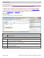
1
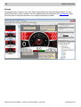
Display Creator
- Graphics Software for Customising Colour Displays
USER MANUAL
Printed documents are not controlled
While every effort has been taken to ensure correctness, MoTeC, its employees, contractors and authorised
representatives and agents take no responsibility, make no express or implied guarantees, representations or
warranties to any third party in relation to consequences arising from any inaccuracies or omissions in this
document.
This is a proprietary document and the property of MoTeC Pty. Ltd. This publication in its unaltered and original
state, may be printed, stored in any retrieval system and transmitted by any means.
MoTeC reserves the right to make changes to this document without notice.
Copyright 2014
All rights reserved.
Table of Contents
Copyright ...............................................................................2
Introduction
..........................................................................5
About CAN Signals and Channels
......................................................6
How to Create a Display Configuration
Functional Overview
.................................................7
..................................................................8
About Element Selection
..............................................................9
About Origin Points...................................................................10
About Alarms ........................................................................10
Display Creator Tabs .................................................................11
Settings Tab ............................................................................11
Channels & Functions Tab ...................................................................12
Communications Tab ......................................................................13
Alarms Tab .............................................................................16
Pages Tab ..............................................................................19
Page Management and Properties .........................................................21
Overlay Page ........................................................................23
Page Elements .......................................................................24
Selecting Elements on a Page ................................................................25
Right-Click Menu Element Placement Functions ....................................................26
Rectangle ..............................................................................29
Ellipse.................................................................................30
Image .................................................................................31
Static Text .............................................................................32
Channel Value ...........................................................................33
Horizontal Bar Graph.......................................................................34
Create Representative Tick Mark Text ......................................................35
Creating a Non-Linear Progression .........................................................37
Adding Sweeps ......................................................................38
Vertical Bar Graph ........................................................................39
Create Representative Tick Mark Text ......................................................41
Creating a Non-Linear Progression .........................................................42
Adding Sweeps ......................................................................43
Dial ..................................................................................44
Create Representative Tick Mark Text ......................................................46
Creating a Non-Linear Progression .........................................................47
Adding Sweeps ......................................................................48
Switch ................................................................................49
Alarm Displays ..........................................................................52
Alarm Elements ......................................................................53
www.motec.com
Display Creator User Manual – MoTeC Ⓒ 2014 Published 1 July 2014
4
MoTeC
Alarm Icon Element ...................................................................54
Alarm Message Element ................................................................54
Alarm Channel Value Element ............................................................55
Importing a DBC file ..................................................................56
Initial Import of a DBC File ..................................................................56
Subsequent Imports of a DBC File .............................................................58
Updating a DBC File Import ..................................................................60
Imported DBC File Alarms ...................................................................63
Project Validation ....................................................................65
Configure Device .....................................................................65
Troubleshooting ......................................................................66
Display Creator User Manual – MoTeC Ⓒ 2014 Published 1 July 2014
www.motec.com
Introduction
5
Introduction
Display Creator is a unique application used to design and create custom display configurations for MoTeC's D
series displays and C series display loggers.
It has versatile and powerful graphical creation functions that allow the configuration of all display elements.
Many of the functions are self explanatory, and onscreen assistance is provided.
See the following three topics before starting a Display Creator project.
About CAN Signals and Channels
How to Create a Display Configuration. This topic includes automatic quick setup.
Functional Overview
Help and Samples
The purpose of this help system is to provide an understanding of Display Creator concepts, and the information
necessary to create a display configuration. However, it is not possible to cover the extensive flexibility built into
the system, or the many options available. Therefore, in conjunction with using this help, it is highly
recommended to analyse the sample projects that ship with Display Creator, and watch the various webinars
provided by MoTeC.
This link is to all available webinars, including Display Creator — webinars.
To open a sample project:
1.
Select File > New.
2.
Select the device model for which the display is required.
3.
Select a sample from the Template list.
4.
Click OK.
☛ To gain an understanding of how to create a display, read this help and then methodically deconstruct one of
the samples.
www.motec.com
Display Creator User Manual – MoTeC Ⓒ 2014 Published 1 July 2014
6
About CAN Signals and Channels
About CAN Signals and Channels
☛ Messages, signals and channels can be manually created and set up, or automatically added by importing
the DBC file created in Dash Manager when a Dash/Logger configuration is saved. See Importing a DBC file
Not all signals need to be assigned to channels. Unassigned signals are not received.
See the following for a depiction of the functional process flow:
How to Create a Display Configuration
Functional Overview
Display Creator User Manual – MoTeC Ⓒ 2014 Published 1 July 2014
www.motec.com
How to Create a Display Configuration
7
How to Create a Display Configuration
To create a functioning display the following tasks are required.
☛ The tasks, sequence and dependencies shown below are provided to indicate functional relationships. Pages,
elements, channels etc. can be created, deleted, modified at any time, and at will.
Setup
It is best to define the display device and default font before performing any of the tasks below, see Settings
Tab. Changing the device after creating a display configuration will automatically resize all elements so as to fit
on the device's screen.
Task
When
Reference Links
1
* Setup communications (messages and signals)
Any time before 12
Communications Tab
Importing a DBC file
2
* Setup channels for use in the display elements
Any time before any of 3, 6, 7, 10, 11, 12
Channels & Functions Tab
Importing a DBC file
3
* Assign channels to signals
After 1 and 2
Communications Tab
Importing a DBC file
4
Create pages (each page covers the whole screen)
Any time
Pages Tab
5
Create page display elements
Any time
Page Elements
6
Assign channels to display elements on each
relevant page
After 2
7
Define conditions on which pages are displayed
After 2
Pages Tab
8
Create alarm displays (these are placed on pages)
Any time
9
Create/modify alarm display elements
Any time after 8
About Alarms
Alarm Displays
Alarm Elements
10
** Assign channels to alarm display elements
After 2
11
Define alarm conditions
After 2
12
Validate and configure device
Validate any time during creation to check
Project Validation
for issues. Configure device when ready, an Configure Device
automatic validate step occurs first.
Configuration must be valid before the
system sends the display configuration to
the device.
Use this link to view a webinar showing the creation of a basic configuration using a DBC file, webinar_DBC.
* For C Series display/loggers, these tasks can be automatically performed by importing the DBC file that is
automatically generated by Dash Manager. If required, manual adjustments can still be made. See Importing a
DBC file. For D Series displays, importing a DBC file is not applicable. However, a quick display can be setup by
using one of the provided samples. See Introduction.
** For C Series display/loggers, if a DBC file is imported, all alarms are automatically set to display in the
Alarm Display element on the Overlay Page. See Overlay Page
www.motec.com
Display Creator User Manual – MoTeC Ⓒ 2014 Published 1 July 2014
8
Functional Overview
Functional Overview
The process flow and functions involved in creating a display are depicted in the following diagram. Details on
the use of each tab, and the elements associated with them, are provided in the relevant topic within this help
file.
Display Creator User Manual – MoTeC Ⓒ 2014 Published 1 July 2014
www.motec.com
About Element Selection
9
About Element Selection
This topic applies to selection of elements on a page. As Display Creator does this in a unique way, it is
provided here as a preamble. Some of the operations used to select elements in Display Creator are unique.
Such as:
• Select an element from the element tree list, see Page Elements.
• Click repeatedly on an element at one location on the page. This will sequentially select (drill down) each
element whose boundaries encompass the cursor location. When the selection reaches the lowest element
in the hierarchy, the selection loops back to the first element. It does not necessarily drill down through
every element on the page. A more precise method of selecting a specific element is to select it in the
hierarchical element tree.
See Selecting Elements on a Page for more information.
www.motec.com
Display Creator User Manual – MoTeC Ⓒ 2014 Published 1 July 2014
10
About Alarms
About Origin Points
This topic applies to alignment of elements on a page. As Display Creator does this in a unique way, it is
provided here as a preamble. See Page Elements for more information.
Element Origin Points
All elements that can be included in a display have an origin point, this point is used for the alignment of
elements. By default, text based elements have an origin point at the top left corner of the element (this can be
changed via the element's properties, as an example, see Static Text). All other elements have an origin point in
the centre of the element, this cannot be changed, however, the alignment of these elements is internally
calculated so that alignment is based on the element's border.
The distinction is that text elements will align using the location of the origin point.
For example:
Take these two selected elements
, the origin point for the Text element is at the bottom left.
Aligning the elements to top has the following effect
the origin point of the Text element.
, the top of the rectangle is aligned with
About Alarms
Managing alarms in Display Creator can be summarised as follows:
• Required alarms, and the conditions which make them active, are defined on the Alarms tab. See Alarms
Tab.
• Any number of alarms are then assigned to any number of Alarm Display elements, see Alarm Displays.
• An Alarm Display element is a parent element that can contain Alarm Icon, Alarm Message and/or Alarm
Channel Value elements. See Alarm Elements.
When an alarm becomes active, the appropriate Alarm Display and its child elements display the alarm
information.
• Multiple Alarm Displays can be placed on the Overlay Page and on any other page(s). See Overlay Page
and Pages Tab.
Display Creator User Manual – MoTeC Ⓒ 2014 Published 1 July 2014
www.motec.com
Display Creator Tabs
11
Display Creator Tabs
Display Creator contains six tabs required to create a display configuration. That is,
•
•
•
•
•
•
Settings
Communications
Channels & Functions
Alarms
Pages
Images
Settings Tab
Defines the display or logger device for which the display configuration is being created. Changing the device
will automatically resize all elements so as to fit on the device's screen.
The default font used for the configuration is also specified on this tab. The display configuration is not valid and
cannot be sent to the device if a default font is not specified.
A green tick in the font icon
indicates that it is a Windows system font. As such, there
is certainty that these fonts will be available if the project is moved to another PC.
www.motec.com
Display Creator User Manual – MoTeC Ⓒ 2014 Published 1 July 2014
12
Display Creator Tabs
Channels & Functions Tab
This tab allows manual creation of channels. These are subsequently assigned to signals.
☛ Messages, signals and channels can be automatically created for use in Display Creator by importing the
DBC file created in Dash Manager when a Dash/Logger configuration is saved. See Importing a DBC file.
The properties displayed for this tab vary depending on the element selected.
Channel Properties
Channel "name"
Name
Name given to the channel. As this will be assigned to a signal, it is recommended to use a name that corresponds
to the signal.
Value
Data Type
Used to specify the expected format of the received value or an enumeration.
Quantity
Used to specify the class of data expected for the channel.
Display
Unit
Unit chosen for the applicable type of channel (signal).
Enumeration Properties
Enumeration Value
Name
Name given to the enumeration.
Value
Value of the enumeration.
Display Creator User Manual – MoTeC Ⓒ 2014 Published 1 July 2014
www.motec.com
Display Creator Tabs
13
Communications Tab
This tab allows manual setup of CAN messages and signals, and the assignment of channels.
☛ Messages, signals and channels can be automatically created for use in Display Creator by importing the
DBC file created in Dash Manager when a Dash/Logger configuration is saved. See Importing a DBC file.
The properties displayed for this tab vary depending on whether the Message or Signal element is selected, as
shown in the Message Element and Signal Element examples.
Message Element
These are the properties with a message element selected.
Message "name"
Name
Name given to the message. The name could identify the type of data transmitted in this message, or some other
aspect that is relevant.
Message
Address Type
Two formats of message ID exist. Standard, which uses 11 bit and has values between 0 and 2047. Extended has
29 bit and has values between 0 and 536870911.
Address
The Address value tells all other devices what to associate the incoming data with based on their internal databases
All addresses should be shown as hexadecimal numbers.
Packet Format For signals containing more than 8 bits (1 byte) of data, the byte order can be either most significant data in the
lower byte offset or most significant data in the higher byte. Lower byte is specified by selecting Big Endian, higher
byte by selecting Little Endian.
Receive Rate
Default is 50 Hz and can be user configured.
www.motec.com
Display Creator User Manual – MoTeC Ⓒ 2014 Published 1 July 2014
14
Display Creator Tabs
Compound
Optionally, a message may contain further addressing of the signals by extending the address into the data section of the message.
The location of the compound address is specified, and signals associated with this message must match the Address and the
Compound ID.
Compound Checkbox — Check to identify use of extended addressing.
Compound ID
A compound address value for associated channels.
Type
Used to set the format of the received value. Unsigned integer values are absolute, containing values from 0 to max
for the bit length of the signal. Integer values use the two's complement format giving negative and positive values
in equal proportions.
Offset
The Offset and Length settings tell the device where the compound ID is within the message.
Length
Signal Element
☛ Messages, signals and channels can be manually created and set up, or automatically added by importing
the DBC file created in Dash Manager when a Dash/Logger configuration is saved. See Importing a DBC file
Not all signals need to be assigned to channels. Unassigned signals are not received.
These are the properties with a Signal element selected.
A signal can be a single bit, or number of bits of the data transmitted in the data section of a CAN message.
The data section contains up to 8 bytes, or 64 bits of data. A signal can comprise between 1 and 32 bits of the
entire 64 bits of data.
General
Name
User defined name given to the signal.
Signal
Channel
The Display Creator channel associated with this signal. The selection list is populated from the channels created in
the Channel & Functions tab.
Display Creator User Manual – MoTeC Ⓒ 2014 Published 1 July 2014
www.motec.com
Display Creator Tabs
15
Location
Type
Used to set the format of the received value. Unsigned integer values are absolute, containing values from 0 to max
for the bit length of the signal. Integer values use the two's complement format giving negative and positive values
in equal proportions.
Offset
Length
To identify the unique signal, the Offset and Length settings tell the device where to find this signal within the
message, based on the order in which the data is received.
Conversion
Once the signal has been received, the raw numeric value can be determined. This value can then be scaled using the Multiplier and
added to using the Offset to convert the raw value into the final channel value in a real unit of measurement specified by the quantity
and unit.
For example:
Sending engine temperature as an integer, where 0 == 0 degrees, and 1000 == 100 degrees.
A multiplier of 0.1 is required to convert this to a floating point signal containing 0.0 to 100.0 degrees.
☛ Conversions are applied to signal values in two steps:
1.
Scaled Value = (Signal Value * Multiplier + Offset).
2.
Final Value = Scaled Value converted to the specified Quantity.
For example:
A signal with a multiplier of 0.1, offset of 50 and a Quantity & Unit of speed and miles/hour respectively are converted as follows:
Scaled Value = Signal Value * 0.1 + 50.
Final Value = Scaled Value * 0.44704 metres/second.
Multiplier
A scaling factor applied to the raw CAN value.
Offset
Amount added to resulting value after the multiplier.
Quantity
Used to specify the class of data on which to apply the conversion.
For example, temperature.
Unit
The unit to convert to for the quantity selected.
For example, K (Kelvin).
www.motec.com
Display Creator User Manual – MoTeC Ⓒ 2014 Published 1 July 2014
16
Display Creator Tabs
Alarms Tab
The Alarms tab is used to create any number of alarms.
☛ Although an alarm is created and its condition may become true, it will not display unless it has been
assigned to an Alarm Display element, see Alarm Displays. By default, all alarms created on the Alarm tab
are automatically selected to display in Alarm Display elements on the Overlay Page. Therefore, at the
simplest level, all that is required to display an alarm is to create it.
Any number of Alarm Display elements may be added to the Overlay Page or any other page. See Overlay
Page and Pages Tab
When a single Alarm Display element has a number of alarms assigned to it, and more than one of these
alarms become active at the same time, the alarm that is higher on the Alarms tab list will display. If in the
meantime another alarm becomes active that is higher on the list, that alarm will immediately replace the
currently displayed alarm.
If Alarm Display elements are included on pages other than the Overlay Page, the alarm will only become visible
if that page is also the one that is currently displayed. However, that same alarm will nevertheless display on
the Overlay Page and be visible (unless it has been deselected). Therefore, the possibility exists that the same
alarm could be displayed twice.
Display Creator User Manual – MoTeC Ⓒ 2014 Published 1 July 2014
www.motec.com
Display Creator Tabs
17
Alarm Properties
General
Critical Checkbox — Check this to ensure the alarm displays when active. Non critical alarms may not display in some situations.
Name
Descriptive name given to the alarm.
www.motec.com
Display Creator User Manual – MoTeC Ⓒ 2014 Published 1 July 2014
18
Display Creator Tabs
Condition
Contains the statements that specify the conditions under which the alarm becomes active.
Add
Use to add a condition expression. The Add Condition dialogue box displays as shown in the image above.
☛ A sequence of condition expressions can be inserted and connected by And or Or statements.
Add Condition Dialogue Box
Channel
For selecting a display channel defined on the Channels & Functions tab.
Is
To insert the required operator (==, !=, <, <=, >, >=)
Channel or
Value
For selecting a display channel or value that the operator is applied to.
Inverse Result — Check this to make the condition true when the defined condition expression evaluates to false.
Remove
Removes the selected expression.
Edit
Use to edit an existing condition. The Edit Condition dialogue box displays, which is identical to Add Condition
dialogue box.
Moves a selected expression up or down.
Remove All
Removes all condition expressions.
Display Message
Show Message Checkbox — Check this to enter a message that is to display when the alarm becomes active. The Alarm Display
element used for the alarm must have an Alarm Message element associated with it in order to display the message.
Show Icon Checkbox — Check this to select an icon to display when the alarm becomes active. The Alarm Display element used
for the alarm must have an Alarm Icon element associated with it in order to display the icon.
Change
Change the selected icon.
Display Channel Value
Used to specify a channel value to display when the alarm becomes active. The Alarm Display element used for the alarm must
have an Alarm Channel Value element associated with it in order to display the value.
Channel
Used to select the display channel to use.
Format
Format of the value (either numeric or time format). Formats offered are those that are applicable to the selected
display channel.
DPS
The number of decimal points to which the value should extend.
Flash
Used to define the flash behaviour for the alarm message when the alarm becomes active.
When alarm is Used to choose the circumstances under which the alarm message should flash.
active
On Time
The amount of time the alarm message will display between flashes.
Off Time
The amount of time the alarm message will not display between flashes.
Condition
Contains the statements that specify the conditions under which the alarm message should flash. For this to have
an effect Flash if condition is true option must be selected in the When alarm is active field.
Display Creator User Manual – MoTeC Ⓒ 2014 Published 1 July 2014
www.motec.com
Display Creator Tabs
19
Pages Tab
The pages defined on this tab comprise the displays available for the current project.
The Properties pane at the right side of the Display Creator window will change depending on what is
selected. For information on management and properties of a page, see Page Management and Properties. For
information on the properties of individual elements see the Page Elements topics.
☛ All pages are initially created by the user, except for the Overlay Page, which always overlays the currently
displayed page. A project can contain any number of pages but only one Overlay Page.
Default page
The Default Page is the first page listed in the Navigation (Pages) pane that does not have any display
conditions assigned to it in the Switched Element section of the Properties pane.
Page display (switching) criteria
A device that uses a Display Creator project will display pages according to the following criteria:
• The page displayed is the page whose display conditions are true, however:
○ If more than one page has conditions that evaluate as true, then the page highest on the list displays.
○ If there are no pages whose conditions evaluate as true, then the Default Page displays.
○ If a Default Page does not exist, and there are no pages whose display conditions are true, then only
the Overlay Page displays.
☛ Although a condition expression can use any channel to switch pages automatically, a convenient method to
manually switch pages is to use channels assigned to push buttons.
www.motec.com
Display Creator User Manual – MoTeC Ⓒ 2014 Published 1 July 2014
20
Display Creator Tabs
Example
The example below is similar to one of the sample configurations that ships with Display Creator. For more
detailed information of what is possible, see the individual element help provided in the Page Elements topics.
Also, take time to study the construction of the sample configurations available.
Display Creator User Manual – MoTeC Ⓒ 2014 Published 1 July 2014
www.motec.com
Display Creator Tabs
21
Page Management and Properties
Pages are created and managed as discreet elements. The properties of each page apply just to that page. The
sections below cover managing pages, and their properties.
Page Management
Page management includes functions such as adding, deleting and arranging page order. Page management is
done by selecting a page in the Navigation (Pages) pane and using the right-click menu to add, copy, cut,
paste, delete and move pages, or by using the buttons at the top of the Navigation (Pages) pane
.
Page Properties
Page properties are of two types, firstly those that govern how the page displays in Display Creator, and then
those that govern the operation, and the look and feel in the finalised project.
Properties that govern how the page displays in Display Creator
Show Invisibles checkbox
Uncheck this so that dotted outlines identifying non-visible elements are not shown.
Snap to grid checkbox
Check this so that elements snap to, or are positioned in reference to the grid. It is recommended to
use snap to grid. It may be turned off from time to time to allow minute positioning of elements,
however, minute positioning is best done using an element's position properties.
Snap to grid value
Determines how fine or coarse the grid is, default is 5.
Manual zoom
Manually select zoom level.
Preset zoom levels
These are respectively 100%, 200% and 400%
Fit will resize to the maximum space available in the Display Creator window.
Actual will resize to the actual dimensions of the device for which the display is being created. This
gives the best representation of the size of the display.
www.motec.com
Display Creator User Manual – MoTeC Ⓒ 2014 Published 1 July 2014
22
Display Creator Tabs
Properties that govern the created display configuration
Page '[name]'
Name Descriptive name given to the page. Default is Page n,
where n is an incremental sequential number used for each
added page.
Border
Show Border checkbox — Check this so that the defined
border is shown. Elements on the page can overlap and display
in front of the border.
Fill
Colour, graduated shading using two colours, and opacity can
be applied.
Switch Element
This is where channel conditions are expressed for the currently
selected element in a switch or for a page. For an element in a
switch, the element is displayed if the conditions are true. For a
page, the page is displayed if the conditions are true.
Elements
This is a hierarchical tree view of all elements on the page. Use
the right-click menu and the buttons provided to manipulate the
elements as required.
☛ The order in which elements are displayed indicates their
layer on the page. At the top of this list is the front layer
and the bottom the back. How elements display when
overlapped is dependant on this layer order.
Display Creator User Manual – MoTeC Ⓒ 2014 Published 1 July 2014
www.motec.com
Display Creator Tabs
23
Overlay Page
On a device, the Overlay Page is always displayed and overlays the current page. Its background is 100%
transparent.
By default the Overlay Page contains an Alarm Display element that has all alarms assigned (selected), see
Alarms Tab and Alarm Displays. The Alarm Display element will only become visible if one of the alarms
associated with it becomes active. All other elements on this page that are not part of an Alarm Display
element will always be visible.
Any of the elements that can be included on a page can also be included on the Overlay Page.
☛ The Overlay Page allows for powerful presentation options, such as allowing common elements to display on
every page. A significant amount of development time can be saved by using this technique.
For example: a Dial element placed on the Overlay Page will display on every page, with the design
around the dial varying depending on the page it overlays.
www.motec.com
Display Creator User Manual – MoTeC Ⓒ 2014 Published 1 July 2014
24
Page Elements
Page Elements
Elements can be added to a page, these and their specific properties are described in subsequent topics. Also,
there are a number placement functions that can be applied to elements, and these are only available via the
right click menu. See Right-Click Menu Element Placement Functions.
It is important to understand two other aspects of element management, the origin points and the elements tree.
Element Origin Points
All elements that can be included in a display have an origin point, this point is used for the alignment of
elements. By default, text based elements have an origin point at the top left corner of the element (this can be
changed via the element's properties, as an example, see Static Text). All other elements have an origin point in
the centre of the element, this cannot be changed, however, the alignment of these elements is internally
calculated so that alignment is based on the element's border.
The distinction is that text elements will align using the location of the origin point.
For example:
Take these two selected elements
, the origin point for the Text element is at the bottom left.
Aligning the elements to top has the following effect
the origin point of the Text element.
, the top of the rectangle is aligned with
Elements Tree
The elements tree is a hierarchical view of all elements on the
page. All operations that can be done to an element directly by
selecting the element on the page can also be done via selecting
the element in this view. It is a convenient method of selecting
an element (especially in a complex display), and can be used for
cutting, copying, pasting and deleting.
☛ This view also depicts the Z-Order, which is the depth of
each element or group of elements. The higher in the list an
element or group is placed, the closer it is to the front, the
element at the top of the list will display in front of any other
element. The depth can be adjusted using the right-click
menu, drag-and-drop, or the arrows available at the top of
the list.
Display Creator User Manual – MoTeC Ⓒ 2014 Published 1 July 2014
www.motec.com
Page Elements
25
Selecting Elements on a Page
Selecting elements on a page
The various methods for selecting elements are:
• Individually click an element on a page
• Select a number of elements by dragging the cursor over the page to enclose a group of elements
• Select an element from the element tree list, see Page Elements.
• Click repeatedly on an element at one location on the page. This will sequentially select (drill down) each
element whose boundaries encompass the cursor location. When the selection reaches the lowest element
in the hierarchy, the selection loops back to the first element. It does not necessarily drill down through
every element on the page. A more precise method of selecting a specific element is to select it in the
hierarchical element tree.
Selecting elements that are part of a Switch element
Only one individual element in a Switch element can be selected at one time. Multiple elements within a
Switch element cannot be selected as a group. To select these:
1.
Select the Switch.
2.
Select the required element from the Navigation (Switch) pane.
www.motec.com
Display Creator User Manual – MoTeC Ⓒ 2014 Published 1 July 2014
26
Page Elements
Right-Click Menu Element Placement Functions
Apart from specific element properties, there are a number of element placement functions that can be applied
to elements, these are only available via the right-click menu. All functions (other than Z-Order), require more
than one element to be selected. The Z-Order function is only available for single element or parent element
selections (child elements move with the parent). The functions are described below.
Grouping
Allows a selection of elements to be grouped so that they can be manipulated as one object, such as moving
the whole group forward or backward (Z-Order), these appear in the elements tree as a group folder. Elements
that are grouped can still be moved independently to any location.
Z-Order
The Z-Order, which is the layer depth of each element or group of elements. The order is displayed in the
elements tree, the higher in the list an element or group is placed, the closer it is to the front, the element at
the top of the list will display in front of any other element.
The functions below operate according to the following criteria:
• All elements will move relative to the first selected element (does not apply to Spacing), – that is, the first selected element
will remain stationary and all other elements will move as required to achieve the result (e.g. alignment).
• With Switch elements, all functions operate on the Switch, not on the elements in the Switch.
However, the elements in the Switch might be affected. For example, if the Switch size changes, the elements in the Switch
will resize relative to the changed size of the Switch (but not text based elements).
• Origin points are used in determining element arrangement, see Element Origin Points
Alignment
Aligns a selection of elements. An alignment can be applied, and then another alignment can be applied to the
resulting alignment.
In these examples, the blue rectangle is the first selected element.
Using this
selection as
the starting
arrangement:
Align left
results in:
Align right
results in:
Align top
results in:
Align bottom
results in:
Align vertical
centre
results in:
Align
horizontal
centre
results in:
Display Creator User Manual – MoTeC Ⓒ 2014 Published 1 July 2014
www.motec.com
Page Elements
Sizing
27
Resizes all selected elements to either the width or the height of the first selected element (this function is not
available for text based elements).
☛ Resize occurs from the origin point – that is, the size is calculated from the element centre, not at a
border.
In these examples, the blue rectangle is the first selected element.
For example, using
this selection as
the starting
arrangement:
Make same width
results in
Note that the text is not resized.
Make same height
results in
www.motec.com
Display Creator User Manual – MoTeC Ⓒ 2014 Published 1 July 2014
28
Spacing
Page Elements
Equally spaces elements, or removes spaces between elements.
For example
(HORIZONTAL),
using this selection
as the starting
arrangement:
Equal horizontal
spacing results in
Elements between the two outside
elements moved to create equal spacing.
Remove horizontal
spacing results in
Elements moved from right to left.
For example
(VERTICAL), using
this selection as
the starting
arrangement:
Equal vertical
spacing results in
Elements between the top and bottom elements moved to create equal
spacing.
Remove vertical
spacing results in
Display Creator User Manual – MoTeC Ⓒ 2014 Published 1 July 2014
www.motec.com
Page Elements
29
Elements moved from bottom to top.
Rectangle
Rectangle
Left
Space between the left margin of the page and the
left border of the element in pixels.
Top
Space between the top margin of the page and the
top border of the element in pixels.
Width
Width of the element in pixels. Change in
dimension occurs at the right border, left border
position remains static.
Height
Height of the element in pixels. Change in
dimension occurs at the bottom border, top border
position remains static.
Centre
Fit
Centres the element on the page.
Centres the element and then fits the borders to
the edges of the page.
Border
Properties to set border characteristics.
Fill
Properties to set fill characteristics.
www.motec.com
Display Creator User Manual – MoTeC Ⓒ 2014 Published 1 July 2014
30
Page Elements
Ellipse
Ellipse
Left
Space between the left margin of the page and the
left border of the element in pixels.
Top
Space between the top margin of the page and the
top border of the element in pixels.
Horizontal
Diameter
Horizontal width of the element in pixels. Change in
dimension occurs at the right border, left border
position remains static.
Vertical
Diameter
Vertical height of the element in pixels. Change in
dimension occurs at the bottom border, top border
position remains static.
Centre
Fit
Centres the element on the page.
Centres the element and then fits the borders to
the edges of the page.
Border
Properties to set border characteristics.
Fill
Properties to set fill characteristics.
Display Creator User Manual – MoTeC Ⓒ 2014 Published 1 July 2014
www.motec.com
Page Elements
31
Image
Image
Left
Space between the left margin of the page and the
left border of the element in pixels.
Top
Space between the top margin of the page and the
top border of the element in pixels.
Width
Horizontal width of the element in pixels. Change in
dimension occurs at the right border, left border
position remains static.
Height
Vertical height of the element in pixels. Change in
dimension occurs at the bottom border, top border
position remains static.
Centre
Fit
Reset
Centres the element on the page.
Centres the element and then fits the borders to
the edges of the page.
Reset the image to its original size.
Properties
Set the opacity of the element, 0 is fully transparent, 255 is fully
opaque.
www.motec.com
Display Creator User Manual – MoTeC Ⓒ 2014 Published 1 July 2014
32
Page Elements
Static Text
Used to display text.
Text
X
Space between the left margin of the page and the
origin point (see Element Origin Points) of the
element in pixels.
Y
Space between the top margin of the page and the
origin point of the element in pixels.
Centre
Text
Places the origin point of the element at the centre
of the page.
Text to display in the element.
Appearance
Properties to set font type, size, style and colour characteristics.
The
icons are used to move the
text relative to the origin point. The dot represents the origin
point and the lines the relative position of the text. The first
three govern the horizontal position and the last three govern
the vertical position of the text. See Element Origin Points.
Display Creator User Manual – MoTeC Ⓒ 2014 Published 1 July 2014
www.motec.com
Page Elements
33
Channel Value
This element is used to display a selected channel value.
Text
X
Space between the left margin of the page and the
origin point (see Element Origin Points) of the
element in pixels.
Y
Space between the top margin of the page and the
origin point of the element in pixels.
Centre
Places the origin point of the element at the centre
of the page.
Channel
Channel
Used to select the channel whose value is to
display in the element.
Format
The format the value is to take. This is either a
numeric or time format. If the channel can only be
represented as numeric, then this is automatically
set and cannot be changed.
DPS
The amount of decimal places allowed for the
value.
Refresh Rate
Used to specify how frequently the value is refreshed.
Appearance
Properties to set font type, size, style and colour characteristics.
The
icons are used to move the
text relative to the origin point. The dot represents the origin
point and the lines the relative position of the text. The first
three govern the horizontal position and the last three govern
the vertical position of the text. See Element Origin Points.
www.motec.com
Display Creator User Manual – MoTeC Ⓒ 2014 Published 1 July 2014
34
Page Elements
Horizontal Bar Graph
A Horizontal Bar Graph element graphically displays the value of the assigned channel as it varies. This
element is ideal for purposes such as a Gain/Loss bar.
Note the following:
• Each graphical component of the bar graph (as shown in the elements tree), including tick marks and text
values can be formatted and moved anywhere on (or off) the page.
• The bar graph bar is the component of the bar graph to which the input channel is assigned.
• Start and end values, major and minor divisions, and tick text, can all be configured.
• The bar graph can be setup in a non linear progression.
For example: 0, 20, 30, 40, 45, 50, 55, 60, 65 etc.
Linear and non-linear progressions
All progressions are initially linear, as defined in the Configure Ticks window (explained below). A non-linear
progression, as mentioned above, can be defined after the linear bar graph is created. See Creating a Non-Linear
Progression.
☛ The Configure Ticks window only defines linear progressions. If it is used after non-linear adjustments are
made, it will revert the progression to linear, and the non-linear adjustments will be lost.
Adjusting direction of fill
The direction in which the bar fills can be selected from the properties pane (left to right or right to left).
However, the start and end values need to be manually changed in the Configure Ticks window (explained
below) to change the progression to fit the purpose. See the following example:
Configuring Ticks
When a bar graph is first created, a Configure Ticks window displays. This can also be displayed later by
selecting the Configure Ticks button on the Properties pane.
Display Creator User Manual – MoTeC Ⓒ 2014 Published 1 July 2014
www.motec.com
Page Elements
35
☛ The Configure Ticks window displays the current configuration, but not any non-linear adjustments. It will
always adjust the configuration to a linear progression based on the values and configuration selected.
Major Divisions
Set the number of major divisions (does not include the initial
position) and the start and end values. Ten would give 11
positions including the start.
Tick Text
The ticks can be same as the value or different.
Minor Divisions
Set whether minor divisions are required and the number of
divisions between each major division.
Create Representative Tick Mark Text
Sometimes the tick mark text is best shown as text that is representative of the actual value, such as on a
tachometer (which is the displayed text x1000). The method for doing this is shown in the following example.
This configuration gives the result shown at right.
www.motec.com
Display Creator User Manual – MoTeC Ⓒ 2014 Published 1 July 2014
36
Page Elements
This configuration gives the result shown at right.
Display Creator User Manual – MoTeC Ⓒ 2014 Published 1 July 2014
www.motec.com
Page Elements
37
Creating a Non-Linear Progression
To create a non-linear progression, such as in the example below:
1.
Create an appropriate linear horizontal bar graph.
2.
For each required major division:
(a) Select the tick mark.
(b) In the Properties pane, change the Value to what is required.
(c) Select the tick mark text.
(d) In the Properties pane, change the Text to what is required.
For example:
☛ The Configure Ticks window only defines linear progressions. If it is used after non-linear adjustments are
made, it will revert the progression to linear, and the non-linear adjustments will be lost.
www.motec.com
Display Creator User Manual – MoTeC Ⓒ 2014 Published 1 July 2014
38
Page Elements
Adding Sweeps
Sweep elements are bracketed sections of the bar graph that can be used as visual cues. In the example
below, four sweeps are added with varying properties such as no fill, and various offset, Z-Order and width
settings.
To include a sweep on a bar graph:
1.
Select the bar graph.
2.
From the right-click menu, select Insert > New Sweep.
☛ The sweep will not display on the bar graph unless a start and end value is entered.
Sweep
Offset
With positive offset changes, the sweep moves
down relative to the bottom edge of the bar, with
negative changes the sweep moves up relative to
the bottom edge of the bar.
Width
As the width changes, the bottom border of the
sweep either expands or retracts while the top
border remains stationary.
Start
Value
Where to begin the sweep.
End
Value
Where to end the sweep.
Border
Use to set the border characteristics as required.
Fill
Use to set the border characteristics as required.
Display Creator User Manual – MoTeC Ⓒ 2014 Published 1 July 2014
www.motec.com
Page Elements
39
Vertical Bar Graph
A Vertical Bar Graph element graphically displays the value of the assigned channel as it varies. This element
is ideal for purposes such as a temperature or pressure bar.
Note the following:
• Each graphical component of the bar graph (as shown in the elements tree), including tick marks and text
values can be formatted and moved anywhere on (or off) the page.
• The bar graph bar is the component of the bar graph to which the input channel is assigned.
• Start and end values, major and minor divisions, and tick text, can all be configured.
• The bar graph can be setup in a non linear progression.
For example: 0, 20, 30, 40, 45, 50, 55, 60, 65 etc.
Linear and non-linear progressions
All progressions are initially linear, as defined in the Configure Ticks window (explained below). A non-linear
progression, as mentioned above, can be defined after the linear bar graph is created. See Creating a Non-Linear
Progression.
☛ The Configure Ticks window only defines linear progressions. If it is used after non-linear adjustments are
made, it will revert the progression to linear, and the non-linear adjustments will be lost.
Adjusting direction of fill
The direction in which the bar fills can be selected from the properties pane (left to right or right to left).
However, the start and end values need to be manually changed in the Configure Ticks window (explained
below) to change the progression to fit the purpose. See the following example:
www.motec.com
Display Creator User Manual – MoTeC Ⓒ 2014 Published 1 July 2014
40
Page Elements
Configuring Ticks
When a bar graph is first created a Configure Ticks window displays, this can also be displayed later by
selecting the Configure Ticks button on the Properties pane.
☛ The Configure Ticks window displays the current configuration, but not any non-linear adjustments. It will
always adjust the configuration to a linear progression based on the values and configuration selected.
Major Divisions
Set the number of major divisions (does not
include the initial position) and the start and end
values. Ten would give 11 positions including the
start.
Tick Text
The ticks can be same as the value or different.
Minor Divisions
Set whether minor divisions are required and the
number of divisions between each major division.
Display Creator User Manual – MoTeC Ⓒ 2014 Published 1 July 2014
www.motec.com
Page Elements
41
Create Representative Tick Mark Text
Sometimes the tick mark text is best shown as text that is representative of the actual value, such as on a
tachometer (which is the displayed text x1000). The method for doing this is shown in the following example.
This configuration gives the result shown at right.
This configuration gives the result shown at right.
www.motec.com
Display Creator User Manual – MoTeC Ⓒ 2014 Published 1 July 2014
42
Page Elements
Creating a Non-Linear Progression
To create a non-linear progression, such as in the example below:
1.
Create an appropriate linear horizontal bar graph.
2.
For each required major division:
(a) Select the tick mark.
(b) In the Properties pane, change the Value to what is required.
(c) Select the tick mark text.
(d) In the Properties pane, change the Text to what is required.
For example
☛ The Configure Ticks window only defines linear progressions. If it is used after non-linear adjustments are
made, it will revert the progression to linear, and the non-linear adjustments will be lost.
Display Creator User Manual – MoTeC Ⓒ 2014 Published 1 July 2014
www.motec.com
Page Elements
43
Adding Sweeps
Sweep elements are bracketed sections of the bar graph that can be used as visual cues. In the example
below, four sweeps are added with varying properties such as no fill, and various offset, Z-Order and width
settings.
To include a sweep on a bar graph:
1.
Select the bar graph.
2.
From the right-click menu, select Insert > New Sweep.
☛ The sweep will not display on the bar graph unless a start and end value is entered.
Sweep
Offset
With positive offset changes, the sweep
moves to the right relative to the right
edge of the bar, with negative changes
the sweep moves left relative to the right
edge of the bar.
Width
As the width changes, the right border of
the sweep either expands or retracts
while the left border remains stationary.
Start
Value
Where to begin the sweep.
End
Value
Where to end the sweep.
Border
Use to set the border characteristics as required.
Fill
Use to set the border characteristics as required.
www.motec.com
Display Creator User Manual – MoTeC Ⓒ 2014 Published 1 July 2014
44
Page Elements
Dial
A Dial element graphically displays the value of the assigned channel as it varies.
Note the following:
• Each graphical component of the dial (as shown in the elements tree), including tick marks and text values
can be formatted and moved anywhere on (or off) the page.
• The pointer is the component of the dial to which the input channel is assigned.
• Start and end values, start and end angles, major and minor divisions, and tick text, can all be configured.
• The dial can be setup in a non linear progression.
For example: 0, 20, 30, 40, 45, 50, 55, 60, 65 etc.
Linear and non-linear progressions
All progressions are initially linear, as defined in the Configure Ticks window (explained below). A non-linear
progression, as mentioned above, can be defined after the linear dial is created. See Creating a Non-Linear
Progression.
☛ The Configure Ticks window only defines linear progressions. If it is used after non-linear adjustments are
made, it will revert the progression to linear, and the non-linear adjustments will be lost.
Configuring Ticks
When a dial is first created a Configure Ticks window displays, this can also be displayed later by selecting the
Configure Ticks button on the Properties pane.
Display Creator User Manual – MoTeC Ⓒ 2014 Published 1 July 2014
www.motec.com
Page Elements
45
☛ The Configure Ticks window displays the current configuration, but not any non-linear adjustments. It will
always adjust the configuration to a linear progression based on the values and configuration selected.
Dial Face
Sets the start and end of the dial relative to the zero angle
position.
Major Divisions
Set the number of major divisions (does not include the initial
position) and the start and end values. Ten would give 11
positions including the start.
Tick Text
The ticks can be same as the value or different.
Minor Divisions
Set whether minor divisions are required and the number of
divisions between each major division.
www.motec.com
Display Creator User Manual – MoTeC Ⓒ 2014 Published 1 July 2014
46
Page Elements
Create Representative Tick Mark Text
Sometimes the tick mark text is best shown as text that is representative of the actual value, such as on a
tachometer (which is the displayed text x1000). The method for doing this is shown in the following example.
This configuration gives the result shown at right.
This configuration gives the result shown at right.
Display Creator User Manual – MoTeC Ⓒ 2014 Published 1 July 2014
www.motec.com
Page Elements
47
Creating a Non-Linear Progression
To create a non-linear progression, such as in the example below:
1.
Create an appropriate linear dial.
2.
For each required major division:
(a) Select the tick mark.
(b) In the Properties pane, change the Value to what is required.
(c) Select the tick mark text.
(d) In the Properties pane, change the Text to what is required.
For example:
☛ The Configure Ticks window only defines linear progressions. If it is used after non-linear adjustments are
made, it will revert the progression to linear, and the non-linear adjustments will be lost.
www.motec.com
Display Creator User Manual – MoTeC Ⓒ 2014 Published 1 July 2014
48
Page Elements
Adding Sweeps
Sweep elements are bracketed sections of the dial that can be used as visual cues. In the example below, three
sweeps are added with varying properties such as no fill, and various radius and width settings.
To include a sweep on a dial:
1.
Select the dial.
2.
From the right-click menu, select Insert > New Sweep.
☛ The sweep will not display on the dial unless a start and end value is entered.
Sweep
Radius
As the radius changes, it moves the whole element
to, or away from the centre.
Width
As the width changes, the inner border either
expands to, or retracts from the centre.
Start
Value
Where to begin the sweep.
End
Value
Where to end the sweep.
Border
Use to set the border characteristics as required.
Fill
Use to set the border characteristics as required.
Display Creator User Manual – MoTeC Ⓒ 2014 Published 1 July 2014
www.motec.com
Page Elements
49
Switch
A Switch element controls the contents of an area of the page that is bounded by the Switch.
The Switch element can contain any element except for another Switch or an Alarm Display. Each element in
the Switch occupies the complete area of the Switch.
Elements can only be added to a Switch by selecting it, and using the right-click menu, or by selecting Add in
the Switch Navigation pane on the left.
Any number of elements can be included in a Switch, but each element must have an assigned condition.
When running on the device, the Switch will display only one of those elements. The element displayed is the
first in the list for which the condition evaluates to true. If no conditions evaluate as true, no element is
displayed.
Switch properties
Left
Space between the left margin of the page and the left border of the element in pixels.
Top
Space between the top margin of the page and the top border of the element in pixels.
Width
Horizontal width of the element in pixels. Change in dimension occurs at the right border, left border position remains
static.
Height
Vertical height of the element in pixels. Change in dimension occurs at the bottom border, top border position
remains static.
Centre
Centres the element on the page.
Fit
Centres the element and then extends the borders to the edges of the page.
www.motec.com
Display Creator User Manual – MoTeC Ⓒ 2014 Published 1 July 2014
50
Page Elements
Example of a Switch
This is an example of a fuel indicator switch that will display one of two icons based on the fuel level.
With the Switch selected
Two image elements are included in the Switch (as shown in the Switch list and Elements Tree), one of which is a low fuel image.
Display Creator User Manual – MoTeC Ⓒ 2014 Published 1 July 2014
www.motec.com
Page Elements
51
With the low fuel image element selected
The condition of this element becomes true if the channel Fluid Level is <= 25, as seen in the Switch Element pane.
www.motec.com
Display Creator User Manual – MoTeC Ⓒ 2014 Published 1 July 2014
52
Page Elements
Alarm Displays
An Alarm Display element is a parent or group element. Its child elements are used to display the alarm
information (alarms are defined on the Alarm tab) when they become active. See Alarms Tab.
More than one Alarm Display element can be included on the Overlay Page and on any other page, see Pages
Tab. This allows flexibility in the presentation of different alarms.
An Alarm Display element can have any number of the alarms from the Alarm tab associated with it. This
allows the same area on the display to be used for multiple alarms.
To setup:
1.
Place an Alarm Display element on the page.
2.
Select the Alarm Display and use the right-click menu to insert the alarm (child) elements.
☛ Only alarm elements from the Alarm Display right-click menu will be associated with the Alarm
Display.
The following applies for each Alarm Display element:
• At least one alarm should be assigned
• Inserting elements into the Alarm Display element can only be done by selecting it and using the right-click
menu. Consider the following:
○ At least one of either Alarm Icon, Alarm Message or Alarm Channel Value elements should be
inserted. See Alarm Elements
○ For graphical and informational purposes; Rectangle, Ellipse and static Text elements can also be
inserted as, or if required.
• Can contain as many Alarm icon, Alarm Message and Alarm Channel Value elements as wanted.
However, the same alarm information is displayed in each.
☛ To display information from two or more different alarms at the same time, create a separate Alarm
Display element for each alarm and assign the appropriate alarm to each.
• Any elements inserted into an Alarm Display element can be placed anywhere on the page, not necessarily
just within the bounds of the Alarm Display element. Regardless of their location, all included elements
move in relation to the Alarm Display element as it is moved.
• The appearance (background) is essentially a rectangle that cannot be deleted. It can however have its fill
hidden (making it transparent), or the fill colour opacity adjusted to suit.
Display Creator User Manual – MoTeC Ⓒ 2014 Published 1 July 2014
www.motec.com
Page Elements
53
Alarm Display
Left
Space between the left margin of the page and the
left border of the element display in pixels.
Top
Space between the top margin of the page and the
top border of the element in pixels.
Width
Horizontal width of the element in pixels. Change in
dimension occurs at the right border, left border
position remains static.
Height
Vertical height of the element in pixels. Change in
dimension occurs at the bottom border, top border
position remains static.
Centre
Fit
Centres the element on the page.
Centres the element and then fits the borders to
the edges of the page.
Selected Alarms
Use to select the alarms to display in the element.
Border
Use to set the border properties of the appearance (rectangle).
Fill
Use to set the fill properties of the appearance (rectangle).
Opacity can be set from the Fill Colour drop-down.
Alarm Elements
The Alarm Icon, Alarm Message and Alarm Channel Value elements are inserted as required into an Alarm
Display element and are the means by which alarm information is displayed when an alarm becomes active
For graphical and informational purposes; Rectangle, Ellipse and static Text elements can also be inserted.
www.motec.com
Display Creator User Manual – MoTeC Ⓒ 2014 Published 1 July 2014
54
Page Elements
Alarm Icon Element
The Alarm Icon element is a child of the Alarm Display element.
Alarm Icon
Left
Space between the left margin of the page and the
left border of the element in pixels.
Top
Space between the top margin of the page and the
top border of the element in pixels.
Width
Width of the element in pixels. Change in
dimension occurs at the right border, left border
position remains static.
Height
Height of the element in pixels. Change in
dimension occurs at the bottom border, top border
position remains static.
Centre
Fit
Centres the element on the Alarm Display.
Centres the element and then fits the borders to
the edges of the Alarm Display.
Alarm Message Element
The Alarm Message element is a child of the Alarm Display element.
Alarm Message
X
Space between the left margin of the Alarm
Display and the origin point (see Element Origin
Points) of the element in pixels.
Y
Space between the top margin of the Alarm
Display and the origin point of the element in
pixels.
Centre
Places the origin point of the element at the centre
of the Alarm Display.
Appearance
Properties to set font type, size, style and colour characteristics.
The
icons are used to move the
text relative to the origin point. The dot represents the origin
point and the lines the relative position of the text. The first
three govern the horizontal position and the last three govern
the vertical position of the text. See Element Origin Points.
Display Creator User Manual – MoTeC Ⓒ 2014 Published 1 July 2014
www.motec.com
Page Elements
55
Alarm Channel Value Element
The Alarm Channel Value element is a child of the Alarm Display element.
Alarm Channel Value
X
Space between the left margin of the Alarm
Display and the origin point (see Element Origin
Points) of the element in pixels.
Y
Space between the top margin of the Alarm
Display and the origin point of the element in
pixels.
Centre
Places the origin point of the element at the centre
of the Alarm Display.
Refresh Rate
Used to specify how frequently the value is refreshed.
Appearance
Properties to set font type, size, style and colour characteristics.
The
icons are used to move the
text relative to the origin point. The dot represents the origin
point and the lines the relative position of the text. The first
three govern the horizontal position and the last three govern
the vertical position of the text. See Element Origin Points.
www.motec.com
Display Creator User Manual – MoTeC Ⓒ 2014 Published 1 July 2014
56
Importing a DBC file
Importing a DBC file
A DBC file is created in Dash Manager when a Dash/Logger configuration is saved.
The DBC file is used to import Dash Manager messages, signals and alarms to Display Creator, and eliminates
the need to manually setup these in Display Creator.
The import facilitates:
• Automatic setup of messages, signals and channels in Display Creator.
• A comparison and update mechanism to highlight and selectively update differences between an updated
Dash Manager configuration and Display Creator.
• Import and setup of Dash Manager alarms in Display Creator.
Initial Import of a DBC File
This topic covers the initial import of a DBC file. See Subsequent Imports of a DBC File for imports after the first
and Updating a DBC File Import to use the update function that highlights and updates differences between an
updated Dash Manager configuration and Display Creator.
To import the DBC file:
1.
Select File > Import DBC File... or the Import DBC File... icon
and open the DBC file.
The Import a DBC File window displays.
By default, all signals are selected for import, and channel creation set to occur automatically.
2.
Make selections on signals required and whether to automatically create the related channel.
See the following example of an Import a DBC File window.
If a signal is required and the Auto Create for the channel is not selected, the channel must be created
manually in the Channel & Functions tab, and assignment of the channel to the signal made manually in
the Communications tab.
Display Creator User Manual – MoTeC Ⓒ 2014 Published 1 July 2014
www.motec.com
Importing a DBC file
57
On completion of the import, the Communications and Channel & Functions tab are populated with the
selections made.
☛ In the Communications tab, a folder is created that contains the imported communications configuration. It
is given a default name, such as DBC File 1, as shown in the example below. This can be changed in the
Properties pane. Any subsequent imports are given their own folder.
www.motec.com
Display Creator User Manual – MoTeC Ⓒ 2014 Published 1 July 2014
58
Importing a DBC file
Subsequent Imports of a DBC File
Become familiar with the initial import of a DBC file before reading about a subsequent import, see Initial Import
of a DBC File.
☛ Importing will import all signals and associated messages selected and will place them in a separate folder.
Depending on what the user may want to achieve, using the compare and update function may be more
appropriate, see Updating a DBC File Import.
Below is an example of an Import a DBC File window when importing an updated DBC file. Following this
diagram is an image of how the Communication tab would appear if the import was to go ahead.
Display Creator User Manual – MoTeC Ⓒ 2014 Published 1 July 2014
www.motec.com
Importing a DBC file
59
Communications tab after import
www.motec.com
Display Creator User Manual – MoTeC Ⓒ 2014 Published 1 July 2014
60
Importing a DBC file
Updating a DBC File Import
Once a DBC file has been imported it is possible to do a compare between an updated Dash Manager
configuration and the Display Creator configuration.
The icons used to indicate differences are shown in the following table.
Icon
Meaning
The message is not the same, it contains any number of differences to signals.
The signal exists in Display Creator but has been removed from the Dash Manager configuration. On accepting the update,
any such signals will be removed from the Display Creator configuration.
The signal does not exist in Display Creator and can be added.
The Dash Manager and Display Creator configurations are the same.
In the example below, the following scenario takes place:
Display Creator User Manual – MoTeC Ⓒ 2014 Published 1 July 2014
www.motec.com
Importing a DBC file
61
1.
An initial import is done.
2.
Changes are made to the Dash Manager configuration that results in a modified DMC file.
3.
From the Communications tab in Display Creator, the DBC file and Update button are selected.
4.
The Import a DBC File window displays showing the differences between the Dash Manager and Display
Creator configurations.
5.
Selections are made and the DBC file is imported.
☛ The Display Creator DBC file is totally replaced with the selections made. That is, if a signal that was
previously included is not selected, it will not be included in the new Display Creator configuration.
www.motec.com
Display Creator User Manual – MoTeC Ⓒ 2014 Published 1 July 2014
62
Importing a DBC file
Communications tab after update
Display Creator User Manual – MoTeC Ⓒ 2014 Published 1 July 2014
www.motec.com
Importing a DBC file
63
Imported DBC File Alarms
When a Dash Manger configuration is imported, alarm signals can be selected for inclusion, with corresponding
channels automatically set up.
☛ The import automatically creates a single alarm in Display Creator on the Alarms tab that is shared by all the
alarms that were defined in Dash Manager. This alarm is automatically assigned to the Alarm Display
element on the Overlay Page.
The default behaviour when any of the alarms defined in Dash Manager become active is to display the alarm
data in the Alarm Display element on the Overlay Page. If multiple Dash Manager alarms are active at the
same time, the alarm with the highest priority displays.
Alarm functionality is not impacted by an imported alarm:
• The imported alarm behaves and is managed in Display Creator just as any other alarm (apart from the fact
that this one alarm caters for multiple alarms from the Dash Manager configuration).
• The imported alarm can be selected for inclusion in any Alarm Display element on any page.
• The imported alarm can be deselected from any Alarm Display element on any page, including the Overlay
Page.
• Imported alarm properties such as name, icon and flash rate, etc. can be edited as required.
• Manually created alarms operate with no change and can be created and set up as required.
• Manually created alarms can continue to be selected for inclusion on the Alarm Display element on the
Overlay Page. If the imported alarm and a manual alarm become active at the same time, the alarm with
the highest priority on the Alarms tab displays.
Example scenario
Alarm Message, Alarm Value, Alarm Active and Alarm Flash channels are created, each of which use the
corresponding signal.
The imported alarm is automatically created on the Alarms tab.
www.motec.com
Display Creator User Manual – MoTeC Ⓒ 2014 Published 1 July 2014
64
Importing a DBC file
The imported alarm is automatically selected to display in the Alarm Display element on the Overlay Page.
All the alarms defined in Dash Manager (shown below) will use the same imported alarm as shown in the
previous images.
Display Creator User Manual – MoTeC Ⓒ 2014 Published 1 July 2014
www.motec.com
Configure Device
65
Project Validation
A display configuration cannot be sent to the device if it is not valid, for this reason, check the validation before
sending.
Use the Device > Validate Project... menu to validate the project configuration.
If the validation fails, the issues that caused failure are listed in the Project Validation Messages pane. Resolve
the issues and try again.
Configure Device
Use Device > Configure Device... menu or the
Configure Device button. A list of possible devices
displays; select the appropriate device to send the configuration to, and select the Send button.
☛ • Sending a configuration will automatically save the project.
• A display configuration cannot be sent if it is not valid. If an attempt is made to send the configuration
and it fails due to validation problems, the issues that caused the failure are listed in the Project
Validation Messages pane. Resolve the issues and try again.
www.motec.com
Display Creator User Manual – MoTeC Ⓒ 2014 Published 1 July 2014
66
Troubleshooting
Troubleshooting
Channel values are not displaying on the display
"C Series" products require an enable to receive files created in Display Creator. If you have accidentally sent a
file to the display without the enable you will need to do the following in Dash Manager.
1.
Select the Online > Update Device Firmware menu option.
2.
Select the Online > Dash Options (Upgrades) menu option to purchase the enable.
The display area is not centred
The display area can end up being offset to the right if the operating system font size is set to greater than
100%. To fix this:
1.
Right-click on the operating system desktop and choose Screen Resolution from the pop-up menu.
2.
In the Display Set-up, choose Make text and other items larger or smaller.
3.
On the resultant screen, make sure that the assigned text size is set to 100%.
Multi-lingual fonts — How can I use multi-lingual fonts?
To use non-english fonts on the display the operating systems input language needs to be assigned accordingly,
see the following.
1.
From the Control Panel, choose Clock, Language, and Region.
2.
Select Change keyboards or other input methods.
3.
In the resultant screen or tab, select Change keyboards.
4.
Select the Add button and add the required language.
5.
A dialogue boxes and/or toolbars should appear from where to assign the language and the Input Mode.
6.
In Display Creator, when adding a new text item to the page, simply type into the Text field (top right of
the screen). After entering the required text, press the Tab key and then the Enter key.
Display Creator User Manual – MoTeC Ⓒ 2014 Published 1 July 2014
www.motec.com