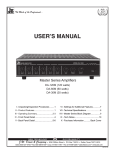
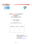
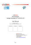
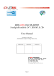
1
PPS1831 Series User Manual (1st Edition June/14/2012) (Version: V1.5) All information is subject to change without notice. Approved by Checked by Prepared by LITEMAX Electronics Inc. 7F‐1, No. 135, Lane 235, Bau‐chiau Rd., Shin‐dian Dist., New Taipei City, 23145 Taiwan. Tel : 886‐2‐8919‐1858 Fax: 886‐2‐8919‐1300 Homepage: http://www.litemax.com/ 1 Record of Revision Version Date Remark 1.1 Mar/30/2012 Initial Release 1.2 Apr/02/2012 Second Version 1.3 Apr/04/2012 Third Version 1.4 May/22/2012 Fourth Version 1.5 June/14/2012 Fifth Version 2 Copyright Notice This document is copyrighted, 2012. All rights are reserved. The original manufacturer reserves the right to make improvements to the product. The information contained in this document is subject to change without notice. This Document contains proprietary information that is protected by copyright. No part of this document may be photocopied, reproduced, translated, or transmitted in any form or by any means without the prior written permission of the original manufacturer. Information provided in this document is intended to be accurate and reliable. However, the original manufacturer assumes no responsibility for its use, nor for any infringements upon the rights of third parties, which may result from its use. The material in this document is for product information only, the original manufacturer reserves the right to make change in the product design without notice to its users. While reasonable efforts have been made in the preparation of this document to assure its accuracy, original manufacturer assumes no liabilities resulting from errors or omissions in this document, or from the use of the information contained herein. 3 Safety and Warranty 1. To disconnect the machine from the electrical power supply, turn off the power switch and remove the power cord plug from the wall socket. The wall socket must be easily accessible and in close proximity to the machine. 2. Read these instructions carefully. Save these instructions for future reference. 3. Make sure the voltage of the power source is correct before connecting the equipment to the power outlet. This product should be operated from the type of power indicated on the marking label. If you are not sure of the type of power available, consult your dealer or local power company. 4. Disconnect this equipment from any AC outlet before cleaning. Do not use liquid or spray detergents for cleaning. Use a damp cloth. 5. Follow all warnings and instructions marked on the product. 6. Do not use this product near water. 7. Do not place this product on an unstable cart, stand, or table. The product may fall, causing serious damage to the product. 8. Slots and openings in the cabinet and the back or bottom are provided for ventilation; to ensure reliable operation of the product and to protect it from overheating. These openings must not be blocked or covered. The openings should never be blocked by placing the product on a bed, sofa, rug, or other similar surface. This product should never be placed near or over a radiator or heat register, or in a built-in installation unless proper ventilation is provided. 9. Do not allow anything to rest on the power cord. Do not locate this product where persons will walk on the cord. 10. Never push objects of any kind into this product through cabinet slots as they may touch dangerous voltage points or short out parts that could result in a fire or electric shock. Never spill liquid of any kind on the product. 11. Never pour any liquid into an opening. This could cause fire or electrical shock. 12. Never open the equipment. For safety reasons, only qualified service personnel should open the equipment. 13. If any of the following situations arises, get the equipment checked by service personnel: a. The power cord or plug is damaged. b. Liquid has penetrated into the equipment. c. The equipment has been exposed to moisture. d. The equipment does not work well, or you cannot get it to work according to the user's manual. e. The equipment has been dropped and damaged. 4 Safety Symbol Description The following safety symbols are the further explanations for your reference. 5 for FCC 15b devices This equipment has been tested and found to comply with the limits for a Class B digital device, pursuant to part 15 of the FCC rules. These limits are designed to provide reasonable protection against harmful interference in a residential installation. This equipment generates, uses and can radiate radio frequency energy and, if not installed and used in accordance with the instructions, may cause harmful interference to radio communications. However, there is no guarantee that interference will not occur in a particular installation. If this equipment does cause harmful interference to radio or television reception, which can be determined by turning the equipment off and on, the user is encouraged to try to correct the interference by one or more of the following measures: -Reorient or relocate the receiving antenna. -Increase the separation between the equipment and receiver. -Connect the equipment into an outlet on a circuit different from that to which the receiver is connected. -Consult the dealer or an experienced radio/TV technician for help. FCC Part 15.21 information for user You are cautioned that changes or modifications not expressly approved by the party responsible for compliance could void your authority to operate the equipment. 6 Legislation RoHS and WEEE Symbol Restriction of the use of certain Hazardous Substances This product uses components that comply with the requirements of the Restriction of the use of certain Hazardous Substances (RoHS) Directive 2002/95/ EC. WEEE 2002/96/EC Waste Electrical and Electronic Equipment Directive on the treatment, collection, recycling and disposal of electric and electronic devices and their components. The crossed dustbin symbol on the device means that it should not be disposed of with other household wastes at the end of its working life. Instead, the device should be taken to the waste collection centers for activation of the treatment, collection, recycling and disposal procedure. To prevent possible harm to the environment or human health from uncontrolled waste disposal, please separate this from other types of wastes and recycle it responsibly to promote the sustainable reuse of material resources. Household users should contact either the retailer where they purchased this product, or their local government office, for details of where and how they can take this item for environmentally safe recycling. Business users should contact their supplier and check the terms and conditions of the purchase contract. This product should not be mixed with other commercial wastes for disposal. This device complies with Part 15 of the FCC Rules. Operation is subject to the following two conditions: (1) this device may not cause harmful interference and (2) this device must accept any interference received, including interference that may cause undesired operation. 7 Acknowledgments Intel®, CoreTM 2 Duo / Celeron are registered trademarks of Intel® Corporation. IBM, PC/AT, PS/2 are trademarks of International Business Machines Corporation. Microsoft® Windows is a registered trademark of Microsoft® Corporation. RTL is a trademark of Realtek Semi-Conductor Co., Ltd. C&T is a trademark of Chips and Technologies, Inc. UMC is a trademark of United Microelectronics Corporation. ITE is a trademark of Integrated Technology Express, Inc. All other product names or trademarks are properties of their respective owners. 8 Table of Contents 1. Item Checklist ........................................................................... 11 2. General Information .................................................................. 13 2.1 Introduction ....................................................................... 13 2.2 Feature .............................................................................. 13 2.3 Specification ...................................................................... 14 2.4 System View ..................................................................... 15 2.5 Product Dimension ............................................................ 17 3. Hardware Installation and Power on/off .................................... 19 3.1 Safety Precautions ............................................................ 19 3.2 HDD Installation ................................................................ 19 3.3 CF Card Installation .......................................................... 21 3.4 Telephone Set Installation ................................................. 22 3.5 MSR Installation ................................................................ 23 3.6 Power on/off Operation ..................................................... 24 4. BIOS Setting ............................................................................. 25 4.1 Main Feature Setup .......................................................... 25 4.2 Advance Chipset Setup ................................................... 25 4.3 Chipset Feature Setup ...................................................... 26 4.4 Boot Devices Setup .......................................................... 26 4.5 Security and Password Setup ........................................... 27 4.6 Save and Exit Option ........................................................ 27 5. Driver Installation ...................................................................... 28 5.1 Wireless LAN Driver Installation........................................ 28 5.2 Card Reader Driver Installation ......................................... 35 9 6. OSD Setting ............................................................................. 44 6.1 Brightness Menu ............................................................... 44 6.2 Audio Menu ....................................................................... 45 6.3 Auto Color Menu ............................................................... 46 6.4 Color Temperature Menu .................................................. 46 6.5 Auto Adjust Menu .............................................................. 47 10 1. Item Checklist Take out the system unit from the carton. Remove the unit by carefully clutching the foam inserts and remove slowly to protect the system. The following contents should be found in the carton: 1 1 1 1 x PPS Series Panel PC x IP Phone Set x CD for User Manual and Driver x AC/DC Adaptor If any of these items should be missing or damaged, please contact your distributor or sales representative immediately. PPS Panel PC Landscape Portrait IP Phone Set 11 AC/DC Power Adaptor CD for User Manual and Touch Driver Packing 12 2.0 General Information 2.1 Introduction The intended use of the Litemax’s “Infotainment System:PPS1831” is made for the security staff and care takers in daycare, hospital and clinical settings for monitoring. PPS1831 is 18.5 inch fanless multi function panel PC, feature power efficient Intel embedded processor and advance long life LED backlight display. With projective capacity multi touch, wireless connectivity, smart card reader and VOIP telephone, PPS1831 provide infotainment solution at the same time. The PPS1831 is a general purpose panel PC with Intel® Atom processor-based computer that is designed to serve as a point of care station, bed side terminal or multi-function computer. It is a PC-based system with 18.5" true color TFT LCD display, Zero Noise solution; integrated multimedia functions make them the perfect platforms to build comprehensive lifestyle computing applications. The PPS1831 includes all the features of a powerful computer into a slim and attractive chassis. The PPS1831 support 2.5” Hard Disk Drive storage function and one Mini-PCI for WLAN expansion. Moreover, they feature flexible I/O ports, such as six USB2.0, one RS-232, two RJ45 for GbE. Convenient operation, Silent, compact, mobility and highly integrated multimedia system let you to focus on healthcare utility, interactive information displays, automation control systems, general desktop usage, multimedia recreation, and other medical requirements. 2.2 Features 18.5” TFT LCD panel PC with 1366x768 resolution LED backlight with low power consumption and constant brightness Landscape & Portrait display mode support Fan-less design provides silent operation, zero noise. Projective capacitive multi-touch screen provides easy and intuitive interactions with application Easily access swappable HDD and CF slot. VOIP telephone provides data and telephone communication onto a common network. CMOS 1.3MP PC camera provides clear photo taken and motion monitoring Smart Card Reader (SCR) and RFID enable electronic record. Wireless LAN and cable LAN provide flexible network connection Bluetooth module provides easily wireless connection IP54 same level facial screen with antibacterial coating provide water proof feature And reduce bacterial buildup. Optional Features: RFID and SCR combo reader. DVB-T and ATSC TV receiver support. IP Phone. 13 2.3 Specification Model Number PPS1831 Description 18.5" Fanless, Intel® ATOM™ D510 1.66GHz Processor, Multi-Function Panel PC Display 18.5" Wide LED Backlight Active Display Area 304.128x228.096 mm Brightness 250 cd/m2 Resolution 1366x768 (HD) Touch Screen Projective Capacitive Multi-Touch Computing Platform Processor Intel® Atom D510 1.66GHz Chip Set Intel® ICH8M Memory SODIMM DDRII 533/667 Memory up to 2GB Ethernet Gigabit Ethernet x 2 Storage 2.5” SATAII HDD drive bay CF to SATAII socket module (optional) External Connectivity X2 RJ-45 Gigabit Ethernet (GbE) X4 USB2.0 X1 COM port RS232 X1 Audio Mic-in, Line-out X1 Smart Card Reader X2 RJ-11 (at right and left side) X1 Four pins DC Input connector X1 DVB-T Antenna connector (IEC type) Internal Connectivity Speaker: 2x2W stereo speaker Internal Microphone: Build in PC Camera: USB Video Class (UVC) compliant camera module Bluetooth: Bluetooth v2.0 + EDR Wireless LAN: WiFi 802.11 b/g OSD: (4 keys and 1 LED) Power on/off button, Power LED, Manual, Volume (+), Volume (-) Optional Features IP Phone: Internet Softphone DVB-T: Digital Video Broadcasting-Terrestrial DAB: Digital Audio Broadcasting RFID: Standard protocol Mifare classic Smart Card Interface: Standard protocol ISO7816-3 ,EMV L1 Power Voltage DC Input: DC 12V Power Adaptor DC 12V Output AC100V~240V (120Watt) Mechanical IP Rating Front IP65 standards when console mounted. 14 Construction Antibacterial plastic housing Mounting VESA75/VESA100 Dimension 447.2x302.9.7x58.98 mm Net Weight 5.4Kg Environmental Operating Temperature 0°C~40°C Storage Temperature -20°C ~ 60°C Operating Humidity 5~95% @ 40°C, non-condensing 2.4 System View 2.4.1 Front View 15 2.4.2 Rear View 2.4.3 Buttom View 16 2.5 Product Dimension 17 18 3.0 Hardware Installation and Power on/off 3.1 Safety Precautions Always completely disconnect the power cord from your board whenever you are working on it. Do not make connections while the power is on, because a sudden rush of power can damage sensitive electronic components. Always ground yourself to remove any static charge before touching the board. Modern electronic devices are very sensitive to static electric charges. Use a grounding wrist strap at all times. Place all electronic components on a static-dissipative surface or in a static-shielded bag when they are not in the chassis 3.2 HDD Installation 3.2.1 Remove the HDD cover screw. 3.2.2 Assembly 2.5” HDD on the HDD carrier metal. 19 3.2.2 Push HDD set into the HDD housing, the connector of HDD toward the housing. 3.2.3 Make sure HDD is connected properly with HDD bay, and then close HDD cover with screw. 20 3.3 CF Card Installation 3.2.1 Remove the HDD cover screw. (CF card is set in the same bay with HDD) 3.2.2 Assembly CF card on the CF carrier metal. 3.2.2 Push CF set into the CF housing, the connector of CF card toward the housing. 3.2.3 Make sure CF card is connected properly with CF bay, and then close HDD cover with screw. 21 3.4 Telephone Set Installation 3.4.1 Tighten the mounting screws on the edge side of phone holder. 3.4.2 Put on the IP Phone and connect the phone cable with bottom side RJ11 connector. 22 3.5 MSR Installation 3.5.1 Tighten the MSR metal set on the edge side of computer. 3.5.2 Assembly MSR module into the metal set. 3.5.3 Connect the MSR cable with edge side USB connector. 23 3.6 Power on/off 3.6.1 Power on the unit, touch the Power on/off symbol for 5 seconds till LED indicator lighting. 3.6.2 If the computer is working on Windows system, power off the unit through OS shut down bottom. Or touch the power on/off symbol for 5 seconds. 24 4.0 BIOS Setting 4.1 Main Features Setup 4.2 Advanced Chipset Setup 25 4.3 Chipset Setup 4.4 Boot Devices Setup 26 4.5 Security and Password Setup 4.6 Save and Exit Option 27 5.0 Driver Installation 5.1 Wire-Less LAN Driver Installation Please found driver file in the driver CD, file name is ”Install Bluewu2.3.04.101224 driver” Please click ”Install” 28 Please click ”Yes” Please click ”OK” 29 Please click ”Next” Please select “I accept the terms in the license agreement”, and then click “Next” 30 Please click “Next” Please click “Install” 31 Please click “Finish” Please click “Next” 32 Please click “Install” Please click “Finish” 33 Please click “Yes”, and then restart the system 34 5.2 Card Reader Driver Installation Please found the Card Reader Driver from CD, file name is “\\Driver\Setp 5 - Option\Castles_SCR & RFID\Win7 driver\Windows7 32bit\setup” Please click “ ok” 35 Please click “Next” Please click ”Install” 36 Please click “OK” Please click “Finish” 37 Setup EZ710 smart card in device manager Please select “Update Driver Software” Please select”Browse my computer for driver software” 38 Please found the Card Reader Driver from CD, file name is “\\Driver\Setp 5 - Option\Castles_SCR & RFID\Win7 driver\release_ez710” Please click “OK” Please click “Next” 39 Please click “Close” Please select “Update Driver Software” 40 Please select”Browse my computer for driver software” Please found the Card Reader Driver from CD, file name is “\\Driver\Setp 5 - Option\Castles_SCR & RFID\Win7 driver\release_ez710” Please click “OK” 41 Please click “Next” Please click “Close” 42 Completed 43 6.0 OSD Setting 6.1 Brightness Menu By pressing the “menu” button, you will see the below picture. Across from timing you will see resolution, frequency, and V-frequency of the panel. Version shows the firmware control version. These cannot be altered by the user. There are 7 sub menus within the OSD user interface: Brightness, Signal Select, Sound, Color, Image, Tools, and Exit. When you press the “menu" button, you enter the “Brightness" sub directory. In this directory, you will see 4 selections: OSD Brightness: press ’’right’’ key Press the “menu” once, to adjust the brightness. Press “left” to dim down the brightness to “0”, press “right” to increase the brightness to “100” Ambient light sensor: Press this Icon for auto dimming. (OPTION) To use this option, the Litemax ambient light sensor needs to have been installed Potentiometer: Navigate to this icon to adjust the VR function. Ambient light sensor with OSD offset: To set minimum brightness level based on ambient light. 44 Press ’’right’’ key Press ’menu’’ once, to adjust minimum luminance to fit your application (OPTION) Contrast: Press “menu” and “right” buttons to adjust the contrast from “0” to “ 100”. To adjust from “100” to “0”, press “menu” and the “left” buttons. Exit: You can exit this sub menu back to normal screen. 6.2 Audio Menu There are 3 options for “Sound” sub page. Audio Volume: Audio volume adjustment. / UnMute/Mute: You can mute the speaker by pressing this option. Exit: back to the beginning menu. 45 6.3 Auto Color Auto Color: By navigating over to the “Auto Color” option, optimal color performance is invoked. SRGB: Windows standard color setting 6.4 Color Temperature Menu Color Temperature: You have 3 options in this selection . Color Temperature User Define: Default is 100 for “R”, “G”, and “B”. Color Tempture_6500K: Warm color scheme 46 Color Tempture_93OOK: Cold color scheme Exit: back to the normal screen. 6.5 Auto Adjust Menu Auto Adjust: Choose this option and the AD5766 will adjust to the optimal horizontal and vertical frequency. You will see “Auto tune….” on the screen for around 3 seconds. Clock: If you are not satisfied with the Auto tune result, you can adjust manually by pressing “Clock”. Using this will make the image wider. Phase: If “double images” appear around the characters, choose “Phase” to remove them.. HPos: You can shift the screen horizontally using this function. Vpos: You can shift the screen vertically using this function. Exit: Back to normal screen. Litemax Electronics Inc. 7F-1, No. 135, Lane 235, Bau-chiau Rd., Shin-dian Dist., New Taipei City, 23145 Taiwan. AlfaNet Computer & Electronic Handle Julius-Faucher-St. 31, 28307 Bremen Germany. 47