1
MINICHEF 2000
TM
Applications 24 & 25
Timer
Applications Guide
Programming & Operating Steps
97
TOTAL
CUSTOMER
SATISFACTION
Watlow Controls
1241 Bundy Blvd.
P.O. Box 5580
Winona, Minnesota U.S.A. 55987-5580
(507) 454-5300, Fax (507) 452-4507
WMC2-XAGN-0005-Rev A
May 1997
ISO 9001
Registered Company
Winona, Minnesota USA
$5.00
Made in the U.S.A.
Table of Contents
Application 24
Automatic Timer . . . . . . . . . . . . . . . . . . . . . . . 1
Application 25
Manual Timer. . . . . . . . . . . . . . . . . . . . . . . . . 7
Ordering Information . . . . . . . . . . . . . . . . . . . 14
© The Watlow MINICHEF 2000™ Timer Applications Guide is copyrighted by Watlow Winona, Inc., May
1997, with all rights reserved. (1011)
24
Application 24
Automatic Timer
Introduction to Application 24 . . . . . . . . . . . . . . 1
Configuration Mode Quick Reference . . . . . . . . . 3
Program Mode Quick Reference . . . . . . . . . . . . 4
Step 7 Design a Faceplate Overlay. . . . . . . . . . . 5
Step 8 Operate the Controller . . . . . . . . . . . . . . 6
Application 24 allows you to program six concurrent timers.
Overview of Key Steps
1. Install the MINICHEF 2000.
2. Wire the controller.
3. Configure the controller.
4. Program the menus.
5. Set the controller security.
6. Set the Real-time Clock.
For instructions on Steps 1, 2, 3, 4, 5 and 6, see the Hardware & Software Setup Guide.
7. Design, manufacture and apply faceplate overlay for end-users. (For a suggested design
to suit this application, see this section. For overlay dimensions and guidelines, see the
Hardware & Software Setup Guide.)
8. Operate the controller. (See this application guide.)
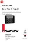
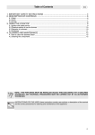
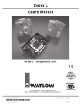
Key Functions in Configuration Mode
MINICHEF 2000
Display five-digit, sevensegment numeric LED
display.
Indicator lights
(1 for each key, 2 for heat
channels).
G
H
A
Edit key (A) Access the
next level of parameters or
values.
Enter key (B) Enter the
value and return to
previous level.
Home key (D) Move to
Operation Mode with a
two-second key press.
C
B
Edit
Up key (C) Move up the
lists.
Enter
D
Home
Escape key (E) Return to
original value when editing
a parameter value.
F
E
Escape
Down key (F) Move down
the lists.
Key Functions in Operation Mode
Your Company Logo
Timer Keys Activate,
acknowledge,shut off and
cancel corresponding
timers.
Time
Time
Time
1
2
3
Time
Time
Time
4
5
6
Timer Key Indicator
Lights
Lit...Timer running
Rapid flash...Done
Summary of Input/Output Functions
Input 1 not used
→
Input 2 not used
→
Event Input 1 not used →
Event Input 2 not used →
Your Company Logo
Time 1
Time 2
Time 3
1
2
3
Time 4
Time 5
Time 6
4
5
6
→
→
→
→
→
Output 1 not used
Output 2 not used
Event Output 1 not used
Event Output 2 not used
Output 5 Audible alarm
Note: For details, see wiring instructions in the Hardware & Software Setup Guide.
2 ■ Watlow M I N I C H E F 2000
Application 24
Configuration Mode Quick Reference
These are the functions, parameters and values included in the Configuration Mode for
this application. You must select Application 24 to access them. For directions, see the
Hardware & Software Setup Guide. The Appendix of that guide includes an explanation
of all parameters and values.
Function
Parameter
Value
{Etype} Equipment-Type
[appl`] Application Number
[a_Loc] Application Number
Security Lock
1 - 28
Yes, No
[SEtUP] Setup
[time] Time Display Format
[Chirp] Key Chirp
[loc``] Menu Security Lock
[Cloc`] Real Time Clock Display
MMM:SS, HH:MM, H:MM:SS
On, Off
Yes, No
Yes, No
[[`diag] WatHelp
Diagnostics
Used for equipment troubleshooting and testing. Not used when programming. See the Hardware
& Software Setup Guide.
Application 24
Your Settings
24
Watlow M I N I C H E F 2000 ■ 3
Program Mode Quick Reference
These are the functions, parameters and values included in the Program Mode for this
application. You must select Application 24 to access them.. For menu programming
directions, see the Hardware & Software Setup Guide. The Appendix of that guide
includes a detailed explanation of all parameters and values.
Function
Parameter
Value
[M`__] Menu Numbers 1 - 6
[TiNe1] Time 1
Run time of menu.
Format varies based
on configuration.
4 ■ Watlow M I N I C H E F 2000
Your Settings
Application 24
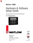
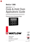
Step 7 Design a Faceplate Overlay
To complete the installation, you must apply a graphic membrane to the front panel of
the controller. The following artwork will help you design and create a membrane for
this application. For more dimensions and guidelines, see the Hardware & Software
Setup Guide.
Suggested End-user Overlay:
Your Company Logo
Time
Time
Time
1
2
3
Time
Time
Time
4
5
6
This Prototyping and Training Membrane Overlay will help you with the configuration and programming steps. To order it, see the Ordering Information
at the back of this guide.
MINICHEF 2000
G
A
Edit
C
Enter
D
E
Home
Application 24
H
B
F
Escape
Watlow M I N I C H E F 2000 ■ 5
Step 8 Operate the Controller
Summary of Key Functions in Operation Mode
Key
Function
A
Time 1
B
Time 2
C
Time 3
D
Time 4
E
Time 5
F
Time 6
Startup
Apply power to the controller.
[`idle] will appear on the display.
If the Real-time Clock Display option is installed and [Setup] / [Cloc`] is set to
[``yes], the time of day will appear on the display.
Run a Timer
1. With [`idle] on the display, press the key for the timer that you want to run. If a
timer is currently running you may activate another timer by pressing the key for
that timer. Any combination of timers may be running simultaneously. When the
controller is running multiple timers the timer with shortest countdown time will be
displayed.
2. When a timer has completed [``end] will appear on the display, the timer key indicator light will flash rapidly, and an alarm will sound until the timer key is pressed
to acknowledge and shut off that timer.
3. To run another timer repeat steps 1 and 2.
Note: The controller will not respond if you select an invalid timer (one for which Time 1 is set to 0).
Cancel a Timer
Canceling a timer stops that timer only. The other running timers will continue to run.
•
Press the active timer key for 2 seconds.
Restart Timer
Press the key(s) for the timer(s) you want to run at any time.
Errors
The controller will alert you to errors if they occur. Errors are critical problems that
shut down the unit. If an error occurs, an error message will appear on the display. You
should switch off the power and call for service.
See the Appendix in the Hardware & Software Setup Guide for a summary of errors.
6 ■ Watlow M I N I C H E F 2000
Application 24
25
Application 25
Manual Timer
Introduction to Application 25 . . . . . . . . . . . . . . 7
Configuration Mode Quick Reference . . . . . . . . . 9
Step 7 Design a Faceplate Overlay . . . . . . . . . . 10
Step 8 Operate the Controller . . . . . . . . . . . . . 11
Manual Timer
Application 25 is a timer, controlling no temperature zones, and controlling one timer.
Overview of Key Steps
1. Install the MINICHEF 2000.
2. Wire the controller.
3. Configure the controller.
4. Program the menu.
5. Set the controller security.
6. Set the Real-time Clock.
For instructions on Steps 1, 2, 3, 4, 5 and 6, see the Hardware & Software Setup Guide.
7. Design, manufacture and apply faceplate overlay for end-users. (For a suggested
design to suit this application, see this section. For overlay dimensions and guidelines, see the Hardware & Software Setup Guide.)
8. Operate the controller. (See this application guide.)
Key Functions in Configuration Mode
MINICHEF 2000
Display five-digit, sevensegment numeric LED
display.
Indicator lights
(1 for each key, 2 for heat
channels).
G
H
A
Edit key (A) Access the
next level of parameters or
values.
Enter key (B) Enter the
value and return to
previous level.
Home key (D) Move to
Operation Mode with a
two-second key press.
C
B
Edit
Up key (C) Move up the
lists.
Enter
D
Home
Escape key (E) Return to
original value when editing
a parameter value.
F
E
Escape
Down key (F) Move down
the lists.
Key Functions in Operation Mode
Your Company Logo
Increment
Time Indicator Light Will
flash rapidly if editing the
parameter during menu
operation.
Not Used
Start/Stop
Activate or cancel active
menu.
1
2
3
Time
Up
4
5
6
Pause
Start/Stop
Down
Decrement
Time Set time.
Pause Pause active
menu.
Start/Stop Indicator Light
Rapid flash...Timer paused
Lit...Timer running
Summary of Input/Output Functions
Input 1 not used
→
Input 2 not used
→
Event Input 1 not used
→
Event Input 2 not used
→
Your Company Logo
Heat
1
4
Pause
→Output 2 not used
Heat
2
Time
5
Start/Stop
→Output 1 not used
3
Up
6
Down
→Event Output 1 not used
→Event Output 2 Timer Output
→Output 5 Audible Alarm
Note: For details, see wiring instructions in the Hardware & Software Setup Guide.
8 ■ Watlow M I N I C H E F 2000
Application 25
Configuration Mode Quick Reference
These are the functions, parameters and values included in the Configuration Mode for
this application. You must select Application 25 to access them. For directions, see the
Hardware & Software Setup Guide. The Appendix of that guide includes an explanation
of all parameters and values.
Function
Parameter
Value
{Etype} Equipment-Type
[appl`] Application Number
[a_Loc] Application Number
Security Lock
[t`OUt] Timer Output
1 - 28
Yes, No
[SEtUP] Setup
[time] Time Display Format
[Chirp] Key Chirp
[Cloc`] Real Time Clock Display
MMM:SS, HH:MM, H:MM:SS
On, Off
Yes, No
[[`diag] WatHelp
Diagnostics
Used for equipment troubleshooting and testing. Not used when programming. See the Hardware
& Software Setup Guide.
Application 25
Your Settings
25
Yes, No
Watlow M I N I C H E F 2000 ■ 9
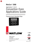
Step 7 Design a Faceplate Overlay
To complete the installation, you must apply a graphic membrane to the front panel of
the controller. The following artwork will help you design and create a membrane for
this application. For more dimensions and guidelines, see the Hardware & Software
Setup Guide.
Suggested End-user Overlay:
Your Company Logo
2
1
3
Time
4
Up
6
5
Pause
Start/Stop
Down
This Prototyping and Training Membrane Overlay will help you with the configuration and programming steps. To order it, see the Ordering Information
at the back of this guide.
MINICHEF 2000
G
A
B
Edit
D
Home
10 ■ Watlow M I N I C H E F 2000
H
C
Enter
E
F
Escape
Application 25
Step 8 Operate the Controller
Summary of Key Functions in Operation Mode
Key
Function
A
Not Used
B
Time
C
Increment
D
Pause
E
Start/Stop
F
Decrement
Startup
Apply power to the controller.
[`idle] will appear on the display.
If the Real Time Clock Display option is installed and [Setup] / [Cloc`] is set to
[``yes], the time of day will appear on the display.
Set the Timer
1. Press the Time key [TiNe1] and then the time value will appear on the display.
2. Press the Up-arrow or Down-arrow key until the value you want appears on the display.
3. Press the Time key again.
The timer has been set.
[`idle] will appear on the display.
Five Second Timeout
When using the Up-arrow or Down-arrow keys to change a value, if you do not press
any key for 5 seconds, the timer will automatically be set to the last value on the display and return to [`idle].
Run the Timer
1. Set the timer as shown above in “Set the Timer”.
2. To run the timer settings, press the Start/Stop key. The timer will countdown. When
the timer is running the Start/Stop key indicator light will be solid on. While the
timer is running, its time can be adjusted by pressing the Time key [TiNe1] and
using the Up-arrow or Down-arrow keys to adjust its value, in five-second intervals.
The Time key indicator light will flash while adjustments are being made. Changing
the value of the Time while the timer is running will not change the settings of the
timer as set in “Set the Timer”.
Application 25
Watlow M I N I C H E F 2000 ■ 11
3
When the timer has completed [``end] will appear on the display, the Start/Stop
key indicator light will flash rapidly, and an alarm will sound until the Start/Stop
key is pressed to acknowledge and shut off the timer.
4. To run the timer again repeat steps 1 thru 3.
Note: The controller will not respond if Time is set to 0.
Pause a Menu
While the timer is counting down you can pause it by pressing the Pause key. The
Pause key indicator light will flash rapidly until you press it again to resume the countdown.
Cancel a Menu
To cancel the active menu, press and hold the Start/Stop key for approximately 2 seconds.
Event Outputs
When [etype] / [t`OUt] in the Configuration Mode is set to [``yes], Event Output 2
is on during the countdown of the timer.
Errors
The controller will alert you to errors if they occur. Errors are critical problems that
shut down the unit. If an error occurs, an error message will appear on the display. You
should switch off the power and call for service.
See the Appendix in the Hardware & Software Setup Guide for a summary of errors.
12 ■ Watlow M I N I C H E F 2000
Application 25
Specifications (1032)
Control Mode
1
• Single and dual heat channels, PID or on/off.
• Microprocessor-based, programmable, reverse-acting
control outputs.
• User-selectable embedded application software defines
operation of display, keys, inputs, outputs, timing action.
• One-step auto-tuning, WatHelp diagnostics, WatCurve
temperature compensation.
Agency
• CE approved:
89/336/EEC Electromagnetic Compatibility Directive
-EN 50081-1: Emissions
-EN 50082-1: Immunity
73/23/EEC Low-Voltage Directive
-EN 60730-1 and EN 60730-2-9: Safety
• NSF Listed, Criteria 2.5
• AGA: UL tested to AGA standard Z21.23, UL File
#E43684.
• UL and C-UL recognized, UL 197, 873, 991 and CSA
standard C22.2-24, File # E43684.
Operator Interface
• Membrane overlay, contamination and water resistant,
(supplied by customer).
• LED display, 5-digit, 0.56 in high, red.
• Displays times, temperatures, user prompts and
diagnostic codes.
• User-selectable time and temperature display formats.
• Temperature display formats—˚F or ˚C.
• Time display formats—H:MM:SS, HH:MM, or MMM:SS.
• 8 discrete indicator LEDs, red.
• 6 tactile feedback keys.
• Menu-driven operation and manual modes available.
• WatHelp diagnostics.
• Real-time clock option displays time of day.
Accuracy
2
• Calibration accuracy and sensor conformity : ± 2.0°F
for Type J thermocouple and RTD, ± 0.35% of span for
Type K and E thermocouples, ±1 LSD, 77°F ± 5°F
ambient and rated line voltage of ±10%.
• Accuracy span: 1000°F (540°C) minimum.
• Temperature stability: ± 0.15˚F/ ˚F (0.15˚C/˚C) change
in ambient typical.
Sensors / Inputs
• Contact inputs, TTL compatible with internal pull-up
resistor, two available.
3
• Thermocouple, software selectable Type J, K or E,
32 to 1200°F. (Dual-channel applications require at
least one ungrounded thermocouple).
3
• RTD, 2- or 3-wire, platinum, 100, 500, 1000Ω, at 0°C,
software selectable DIN or JIS curves, 0 to 1200°F
(3-wire will function as 2-wire).
• Input A / D resolution: 15 bit.
Output Options
• Solid-state relay, 0.4A, with or without contact suppression.
• Switched dc signal, 4.5V to 5.25V, 30mA maximum
output, minimum load resistance > 150Ω, non-isolated.
Specifications
Audible Output Options
• Switched dc signal, 4.5V to 5.25V, 30mA maximum
output, minimum load resistance > 150Ω, non-isolated.
• Internal audible alarm, 75dB at 10 cm.
Connectors
4
• Sensor Input Terminal Strip : RIACON, 6-position,
quick-connect.
4
• Power Supply & Input / Output Terminal : AMP,
15-position, quick-connect.
Power / Line Voltage
• 20.4 to 26.4VÅ (ac), 47 to 63Hz.
• 15VA maximum.
• For CE applications, input power must be limited to
15W external to the control.
• Program retention upon power failure via non-volatile
memory.
• Battery / real-time clock option: 6-year lithium battery,
provides power backup upon power failure, operation
resumption after power recovery, ability to display time
of day.
Operating Environment
• 32 to 176°F (0 to 80°C), 0 to 90% RH, non-condensing.
Storage Temperature
• -40 to 176°F (-40 to 80°C).
Mechanical
• Case: polycarbonate Lexan with adjustable mounting
collar (vertical or horizontal orientation), designed for
mounting on 16-, 18-, 20- and 22-gauge panels.
• Internal panel mounting requires a specified panel
cutout and four #6-32 studs or equivalent.
• Overall width x height x depth: horizontal - 4.13 in x
3.25 in x 2.00 in; vertical - 3.25 in x 4.13 in x 2.00 in
(Assumes mating connectors are attached. Does not
include wire bundle space requirements.).
• Vibration: 2g, 10 to 150Hz, applied in any one of three
axes.
• Weight: 6.50oz maximum.
Program Storage
• All non-embedded user and factory programs are
stored in non-volatile memory. Can be changed by
reprogramming.
Sample/Update Rates
• 1 input: 4Hz.
• 2 inputs: 4Hz.
• PID: 1Hz.
• Control outputs: 100Hz.
• Display: 10Hz.
1
The MINICHEF 2000 controller is to be used in systems with an
external high temperature limiting device.
2
Thermocouple lead resistance of 200Ω causes < 1°C error. RTD, 22
gauge wire will not contribute more than 0.086°F error / ft.
3
Dual channel applications require either two thermocouple sensors or two identical RTD sensor types.
For mating connector information, see Ordering Information
Accessory section.
4
5
Certified for thermometer accuracy (oven and hot food holding
applications from 32°F to 60°F) when used with RTD or type J thermo
couple probes.
Watlow M I N I C H E F 2000 ■ 13
Ordering Information
(1033)
F 2 HA- _ _ _ 1 - _ _AA
MINICHEF™ 2000
Cooking controller with numerous food
equipment application software sets,
single and dual channel on/off or PID
temperature regulation, timer and
machine-function control, microprocessorbased, programmable, auto-tuning,
WatCurve, WatHelp diagnostics,
24VÅ (ac) power input, agency approved,
flush mounted (membrane faceplate
supplied by customer).
Inputs
1 = Dual thermocouple, Type J, K or E
2 = Dual RTD, platinum, 100Ω, curve
selectable
3 = Dual RTD, platinum, 500Ω, curve
selectable
4 = Dual RTD, platinum, 1000Ω, curve
selectable
(Note: All models include two event inputs,
switched dc logic signal, non-isolated.)
Output Number 1
1 = Switched dc, 5V nominal, 30mA,
non-isolated
2 = Solid-state relay, Form A, 0.4A,
without RC suppression
3 = Solid-state relay, Form A, 0.4A,
with RC suppression
Output Number 2
1 = Switched dc, 5V nominal, 30mA,
non-isolated
2 = Solid-state relay, Form A, 0.4A,
without RC suppression
3 = Solid-state relay, Form A, 0.4A,
with RC suppression
Event Outputs 1 and 2
1 = 2 event outputs, switched dc, 5V nominal,
30mA, non-isolated
Battery and Real-time Clock
0 = None
1 = Includes battery and real-time clock
Audible Alarm
0 = Alarm signal available at connector,
switched dc, 5V nominal, 30mA, non-isolated
1 = Internal alarm included
Software
AA = Standard Food Equipment Application
Software Set
XX = Custom Set-up parameters or Made-To-Order
custom software. Consult your local Watlow
Sales Engineer. Code number assigned by factory.
14 ■ Watlow M I N I C H E F 2000
Ordering Information
Ordering Information: Part Numbers & Accessories
MINICHEF 2000 Accessories
MINICHEF 2000 Documentation
0836-0442-0000
WMC2-XUGN-0000
A001-0298-0000
0238-0679-0000
0830-0479-0000
A001-0249-0001
A001-0249-0002
Sensor Input Mating Connector,
(RIACON #31007106), 6-position,
quick-connect terminal, screw
connection for 28-14 AWG wires,
tighten to 7 in/lb
Power Supply and I / O Mating
Connector Kit. Includes:
– 1 AMP #1-640523-0, 15-position,
quick-connect terminal
– 15 AMP #641300-1 crimp pins
Prototyping & Training Membrane
Overlay, adhesive-backed,
4.75 in x 4.75 in
Prototyping EPROM Extraction Tool,
AMP #821980-1
120VÅ to 24VÅ (ac), stepdown
transformer, class 2, quick-connect
terminals included
208 / 240 VÅ to 24 VÅ (ac), stepdown transformer, class 2, quickconnect terminals included
WMC2-XADN-0000
WMC2-XTDN-0000
WMC2-XSGN-0000
WMC2-XAGN-0001
WMC2-XAGN-0002
WMC2-XAGN-0003
WMC2-XAGN-0004
WMC2-XAGN-0005
WMC2-XAGN-0006
WMC2-XAGN-0007
The Complete MINICHEF
2000 User Guide
The Complete MINICHEF
2000 User Guide on CD
MINICHEF 2000 Tutorial
Disk
Hardware & Software
Setup Guide
Cook-&-Hold Oven
Application Guide
Convection Oven
Application Guide
Deepfat Fryer Application
Guide
Griddle Application Guide
Timer Application Guide
Shelf-Timer Application
Guide
Rotisserie Oven
Application Guide
Recommended Sources of Supply
for Miscellaneous Items
DURA-TECH, Inc.
LaCrosse, WI
(608) 781-2570
•Custom Membrane Faceplates
AMP, Inc.
Harrisburg, PA
1-800-522-6752
•Prototyping EPROM Extraction
Tool Part No. 821980-1
•Pin Crimping Hand Tools
Part No. 90325-1 or 58514-1
•Pin Extraction Hand Tool
Part No. 455822-2
RIA Electronic, Inc.
Eatontown, NJ
(908) 389-1300
•RIACON Connectors
Ordering Information
Watlow M I N I C H E F 2000 ■ 15
Watlow Controls
Watlow Controls is a division of Watlow Electric Mfg. Co., St. Louis, Missouri, a manufacturer of industrial electric heating products since 1922. Watlow begins with a full set
of specifications and completes an industrial product that is manufactured totally inhouse, in the U.S.A. Watlow products include electric heaters, sensors, controls and
switching devices. The Winona operation has been designing solid state electronic control devices since 1962, and has earned the reputation as an excellent supplier to original equipment manufacturers. These OEMs depend upon Watlow Controls to provide
compatibly engineered controls that they can incorporate into their products with confidence. Watlow Controls resides in a 100,000-square-foot marketing, engineering and
manufacturing facility in Winona, Minnesota.
Technical Assistance
If you encounter a problem with your Watlow controller, refer to the Troubleshooting
Chart in this guide. Also review all of your configuration information for each step of
the setup to verify that your selections are consistent with your applications.
If the problem persists after checking all the steps, you can get technical assistance by
calling Watlow Controls at (507) 454-5300, between 7 a.m. and 5 p.m. CST, and asking
for an applications engineer. When you call have the following information on hand: the
controller’s part number, date code, serial number, software revision number, and application number. Much of this information is available on the controller case. All of this
information is also available via the MINICHEF 2000 main display by accessing the
WatHelp Diagnostics Function under [`diag] in the Configuration Mode.
We Value Your Feedback
Your comments and suggestions on this manual are welcome. Please send them to,
Technical Writer, Watlow Controls, 1241 Bundy Blvd., P.O. Box 5580, Winona, MN
55987-5580 or call (507) 454-5300 or fax (507) 452-4507.
Contact
•
•
•
•
•
Phone: (507) 454-5300.
Fax: (507) 452-4507.
For technical support, ask for an Applications Engineer.
To place an order, ask for Customer Service.
To discuss a custom option, ask for the MINICHEF 2000 Product Manager.
Warranty
The MINICHEF 2000 is warranted to be free of defects in material and workmanship for
36 months after delivery to the first purchaser for use, providing that the unit has not
been misapplied. Since Watlow has no control over its use, or misuse, we cannot guarantee against failure. Watlow's obligations hereunder, at Watlow's option, are limited to
replacement or refund of purchase price of a unit which upon examination proves to be
defective within the warranty period. This warranty does not apply to damage resulting
from transportation, alteration, misuse, or abuse.
Returns
• Call or fax Customer Service for a Return Material Authorization (RMA) number
before returning a control.
• Put the RMA number on the shipping label, and also on a description of the problem.
• 20% of net price restocking charge applies to all standard units returned to stock.
Note: All documentation of the MINICHEF 2000 is subject to change without notice.
16 ■ Watlow M I N I C H E F 2000
Warranty and Returns
Watlow MINICHEF™ 2000 Timer Applications Guide
Watlow Controls, 1241 Bundy Blvd., P.O. Box 5580, Winona, MN U.S.A. 55987-5580 Phone: (507) 454-5300, Fax: (507) 452-4507


![Descargar - index [revista.cnic.edu.cu]](http://vs1.manualzilla.com/store/data/006273898_1-89efab09a622fdfc6ec934b030e2e15f-150x150.png)