1
MINICHEF 2000
TM
Hardware & Software
Setup Guide
For All Applications
97
TOTAL
CUSTOMER
SATISFACTION
Watlow Controls
1241 Bundy Blvd.
P.O. Box 5580
Winona, Minnesota U.S.A. 55987-5580
(507) 454-5300, Fax (507) 452-4507
WMC2-XSGN-0000-Rev A
May 1997
ISO 9001
Registered Company
Winona, Minnesota USA
$15.00
Made in the U.S.A.
WATLOW MINICHEF™ 2000
All Applications
Hardware & Software
Setup Guide
Introduction . . . . . . . . . . . . . . . . . . . . . . . . .3
Application Selection Table . . . . . . . . . . . . . . .4
Overview of Key Steps . . . . . . . . . . . . . . . . . .5
General Description . . . . . . . . . . . . . . . . . . . .6
Step 1 Installation . . . . . . . . . . . . . . . . . . . . .8
Step 2 Wiring . . . . . . . . . . . . . . . . . . . . . . .12
Step 3 Configure the Controller . . . . . . . . . . .17
Overview of Configuration and Programming
Controller Front Panel Layout
Software Structure
Navigation
Configuration Mode Quick Reference
Procedure
Step 4 Program the Menus . . . . . . . . . . . . . .25
Program Mode Quick Reference
Procedure
Step 5 Set Security . . . . . . . . . . . . . . . . . . .29
Step 6 Set Real-time Clock . . . . . . . . . . . . . .30
Step 7 Design Membrane Overlay . . . . . . . . . .31
Overlay Design Guidelines
(For Step 8, Operation, see individual application
guides)
Appendix . . . . . . . . . . . . . . . . . . . . . . . . . .33
Troubleshooting Chart
Definitions of Functions, Parameters, Values
Definitions of Temperature Alarms
Definitions of Errors
Glossary of Terms
Specifications
Ordering Information
Warranty and Returns Policy
Index
Declaration of Conformity
Application Number Guide
Cook-&-Hold Ovens
Application 1 . . . . . . . . Automatic Cook-&-Hold Oven with Meat Probe Option
Application 2 . . . . . . . . Automatic Cook-&-Hold Oven with Meat Probe Option
Application 3 . . . . . . . . Automatic Cook-&-Hold Oven
Application 4 . . . . . . . . Automatic Cook-&-Hold Oven
Application 5 . . . . . . . . Manual Cook-&-Hold Oven with Meat Probe Option
Application 6 . . . . . . . . Manual Cook-&-Hold Oven
Convection Ovens
Application 7 . . . . . . . . Automatic Convection Oven
Application 8 . . . . . . . . Automatic Convection Oven
Application 9 . . . . . . . . Manual Convection Oven
Deepfat Fryers
Application 10 . . . . . . . Automatic Deepfat Fryer with Autolift Control
Application 11 . . . . . . . Automatic Deepfat Fryer with Autolift Control
Application 12 . . . . . . . Manual Deepfat Fryer with Autolift Control
Application 13 . . . . . . . Pressurized Automatic Deepfat Fryer
Application 14 . . . . . . . Pressurized Automatic Deepfat Fryer
Application 15 . . . . . . . Pressurized Manual Deepfat Fryer
Application 16 . . . . . . . Automatic Deepfat Fryer
Application 17 . . . . . . . Automatic Deepfat Fryer
Application 18 . . . . . . . Automatic Deepfat Fryer
Application 19 . . . . . . . Manual Deepfat Fryer
Griddles
Application 20 . . . . . . . Automatic Clam Shell Griddle
Application 21 . . . . . . . Manual Clam Shell Griddle
Application 22 . . . . . . . Automatic One-Sided Griddle
Application 23 . . . . . . . Manual One-Sided Griddle
Timers
Application 24 . . . . . . . Automatic Timer
Application 25 . . . . . . . Manual Timer
Shelf Timer
Application 26 . . . . . . . Shelf Timer
Rotisserie Ovens
Application 27 . . . . . . . Manual and Automatic Rotisserie Oven with Meat Probe Option
Application 28 . . . . . . . Manual Rotisserie Oven with Meat Probe Option
2 ■ Watlow M I N I C H E F 2000
Hardware & Software Setup Guide
Introduction
Welcome to the MINICHEF 2000™
The MINICHEF 2000 is a configurable, time/temperature and machine function controller
that is preprogrammed for dozens of cooking applications. Its compact size and optional
horizontal/vertical orientation facilitates streamlined equipment design. It withstands
rigorous application environment conditions, with an 80ºC ambient rating and superior
EMI/RFI immunity. It is also backed by Watlow’s exclusive three-year warranty.
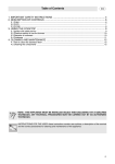
Each unit is equipped to offer:
•
two temperature sensor inputs
•
two event inputs (for machine control)
•
two heat control outputs
•
two event outputs (for machine control)
•
one audible alarm output
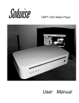
(See diagram below.)
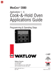
Depending on the application software you select, some or all of the inputs or outputs
are used. See the Application Selection Table that follows.
4 Inputs
5 Outputs
Input 1
Thermocouple or RTD
Output 1
Switched DC or Solid-state Relay
Input 2
Thermocouple or RTD
Event Input 1
G
Output 2
Switched DC or Solid-state Relay
H
A
B
C
D
E
F
Event Input 2
Output 3
Event Output 1
Output 4
Event Output 2
Output 5
Audible Alarm Output
Figure 3 — Inputs and outputs.
Hardware & Software Setup Guide
Watlow M I N I C H E F 2000 ■ 3
Introduction
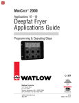
MINICHEF™ 2000 Application Software Selection Table
To select the application software that best suits your equipment and purpose, first
locate the type of equipment in the left column, then check the other columns for features and options you need. The application number is on the right (Appl#). Make a
note of the application number. You will be using this number later when programming
your controller. The guide for each application contains specific configuration and programming parameters, and operating instructions. Note that the use of the software
below is not limited to the equipment types listed in the first column.
Intended Equipment Type
(May also apply to other apps)
COOK & HOLD OVENS
Operation
Mode
No. of
Menus
Heat Output Timed Meat
Channels Zones Probe
Fan
Speeds
Steps
Appl
#
Auto
Auto
Auto
Auto
Manual
Manual
6
17
6
20
N/A
N/A
Single
Single
Single
Single
Single
Single
1
1
1
1
1
1
Yes
Yes
No
No
Yes
No
1
1
1
1
or 2
2
or 2
2
or 2
2
or 2
2
No
1 or 2
No
1 or 2
1
2
3
4
5
6
Auto
Auto
Manual
6
15
N/A
Single
Single
Single
1
1
1
No
No
No
1 or 2
4
1 or 2
4
1 or 2 1 or 2
7
8
9
Auto
Auto
Manual
Auto
Auto
Manual
Auto
Auto
Auto
Manual
4
40
N/A
6
40
N/A
6
2/4
40
N/A
Single
Single
Single
Single
Single
Single
Single
Single
Single
Single
1
1
1
1
1
1
1
2
1
1
No
No
No
No
No
No
No
No
No
No
No
No
No
No
No
No
No
No
No
No
1
1
1
1
1
1
1
1
1
1
10
11
12
13
14
15
16
17
18
19
Auto
Manual
Auto
Manual
6
N/A
6
N/A
Dual
Dual
Single
Single
1
1
1
1
No
No
No
No
No
No
No
No
1
1
1
1
20
21
22
23
Auto
Manual
Auto
6
N/A
6
N/A
N/A
Single
6
1
6
No
No
No
No
No
No
1
1
1
24
25
26
Manual & Auto 30
Manual
N/A
Single
Single
1
1
Yes
Yes
Notes
CONVECTION OVENS
DEEPFAT FRYERS
Pressurized
Pressurized
Pressurized
GRIDDLES
Clam Shell
Clam Shell
One-sided
One-sided
TIMERS
No temp. control
No temp. control
SHELF TIMER
ROTISSERIE OVENS
Yes (1) 1 or 2
Yes (1) 1 or 2
27
28
Table 4 — Application selection table.
4 ■ Watlow M I N I C H E F 2000
Hardware & Software Setup Guide
Introduction
Overview of Key Steps, from Installation through Operation:
1
Install the controller
•
2
Wire the controller
•
3
Use the panel knock-out pattern guidelines in this guide.
Use the connector/wiring information in this guide.
Configure the controller
•
After applying power, use the Configuration Mode to enter the equipment
Application Number (from the MINICHEF 2000 Software Selection table), set up the
controller and access the thermal optimization functions.
•
Use the space provided to record your values for future reference.
•
Set the Application Number Security Lock, if necessary, to prohibit end users from
changing Application Number.
•
To speed configuration, you may want to use the Prototyping/Training Overlay
(available separately, see Ordering Information in this guide).
Note: Always select and enter the application number first. The parameters that follow are based on it. See instructions in this Hardware & Software Setup Guide.
4
5
Program the menus (automatic menu applications only)
•
Use the Program Mode to program automatic menus for the chosen application. See
instructions in this guide.
•
Use the space provided to record your values for future reference.
•
To ease menu programming, you may want to use the Prototyping/Training Overlay
(available separately, see Ordering Information in this guide).
Set menu security (automatic menu applications only)
•
6
Set up menu security, if necessary, to prohibit end users from changing values.
(Because the controller defaults to no security, the end user may be able to access
the Program Mode to change parameter values based on menu.) See instructions in
this guide.
Set Real-time Clock
This applies only to controllers purchased with the Real-time Clock option. It allows you
to see the time of day instead of “idle” on the display.
7
8
Design faceplate overlay
•
Use the Overlay Design Guidelines in this guide to design, manufacture and apply a
membrane overlay for the controller faceplate. This custom-designed overlay
becomes the end-user interface.
•
For overlay designs to suit specific applications, see the suggestions in each application guide.
Operate the MINICHEF 2000
•
Use the Operation Mode to run the installed controller. This is the default mode.
Operation instructions are included in each application guide.
Hardware & Software Setup Guide
Watlow M I N I C H E F 2000 ■ 5
General Description
General Description
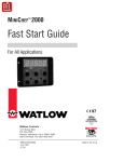
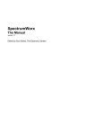
Getting to know your MINICHEF™ 2000
Front view
Back view
Shown with mating connector terminals installed.
Mating connectors and terminals are purchased
separately.
2.00 in.
IIIIIIIIII IIIIIII IIIIIIIIII IIIIIIII
OPER. RANGE 0-80 DEG C
2=OC+
3=OC35=OC+
6=OC48=EI1+
9=ALARM
G
H
A
B
C
D
E
F
11=EI2+
12=EI113=L2 24V
14=L1 24V
15=EI2-
3.00 in.
NSF
c
13
10
7
4
1
14
11
8
5
2
15
12
9
6
3
WATLOW
CONTROLS
INPUT#1 NOT INPUT#2 NOT
TC+ TC- USED TC+ TC- USED
3.00 in.
Figure 6a — Front and back view.
3.25 in.
4.13 in.
Mounting collar
Figure 6b — Mounting collar.
Dimensions:
Overall width x height x depth (Includes MINICHEF 2000 with mounting collar and space
required for mating connectors. Does not include wire bundle space requirements):
4.13 in x 3.25 in x 2.00 in (with collar mounted in horizontal position)
3.25 in x 4.13 in x 2.00 in (with collar mounted in vertical position)
6 ■ Watlow M I N I C H E F 2000
Hardware & Software Setup Guide
General Descrip tion
Mating Connectors (purchased as an accessory — not included):
See Accessories ordering information about the following mating connectors:
Sensor Input Mating Connector: RIA Electronic Inc. RIACON #31007106, 6-position,
quick-connect terminal, screw connection for 28-14 AWG wires, tighten to 7 in/lb.
Power Supply and Input/Output Mating Connector Kit: Kit includes: one AMP #1640523-0 quick-connect terminal and fifteen AMP #641300-1 crimp pins.
Sensor Input Mating Connector
Power Supply and Input/Output Mating Connector
Figure 7a — Mating connectors.
Note: Position mating connector with beveled edges at the top. They are not visible from the front.
Label Information:
Main Label
Part number
Date Code
Serial number
HA
xxx1-xxxx
xxxxx
DATECODE:XXXXX,
S/N:XXXXX
xxxxx
OPER. RANGE 0-80 DEG C
2=OC+
3=OC3-
Pin designations
5=OC+
6=OC4-
Agency marks
NSF
C
8=EI1+
9=ALARM
11=EI2+
12=EI113=L2 24V
14=L1 24V
15=EI2-
Sensor input label
If RTD sensors are specified:
INPUT 1
S1
S2
S3
S1
INPUT 2
S2
S3
1 2 3 4 5 6
If thermocouples are specified:
INPUT 1
TC+
TC—
N
O
T
U
S
E
D
INPUT 2
TC+ TC—
1 2 3 4 5
N
O
T
U
S
E
D
6
Figure 7b — Labels.
Hardware & Software Setup Guide
Watlow M I N I C H E F 2000 ■ 7
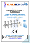
Step 1 Install the Controller
Step 1 Install the Controller
•
Select sheet metal (16-, 18-, 20- or 22- gauge panel).
•
For panel knock-out patterns, see subsequent pages of this guide.
•
Use #6-32 mounting studs x 0.50” length minimum, either pressed or welded.
•
Install the unit with either a horizontal or vertical mounting collar position.
•
Install mating connectors to unit.
Note: This device should be used in systems that incorporate a separate high limit device for safety.
Mounting Collar
in horizontal position
MINICHEF 2000 Controller
Panel showing recommended knock-out pattern
Figure 8 — Mounting the MINICHEF 2000.
8 ■ Watlow M I N I C H E F 2000
Hardware & Software Setup Guide
Step 1 Install the Controller
in
.
in
.
1.
87
5
1.
40
5
in
.
1.
00
0
in
.
0.
50
0
in
.
0.
00
0
in
.
0.
50
0
in
.
1.
00
0
in
.
1.
40
5
1.
87
5
in
.
Panel Knock-out Pattern for a Mounting Collar in a Horizontal Position
2.535 in.
2.125 in.
.875 in. ref
1.660 in.
1.530 in.
1.250 in.
ø0.53 in. (6)
0.875 in.
ø0.135 in. (10)
0.375 in.
0.125 in.
0.000 in.
#6-32 stud (4)
minimum recommended
length 0.50 in.
0.250 in.
1.
1.
37
37
5
5
in
in
.
.
C/L
.
1.
87
5
in
1.
33
8
0
00
1.
in
.
.
in
.
0.
50
0
in
.
0.
00
0
in
.
0.
50
0
in
.
in
0
00
1.
7
33
1.
1.
87
5
in
in
.
.
Figure 9a — Pattern for horizontal panel 16- or 18-gauge thick.
2.462 in.
2.125 in.
.800 in. ref
1.662 in.
1.530 in.
1.250 in.
ø0.53 in. (6)
0.875 in.
ø0.135 in. (8)
0.375 in.
0.125 in.
0.000 in.
#6-32 stud (4)
minimum recommended
length 0.50 in.
C/L
Figure 9b — Pattern for horizontal panel 20- or 22-gauge thick.
Hardware & Software Setup Guide
Watlow M I N I C H E F 2000 ■ 9
Step 1 Install the Controller
.
5
in
.
40
1.
00
0
in
.
1.
0.
50
0
in
.
00
0
in
.
0.
0.
50
0
in
.
in
0
00
1.
1.
40
5
in
.
Panel Knock-out Pattern for a Mounting Collar in a Vertical Position
3.000 in.
2.535 in.
.875 in. ref
1.660 in.
1.530 in.
1.250 in.
ø0.53 in. (6)
0.875 in.
ø0.135 in. (10)
0.375 in.
0.000 in.
0.250 in.
0.750 in.
.
.
in
in
1.
37
5
0
00
#6-32 stud (4)
minimum recommended
length 0.50 in.
1.
0
00
1.
1.
37
5
in
in
.
.
C/L
Figure 10 — Pattern for vertical panel 16- or 18-gauge thick.
10 ■ Watlow M I N I C H E F 2000
Hardware & Software Setup Guide
in
.
in
.
33
8
1.
1.
00
0
in
.
0.
50
0
in
.
0.
00
0
in
.
0.
50
0
in
.
00
0
1.
1.
33
7
in
.
Step 1 Install the Controller
3.000 in.
2.462 in.
.800 in. ref
1.662 in.
1.530 in.
1.250 in.
ø0.53 in. (6)
0.875 in.
ø0.135 in. (8)
0.375 in.
0.000 in.
0.750 in.
.
in
0
00
#6-32 stud (4)
minimum recommended
length 0.50 in.
1.
1.
00
0
in
.
C/L
Figure 11 — Pattern for vertical panel 20- or 22-gauge thick.
Hardware & Software Setup Guide
Watlow M I N I C H E F 2000 ■ 11
Step 2 Wire the Controller
Step 2 Wire the Controller
Position the connector with the beveled edges at the top.
Not all software applications use or require wiring to all inputs and outputs.
For specific information consult the guide for the application you are using.
Note: The following illustration is a view of the back of the controller, not of the mating connector.
Power Wiring
Fuse
L1
L2
13
14
13
14
15
10
11
12
7
8
9
4
5
6
1
2
3
Figure 12a — 24VÅ (ac) Low Voltage.
Ó
WARNING: To avoid potential electric shock, use National Electric Code (NEC) safety practices when wiring and connecting this unit to a power source and to electrical sensors of peripheral devices. Failure to do so could result in
injury or death.
Sensor Inputs 1 and 2
Note: The following illustrations are views of the back of the mating connector, not of the controller.
Input 1 Wiring
1
1
Input 2 Wiring
4
2
2
3
4
5
5
6
F 2 _ _ – 1 _ _ _ - _ _ _ _ (Type J, K, or E).
Figure 12b — Dual Thermocouple Option.
12 ■ Watlow M I N I C H E F 2000
Hardware & Software Setup Guide
Step 2 Wire the Controller
Dual RTD Option (platinum)
F2__–2___–____
(100Ω RTD, curve selectable)
F2__–3___-____
(500Ω RTD, curve selectable)
F2__–4___-____
(1000Ω RTD, curve selectable)
Input 1 Wiring
S1
Input 2 Wiring
S2
1
S1
2
3
S2
4
5
6
Figure 13a — 2-wire RTD.
Input 1 Wiring
S1
S2
1
2
S3
Input 2 Wiring
S1
3
S2
4
S3
5
6
Figure 13b — 3-wire RTD: (will function as a 2-wire RTD).
Note: If your chosen software application does not require two sensor inputs, it is not necessary to wire Input 2. For
specific information, consult the application guide for the application you are using.
Event Inputs 1 and 2
Note: The following illustration is a view of the back of the controller, not of the mating connector.
13
14
15
10
11
12
7
8
9
4
5
1
2
13
14
15
12
10
11
12
8
7
8
9
6
4
5
6
3
1
2
3
Event Input 1
15
11
Event Input 2
F2__-____-____
Figure 13c — Switched DC (two per unit, non-isolated).
Note: Not all software applications require event inputs 1 and 2. For specific information consult the application
guide for the application you are using.
Hardware & Software Setup Guide
Watlow M I N I C H E F 2000 ■ 13
Step 2 Wire the Controller
Output 1
Ext. Load
Note: The following illustrations are views of the back of the controller, not of the mating connector.
4
1
13
14
15
10
11
12
7
8
9
4
5
6
1
2
3
F2__–_1__–____
Figure 14a — Switched DC Option (5V nominal, 30mA, non-isolated).
Fuse
L1
Com 4
L2
NO 1
13
14
15
10
11
12
7
8
9
4
5
6
1
2
3
Ext. Load
Form A, 0.4A, with or without RC Suppression
F 2 _ _ – _ 2 _ _ – _ _ _ _ (without RC Suppression)
F 2 _ _ – _ 3 _ _ – _ _ _ _ (with RC Suppression)
Figure 14b — Solid-state Relay Option.
Note: Not all software applications require Output 1. For specific information consult the application guide for the
application you are using.
14 ■ Watlow M I N I C H E F 2000
Hardware & Software Setup Guide
Step 2 Wire the Controller
Output 2
Ext. Load
Note: The following illustrations are views of the back of the controller, not of the mating connector.
10
7
13
14
15
10
11
12
7
8
9
4
5
6
1
2
3
F2__-__1_–____
Figure 15a — Switched DC Option (5V nominal, 30mA, non-isolated).
Fuse
L1
Com 10
L2
NO 7
13
14
15
10
11
12
7
8
9
4
5
6
1
2
3
Ext. Load
Form A, 0.4A, with or without RC Suppression
F 2 _ _ - _ _ 2 _ - _ _ _ _ (without RC Suppression)
F 2 _ _ - _ _ 3 _ - _ _ _ _ (with RC Suppression)
Figure 15b — Solid-state Relay Option.
Note: Not all software applications require Output 2. For specific information consult the application guide for the
application you are using.
Hardware & Software Setup Guide
Watlow M I N I C H E F 2000 ■ 15
Step 2 Wire the Controller
Event Output 1 and Event Output 2
Note: The following illustrations are views of the back of the controller, not of the mating connector.
14
15
13
14
15
10
11
12
10
11
12
7
8
9
7
8
9
4
5
6
4
5
6
1
2
3
1
2
3
Event Output 1
2
Ext. Load
3
F2__-___1-____
Event Output 2
6
5
Ext. Load
13
(switched dc, 5V nominal, 30mA, non-isolated outputs)
Figure 16a — Event Outputs.
ç
Warning: If event outputs 1 & 2 are used to cause or initiate machine motion, appropriate reasonable care should be
taken to prevent personal injury or machine damage as a result of machine motion.
Note: Not all software applications require event outputs 1 & 2. For specific information consult the application
guide for the application you are using.
Output 5: Audible Alarm Output Signal Option
Note: The following illustrations are views of the back of the controller, not of the mating connector.
14
15
10
11
12
7
8
9
4
5
6
1
2
3
9
5
Ext. Load
13
Alarm signal available at connector, 5V nominal, 30ma, non-isolated.
F 2 _ _ - _ _ _ _ - _ 0 _ _ (unit without internal audible alarm)
Figure 16c — Switched DC.
Note: Pin 5 is shared with event output 2 wiring.
16 ■ Watlow M I N I C H E F 2000
Hardware & Software Setup Guide
Step 3 Configure the Controller
Step 3 Configure the Controller
Overview of Configuration
•
Get to know the keys and how they function in different modes.
•
Review configuration and programming procedures in this guide.
•
Choose applications, functions, parameters and values (see Application Software
Selection Table in this guide).
•
Review the operating instructions (in each application guide).
•
Get a complete idea of how the application works.
Controller Front Panel Layout
During configuration and programming, this is how the keys work:
MINICHEF 2000
Display Five-digit, sevensegment numeric LED
display.
Indicator lights (1 for
each key, 2 for heat
channels).
G
A
Edit key (A) Access the
next level of parameters or
values.
Enter key (B) Enter the
value and return to
previous level.
Home key (D) Move to
Operation Mode with a
two-second key press.
Escape key (E) Return to
original value when editing
a parameter value.
H
C
B
Edit
D
Home
Enter
F
E
Escape
Up key (C) Move Down key (F) Move
up the lists.
down the lists.
Note: To order this helpful Prototyping/Training Overlay, see Ordering Information in this guide.
Note: In the Operation Mode, the keys will function differently, depending on the chosen application number. For more
information, see individual application guides.
Hardware & Software Setup Guide
Watlow M I N I C H E F 2000 ■ 17
Step 3 Configure the Controller
Software Structure
The MINICHEF 2000 software uses three modes — Configuration Mode, Programming
Mode and Operation Mode — and each mode contains up to three levels of functions,
parameters and values. The Operation Mode is the default mode.
MINICHEF 2000
[M``1]
G
A
From the Menu
Programming
Mode, press the
Home and Escape
keys for two
seconds to view the
functions.
FUNCTIONS
Press the Up- or
Down-arrow key to
scroll through the
functions.
H
C
B
Edit
Enter
D
F
E
Home
Escape
Press the Enter
key to return to
idle.
[EtyPE]
[SEtUP]
[tHErL]
B
Enter
D
Home
•
•
•
Press the Home
key for three
seconds to return
to idle.
Press the Edit key to
view the parameters of
the selected function.
A
Edit
The display switches
between the parameter
and its value.
PARAMETERS
Press the Up- or
Down-arrow key to
scroll through the
parameters and their
values.
Press the Edit key to
display the values of
the selected
parameter.
[APPL~]
[A_Loc]
[Sound]
Press the Enter key to
return to the menus.
[``32Ï]
B
Enter
D
Home
Press the Home key for
two seconds to return to
idle.
A
Edit
Press the Enter key
to save the new
value and return to
the parameters.
VALUES
Press the Up- or
Down-arrow key to
scroll through the
range of values.
[``~~1]
[````2]
[````3]
•
•
•
B
Enter
E
Escape
Press the Escape key to
return to the parameters
without saving the new
value.
Figure 18 — Navigating in Configuraton Mode.
18 ■ Watlow M I N I C H E F 2000
Hardware & Software Setup Guide
Step 3 Configure the Controller
MINICHEF 2000
[`idle]
G
A
From the Operation
Mode, press the
Up- and Downarrow keys for two
seconds to view the
menus.
H
C
B
Edit
Enter
D
F
E
Home
Escape
Press the Enter
key to return to
idle.
MENUS
Press the Up- or
Down-arrow key to
scroll through the
menus.
[M``1]
[M``2]
[M``3]
B
Enter
D
Home
•
•
•
Press the Home
key for three
seconds to return
to idle.
Press the Edit key to
view the parameters of
the selected menu.
A
Edit
The display switches
between the parameter
and its value.
PARAMETERS
Press the Up- or
Down-arrow key to
scroll through the
parameters and their
values.
Press the Edit key to
display the values of
the selected
parameter.
[stPt2]
[tinE2]
[FAn`2]
Press the Enter key to
return to the menus.
[``32Ï]
B
Enter
D
Home
Press the Home key for
two seconds to return to
idle.
A
Edit
Press the Enter key
to save the new
value and return to
the parameters.
VALUES
Press the Up- or
Down-arrow key to
scroll through the
range of values.
[``32Ï]
[``33Ï]
[``34Ï]
•
•
•
B
Enter
E
Escape
Press the Escape key to
return to the parameters
without saving the new
value.
Figure 19 — Navigating in Menu Programming Mode.
Hardware & Software Setup Guide
Watlow M I N I C H E F 2000 ■ 19
Step 3 Configure the Controller
Configuration Mode Quick Reference
This is a list of all functions, parameters and values that are available through the
Configuration Mode. (They are not all available for every application.) For a detailed
explanation of parameters see the Appendix in this guide.
Function
Parameter
[Etype} Equipment [appl`] Application Number
Type
[a_Loc] Application Number
Security Lock
[Sound] Audible Alarm Sound
[btinE Basket Travel Time
[ptinE] Pressure Release Time
[prEHt] Preheat Temperature
[idLE1] Idle Temp Number 1
[idLE2] Idle Temp Number 2
[t`OUT] Timer output 4
[steps] Number of cooking steps
[MELt] Oil Melt Cycle
[Fan``] Fan Speed
[dELAy] Fan Delay Time
[SEtPt] Temperature Set Point
[ProbE] Meat/Food Temperature Probe
Value
1 - 28
Yes, No
[SEtUp] Setup
[Chirp]
[loc``]
[tc```]
[rtd``]
[tconp]
ºC or ºF
MMM:SS, HH:MM, H:MM:SS
(H=Hours, M=Minutes, S=Seconds
On, Off
Yes, No
J, K (shown as [````H]), E
DIN, JIS
On, Off
[tr`Hi]
[ready]
[rband]
[Cloc`]
[plOSS]
[al``1]
[aL`P1]
-99 to 99º F (-55 to 55º C)
-99 to 99º F (-55 to 55º C)
0ºF (-18ºC) for rtd inputs,
32ºF (0ºC) for tc inputs
to temp range high
temp range low to 1200ºF (649ºC)
Yes, No
1 to 1200ºF (649ºC)
Yes, No
Yes, No
None, Dev, Proc, Both
100 to 1200ºF (38 to 649ºC)
[`Ç_Ï`] Temperature Display Format
[time] Time Display Format
Key Chirp
Menu Security Lock
Thermocouple Type
RTD Curve
WatCurveTMTemperature
Compensation
[Ofst1] Temp Offset, Channel 1
[Ofst2] Temp Offset, Channel 2
[tr`lo] Temperature Range Low
[aLdL1]
[aLdH1]
[AL``2]
[AL`P2]
[aLdL2]
[aLdH2]
20 ■ Watlow M I N I C H E F 2000
Temperature Range High
Ready/Preheat Feature
Ready Band
Real Time Clock Display
Power Loss Menu Resume
Alarm, Channel 1
Absolute Process Alarm,
Channel 1
Low Deviation Alarm,
Channel 1
High Deviation Alarm,
Channel 1
Alarm, Channel 2
Absolute Process Alarm,
Channel 2
Low Deviation Alarm,
Channel 2
High Deviation Alarm,
Channel 2
Your Setting
0-5
0 - 30 sec
1 - 120 sec (from end of menu)
temp range low - range high
temp range low - range high
temp range low - range high
Yes, No
1 or 2
On, Off
1-speed, 2-speed
0 - 120 minutes
temp range low - temp range high
Yes, No
-999 to 0ºF (-555 to 0ºC)
0 to 999ºF (0 to 555ºC)
None, Dev, Proc, Both
100 to 1200ºF (38 to 649ºC
-999 to 0ºF (-555 to 0ºC)
0 to 999ºF (0 to 555ºC)
Hardware & Software Setup Guide
Step 3 Configure the Controller
Function
[tHErl] Thermal
Parameter
[tyPE`]
[HYSt1]
[HYSt2]
[Pid`U]
[tune1]
[tune2]
[ProP1]
[rSEt1]
[int`1]
[rAtE1]
[dEr`1]
[CYcL1]
[ProP2]
[rSEt2]
[int`2]
[rAtE2]
[dEr`2]
[CYcL2]
Temperature Control Type
Hysteresis 1
Hysteresis 2
PID Units
Auto-tuning, Channel 1
Auto-tuning, Channel 2
Proportional Band 1
Reset (integral) Gain 1
Integral Gain 1
Rate (derivative) Gain 1
Derivative Gain 1
PID Cycle Time 1
Proportional Band 2
Reset (integral) Gain 2
Integral Gain 2
Rate (derivative) Gain 2
Derivative Gain 2
PID Cycle Time 2
[`diag] WatHelp
[date`] Date-of-Manufacture Code
Diagnostics [Ser`n] Serial Number
[Part1] Part Number-first
four digits
[Part2] Part Number-middle
four digits
[part3] Part Number-last
four digits
[S`reU] Software Revision Number
[idEnt] Key Function Identification
[Appl`] Current Application
Number
[*•*••] Display Test
[Outpt] Output Test
[inPut] Event Input Test
[teNp1] Actual Temperature
Channel 1 (w/out offset)
[teNp2] Actual Temperature
Channel 2 (w/out offset)
Hardware & Software Setup Guide
Value
PID, On-Off
1 to 99ºF (1 to 55ºC)
1 to 99ºF (1 to 55ºC)
[```SI], [```US]
[```on], [``OFF]
[```on], [``OFF]
1 to 999ºF (1 to 555ºC)
0.00 to 9.99 repeats/minute
0.00 to 99.99 minutes/repeat
0.00 to 9.99 minutes
0.00 to 9.99 minutes
1 to 60 seconds
1 to 999ºF (1 to 555ºC)
0.00 to 9.99 repeats/minute
0.00 to 99.99 minutes/repeat
0.00 to 9.99 minutes
0.00 to 9.99 minutes
1 to 60 seconds
Your Setting
YYDDD
XXXXX
F2XX-XXXX-XXXX
F2XX-XXXX-XXXX
F2XX-XXXX-XXXX
XX
Yes, no
XX
All spot LEDs and all maindisplay LEDs will light up
0=All outputs are normal
1=Output 1 is on. All others
are off.
2=Output 2 is on. All others
are off.
3= Event Output 1 is on.
All others are off.
4=Event Output 2 is on.
All others are off.
5=Output 5 is on. All others
are off.
6=All outputs are on.
0=Both Event Inputs are off.
1=Event Input 1 is on.
2=Event Input 2 is on.
3=Both Event Inputs are on.
XXXX ºF/ºC
XXXX ºF/ºC
Watlow M I N I C H E F 2000 ■ 21
Step 3 Configure the Controller
On/off Temperature control
On/off control switches the heat outputs either full on or full off, depending on the temperature sensor input, set point and hysteresis values. The hysteresis value creates a
buffer zone that increases the time interval that the output is off or on. With hysteresis
set to 1º the process value would stay closer to the set point, but the output would
switch on and off more frequently.
PID Temperature control (Proportional, Integral, Derivative)
Proportional control: Some processes need to maintain a temperature or process
value closer to the set point than On/off control can provide. Proportional control provides closer control by adjusting the output when the temperature or process value is
within a proportional band. When the value is in the band, the controller adjusts the
output based on how close the process value is to the set point: the closer to set point
the lower the output. This is similar to backing off on the gas pedal of a car as you
approach the speed limit. It keeps the temperature or process value from swinging as
widely as it would with simple On/off control. However, when a system stabilizes, the
temperature or process value tends to “droop” short of the set point.
Proportional plus Integral: The droop caused by proportional control can be corrected by adding integral (reset) control to the system. When the system has settled down,
the integral (reset) value is tuned to bring the temperature or process value closer to
the set point. However, this increases the overshoot that occurs at startup or when the
set point is changed.
Proportional, Integral, Derivative control (PID): Use derivative (rate) control to
minimize the overshoot in a Proportional-Integral controlled system. Derivative (rate)
adjusts the output based on the rate of change in the temperature or process value.
Auto-tuning
Auto-tuning is a feature that simplifies the determination of PID values (an otherwise
tedious, time-consuming system tuning process.) Auto-tuning allows the controller to
automatically explore the responsiveness of the complete system to determine an effective set of parameters for PID control. To do this it crosses an auto-tune set point three
times, then controls at the normal set point using the new parameters. Once the autotuning cycle is complete, the optimized PID values are stored in the controller memory
automatically.
22 ■ Watlow M I N I C H E F 2000
Hardware & Software Setup Guide
Step 3 Configure the Controller
Configuration Procedure
Power up the control (24VÅ (ac) source required).
1. Access the Configuration Mode by pressing the Up-arrow and Down-arrow keys
simultaneously for two seconds.
[m``1] for automatic applications will appear on the display. [-----] will appear
in manual applications.
Then press the Home key and the Escape key simultaneously for two seconds.
[etype] will appear on the display. It is the first in a list of functions. You are now
in the Configuration Mode.
MINICHEF 2000
MINICHEF 2000
[00000]
G
H
A
B
Edit
Accept
D
E
Exit
Back-Up
MINICHEF 2000
[m``1]
G
C
F
[etype]
H
A
B
Edit
Accept
D
E
Exit
Back-Up
G
C
H
B
Edit
E
F
C
Accept
F
Back-Up
2. To move down the list of functions press the Down-arrow key. To move up, press the
Up-arrow key.
MINICHEF 2000
MINICHEF 2000
[etype]
G
B
Edit
[setup]
H
G
C
Accept
E
F
Back-Up
H
A
B
Edit
Accept
D
E
C
Exit
Back-Up
F
3. To access the parameter list: with the appropriate function on the display, press the
Edit key. The first in a list of parameters will appear on the display, which will
alternate between the parameter and its value.
MINICHEF 2000
[etype]
G
H
B
Edit
C
Accept
E
F
Back-Up
4. To move down the list of parameters press the Down-arrow key. To move up, press
the Up-arrow key.
MINICHEF 2000
[`appl]
G
[sound]
H
B
Edit
MINICHEF 2000
[````1]
G
C
Accept
E
Back-Up
Edit
F
[````2]
H
B
C
Accept
E
F
Back-Up
5. To access a parameter (in order to change its value): with the parameter on the display, press the Edit key. The first in a list of values will appear on the display.
MINICHEF 2000
[`appl]
G
H
B
Edit
C
Accept
E
F
Back-Up
Hardware & Software Setup Guide
Watlow M I N I C H E F 2000 ■ 23
Step 3 Configure the Controller
Note: When you are configuring your controller, always edit [Etype] and set the application number first (for
example, [appl`] [```20]). The parameters that follow are based on it. In general, parameters that appear earlier on the list can influence the parameters and values that follow.
6. To change a value: press the Down-arrow key or the Up-arrow key.
MINICHEF 2000
[```28]
G
H
B
Edit
C
Accept
E
F
Back-Up
7. To save the new value, which is on the display, press the Enter key. You will return
to the parameter list and the new value will flash to confirm that it has been
accepted.
If you do not want to enter the new value, press the Escape key. You will return to
the parameter list without making the change.
8. Repeat 4 through 7 until all values for this application have been programmed.
9. To leave the parameter list, press the Enter key. You will move to the function list.
MINICHEF 2000
[Sound]
G
H
B
Edit
MINICHEF 2000
[setup]
G
C
Accept
E
Back-Up
H
B
Edit
F
C
Accept
E
F
Back-Up
10. Repeat 2 through 9 until the Equipment-Type, Setup and Thermal functions have
all been programmed. (The Diagnostics function is used for troubleshooting and is
read-only. No programming required.)
11. To leave the function list and exit the Configuration Mode, press the Enter key
twice.
Note: You can also exit the Program Mode from the parameter list or function list by pressing the Home key for two
seconds or by pressing the Enter key repeatedly.
24 ■ Watlow M I N I C H E F 2000
Hardware & Software Setup Guide
Step 4 Program the Menus
Step 4 Program the Menus
Program Mode Quick Reference
These are the functions, parameters and values that may be included in the Program
Mode. Not all parameters will appear. Different parameters are relevant in different
application numbers. For a detailed explanation, see the Appendix in this guide.
Function
[M`__]
Menu Numbers XX
Parameter
Value/Description
[Stpt1] Set point 1
Temperature of set point 1.
Temp range low - temp range high
[TiNe1] Time 1
Run time of set point 1.
Format varies based
on configuration.
[fan`1] Fan 1 Speed
Speed of fan 1 during time 1
Single Speed: [```on], [``Off]
Two Speed: [``Off], [```Lo],
[`HigH]
Temp range low - temp range high
[Stpt2] Set point 2
Temperature of set point 2.
Your Settings
[TiNe2] Time 2
Run time of set point 2.
[fan`2] Fan 2
Speed of fan during time 2
Format varies based
on configuration.
Single Speed: [```on], [``Off]
Two Speed: [``Off], [```Lo],
[`HigH]
[Probe] Probe
Activates probe function.
[```on], [``Off]
[ptenp] Probe Temperature
Temperature at which probe
will switch controller to
hold condition.
Temp range low - temp range high
[Stpt3] Set point 3
Temperature of set point 3.
Temp range low - temp range high
[TiNe3] Time 3
Run time of set point 3.
Format varies based
on configuration.
[fan`3] Fan 3 Speed
Speed of fan 3 during time 3
Single Speed: [```on], [``Off]
Two Speed: [``Off], [```Lo],
[`HigH]
[Stpt4] Set point 4
Temperature of set point 4.
Temp range low - temp range high
[TiNe4] Time 4
Run time of set point 4.
[fan`4] Fan 4
Speed of fan during time 4
Format varies based
on configuration.
Single Speed: [```on], [``Off]
Two Speed: [``Off], [```Lo],
[`HigH]
Hardware & Software Setup Guide
.
Watlow M I N I C H E F 2000 ■ 25
Step 4 Program the Menus
[ALArn] Mid Menu Alarm
[none], [Stir], [Add], [FLiP],
[turn], [ALErt]
[AtinE] Alarm Time
Time before end of menu
0 - [tiNE1] (in seconds)
[Hstpt] Hold Set Point
Temperature at which the
oven will operate during
hold sequence
Temp range low to temp range high.
[Htine] Hold Time
Run time of hold sequence.
0 = infinite. A setting >0 = hold time.
Format varies based on configuration
[H`fan] Hold Fan
Speed of fan during hold time
Single speed: [```on], [``Off]
Two Speed: [``Off], [```Lo], [`HigH]
26 ■ Watlow M I N I C H E F 2000
Hardware & Software Setup Guide
Step 4 Program the Menus
Procedure to program the menus
This procedure applies only to automatic applications. Menus for manual applications
are explained in the application guides.
1. To enter the Program Mode, press the Up-arrow and Down-arrow keys simultaneously for approximately two seconds.
[m``1] will appear on the display. This is menu number 1, the first in a list of sev-
eral. You are now in the Program Mode.
MINICHEF 2000
MINICHEF 2000
[`````]
G
[m``1]
H
A
B
Edit
Accept
D
E
Exit
Back-Up
G
C
F
H
A
B
Edit
Accept
D
E
Exit
Back-Up
C
F
2. To move down the list of menus press the Down-arrow key. To move up, press the
Up-arrow key.
MINICHEF 2000
MINICHEF 2000
[m``1]
G
A
B
Edit
Accept
D
E
Exit
[m``2]
H
G
C
F
H
A
B
Edit
Accept
D
E
C
Exit
Back-Up
F
Back-Up
3. To access the list of menu parameters, with the appropriate menu number on the
display, press the Edit key.
MINICHEF 2000
[m``1]
G
H
A
B
Edit
Accept
D
E
Exit
Back-Up
C
F
The first in a list of parameters will appear on the display.
The display will alternate between the parameter and its value.
MINICHEF 2000
[stpt1]
G
MINICHEF 2000
[650f`]
[stpt2]
H
G
A
B
Edit
Accept
D
E
Exit
Back-Up
[`350f]
H
C
A
B
Edit
Accept
C
F
D
E
Exit
Back-Up
F
4. To move down the list of parameters press the Down-arrow key. To move up, press
the Up-arrow key.
MINICHEF 2000
MINICHEF 2000
stpt1]
stpt2]
G
Hardware & Software Setup Guide
H
A
B
Edit
Accept
D
E
Exit
Back-Up
G
C
F
H
A
B
Edit
Accept
D
E
Exit
Back-Up
C
F
Watlow M I N I C H E F 2000 ■ 27
Step 4 Program the Menus
5. To edit a value: with the parameter on the display, press the Edit key.
The first value in a list of values will appear on the display.
MINICHEF 2000
MINICHEF 2000
[650`f]
stpt1]
G
G
H
H
A
B
Edit
Accept
D
E
Exit
Back-Up
A
B
Edit
Accept
D
E
C
Exit
Back-Up
C
F
F
6. To change a value: press the Down-arrow key to move down, press the Up-arrow key
to increment up.
MINICHEF 2000
MINICHEF 2000
[650`f]
G
[500`f]
H
G
A
B
Edit
Accept
D
E
Exit
H
C
A
B
Edit
Accept
D
E
C
Exit
Back-Up
F
F
Back-Up
7. To enter the new value: with the value on the display, press the Enter key.
The value will be entered and you will return to the parameter list.
If you do not want to enter the new value, press the Escape key. You will return to
the parameter list without making the change. The parameter and it’s original
value will alternate on the main display.
MINICHEF 2000
[500`f]
G
H
A
B
Edit
Accept
D
E
Exit
Back-Up
C
F
8. Repeat 2 through 7 until all values for the menu have been programmed.
9. To leave the parameter list, press the Enter key.
You will move to the menu list.
MINICHEF 2000
[stpt1]
G
MINICHEF 2000
[m``2]
H
A
B
Edit
Accept
D
E
Exit
Back-Up
G
C
F
H
A
B
Edit
Accept
D
E
C
Exit
Back-Up
F
10. Repeat 2 through 9 until all desired menus have been programmed. It is not
required that all menus be programmed. (If any total menu time is set to zero, the
menu key is disabled in the Operation Mode.)
11. To leave the menu list and exit the Program Mode, press the Enter key.
MINICHEF 2000
[stpt1]
G
MINICHEF 2000
[`````]
H
A
B
Edit
Accept
D
E
Exit
Back-Up
G
C
F
H
A
B
Edit
Accept
D
E
Exit
Back-Up
C
F
Note: A second way to immediately exit the Program Mode is to press the Home key for 2 seconds.
To Review Menu Values
Repeat 1 through 4 for each menu. Repeat 9 and 11 to exit.
28 ■ Watlow M I N I C H E F 2000
Hardware & Software Setup Guide
Step 5 Set Controller Security
Step 5 Set Controller Security
To Set Menu Security Lock
Return to the Configuration Mode, to the [Setup] Function, and program the [Loc``]
Parameter to adjust end-user access.
When [loc``] is set to [``yes] the end user does not have access to the Menu
Programming Mode and can only view parameter values.
When [loc``] is set to [```no] the end user has access to the Menu Programming
Mode and can change parameter values.
To return to the Operation Mode, press the Enter key twice.
To Set Application Number Security Lock
Return to the Configuration Mode, to the [ETyPE] Function, and the [A_Loc]
Parameter to adjust end-user acess.
When [A_Loc] is set to [``yes] the user cannot change the Application Number.
The application number is secure from inadvertant changes.
When [A_Loc] is set to [```no] the user can change the Application Number.
To return to the Operation Mode, press the Enter key twice.
Hardware & Software Setup Guide
Watlow M I N I C H E F 2000 ■ 29
Step 6 Set the Real-time Clock
Step 6 Set the Real-time Clock
These instructions are optional and apply only to controllers that are purchased with
the Real-time clock (time of day) option. (Part number example: F2 _ _ - _ _ _ _ - 1 _ _ _)
To set the time of day
1. Press the Edit key and Home key simultaneously for approximately 3 seconds. You
are now in the Real-time Clock Program Mode.
MINICHEF 2000
MINICHEF 2000
[A1!£0]
[00000]
G
G
H
A
B
C
Edit
Accept
D
E
Exit
Back-Up
F
H
A
B
Edit
Accept
D
E
Exit
Back-Up
C
F
2. To change the time press the Up-arrow or Down-arrow key. Note that [A````] indicates a.m. and [P````] indicates p.m..
MINICHEF 2000
MINICHEF 2000
[A1!£0]
G
[P1@£0]
G
H
A
B
Edit
Accept
D
E
Exit
Back-Up
C
F
H
A
B
Edit
Accept
C
D
E
Exit
Back-Up
F
3. With the desired time on the display, press the Enter key. The new value will be
saved and the unit will return to the Operation Mode.
MINICHEF 2000
[P1@£0]
G
H
A
B
Edit
Accept
D
E
Exit
Back-Up
C
F
Depending on how the controller was programmed in the Configuration Mode, one of
the following will appear on the display:
Time of day
(if [SEtUP] / [CLoc`] is set to [``YES]
in the Configuration Mode).
or
[`idLE]
30 ■ Watlow M I N I C H E F 2000
(if [SEtUP] / [CLoc`] is set to [```no]
in the Configuration Mode).
Hardware & Software Setup Guide
Step 7 Design Membrane Overlay
Step 7 Design Membrane Overlay
In Step 7, design the membrane overlay for the front controller panel. Follow the design
guidelines here, but for suggestions about designs suitable for specific applications, see
the Suggested Overlay Design in each application guide.
1. Design guidelines
1.250 in.
R .060 in.
in. Ref.
1.250 in.
4.125
Red transparent
window (no adhesive
in this area)
2.413 in.
2.125 in.
2.062 in.
.700
in. Ref.
1.713 in.
1.530 in.
1.250 in.
Mounting collar
outline (shown in
horizontal orientation)
3.250 in. Ref.
.875 in.
.125 in. (8) red
transparent windows
for indicator lights
(no adhesive in these
areas)
.375 in.
Recommended material: .008" thick polyester with
.002" thick 3M adhesive or equivalent. Other
materials and thicknesses should be qualified by
customer.
1.875 in.
1.000 in.
.500 in.
.000 in.
.500 in.
1.000 in.
1.875 in.
.125 in.
.000 in.
Mounting
studs (ref) (4)
Watlow keys (6)
(no adhesive in
these areas)
Figure 31 — Membrane guidelines for a horizontal unit.
Hardware & Software Setup Guide
Watlow M I N I C H E F 2000 ■ 31
Step 7 Design Membrane Overlay
1.250 in.
1.250 in.
3.250 in. Ref.
Red transparent window
(no adhesive in this area)
3.000 in.
R .060 in.
2.413 in.
2.125 in.
2.062 in.
.700 in. Ref.
1.713 in.
1.530 in.
1.250 in.
.875 in.
Mounting collar outline
(shown in horizontal
orientation)
.375 in.
.125
4.125 in. Ref.
Watlow keys (6) (no
adhesive in these areas)
1.000 in.
.000 in.
.500 in.
Mounting studs (ref) (4)
.500 in.
.750 in.
1.000 in.
.000 in.
in. (8) red
transparent windows for
indicator lights (no
adhesive in these areas)
Recommended material: .008" thick polyester with .002"
thick 3M adhesive or equivalent. Other materials and
thicknesses should be qualified by customer.
Figure 32 — Membrane guidelines for a vertical unit.
2. Recommended source of faceplate overlay supply:
Customers must supply their own faceplate membrane overlay. A recommended source
of supply of contamination- and water-resistant overlays is Dura-Tech, Inc., La Crosse,
Wis., Phone (608) 781-2570. FAX (608) 781-1730
3. A Prototyping and Training faceplate overlay accessory you can order:
The prototyping and training membrane faceplate (adhesive backed, measuring 4.75 in
x 4.75 in) is available as an Accessory (WATLOW PART NO. 0238-0679-0000).
MINICHEF 2000
G
A
Edit
D
Home
32 ■ Watlow M I N I C H E F 2000
H
B
C
Enter
E
F
Escape
Hardware & Software Setup Guide
Appendix
Appendix
Troubleshooting Chart . . . . . . . . . . . . . . . . .34
Definitions of Functions, Parameters, Values .44
Definitions of Alarms and Errors . . . . . . . . . .55
Glossary of Terms . . . . . . . . . . . . . . . . . . . .58
Specifications . . . . . . . . . . . . . . . . . . . . . .60
Ordering Information . . . . . . . . . . . . . . . . . .61
Warranty and Returns Policy . . . . . . . . . . . . .63
Index . . . . . . . . . . . . . . . . . . . . . . . . . . . .64
Declaration of Conformity . . . . . . . . . . . . . . .66
Hardware & Software Setup Guide
Watlow M I N I C H E F 2000 ■ 33
Tr oubleshooting Chart
MINICHEF™ 2000 Troubleshooting Chart
Symptom/Indication
Possible Causes
Possible Solutions
Main display is blank.
No indicator lights.
•
•
•
•
•
•
• Check the controller mating connectors and system harness assemblies
for proper installation.
• Cycle the power to the controller:
off-on.
• Check power supply, fuses, switches,
breakers, connectors, wiring for
proper connection.
System power switch is off.
System fuse is blown.
System circuit breaker is tripped.
System high-limit device is latched.
System wiring has open circuitry.
Power supplied to controller does
not meet specification.
Errors (Messages 1-14 alternate on display with normal display.)*
[Err`1] appears on the
display
• Controller EPROM component malfunction (checksum error).
• Cycle the power to the controller: offon. If [Err`1] reappears on the
display, return controller to factory.
[Err`2] appears on the
display
• Controller EEPROM component
malfunction (checksum error).
• Cycle the power to the controller: offon. If [Err`2] reappears on the
display, return controller to factory.
[Err`3] appears on the
display
• Controller RAM memory malfunction.
• Cycle the power to the controller: offon. If [Err`3] reappears on the
display, return controller to factory.
[Err`4] appears on the
display
• Calibration Error.
Controller is out of calibration.
• Return controller to factory.
[Err`5] appears on the
display
• A/D Underflow Error has occurred
on channel 1.
• Temperature sensor for channel 1
is incompatible with controller.
• Temperature sensor lead wires for
channel 1 are improperly terminated (lead wires are reversed).
• Channel 1 measures a condition
below the controller temperature
range.
• Confirm temperature sensor compatibility. Compare controller part
number and specification to the chosen sensor.
• Refer to the controller part number
on the sticker label, or view the controller part number by accessing the
WatHelp Diagnostics Function.
• For controllers requiring thermocouple sensors, confirm that the
[tc```] parameter is set to the
proper thermocouple curve.
• For controllers requiring RTD sensors, confirm that the [rtd``]
parameter is set to the proper RTD
curve.
• Refer to sensor wiring instructions.
• Refer to controller specifications.
*Note: For definitions of errors, see pages 56 - 57.
34 ■ Watlow M I N I C H E F 2000
Hardware & Software Setup Guide
Troubleshooting Chart
Symptom/Indication
Possible Causes
Possible Solutions
[Err`6] appears on the
display
•A/D Overflow Error has occurred on
channel 1.
• Temperature sensor or circuit for
channel 1 is open or damaged.
• Temperature sensor for channel 1 is
incompatible with controller.
• Channel 1 measures a condition
above the controller temperature
range.
• Evaluate condition of channel 1
sensor and circuitry.
• Confirm temperature sensor compatibility. Compare controller part
number and specification to the
chosen sensor.
• Refer to the controller part number
on the sticker label, or view the
controller part number by accessing the WatHelp Diagnostics
Function.
• For controllers requiring thermocouple sensors, confirm that the
[tc```] parameter is set to the
proper thermocouple curve.
• For controllers requiring RTD sensors, confirm that the [rtd``]
parameter is set to the proper RTD
curve.
• Refer to sensor wiring instructions.
• Refer to controller specifications.
[Err`7] appears on the
display
• Under-range Error has occurred on
channel 1.
• Controller measures a temperature
below the allowable operating range.
• Temperature sensor lead wires for
channel 1 are improperly terminated (lead wires are reversed).
• Controller is misapplied.
• Refer to sensor wiring instructions.
• Refer to controller specifications.
• System may need to warm up.
[Err`8] appears on the
display
• Over-range Error has occurred on
channel 1.
• Controller measures a temperature
above the allowable operating range.
• Temperature sensor lead wires for
channel 1 are improperly terminated
(lead wires are reversed).
• Controller is misapplied.
•
•
•
•
Hardware & Software Setup Guide
Refer to sensor wiring instructions.
Refer to controller specifications.
System may need to cool down.
Evaluate the system high-temperature limiting device.
Watlow M I N I C H E F 2000 ■ 35
Tr oubleshooting Chart
Symptom/Indication
Possible Causes
Possible Solutions
[Err`9] appears on the
display
• A/D Underflow Error has occurred
on channel 2.
• Temperature sensor for channel 2 is
incompatible with controller.
• Temperature sensor lead wires for
channel 2 are improperly terminated (lead wires are reversed).
• Channel 2 measures a condition
below the controller temperature
range.
• Confirm temperature sensor compatibility. Compare controller part number and specification to the chosen
sensor.
• Refer to the controller part number
on the sticker label, or view the controller part number by accessing the
WatHelp Diagnostics Function.
• For controllers requiring thermocouple sensors, confirm that the
[tc```] parameter is set to the
proper thermocouple curve.
• For controllers requiring RTD sensors, confirm that the [rtd``]
parameter is set to the proper RTD
curve.
• Refer to sensor wiring instructions.
• Refer to controller specifications.
[Err10] appears on the
display
• A/D Overflow Error has occurred on
channel 2.
• Temperature sensor or circuit for
channel 2 is open or damaged.
• Temperature sensor for channel 2 is
incompatible with controller.
• Channel 2 measures a condition
above the controller temperature
range.
• Evaluate condition of channel 2 sensor and circuitry.
• Confirm temperature sensor compatibility. Compare controller part number and specification to the chosen
sensor.
• Refer to the controller part number
on the sticker label, or view the controller part number by accessing the
WatHelp Diagnostics Function.
• For controllers requiring thermocouple sensors, confirm that the
[tc```] parameter is set to the
proper thermocouple curve.
• For controllers requiring RTD sensors, confirm that the [rtd``]
parameter is set to the proper RTD
curve.
• Refer to sensor wiring instructions.
• Refer to controller specifications.
[Err`11] appears on the
display
• Under-range Error has occurred on
channel 2.
• Controller measures a temperature
below the allowable operating range.
• Temperature sensor lead wires for
channel 2 are improperly terminated
(lead wires are reversed).
• Controller is misapplied.
• Refer to sensor wiring instructions.
• Refer to controller specifications.
• System may need to warm up.
Note: For definitions of errors, see pages 56 - 57.
36 ■ Watlow M I N I C H E F 2000
Hardware & Software Setup Guide
Tr oubleshooting Chart
Symptom/Indication
Possible Causes
Possible Solutions
[Err`12] appears on the
display
• Over-range Error has occurred on
channel 2.
• Controller measures a temperature
above the allowable operating range.
• Temperature sensor lead wires for
channel 2 are improperly terminated
(lead wires are reversed).
• Controller is misapplied.
• Refer to sensor wiring instructions.
• Refer to controller specifications.
• System may need to cool down.
• Evaluate the system high-temperature limiting device.
[Err`13 appears on the
display
• Ambient temperature surrounding
the controller is too high or too low.
• Adjust system or environment
such that the ambient air surrounding the control is above 0°C
and below 80°C.
• Refer to controller specifications.
[Err`14] briefly appears
on the display when
power is turned on.
• Real-time Clock Error prohibits the
time of day to appear on the display.
• If the application does not
require the Power Loss Menu
Resume feature, then this error
is a non-critical error. The controller will operate normally,
with the exception of no longer
displaying the time of day. To correct the error, return controller to
the factory.
• If the application requires displaying time of day, or if the
application requires the Power
Loss Menu Resume feature, then
this error is a critical error.
Return controller to the factory.
• Controller is not equipped with the
Real-time Clock option.
• Controller is equipped with the Realtime Clock option, but the controller
is not programmed properly.
• Compare controller part number
to the following part number format: F2HA-_ _ _ _ - 1 _ _ _.
• If the controller part number does
not have a “1” in the 9th position,
it is not equipped for the Realtime Clock (time of day) feature.
Refer to the controller part number on the sticker label, or view
the controller part number by
accessing the WatHelp
Diagnostics Function.
• Confirm that the [Cloc`]
parameter is set to [``YES].
Time of day no longer
appears on the display.
The word [`idLE] or
some other word appears
on the display.
Time of day does not appear
on the display.
The word [`idLE] or some
other word appears on
the display when power is
turned on.
Hardware & Software Setup Guide
Watlow M I N I C H E F 2000 ■ 37
Tr oubleshooting Chart
Symptom/Indication
Possible Causes
Possible Solutions
[PrOC1] appears on the
display.
System seems to be overheating.
Absolute Process Alarm for channel 1
has occurred.
• Channel 1 temperature sensor
measures a value that exceeds the
maximum allowable temperature
defined by the program.
• System equipment failure.
• Determine if Absolute Process Alarm
is required for channel 1. If not,
access the [AL``1] parameter and
set the value to disable the process
alarm, choosing [`nonE] or
[``dEU]. Refer to programming
guide.
• If Process Alarm for channel 1 is
required, confirm that the [AL`P1]
parameter is set to the proper value
for the application.
• Evaluate the system high-temperature limiting device.
• The Offset parameter can affect the
alarm point. Confirm that the
[OFSt1] parameter is set properly.
• System may require service.
[PrOC2] appears on the
display.
System seems to be overheating.
Absolute Process Alarm for channel
2 has occurred.
• Channel 2 temperature sensor
measures a value that exceeds the
maximum allowable temperature
defined by the program.
• System equipment failure.
• Determine if Absolute Process Alarm
is required for channel 2. If not,
access the [AL``2] parameter and
set the value to disable the process
alarm, choosing [`nonE] or
[``dEU]. Refer to programming
guide.
• If Process Alarm for channel 2 is
required, confirm that the [AL`P2]
parameter is set to the proper value
for the application.
• Evaluate the system high-temperature limiting device.
• The Offset parameter can affect the
alarm point. Confirm that the
[OFSt2] parameter is set properly.
• System may require service.
Alarms
Note: See definitions of temperature alarms on page 55.
38 ■ Watlow M I N I C H E F 2000
Hardware & Software Setup Guide
Troubleshooting Chart
Symptom/Indication
Possible Causes
[`Hi`1] appears on the
display.
System seems to be overheating.
Deviation Alarm indicating a high
temperature condition for channel
1.
• Channel 1 sensor measures a high
temperature that exceeds the
allowable deviation above the programmed setpoint.
• Determine if High or Low Deviation
Alarms are required for channel 1.
If neither are required, access the
[AL``1] parameter and set the
value to disable the deviation
alarms, choosing [`nonE] or
[`Proc]. Refer to programming
guide.
• If Deviation Alarms for channel 1
are required, confirm that the
[ALdH1] parameter is set to the
proper value for the application.
• The Offset parameter can affect the
alarm point. Confirm that the
[OFSt1] parameter is set properly.
• System may require service.
[`Hi`2] appears on the
display.
System seems to be overheating.
Deviation Alarm indicating a high
temperature condition for channel
2.
• Channel 2 sensor measures a high
temperature that exceeds the
allowable deviation above the programmed setpoint.
• Determine if High or Low Deviation
Alarms are required for channel 2.
If neither are required, access the
[AL``2] parameter and set the
value to disable the deviation
alarms, choosing [`nonE] or
[`Proc]. Refer to programming
guide.
• If Deviation Alarms for channel 2
are required, confirm that the
[ALdH2] parameter is set to the
proper value for the application.
• The Offset parameter can affect the
alarm point. Confirm that the
[OFSt2] parameter is set properly.
• System may require service.
[`LO`1] appears on the
display.
System seems to be underheating.
Deviation Alarm indicating a low
temperature condition for channel
1.
• Channel 1 sensor measures a low
temperature that exceeds the
allowable deviation below the programmed setpoint.
• Determine if High or Low Deviation
Alarms are required for channel 1.
If neither are required, access the
[AL``1] parameter and set the
value to disable the deviation
alarms, choosing [`nonE] or
[`Proc]. Refer to programming
guide.
• If Deviation Alarms for channel 1
are required, confirm that the
[ALdL1] parameter is set to the
proper value for the application.
• The Offset parameter can affect the
alarm point. Confirm that the
[OFSt1] parameter is set properly.
• System may require service.
Hardware & Software Setup Guide
Possible Solutions
Watlow M I N I C H E F 2000 ■ 39
Tr oubleshooting Chart
Symptom/Indication
Possible Causes
Possible Solutions
[`LO`2] appears on the
display.
System seems to be underheating.
Deviation Alarm indicating a low
temperature condition for channel
2.
• Channel 2 sensor measures a low
temperature that exceeds the allowable deviation below the programmed setpoint.
• Determine if High or Low Deviation
Alarms are required for channel 2.
If neither are required, access the
[AL``2] parameter and set the
value to disable the deviation
alarms, choosing [`nonE] or
[`Proc]. Refer to programming
guide.
• If Deviation Alarms for channel 2
are required, confirm that the
[ALdL2] parameter is set to the
proper value for the application.
• The Offset parameter can affect the
alarm point. Confirm that the
[OFSt2] parameter is set properly.
• System may require service.
• Operator cannot access
Menu Programming
Mode.
• Operator cannot access
Configuration Mode.
• Operator cannot set Realtime Clock time.
• Controller is currently running a
menu.
• Operator error.
• Controller does not have the Realtime Clock option.
• Access modes when controller is in
an idle state. User can cancel an
active menu in order to gain access
to these modes.
• Refer to programming guide for procedure to access the Menu
Programming Mode, the
Configuration Mode and for setting
the Real-time Clock time.
Cannot stop an active
menu.
Operator error.
Alarm sound is on too long
or runs continuously at
the end of a Menu cycle.
• Operator error.
• [Sound] parameter is set to
[````5].
• Controller requires reprogramming.
• To silence the alarm, press the key
indicated by the flashing light.
• To select alternative Audible Alarm
sounds and duration, change value
of [Sound] parameter to meet the
application requirements. See programming guide.
• Consult factory.
Scrambled display
• Temporary error.
• Controller is defective.
• Turn power off, then on to clear the
temporary error.
• If error persists, return to factory.
Keys seem to function differently than expected.
• Controller programmed incorrectly
for application.
• Factory applied wrong faceplate
overlay to system.
• Operator error.
• Defective key switch.
• Verify the correct software
Application Number is programmed.
Access WatHelp Diagnostics and
make note of [APPL`] parameter
value.
• Refer to programming guide.
• Consult factory.
Operations
Different Alarm sound or
duration is desired at the
end of a Menu cycle.
Press Menu key or Start/Stop key
for 2 seconds.
Note: See definitions of temperature alarms on page 55.
40 ■ Watlow M I N I C H E F 2000
Hardware & Software Setup Guide
Troubleshooting Chart
Symptom/Indication
Possible Causes
Possible Solutions
Keys inoperative or hard to
press.
• Misalignment of controller to metal
faceplate.
• Menu key is inactive due to programmed menu time set to zero.
• Operator error.
• Defective key switch.
• Ensure proper mounting of controller.
• If Menu key is inoperative, verify
that a time greater than zero is programmed into the Menu program
for that key.
• Refer to the programming guide.
Consult factory.
• Return to factory.
Faceplate Overlay is damaged or cracked. Edges
are lifting up.
• Faceplate overlay not designed or
installed properly.
• Contact factory to replace faceplate
overlay to avoid contamination of
controller electronics. If overlay is
damaged, take extreme care when
cleaning area around controller. Do
not wash, wipe, or spray damaged
area with liquid cleansers.
• Refer to Faceplate Overlay design
guidelines.
Controller does not beep:
• Specified system does not have an
audible alarm output or the audible
alarm is defective.
• The Key Chirp feature is not activated.
• The [Sound] parameter value is
set to [````0].
If controller part number format is
F2XX-XXXX-X1XX
(a “1” in the tenth character) and if
the [ChirP] parameter is set to
[```on]:
• If keys don’t beep, return controller
to factory.
If no audible alarm occurs at the end
of a Menu cycle, and if [Sound]
parameter is set to a number other
than [````0]:
• return the controller to the factory.
If controller part number format is
F2HA - _ _ _ _ - _0 _ _
(a “0” in the tenth character), consult
factory.
• Controller beeps every
time a key is pressed.
•The Key Chirp feature is activated.
• Disable the Key Chirp feature by
setting the [ChirP] parameter to
[``OFF].
Menus cycles don’t resume
(continue) after power
returns to the controller.
• Controller configuration does not
have Battery/Real-time Clock feature.
• The Power Loss Menu Resume feature is not activated.
• Battery is low or needs replacement.
• Confirm that the controller configuration has the Battery/Real-time
Clock feature. Part number format
is F2HA - _ _ _ _ - 1 _ _ _ (a “1” in
the ninth character).
• Reprogram the controller, setting
the [PLOSS] parameter to [``YES].
• If problem persists, return controller
to factory.
• when keys are pressed.
• at the end of Menu cycles.
Power Loss Menu Resume
feature doesn’t seem to
work.
Hardware & Software Setup Guide
Watlow M I N I C H E F 2000 ■ 41
Troubleshooting Chart
Symptom/Indication
Possible Causes
Possible Solutions
Time of day is inaccurate
• Real-time Clock is not programmed
properly.
• Battery is low.
• Refer to programming guide to reset
the time of day.
• If problem persists, return to factory.
Programmed Menus are
being changed or tampered with.
Menu Program Security has not been
set.
To secure the Menu programs, set the
[Loc``] parameter to [``YES].
Software Application
Numbers are being
changed or tampered
with.
Application Number Security has not
been set.
To secure the Application Number, set
the [A_Loc] parameter to
[``YES].
Operator cannot reprogram
Menus.
Menu Program Security has been set.
Set the [Loc``] parameter to
[```no].
Software Application
Number cannot be
changed.
Application Number Security has
been set.
Set the [A_Loc] parameter to
[```no].
Inaccurate temperatures
Malfunctioning temperature sensors.
• [OFSt1] or [OFSt2] parameter
may be set incorrectly.
• System may have two grounded
thermocouple sensors, causing
ground loops.
• Loose or improper connections.
• Reversed sensor lead-wires.
• Sensor not compatible with control.
• Control not programmed properly.
• Refer to Troubleshooting section on
Error Messages.
• Confirm that compatible sensors are
used in the system. Refer to controller specifications.
• Check system wiring.
• Check system sensors.
• Confirm that a maximum of 1
grounded thermocouple is used in
the system.
• Confirm that compatible thermocouple wires/extension wires are used
in the system.
• Verify that the programmed thermocouple curve matches the sensor
specification (see [tc```] parameter setting.
• Verify that the programmed RTD
curve matches the sensor specification (see [Rtd``] parameter setting)
• Use WatHelp Diagnostics parameter
[tENP1] and [tENP2] to confirm
actual temperatures sensed on
channel 1 and 2.
Operator cannot get out of
Configuration Mode or
Menu Programming
Mode.
Operator error.
• Press the HOME key for 2 seconds.
• Or, repeatedly press the ENTER key
to exit and return to the normal
operating mode.
42 ■ Watlow M I N I C H E F 2000
Hardware & Software Setup Guide
Tr oubleshooting Chart
Symptom/Indication
Possible Causes
Possible Solutions
Cannot change the value of
a parameter while in the
Configuration Mode.
Operator error.
• View the parameter name on the
display. Display should be flashing.
Press the EDIT key first, before
using the UP and DOWN keys.
• If attempting to set the software
application number ([APPL`]), the
Application Number Security Lock
may be set; set the [A_Loc]
parameter to {```no].
Cannot change the value of
a Menu Parameter while
in the Menu
Programming Mode.
Operator error.
• View the parameter name on the
display. Press the EDIT key first,
before using the UP and DOWN
keys.
• Menu Program Security Lock may
be set; set the {Loc``] parameter
to {```no].
Hardware & Software Setup Guide
Watlow M I N I C H E F 2000 ■ 43
Definitions of Functions, Parameters and Values
Definitions of Functions, Parameters and Values
Configuration Mode
[etype] Equipment Type Function
Configures control for application and sounds.
[APPl`] Application Number
Selects the application software set for the controller.
Range: 1-20 Default: 20
[a_Loc] Application Number Security Lock
Choose between [``yes] and [```no] to lock the Application Number. When [a_Loc]
is set to [``yes], the Application Number is not adjustable.
Range: [``yes], [```no] Default: [```no]
[Ptine] Pressure Release Time
Sets the number of seconds before the completion of a menu when the pressure output
is released.
Range: 1-120 sec. Default: 60
[Sound]] Audible Alarm Sound
Type of audible alarm that will sound at the completion of a menu cycle or at the end of
a hold cycle.
Range: 0-5 Default: 0
0 = no alarm sound at the end of menu
1 = alarm sounded for 2 seconds
2 = alarm sound alternatives on/off every second for 20 seconds
3 = 3 short beeps followed by 1 second off, this cycle repeats itself for 20 seconds
4 = alarm sounds on/off every second continuously
5 = alarm is on solid, continuously
Note: All alarms can be silenced by pressing the appropriate key once.
[btine] Basket Travel Time
This is the number of seconds that the output for basket lift/drop will be on. This
prompt is only visible on applications with automatic basket lift.
Range: 0 - 30 seconds Default: 2 seconds
[preHT] Preheat Temperature
The temperature that the control will preheat to upon power-up. This prompt is only
visible on some deep fat fryer applications.
Range: temp range low - range high Default: temperature range low
[idLE1] Idle Temperature Number 1
This is the effective setpoint when you press the idle one key. This idle setpoint can only
be regulated to during the idle state.
Range: temp range low - range high Default: temperature range low
44 ■ Watlow M I N I C H E F 2000
Hardware & Software Setup Guide
Definitions of Functions, Parameters and Values
[idLE2] Idle Temperature Number 2
This is the effective setpoint when you press the idle two key. This idle setpoint can
only be regulated to during the idle state.
Range: temp range low - range high Default: temperature range low
[Melt] Oil Melt Cycle
Turns the melt feature on or off. This feature will allow the heaters to come on at only
10% power when the temperature is below 212°F. This is visible on all deepfat fryer
applications.
Range: [```on], [``Off] Default: [``Off]
[Fan``] Fan Speed
This selects the fan type, either 1 speed, on/off, or two speed, off/lo/hi. This prompt is
visible on convection ovens with a fan.
Range: 1-speed, 2-speed Default: 1-speed
[delay] Fan Delay Time
Selects the amount of time in minutes, after completion of a menu, that the fan will
remain on for system cooling. This prompt is visible on convection ovens with a fan.
Range: 0 - 120 minutes Default: 0 minutes
[setpt] Set Point Temperature
Set point that the control will regulate to at all times. Visible on applications that have
one setpoint for all menus.
Range: [`TrLo] to [`TrHi] Default: [`TrLo]
[t`OUt] Timer Output 4
Selects if event output will turn on while time is running. Visible on manual applications with output 4 available
Range: [``Yes], [```no] Default: [```no]
[steps] Number of Cooking Steps
Selects number of steps in the menu. Visible on manual applications with two possible
steps.
Range: 1, 2 Default: 1
[probe] Probe
Selects if application will use a meat/food temperature probe to measure temperature,
initiated by a press of the probe key. Visible on rotisserie applications.
Range: [``Yes], [```no] Default: [```no]
[setUp] Setup Function
Sets up control for hardware and operating parameters
[`Ç_Ï`] Temperature Display Format
Selects the units of temperature measurement, either Fahrenheit or Centigrade. This
parameter appears only when the selected application software set uses at least one
temperature input or output.
Range: [````C], [````f] Default: [````F]
Hardware & Software Setup Guide
Watlow M I N I C H E F 2000 ■ 45
Definitions of Functions, Parameters and Values
Setup Function, continued
[time] Time Display Format
Selects the time display format in minutes/seconds, hours/minutes, or hours/ minutes/
seconds and will only appear when the selected application software set uses time for
any of its operations.
Range: [NNNSS] [`HHNN] [HNNSS] Default: [HNNSS]
[Chirp] Key Chirp
Turns the key chirp function on or off. The key chirp function makes a short audible
sound whenever a valid keypress has been made.
Range: [```on], [``OFf] Default: [``Off]
[Loc``] Menu Security Lock
Choose between [``Yes] and [```no] to lock the menu parameters. When [Loc``]
is set to [``Yes], the menu parameters are not adjustable. This parameter only
appears when the selected application software set has pre-programmed or saved
menus.
Range: [``Yes], [```no] Default: [```no]
[tc```] Thermocouple Type
Selects the type of thermocouple sensor used. Both thermocouple inputs must be of the
same type when using two. This parameter appears only when the control has thermocouple type inputs and the selected application software set uses at least one temperature input.
Range: [````J], [````H], [````E] Default: [````J]
Note: [````H] denotes type K thermocouple.
[rtd``] RTD Curve
Selects the RTD (resistance temperature detector) curve. When utilizing two RTD
inputs, both must use the same curve. This parameter only appears when the control
has RTD type inputs and the selected application software set uses at least one temperature input.
Range: din, JiS Default: din
[tconp] WatCurve Temperature Compensation
Turns the WatCurve temperature compensation feature on or off. This parameter
appears only when the selected application software set uses at least one temperature
output in combination with a count down timer.
Range: [```on], [``OFF] Default: [``OFF]
[Ofst1] Temperature Offset, Channel 1
Adds a relative offset to the sensed temperature of input 1. This parameter appears
only when the selected application software set uses temperature input 1.
Range: -99 to 99ºF (-55 to 55ºC) Default: 0
[Ofst2] Temperature Offset, Channel 2
Adds a relative offset to the sensed temperature of input 2. This parameter appears
only when the selected application software set uses temperature input 2.
Range: -99 to 99ºF (-55 to 55ºC) Default: 0
46 ■ Watlow M I N I C H E F 2000
Hardware & Software Setup Guide
Definitions of Functions, Parameters and Values
[tr`lo] Temperature Range Low
Sets an absolute lowest setable temperature set point. This parameter appears only
when the selected application software set uses at least one temperature output.
Range: 0ºF (-18ºC) for rtd inputs, 32ºF ( 0ºC) for tc inputs to the value of [tr`Hi]
Default: 32ºF
[tr`Hi] Temperature Range High
Sets an absolute highest setable temperature set point. This parameter appears only
when the selected application software set uses at least one temperature output.
Range: value of [tr`Lo] to 1200ºF (649ºC) Default: 500ºF(260ºC)
[rEAdy] Ready/Preheat Feature
Turns the ready band feature on or off. Visible if application uses at least on temperature input. If this feature is activated, the controller displays temperature as the system pre-heats to the “ready “condition.
Range: [``Yes], [```no] Default: [``Yes]
[rband] Ready Band
This feature is used along with the Ready/Preheat feature. Ready Band sets the ready
band size. The ready band is the current set point +/- the relative temperature value of
[rband]. The use of ready band varies with the application software set. This parameter only appears when [rEAdy] is set to yes.
Range: 1 to 1200ºF (649ºC) Default: 100ºF (56ºC)
[Cloc`] Real-time Clock Display
Turns the real time clock feature on or off. When on, the control will display the time of
day when it is idle. This parameter only appears when the hardware and the selected
application software set support real-time clock option.
Range: [``Yes], [```no] Default: [```no]
[plOss] Power Loss Menu Resume
Turns the power loss feature on or off. This parameter only appears when the hardware
supports the real time clock and the selected application software set uses temperature
input 1. If activated, menu countdown time resumes when power is returned to the system.
Range: [``Yes], [```no] Default: [```no]
[al``1] Alarm, Channel 1
Selects the type of temperature alarm associated with input 1. This parameter only
appears when the selected application software set uses temperature input 1.
Range: [`none], [``deU], [`Proc], [`both] Default: [`none]
[al`P1] Absolute Process Alarm 1, Channel 1
Sets an absolute process alarm temperature setting. A process alarm occurs when the
input 1 temperature (including offset) is above this setting. This parameter only
appears when the selected application software set uses temperature input 1 and
[al``1] is set to either [`Proc] or [`both].
Range: 100ºF to 1200ºF (38 to 649ºC) Default: 1200ºF (649ºC)
Hardware & Software Setup Guide
Watlow M I N I C H E F 2000 ■ 47
Definitions of Functions, Parameters and Values
Setup Function, continued
[aldl1] Low Deviation Alarm, Channel 1
Sets a relative low deviation temperature alarm. A low deviation alarm occurs when the
input 1 temperature (including offset) is below set point minus this setting. This parameter only appears when the selected application software set uses temperature input 1
and [al``1] is set to either [``deu] or [`both].
Range: -999 to 0ºF (-555 to 0ºC) Default: -999ºF (-555ºC)
[aLdH1] High Deviation Alarm, Channel 1
Sets a relative high deviation temperature alarm setting. A high deviation alarm occurs
when the input 1 temperature (including offset) is above setpoint plus this setting. This
parameter only appears when the selected application software set uses temperature
input 1 and [al``1] is set to either [``deu] or [`both].
Range: 0 to 999ºF (0 to 555ºC) Default: 999ºF (555ºC)
[al``2] Alarm, Channel 2
Selects the type of temperature alarm associated with input 2. This parameter only
appears when the selected application software set uses temperature input 2.
Range: [`none], [``deu], [`Proc], [`both] Default: [`none]
[al`p2] Absolute Process Alarm, Channel 2
Sets an absolute process alarm temperature setting. A process alarm occurs when the
input 2 temperature (including offset) is above this setting. This parameter only
appears when the selected application software set uses temperature input 2 and
[al``2] is set to either [`proc] or [`both].
Range: 100 to 1200ºF (38 to 649ºC) Default: 1200ºF(649ºC)
[aldL2] Low Deviation Alarm, Channel 2
Sets a relative low deviation temperature alarm setting. A low deviation alarm occurs
when the input 2 temperature (including offset) is below set point minus this setting.
This parameter only appears when the selected application software set uses temperature input 2 and [al``2] is set to either [``deu] or [`both].
Range: -999 to 0ºF (-555 to 0ºC) Default: -999ºF (-555ºC)
[ALdH2] High Deviation Alarm, Channel 2
Sets a relative high deviation temperature alarm setting. A high deviation alarm occurs
when the input 2 temperature (including offset) is above set point plus this setting. This
parameter only appears when the selected application software set uses temperature
input 2 and [al``2] is set to either [``deu] or [`both].
Range: 0 to 999º F (0 to 555º C) Default: 999º F (555º C)
[tHerl] Thermal Function
Configures control heat functions
[type`] Temperature Control Type.
Selects the heat control algorithm. On/Off control uses a hysteresis as a switching point.
PID control uses a combination of proportion, integral and derivative values to determine percentage of output power. This parameter only appears when the selected application software set uses at least one temperature output.
Range: [``pid], [onOff] Default: [onOff]
48 ■ Watlow M I N I C H E F 2000
Hardware & Software Setup Guide
Definitions of Functions, Parameters and Values
[HySt1] Channel 1 Hysteresis
Sets the relative switching hysteresis size for output 1. This parameter only appears
when the selected application software set uses a temperature output from channel 1
and [type`] is set to [onOFF].
Range: 1 to 99ºF / 1 to 55ºC Default: 3ºF / 2ºC
[HySt2] Channel 2 Hysteresis
Sets the relative switching hysteresis size for output 1. This parameter only appears
when the selected application software set uses a temperature output from channel 1
and [type`] is set to [onOFF].
Range: 1 to 99ºF (1 to 55ºC) Default: 3ºF (2ºC)
[Pid`U] Units
Selects the PID in US or SI (System International or metric) units.
Range: [```Si], [```US] Default: [```US]
[tune1] Channel 1 Auto-tune
Initiates the auto-tuning feature for output 1. This parameter only appears when the
selected application software set uses a temperature output from channel 1 and
[type`] is set to [``Pid].
Range: [```0n], [``OFF] Default: [``OFF]
[tune2] Channel 2 Auto-tune
Initiates the auto-tuning feature for output 2. This parameter only appears when the
selected application software set uses a temperature output from channel 2 and
[type`] is set to [``Pid].
Range: [```0n], [``OFF] Default: [``OFF]
[Prop1] Channel 1 Proportional Band
Sets the proportional band for output 1. This parameter only appears when the selected
application software set uses a temperature output from channel 1 and [type`] is set
to [``Pid].
Range: 1 to 999ºF (1 to 555ºC) Default: 25ºF (14ºC)
[rSet1] Channel 1 Reset
Sets the reset (integral) gain for output 1. A value of 0.00 shuts reset off. This parameter only appears when the selected application software set uses a temperature output
from channel 1 and [type`] is set to [``Pid] and [Pid`U] is set to [```US].
Range: 0.00 to 9.99 repeats / minute Default: 0.00 repeats / minute
[int`1] Channel 1 Integer
Sets the integral gain for output 1. A value of 0.00 shuts the integral off. This parameter only appears when the selected application software set uses a temperature output
from channel 1 and [type`] is set to [``Pid] and [Pid`U] is set to [```si].
Range: 0.00 to 99.99 minutes / repeat Default: 0.00 minutes / repeat
[rate1] Channel 1 Rate
Sets the rate (derivative) gain for output 1. A value of 0.00 shuts the rate off. This
parameter only appears when the selected application software set uses temperature
output 1 and [type`] is set to [``Pid] and [Pid`U] is set to [```US].
Range: 0.00 to 9.99 minutes Default: 0.00 minutes
Hardware & Software Setup Guide
Watlow M I N I C H E F 2000 ■ 49
Definitions of Functions, Parameters and Values
Thermal Function, continued
[der`1] Channel 1 Derivative
Sets the derivative gain for ot 1. A value of 0.00 shuts the derivative off. This parameter
appears when the selected application software set uses temperature output 1 and
[type`] is set to [``Pid] and [Pid`U] is set to [```si].
Range: 0.00 to 9.99 minutes Default: 0.00 minutes
[Cycl1] Channel 1 Cycle Time
Sets the PID cycle time for output 1. This parameter only appears when the selected
application software set uses temperature output 1 and [type`] is set to [``Pid].
Range: 1 to 60 seconds Default: 5 seconds
[ProP2] Channel 2 Proportional Band
Sets the relative proportional band for output 2. This parameter only appears when the
selected application software set uses temperature output 2 and [type`] is set to
[``Pid].
Range: 1 to 999ºF (1 to 555ºC) Default: 25ºF (14ºC)
[rset2] Channel 2 Reset
Sets the reset (integral) gain for output 2. A value of 0.00 shuts reset off. This parameter only appears when the selected application software set uses a temperature output
from channel 2 and [type`] is set to [``Pid] and [Pid`U] is set to [```US].
Range: 0.00 to 9.99 repeats / minute Default: 0.00 repeats / minute
[int`2] Channel 2 Integer
Sets the integral gain for output 2. A value of 0.00 shuts the integral off. This parameter only appears when the selected application software set uses a temperature output
from channel 2 and [type`] is set to [``Pid] and [Pid`U] is set to [```si]. Range:
0.00 to 99.99 minutes / repeat Default: 0.00 minutes / repeat
[rate2] Channel 2 Rate
Sets the rate (derivative) gain for output 2. A value of 0.00 shuts the rate off. This
parameter only appears when the selected application software set uses temperature
output 2 and [type`] is set to [``Pid] and [Pid`U] is set to [```US].
Range: 0.00 to 9.99 minutes Default: 0.00 minutes
[der`2] Channel 2 Derivative
Sets the derivative gain for output 2. A value of 0.00 shuts the derivative off. This
parameter appears when the selected application software set uses temperature output
2 and [type`] is set to [``Pid] and [Pid`U] is set to [```si].
Range: 0.00 to 9.99 minutes Default: 0.00 minutes
[Cycl2] Channel 2 Cycle Time
Sets the PID cycle time for output 2. This parameter only appears when the selected
application software set uses temperature output 2 and [type`] is set to [``Pid].
Range: 1 to 60 seconds Default: 5 seconds
50 ■ Watlow M I N I C H E F 2000
Hardware & Software Setup Guide
Definitions of Functions, Parameters and Values
[`diag] WatHelp Diagnostics Function
Allows the viewing of information that is useful when servicing or troubleshooting the system.
[date`] Date-of-Manufacture Code
Shows the manufactured date code of the controller.
Cannot be changed.
[ser`n] Serial Number
Shows the serial number of the controller.
Cannot be changed.
[Part1] Part Number 1
Shows the first four characters of the controller part number.
Cannot be changed.
[Part2] Part Number 2
Shows the second four characters of the controller part number.
Cannot be changed.
[Part3] Part Number 3
Shows the third four characters of the controller part number.
Cannot be changed.
[s`reU] Software Revision Number
Displays the software revision number for the controller.
Cannot be changed.
[APPl`] Application
Displays the application software set for the control.
Range: 1-28 Default: 20
[idEnt] Key Function Identification.
Setting to [``YES] will activate a review of the function of the keys. The key indicators
will light and the corresponding key function will appear in the display.
Range: Yes, no
[*•*••] Display Test
Lights up all display and individual LED`s for verification that they work properly.
Visual test only. Cannot be changed.
[OutPt] Output Test
To assist in system troubleshooting, forces on each output for verification that all outputs work. Outputs return to normal when [OutPt] parameter is set to[____O] or the
user exits the [OutPt] test.
Range: 0-6 Default: 0
0=all outputs are in a normal state
1=only Output 1 is on
2=only Output 2 is on
3=only Event Output 1 is on
4=only Event Output 2 is on
5=only Output 5 is on
6=all outputs are on
Hardware & Software Setup Guide
Watlow M I N I C H E F 2000 ■ 51
Definitions of Functions, Parameters and Values
Diagnostics Function, continued
[inPut] Event Input Test
To assist in system troubleshooting,shows the on/off state of the event inputs. A number
alternatelyappears on the display.
If number =0, both inputs are open
If number =1, input 1 is closed, input 2 is open
If number =2, input 1 is open and input 2 is closed
If number =3, both inputs are closed
[teNp1] Channel 1 Input
Shows the input 1 temperature, with no offset added.
[teNp2] Channel 2 Input
Shows the input 2 temperature, with no offset added.
52 ■ Watlow M I N I C H E F 2000
Hardware & Software Setup Guide
Definitions of Functions, Parameters and Values
Program Mode
[m``1] Menu Number
The number of the menu to program.
Range: 1 - x (The total number of menus depends on the application.) Default: 1
[stpt1] Set Point 1
This is the first cook set point temperature.
Range: Minimum and maximum temperatures programmed in the Configuration Mode
Default: range low
[tinE1] Time
This is the first cook time.
Range: depends upon time format, other time settings, and end application Default: 0
[Fan`1] Fan
This is the first fan setting.
Range: On, OFF, Lo, Hi Default: OFF
[StPt2] Set Point 2
This is the second cook set point temperature.
Range: range low to range high Default: range low
[tinE2] Time 2
This is the second cook time.
Range: depends upon time format, other time settings, and end application Default: 0
[Fan`2] Fan 2
This is the second fan setting.
Range: On, OFF, Lo, Hi Default: OFF
[ProbE] Probe
This turns the meat/food probe on or off for the current menu.
Range: On or OFF Default: OFF
[PtenP] Probe Temperature
This is the probe temperature setting.
Range: range low to range high Default: range low
[HStPt] Hold Set Point
This is the hold setpoint temperature.
Range: range low to range high Default: range low
[HtinE] Hold Time
This is the hold time.
Range: depends upon time format, other time settings, and end application. Default: 0
[H`Fan] Hold Fan
This is the hold fan setting.
Range: [```on], [``OFF], [```Lo], [```Hi] Default: [``OFF]
Hardware & Software Setup Guide
Watlow M I N I C H E F 2000 ■ 53
Definitions of Functions, Parameters and Values
Program Mode, continued
[StPt3] Set Point 3
This is the third cook set point temperature.
Range: range low to range high Default: range low
[tinE3] Time 3
This is the third cook time.
Range: depends upon time format, other time settings, and end application Default: 0
[Fan`3] Fan 3
This is the third fan setting.
Range: On, OFF, Lo, Hi Default: OFF
[StPt4] Set Point 4
This is the fourth cook set point temperature.
Range: range low to range high Default: range low
[tinE4] Time 4
This is the fourth cook time.
Range: depends upon time format, other time settings, and end application Default: 0
[Fan`4] Fan 4
This is the fourth fan setting.
Range: On, OFF, Lo, Hi Default: OFF
[ALArn] Mid Menu Alarm
Mid Menu Alarms are advisory alarms only and do not affect the controllability of the
system. This parameter offers a choice of words that appears on the display during the
Mid Menu Alarm Condition. These alarms silence automatically after a few seconds.
Range: none, stir, add, flip, turn, alert Default: none
[AtinE] Mid Menu Alarm Time
As a menu is activated and time is counting down to zero, the Mid Menu Alarm Time is
the amount of time remaining in the countdown sequence at which time the Mid Menu
Alarms sound and display.
Range: 0 - tine1 Default: 0
54 ■ Watlow M I N I C H E F 2000
Hardware & Software Setup Guide
Definitions of Temperature Alarms
Definitions of Temperature Alarms
If there is a problem during operation, an alarm message will appear on the main display. Alarm messages are self clearing. They will go away when the condition causing
the alarm goes away.
Only one alarm will be displayed at a time. The alarm with the highest priority will be
the one displayed. The priority is as follows starting with the highest: channel 1 process, channel 1 high deviation, channel 1 low deviation, channel 2 process, channel 2
high deviation, channel 2 low deviation.
When displaying alarms, an alarm message will alternate with the normal display.
Alarms will only be displayed in the operational mode. The outputs of the control will
not be affected in any way by an alarm.
Process alarm [PrOC1] (channel 1), [PrOC2] (channel 2)
A process alarm occurs when the measured temperature of a channel exceeds the process alarm parameter value. The measured temperature includes any offsets programmed in the control parameters.
Low deviation alarm [`LO`1] (channel 1), [`LO`2] (channel 2)
A low deviation alarm occurs when the measured temperature of a channel drops below
the current setpoint minus the low deviation parameter value. The measured temperature includes any offsets programmed in the control parameters.
High deviation alarm [`Hi`1] (channel 1), [`Hi`2] (channel 2)
A high deviation alarm occurs when the measured temperature of a channel rises above
the current setpoint plus the high deviation parameter value. The measured temperature includes any offsets programmed in the control parameters.
Note: See the Troubleshooting Chart in this Appendix for probable causes and possible solutions to alarm situations.
Hardware & Software Setup Guide
Watlow M I N I C H E F 2000 ■ 55
Definitions of Errors
Definitions of Errors
This control has the ability to detect different error conditions.
The outputs of the control will be shut off when any error condition occurs. If a menu is
running, it will be canceled upon any error condition.
Only one error will be displayed at a time. The error with the highest priority will be
the one displayed. When displaying errors, an error message will alternate with the
normal display. Errors will only be displayed in the operational mode.
Errors [Err`1], [Err`2] and [Err`3] are latching, meaning that once they occur, the
only way to clear them is to cycle power. The remaining errors are self-clearing, meaning when the error condition goes away, the error will disappear.
EPROM checksum error [Err`1]
An EPROM checksum error occurs on power up when the bytes in the EPROM do not
add up to 0. The EPROM is programmed at time of manufacture in such a way that all
valid bytes should add up to 0.
EEPROM checksum error [Err`2]
An EEPROM checksum error occurs on power up when the bytes in the EEPROM do
not add up to 0.
RAM error [Err`3]
A RAM error occurs on power up when a RAM test is executed and fails. The RAM test
writes certain values to the RAM memory locations and then reads them back. If the
value read is equal to the value written in all cases the RAM test passes, otherwise it
fails.
Calibration Error [Err`4]
A Calibration Error occurs when stored calibration values have been corrupted and may
make the controller temperature readings inaccurate.
A/D underflow error [Err`5] (channel 1), [Err`9] (channel 2)
An A/D underflow error occurs when the electrical signal from the sensor is outside of
the measurable range of the A/D circuit. This can be caused by incorrect sensor type,
reversed sensor leads, or measuring temperatures outside the sensor range.
A/D overflow error [Err`6] (channel 1), [Err10] (channel 2)
An A/D overflow error occurs when the electrical signal from the sensor is either missing or outside the measurable range of the A/D circuit. This can be caused by an open
sensor or measuring temperatures outside the sensor range.
Under range error [Err`7] (channel 1), [Err11] (channel 2)
The under range error occurs when the control is unable to accurately calculate the
temperature even though the A/D is able to measure the signal. This is caused by measuring temperature below the temperature range of the control.
56 ■ Watlow M I N I C H E F 2000
Hardware & Software Setup Guide
Definitions of Errors
Over range error [Err`8] (channel 1), [Err12] (channel 2)
The over range error occurs when the control is unable to accurately calculate the temperature even though the A/D is able to measure the signal. This is caused by measuring temperature above the temperature range of the control
Ambient out of range error [Err13]
An ambient out of range error occurs when the ambient sensor produces a signal that is
either above or below the range of temperatures that can be calculated for ambient.
This range of temperatures is larger than the operational range of the control its self.
Real-time Clock error [Err14]
A Real-time Clock error occurs when timekeeping components fail. This error message
will appear in the display only at power up. When this error occurs, the controller disables the Real-time Clock functions and the Power Loss Menu Resume function. The
part number in Wathelp diagnostics will change from F2HA - _ _ _ _ - 1 _ _ _ to F2HA - _ _
__-0___.
Order of Priority
The order of priority is as follows starting with the highest:
EPROM checksum error
EEPROM checksum error
RAM error
Calibration error
Channel 1 A/D underflow error
Channel 1 A/D overflow error
Channel 1 under range error
Channel 1 over range error
Channel 2 A/D underflow error
Channel 2 A/D overflow error
Channel 2 under range error
Channel 2 over range error
Ambient out of range
Real-time clock error
Note: See the Troubleshooting Chart in this Appendix for probable causes and possible solutions to alarm situations.
Hardware & Software Setup Guide
Watlow M I N I C H E F 2000 ■ 57
Glossar y
Glossary of Terms
Application Any of the 28 (or more) equipment-specific purposes for which the
MINICHEF 2000 includes software programs. Each application has a number.
Automatic control One-touch cooking, which requires configuration of the preprogrammed menus.
Auto-tuning A time-saving feature, auto-tuning allows the controller to explore the
responsiveness of the system in order to determine an effective set of parameters for
PID control. To do this it crosses an auto-tune set point three times, then controls at the
normal set point using the new parameters.
Configuration Mode The level of programming in which equipment type features and
parameters are specified.
Convection Oven An oven that uses a fan to circulate heat and minimize cooking
times.
Cook and Hold Oven An oven that cycles between a cook cycle and a hold cycle in
order to maintain food at a servable temperature or maximize meat tenderness.
Deepfat Fryer A fryer that cooks food in large amounts of hot oil. Efficiency depends
on the fryer's power input, production rate, and the longevity of the cooking oil.
Derivative The rate of change in a process variable. Also known as rate. See PID.
DIN Deutsche Industrial Norms (DIN). A set of technical, scientific and dimensional
standards developed in Germany. Many DIN standards have worlwide recognition.
Griddle Good for crisping, browning and flavor development, griddles can be one-sided
or two-sided. Two-sided griddles (also called Clam Shell griddles) reduce cooking times
by cooking both sides of the food simultaneously.
Hysteresis A change in the process variable required to re-energize the control or
alarm ouput. Sometimes called switching differential.
Integral Control action that automatically eliminates offset, or droop, between set
point and actual process temperature. Inverse of Reset.
JIS Joint Industrial Standards, also Japanese Industrial Standards Committee (JISC).
Establishes standards on equipment and components.
Keys:
Down-arrow key (F) On the Protoyping/Training Overlay, the right key in the
bottom row, which allows user to move down the lists.
Edit key (A) On the Protoyping/Training Overlay, the left key in the top row,
which allows user to access the next level of parameters or values.
Enter key (B) On the Protoyping/Training Overlay, the center key in the top row,
which allows user to enter a chosen value and return to the previous level.
Escape key (E) On the Protoyping/Training Overlay, the center key in the bottom
row, which allows user to return to the original value, when editing a value.
Home key (D) On the Protoyping/Training Overlay, the left key in the bottom row,
which allows user to move directly to Operation Mode with a 2-second key press.
Up-arrow key (C) On the Protoyping/Training Overlay, the right key in the top
row, which allows user to move up the lists.
58 ■ Watlow M I N I C H E F 2000
Hardware & Software Setup Guide
Glossar y
Manual control A way of operating foodservice equipment that requires end-users to
select and use manual setting keys.
Manual Setting keys Keys that allow end-users to manually set time, temperature,
etc., individually.
Menu Set of cooking instructions that can be programmed into the MINICHEF for enduser convenience. A menu can include times, temperatures, fan speeds, etc.
Menu Select key A key that allows end-users to access and select from a list of preprogrammed menus.
On/off control On/off control switches the output either full on or full off, depending
on the input, set point and hysteresis values. The hysteresis value creates a buffer zone
that increases the time interval that the output is off or on. With hysteresis set to 1º the
process value would stay closer to the set point, but the output would switch on and off
more frequently, causing “chattering.”
Operation Mode The end-user mode that occurs after power-up. It allows end-users to
cook foods using pre-set keys and menus. Operation Mode is the MINICHEF 2000 default
mode.
PID Uses derivative (rate) control to minimize the overshoot in a Proportional-Integral
controlled system. Derivate (rate) adjusts the output based on the rate of change in the
temperature or process value.
Program Mode The level of programming in which the automatic menus are set.
Programmed menu keys Keys programmed to allow users to choose pre-set cooking
instructions.
Proportional control Some processes need to maintain a temperature or process
value closer to the set point than on/off control can provide. Proportional control provides closer control by adjusting the output when the temperature or process value is
within a proportional band. When the value is in the band, the controller adjusts the
output based on how close the process value is to the set point: the closer to set point
the lower the output. This is similar to backing off on the gas pedal of a car as you
approach the speed limit. It keeps the temperature or process value from swinging as
widely as it would with simple on/off control. However, when a system stabilizes, the
temperature or process value tends to “droop” short of the set point.
Rate Anticipatory action that is based on the rate of temperature change, and compensates to minimize overshoot and undershoot. See derivative.
Reset Control action that automaticaly eliminates offset, or droop, between set point
and actual process temperature. Inverse of Integral.
Rotisserie Oven An oven that slowly cooks meat on a rotating spit, and allows cooking of single or staggered batches of food.
Shelf Timing Oven An oven with one temperature setting and a timer that permits
individual cooking times to be set for different shelves.
Timer Can accompany any type of food equipment to help time food cooking cycles and
alert users to perform related tasks.
Hardware & Software Setup Guide
Watlow M I N I C H E F 2000 ■ 59
Specifications
Specifications (1032)
Control Mode
1
• Single and dual heat channels, PID or on/off.
• Microprocessor-based, programmable, reverse-acting
control outputs.
• User-selectable embedded application software defines
operation of display, keys, inputs, outputs, timing
action.
• One-step auto-tuning, WatHelp diagnostics, WatCurve
temperature compensation.
Agency
• CE approved:
89/336/EEC Electromagnetic Compatibility Directive
-EN 50081-1: Emissions
-EN 50082-1: Immunity
73/23/EEC Low-Voltage Directive
-EN 60730-1 and EN 60730-2-9: Safety
• NSF Listed, Criteria 2.5
• AGA: UL tested to AGA standard Z21.23, UL File
#E43684.
• UL and C-UL recognized, UL 197, 873, 991 and CSA
standard C22.2-24, File # E43684.
Operator Interface
• Membrane overlay, contamination and water resistant,
(supplied by customer).
• LED display, 5-digit, 0.56 in high, red.
• Displays times, temperatures, user prompts and
diagnostic codes.
• User-selectable time and temperature display formats.
• Temperature display formats—˚F or ˚C.
• Time display formats—H:MM:SS, HH:MM, or MMM:SS.
• 8 discrete indicator LEDs, red.
• 6 tactile feedback keys.
• Menu-driven operation and manual modes available.
• WatHelp diagnostics.
• Real-time clock option displays time of day.
Accuracy
2
• Calibration accuracy and sensor conformity : ± 2.0°F
for Type J thermocouple and RTD, ± 0.35% of span for
Type K and E thermocouples, ±1 LSD, 77°F ± 5°F
ambient and rated line voltage of ±10%.
• Accuracy span: 1000°F (540°C) minimum.
• Temperature stability: ± 0.15˚F/ ˚F (0.15˚C/˚C) change
in ambient typical.
Sensors / Inputs
• Contact inputs, TTL compatible with internal pull-up
resistor, two available.
3
• Thermocouple, software selectable Type J, K or E,
32 to 1200°F. (Dual-channel applications require at
least one ungrounded thermocouple).
3
• RTD, 2- or 3-wire, platinum, 100, 500, 1000Ω, at 0°C,
software selectable DIN or JIS curves, 0 to 1200°F
(3-wire will function as 2-wire).
• Input A / D resolution: 15 bit.
Output Options
• Solid-state relay, 0.4A, with or without contact suppression.
• Switched dc signal, 4.5V to 5.25V, 30mA maximum
output, minimum load resistance > 150Ω, non-isolated.
60 ■ Watlow M I N I C H E F 2000
Audible Output Options
• Switched dc signal, 4.5V to 5.25V, 30mA maximum
output, minimum load resistance > 150Ω, non-isolated.
• Internal audible alarm, 75dB at 10 cm.
Connectors
4
• Sensor Input Terminal Strip : RIACON, 6-position,
quick-connect.
4
• Power Supply & Input / Output Terminal : AMP,
15-position, quick-connect.
Power / Line Voltage
• 20.4 to 26.4VÅ (ac), 47 to 63Hz.
• 15VA maximum.
• For CE applications, input power must be limited to
15W external to the control.
• Program retention upon power failure via non-volatile
memory.
• Battery / real-time clock option: 6-year lithium battery,
provides power backup upon power failure, operation
resumption after power recovery, ability to display time
of day.
Operating Environment
• 32 to 176°F (0 to 80°C), 0 to 90% RH, non-condensing.
Storage Temperature
• -40 to 176°F (-40 to 80°C).
Mechanical
• Case: polycarbonate Lexan with adjustable mounting
collar (vertical or horizontal orientation), designed for
mounting on 16-, 18-, 20- and 22-gauge panels.
• Internal panel mounting requires a specified panel
cutout and four #6-32 studs or equivalent.
• Overall width x height x depth: horizontal - 4.13 in x
3.25 in x 2.00 in; vertical - 3.25 in x 4.13 in x 2.00 in
(Assumes mating connectors are attached. Does not
include wire bundle space requirements.).
• Vibration: 2g, 10 to 150Hz, applied in any one of three
axes.
• Weight: 6.50oz maximum.
Program Storage
• All non-embedded user and factory programs are
stored in non-volatile memory. Can be changed by
reprogramming.
Sample/Update Rates
• 1 input: 4Hz.
• 2 inputs: 4Hz.
• PID: 1Hz.
• Control outputs: 100Hz.
• Display: 10Hz.
1
The MINICHEF 2000 controller is to be used in systems with an
external high temperature limiting device.
2
Thermocouple lead resistance of 200Ω causes < 1°C error. RTD, 22
gauge wire will not contribute more than 0.086°F error / ft.
3
Dual channel applications require either two thermocouple sensors or two identical RTD sensor types.
For mating connector information, see Ordering Information
Accessory section.
4
5
Certified for thermometer accuracy (oven and hot food holding
applications from 32°F to 60°F) when used with RTD or type J
thermocouple probes.
Hardware & Software Setup Guide
Ordering Information
Ordering Information
(1033)
F 2 HA- _ _ _ 1 - _ _AA
MINICHEF™ 2000
Cooking controller with numerous food
equipment application software sets,
single and dual channel on/off or PID
temperature regulation, timer and
machine-function control, microprocessorbased, programmable, auto-tuning,
WatCurve™, WatHelp diagnostics,
24VÅ (ac) power input, agency approved,
flush mounted (membrane faceplate
supplied by customer).
Inputs
1 = Dual thermocouple, Type J, K or E
2 = Dual RTD, platinum, 100Ω, curve
selectable
3 = Dual RTD, platinum, 500Ω, curve
selectable
4 = Dual RTD, platinum, 1000Ω, curve
selectable
Note: All models include two event inputs,
switched dc logic signal, non-isolated.
Output Number 1
1 = Switched dc, 5V nominal, 30mA,
non-isolated
2 = Solid-state relay, Form A, 0.4A,
without RC suppression
3 = Solid-state relay, Form A, 0.4A,
with RC suppression
Output Number 2
1 = Switched dc, 5V nominal, 30mA,
non-isolated
2 = Solid-state relay, Form A, 0.4A,
without RC suppression
3 = Solid-state relay, Form A, 0.4A,
with RC suppression
Event Outputs 1 and 2
1 = 2 event outputs, switched dc, 5V nominal,
30mA, non-isolated
Battery and Real-time Clock
0 = None
1 = Includes battery and real-time clock
Audible Alarm
0 = Alarm signal available at connector,
switched dc, 5V nominal, 30mA, non-isolated
1 = Internal alarm included
Software
AA = Standard Food Equipment Application
Software Set
XX = Custom Set-up parameters or Made-To-Order
custom software. Consult your local Watlow
Sales Engineer. Code number assigned by factory.
Hardware & Software Setup Guide
Watlow M I N I C H E F 2000 ■ 61
Ordering Information
Part Numbers & Accessories
MINICHEF 2000 Accessories
MINICHEF 2000 Documentation
0836-0442-0000
WMC2-XUGN-0000
A001-0298-0000
0238-0679-0000
0830-0479-0000
A001-0249-0001
A001-0249-0002
Sensor Input Mating Connector,
(RIACON #31007106), 6-position,
quick-connect terminal, screw
connection for 28-14 AWG wires,
tighten to 7 in/lb
Power Supply and I / O Mating
Connector Kit. Includes:
– 1 AMP #1-640523-0, 15-position,
quick-connect terminal
– 15 AMP #641300-1 crimp pins
Prototyping & Training Membrane
Overlay, adhesive-backed,
4.75 in x 4.75 in
Prototyping EPROM Extraction Tool,
AMP #821980-1
120VÅ to 24VÅ (ac), stepdown
transformer, class 2, quick-connect
terminals included
208 / 240 VÅ to 24 VÅ (ac), stepdown transformer, class 2, quickconnect terminals included
WMC2-XADN-0000
WMC2-XTDN-0000
WMC2-XSGN-0000
WMC2-XAGN-0001
WMC2-XAGN-0002
WMC2-XAGN-0003
WMC2-XAGN-0004
WMC2-XAGN-0005
WMC2-XAGN-0006
WMC2-XAGN-0007
The Complete MINICHEF
2000 User Guide
The Complete MINICHEF
2000 User Guide on CD
MINICHEF 2000 Tutorial
Disk
Hardware & Software
Setup Guide
Cook-&-Hold Oven
Application Guide
Convection Oven
Application Guide
Deepfat Fryer Application
Guide
Griddle Application Guide
Timer Application Guide
Shelf Timer Application
Guide
Rotisserie Oven
Application Guide
Recommended Sources of Supply
for Miscellaneous Items
DURA-TECH, Inc.
LaCrosse, WI
(608) 781-2570
•Custom Membrane Faceplates
AMP, Inc.
Harrisburg, PA
1-800-522-6752
•Prototyping EPROM Extraction
Tool Part No. 821980-1
•Pin Crimping Hand Tools
Part No. 90325-1 or 58514-1
•Pin Extraction Hand Tool
Part No. 455822-2
RIA Electronic, Inc.
Eatontown, NJ
(908) 389-1300
•RIACON Connectors
62 ■ Watlow M I N I C H E F 2000
Hardware & Software Setup Guide
Warranty and Returns
Watlow Controls
Watlow Controls is a division of Watlow Electric Mfg. Co., St. Louis, Missouri, a manufacturer of industrial electric heating products since 1922. Watlow begins with a full set
of specifications and completes an industrial product that is manufactured totally inhouse, in the U.S.A. Watlow products include electric heaters, sensors, controls and
switching devices. The Winona operation has been designing solid state electronic control devices since 1962, and has earned the reputation as an excellent supplier to original equipment manufacturers. These OEMs depend upon Watlow Controls to provide
compatibly engineered controls that they can incorporate into their products with confidence. Watlow Controls resides in a 100,000-square-foot marketing, engineering and
manufacturing facility in Winona, Minnesota.
Technical Assistance
If you encounter a problem with your Watlow controller, refer to the Troubleshooting
Chart in this guide. Also review all of your configuration information for each step of
the setup to verify that your selections are consistent with your applications.
If the problem persists after checking all the steps, you can get technical assistance by
calling Watlow Controls at (507) 454-5300, between 7 a.m. and 5 p.m. CST, and asking
for an applications engineer. When you call have the following information on hand: the
controller’s part number, date code, serial number, software revision number, and application number. Much of this information is available on the controller case. All of this
information is also available via the MINICHEF 2000 main display by accessing the
WatHelp Diagnostics Function under [`diag] in the Configuration Mode.
We Value Your Feedback
Your comments and suggestions on this manual are welcome. Please send them to,
Technical Writer, Watlow Controls, 1241 Bundy Blvd., P.O. Box 5580, Winona, MN
55987-5580 or call (507) 454-5300 or fax (507) 452-4507.
Contact
•
•
•
•
•
Phone: (507) 454-5300.
Fax: (507) 452-4507.
For technical support, ask for an Applications Engineer.
To place an order, ask for Customer Service.
To discuss a custom option, ask for the MINICHEF 2000 Product Manager.
Warranty
The MINICHEF 2000 is warranted to be free of defects in material and workmanship for
36 months after delivery to the first purchaser for use, providing that the unit has not
been misapplied. Since Watlow has no control over its use, or misuse, we cannot guarantee against failure. Watlow's obligations hereunder, at Watlow's option, are limited to
replacement or refund of purchase price of a unit which upon examination proves to be
defective within the warranty period. This warranty does not apply to damage resulting
from transportation, alteration, misuse, or abuse.
Returns
• Call or fax Customer Service for a Return Material Authorization (RMA) number
before returning a control.
• Put the RMA number on the shipping label, and also on a description of the problem.
• 20% of net price restocking charge applies to all standard units returned to stock.
Note: All documentation of the MINICHEF 2000 is subject to change without notice.
Hardware & Software Setup Guide
Watlow M I N I C H E F 2000 ■ 63
Index
Index
A
A/D overflow error, 56
A/D underflow error, 56
alarms, 38-40
ambient out of range error, 57
application, 58
application number security lock, 29
Application Software Selection Table, 4
auto-tuning, 22, 58
Automatic Control, 58
B
C
calibration error, 56
clam shell griddle, 58
configuration, 5, 17-24
Configuration Mode, 58
Configuration Mode Quick Reference, 20
configuration procedure, 23-24
connectors, 6, 7
controller front panel layout, 17
controller security, 29
convection ovens, 4, 58
cook & hold ovens, 4, 58
D
deepfat fryers, 4, 58
derivative, 58
dimensions, 6
DIN, 58
[Err10], 57
[Err11], 56
[Err12], 57
[Err13], 57
[Err14], 57
Event Inputs 1 and 2, 13
Event outputs 1 and 2, 16
F
faceplate overlay, 5
feedback, 63
functions
definitions of, 44-54
G
glossary, 58
griddles, 4, 58
H
hysteresis, 58
I
installation, 5, 8
integral, 55
introduction, 3
J
Japanese Industrial Standards Committee
(JISC), 58
Joint Industrial Standards(JIS), 58
K
keys, 58
E
L
EEPROM checksum error, 56
EPROM checksum error, 56
Equipment-Type, 20, 44
errors, 34-37
definitions of, 56-57
[Err`1], 56
[Err`2], 56
[Err`3], 56
[Err`4], 56
[Err`5], 56
[Err`6], 56
[Err`7], 56
[Err`8], 57
[Err`9], 57
label information, 7
64 ■ Watlow M I N I C H E F 2000
M
manual control, 59
manual setting keys, 59
mating connectors, 7
membrane overlay
horizontal unit, 31
vertical unit, 32
menu, 59
menu prgramming, 5, 25-28
menu security, 5
menu security lock, 29
menu select key, 59
Hardware & Software Setup Guide
Index
mounting, 8
mounting collar, 6, 8
mounting collar pattern
horizontal panel 16- or 18-gauge, 9
horizontal panel 20- or 22-gauge, 9
vertical panel 16- or 18-gauge, 10
vertical panel 20- or 22-gauge, 10
N
S
sensor inputs 1 and 2, 12-13
setup function, 20, 45-48
shelf timing oven, 59
shelf timer, 4
software structure, 18
sources of supply, 62
specifications, 60
navigation map, 18-19
T
O
technical assistance, 63
temperature alarms, 55
thermal function, 21, 45-50
timer, 59
troubleshooting chart, 34-43
on/off control, 59
on/off temperature control, 22
Operation Mode, 5, 59
operations (troubleshooting), 40-43
ordering information, 61-62
U
Output 1, 14
under range error, 56
Output 2, 14-15
Outputs 3 and 4, 16
V
Output 5: Audible Alarm Output Signal Option, 16
values, 44-52
over range error, 57
overview of key steps, 5
W
P
panel knock-out patterns, 8-11
parameters
definitions of, 44-54
PID, 9
PID temperature control, 22
power wiring, 12
Program Mode, 53-59
Program Mode Quick Reference, 25-26
program procedure, 27
programmed menu keys, 59
proportional control, 22, 59
proportional plus integral, 21
prototyping/training overlay, 17, 32
warranty, 63
WatHelp diagnostics, 21, 50-52, 61
wiring, 5, 12-16
X,Y,Z
Q
R
RAM error, 56
rate, 59
real-time clock, 5, 30
real-time clock error, 57
reset, 59
returns, 63
rotisserie ovens, 4, 59
Hardware & Software Setup Guide
Watlow M I N I C H E F 2000 ■ 65
Declaration of Conformity
Declaration of Conformity
WATLOW CONTROLS
1241 Bundy Boulevard
Winona, Minnesota 55987 USA
97
MINICHEF 2000
Declares that the following product:
English
Designation:
MINICHEF 2000
Model Number(s):
F2(H or U)(A or C)-(1, 2, 3 or 4)(1, 2 or 3)(1, 2 or 3)
1-(0 or 1)(0 or 1)(Any two letters or numbers)
Classification:
Electronic incorporated Class III temperature
controller, Type 2C action, for use in light industrial
RatedVoltage:
24V~ (VAC)
Rated Frequency:
50/60 Hz
Maximum Input Power:
15 Watts
Meets the essential requirements of the following European Union Directive(s)
using the relevant section(s) of the normalized standards and related documents
shown:
89/336/EEC Electromagnetic Compatibility Directive
EN 50082-1:
EN 61000-4-2:
EN 61000-4-4:
EN 61000-4-5:
EN 61000-4-6:
EN 61000-4-8:
EN 61000-4-11:
ENV 50140:
ENV 50204:
EN 50081-1:
EN 55011:
1995 EMC Generic immunity standard, Part 1: Residential,
commercial and light industry
1995 Electrostatic discharge
1995 Electrical fast transients
1995 Surge immunity
1996 Conducted immunity
1993 Power frequency magnetic field immunity
1994 Voltage dips, short interruptions and voltage variations
immunity
1994 Radiated immunity
1995 Cellular phone
1994 EMC Generic emission standard, Part 1: Residential,
commercial and light industry
1991 Limits and methods of measurement of radio disturbance
characteristics of industrial, scientific and medical radiofrequency equipment (Class B)
73/23/EEC Low-Voltage Directive
EN 60730-1:
1993 Automatic electrical controls for household and similar
use, Part 1: General requirements
EN 60730-2-9: 1995 Automatic electrical controls for household and similar use,
Part 2; Particular requirementsSection 2.9 Temperature
sensing controls
Déclare que le produit suivant :
Français
Désignation :
MINICHEF 2000
Numéro(s) de modèle(s) : F2 (H ou U) (A ou C)-(1, 2, 3 ou 4) (1, 2 ou 3)(1, 2 ou
3) 1-(0 ou 1) (0 ou 1) (deux lettres ou chiffres
quelconques)
Classification :
Contrôleur de température Classe III électronique,
action type 2C, pour les utilisations industrielles
légères
Tension nominale :
24 V ~ (alternatif)
Fréquence nominale :
50/60 Hz
Alimentation
d’entrée maximale :
15 W
Conforme aux exigences de la (ou des) directive(s) suivante(s) de l’Union
Européenne figurant aux sections correspondantes des normes et documents
associés ci-dessous :
89/336/EEC Directive de compatibilité électromagnétique
EN 50082-1 :
1995 Norme générique sur l’immunité, Partie 1 :
Environnement résidentiel, commercial et industriel
léger
EN 61000-4-2 : 1995 Décharge électrostatique
EN 61000-4-4 : 1995 Transitoires rapides électriques
EN 61000-4-5 : 1995 Immunité aux surtensions
EN 61000-4-6 : 1996 Immunité conduite
EN 61000-4-8 : 1993 Immunité aux champs magnétiques de fréquence
industrielle
EN 61000-4-11 : 1994 Immunité aux chutes de tension, brèves interruptions et
variations de tension
ENV 50140 :
1994 Immunité rayonnée
ENV 50204 :
1995 Téléphone cellulaire
EN 50081-1 : 1994 Norme générique sur les émissions, Partie 1 :
Environnement résidentiel,commercial et industriel
léger
EN 55011 :
1991 Limites et méthodes de mesure des caractéristiques des
perturbations radioélectriques des appareils industriels,
scientifiques et médicaux (Classe B)
73/23EEC Directive sur les basses tensions
EN 60730-1 :
1993 Commandes électriques automatiques à usage
domestique et similaire, Partie 1: Exigences générales
EN 60730-2-9 : 1995 Commandes électriques automatiques à usage domestique
et similaire, Partie 2: Exigences particulières, Section 2.9
Commandes de détection de la température
WMC2-XCEM
66 ■ Watlow M I N I C H E F 2000
Erklärt, daß das folgende Produkt:
Deutsch
Beschreibung:
MINICHEF 2000
Modellnummer(n):
F2 (H oder U)(A oder C)-(1, 2, 3 oder 4)(1, 2 oder 3)(1, 2
oder 3) 1-(0 oder 1)(0 oder 1)(2 beliebige Buchstaben oder
Zahlen)
Klassifikation:
Eingebautes elektronisches Temperaturregelsystem der
Klasse III, Typ 2C Aktion, für den Einsatz in der
Leichtindustrieumwelt
Nennspannung:
24 V~ (V Wechselstrom)
Nennfrequenz:
50/60 Hz
Maximaler
Leistungsverbrauch: 15 W
Erfüllt die wichtigsten Normen der folgenden Anweisung(en) der Europäischen
Union unter Verwendung des wichtigsten Abschnitts bzw. der wichtigsten
Abschnitte der normalisierten Spezifikationen und der untenstehenden
einschlägigen Dokumente:
89/336/EEC EWG Elektromagnetische Verträglichkeit
EN 50082-2:
EN 61000-4-2:
EN 61000-4-4:
EN 61000-4-5:
EN 61000-4-6:
EN 61000-4-8:
EN 61000-4-11:
ENV 50140:
ENV 50204:
EN 50081-2:
EN 55011:
1995 EMC-Rahmennorm für Störsicherheit, Teil 1:
Wohngegenden, Handelsverkehr und Leichtindustrie
1995 Elektrostatische Entladung
1995 Elektrische schnelle Stöße
1995 Spannungsstoßimmunität
1996 Störimmunität
1993 Magnetische Felder
1994 Immunität gegen Spannungsgefälle, kurze Unterbrechungen
und Spannungsabweichungen
1994 Strahlungsimmunität
1995 Mobiltelefon
1994 EMC-Rahmennorm für Emissionen, Teil 1:
Wohngegenden, Handelsverkehr und Leichtindustrie
1991 Beschränkungen und Methoden der Messung von
Funkstörungsmerkmalen industrieller, wissenschaftlicher
und medizinischer Hochfrequenzgeräte (Klasse B)
72/23/EEC EWG
Niederspannungsrichtlinie
EN 60730-1:
1993 Automatische elektrische Regelsysteme für den
Haushalt und ähnlichen Einsatz, Teil 1: Allgemeine
Richtlinien
EN 60730-2-9: 1995 Automatische elektrische Regelsysteme für den Haushalt
und ähnlichen Einsatz, Teil 2: Spezifische Richtlinien
Abschnitt 2.9, Temperaturregelsysteme
Declara que el producto siguiente:
Español
Designación:
MINICHEF 2000
Números de modelo:
F2 (H o U)(A o C)-(1, 2, 3 ó 4)(1, 2 ó 3)(1, 2 ó 3) 1-(0
ó 1)(0 ó 1)(Cualquier combinación de dos letras o
números)
Clasificación:
Control de temperatura electrónico incorporado,
Clase III, acción tipo 2C, para uso en aplicaciones de
industria ligera
Tensión nominal:
24 V ~ (Vca)
Frecuencia nominal:
50/60 Hz
Potencia de
entrada máxima:
15 vatios
Cumple con los requisitos esenciales de las siguientes Directivas de la Unión
Europea, usando las secciones pertinentes de las reglas normalizadas y los
documentos relacionados que se muestran:
89/336/EEC - Directiva de Compatibilidad Electromagnética
EN 50082-1:
EN 61000-4-2:
EN 61000-4-4:
EN 61000-4-5:
EN 61000-4-6:
EN 61000-4-8:
EN 61000-4-11:
ENV 50140:
ENV 50204:
EN 50081-1:
EN 55011:
1995 Norma de inmunidad genérica del EMC, Parte 1:
Ambiente residencial, comercial e industria ligera
1995 Descarga electrostática
1995 Perturbaciones transitorias eléctricas rápidas
1995 Sobretensión
1996 Inmunidad conducida
1993 Campos magnéticos
1994 Caídas de tensión, interrupciones breves y variaciones de
tensión
1994 Inmunidad radiada
1995 Teléfono portátil
1994 Norma de emisión genérica del EMC, Parte 1: Ambiente
residencial, comercial e industria ligera
1991 Límites y métodos de medición de características de
perturbaciones de radio correspondientes a equipos de
radiofrecuencia industriales, científicos y médicos (Clase B)
73/23/EEC Directiva de Baja Tensión
EN 60730-1:
1993 Controles eléctricos automáticos para
electrodomésticos y aparatos de uso similar, Parte 1:
Requerimientos generales
EN 60730-2-9: 1995 Controles eléctricos automáticos para electrodomésticos y
aparatos de uso similar, Parte 2: Requerimientos
particulares Sección 2.9, Controles para detección de
temperatura
Erwin D. Lowell
Name of Authorized Representative
Winona, Minnesota, USA
Place of Issue
General Manager
Title of Authorized Representative
March, 1997
Date of Issue
________________________________________
Signature of Authorized Representative
(1031)
Hardware & Software Setup Guide
Index
Notes
Hardware & Software Setup Guide
Watlow M I N I C H E F 2000 ■ 67
Index
Notes
68 ■ Watlow M I N I C H E F 2000
Hardware & Software Setup Guide
Index
Notes
Hardware & Software Setup Guide
Watlow M I N I C H E F 2000 ■ 69
Watlow MINICHEF 2000 Hardware & Software Setup Guide
Watlow Controls, 1241 Bundy Blvd., P.O. Box 5580, Winona, MN U.S.A. 55987-5580
Phone: (507) 454-5300, Fax: (507) 452-4507