1
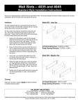
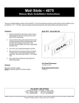
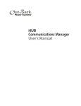
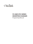
TM
User’s Guide
Includes Mounting, Installation, and
Product Registration
250
About OutBack Power Systems
OutBack Power Systems is a leader in advanced energy conversion technology. Our products
include true sine wave inverter/chargers, maximum power point charge controllers, system
communication components, as well as breaker panels, breakers, accessories, and assembled
systems.
Notice of Copyright
FLEXwareTM 250 User’s Guide© 2007 All rights reserved.
Disclaimer
UNLESS SPECIFICALLY AGREED TO IN WRITING, OUTBACK POWER SYSTEMS:
(a) MAKES NO WARRANTY AS TO THE ACCURACY, SUFFICIENCY OR SUITABILITY OF
ANY TECHNICAL OR OTHER INFORMATION PROVIDED IN ITS MANUALS OR OTHER
DOCUMENTATION.
(b) ASSUMES NO RESPONSIBILITY OR LIABILITY FOR LOSS OR DAMAGE, WHETHER DIRECT,
INDIRECT, CONSEQUENTIAL OR INCIDENTAL, WHICH MIGHT ARISE OUT OF THE USE OF SUCH
INFORMATION. THE USE OF ANY SUCH INFORMATION WILL BE ENTIRELY AT THE USER’S RISK.
Date and Revision
April, 2008 REV A
Contact Information
OutBack Power Systems
19009 62nd Ave. NE, Arlington, WA 98223
Phone (360)435-6030
Fax (360)435-6019
www.outbackpower.com
Warranty Introduction
Dear OutBack Customer,
Thank you for your purchase of OutBack products. We make every effort to assure our power
conversion products will give you long and reliable service for your renewable energy system.
As with any manufactured device, repairs might be needed due to damage, inappropriate use,
or unintentional defect. Please note the following guidelines regarding warranty service of
OutBack products:
• Any and all warranty repairs must conform to the terms of the warranty.
• All OutBack equipment must be installed according to their accompanying instructions and
manuals with specified over-current protection in order to maintain their warranties.
• The customer must return the component(s) to OutBack, securely packaged, properly
addressed, and shipping paid. We recommend insuring your package when shipping.
Packages that are not securely packaged can sustain additional damage not covered by the
warranty or can void warranty repairs.
• There is no allowance or reimbursement for an installer’s or user’s labor or travel time
required to disconnect, service, or reinstall the damaged component(s).
• OutBack will ship the repaired or replacement component(s) prepaid to addresses in the
continental United States, where applicable. Shipments outside the U.S. will be sent freight
collect.
• In the event of a product malfunction, OutBack cannot bear any responsibility for
consequential losses, expenses, or damage to other components.
Please read the full warranty at the end of this manual for more information.
IMPORTANT SAFETY INSTRUCTIONS
This manual contains important instructions for the FLEXware 250 that must be followed
during its installation and future maintenance for your safety and the integrity of the product.
SAVE THESE INSTRUCTIONS!
Requirements and Warnings
The OutBack Power Systems FLEXware 250 is listed by ETL as an accessory enclosure for
OutBack FX, GTFX, GVFX, and VFX Series Inverter/Chargers to UL standard UL 1741.
This enclosure is intended for battery circuits configured for 12 to 48 volts nominal.
Grounding Instructions – The frame of this enclosure should be connected to a grounded,
permanent wiring system. The AC and DC circuits are not bonded to the FLEXware 250
chassis. System grounding, when required by sections 690.41, 690.42, and 690.43 of the
National Electric Code, ANSI/NFPA 70, is the responsibility of the installer. For most installations,
the negative battery conductor should be bonded to the grounding system at one (and only
one) point in the DC system. All installations should comply with all national and local codes
and ordinances.
The equipment ground on FLEXware 250 is marked with this symbol:
FLEXware is designed for indoor mounting only with appropriate fasteners and a secure
mounting surface that can handle the full weight of an assembled system.
USE ONLY WITH COPPER
CONDUCTORS RATED
75° C MINIMUM
TORQUE DATA FOR SCREWDRIVER LUGS
WIRE SIZE
TORQUE
AWG
mm²
In Lbs
Nm
14 - 10
2.1 - 5.3
20
2.3
8
8.4
25
2.8
6-4
13.3 - 21.2
35
4.0
3
26.7
35
4.0
2
33.6
40
4.5
1
42.4
50
5.7
1/0
53.5
50
5.7
TORQUE DATA FOR BREAKER LUGS
BREAKER STUD
TORQUE
In Lbs
Nm
M8
20
2.3
1/4 - 20
35
4.0
5/16 - 18
50
5.7
3/8 - 16
225
25.5
DIN RAIL MOUNTED BREAKER TERMINALS - 22 In Lbs
www.outbackpower.com
375-0095-01-00 REV A
Welcome to OutBack Power Systems’ FLEXware 250
FLEXware is a convenient all-aluminum power system offering simple, code-compliant
installation of OutBack power electronics components. Three versions of FLEXware are
available:
• FLEXware 250 for single FX Series Inverter/Charger installations along with the desired AC
and DC disconnects
• FLEXware 500, which supports up to two FXs and two OutBack Series Charge Controllers,
accommodating both split-phase and/or higher power output as needed
• FLEXware 1000 accommodates up to four FXs and four OutBack Series Charge Controllers
Note: Both the FLEXware 500 and the FLEXware 1000 power systems provide locations for
FW-X240 Auto-Transformers, multiple DC shunts and other essential components required in
higher kW systems.
FLEXware 250 Parts List
The FLEXware 250 consists of an aluminum enclosure which can be used for either the AC or
DC side of an FX Series Inverter/Charger. Each FLEXware 250 includes:
• Installed ground bus bar
• Breaker Guard (for DC installations)
• Hardware Kits for mounting to an FX and for securing AC and DC breakers (refer to the
hardware bag label for a complete listing of parts)
• Cover Plate
• Breaker Label Kit
The chassis itself features conduit knockouts (see Figures 2-5) and knockouts for AC breakers
and DC breakers.
• DC installations include a slot for either a 175 or 250 amp OBDC breaker and slots for four
load breakers.
• AC installations allow for the optional 120/230 VAC Input/Output/Bypass Assembly
(IOB) kit.
Optional Parts:
• FW-IOB (Input/Output/Bypass Assembly) Kit for 120/230 VAC.
Getting to Know FLEXware 250
When mounting the FLEXware 250, the various breaker
slots must be in a vertical (forward facing) position
and cannot face downward or upward. Otherwise, the
breakers can malfunction.
FLEXware 250 mounted
as an AC enclosure
The FLEXware 250 also accommodates a shelf
or flat surface mounting as long as no breaker
slots are facing downward or upward.
DC Breaker Guard
FLEXware 250 mounted
as a DC enclosure (shown
with cover plate)
Figure 1: FLEXware 250
DC side
AC side
Figure 2: FW250 Enclosure
Unthreaded standoffs for attaching to FX
Unthreaded standoffs insert
into the AC or DC end of the FX
Inverter/Charger’s top casting
mounting holes.
Bottom 2” knockout
Ground Bus Bar
Figure 3: FLEXware 250 top view
DC input breaker slot
and Breaker Guard
mounting holes
DC breaker
slots
2” conduit
knockout
Unthreaded standoffs
½” conduit knockouts
Figure 4: FLEXware 250 DC side
AC breaker slots
Bypass Slide Plate
mounting holes
AC receptacle
knockoff
(off-grid
systems only)
Unthreaded
standoffs
2” conduit knockout
Figure 5: FLEXware 250
AC side
3/4” counduit
knockout
1” conduit
knockout
AC side
screw holes
DC side
screw holes
Remove these
screws to install
the FLEXware 250
on the AC side of
the FX (unthreaded
standoffs insert
into screw holes).
Remove these
screws to install
the FLEXware 250
on the DC side of
the FX (unthreaded
standoffs insert into
screw holes).
Figure 6: FLEXware 250 AC and DC chassis mounting locations
Unthreaded standoff
Screw hole
Figure 7: Side view of FLEXware 250 fitting onto AC side of an FX Series Inverter/Charger
Installing the FLEXware 250
With the FX secured to a surface (see FX Series Inverter/Charger Installation Manual for details),
the FLEXware 250 installs on either the DC or the AC side of the FX.
To install the FLEXware 250:
• Remove the cover plate screws and cover plate.
• Verify which knockouts will be removed for the installation and remove those knockouts.
• Remove only the two M5 X 12mm screws that secure the FX’s upper and lower casing
halves on whichever side (AC or DC) you first install the FLEXware 250.
• Insert the unthreaded standoffs into the holes on the FX and then insert two M5 X 25mm
screws, included with the FLEXware 250, into the standoffs and tighten.
• After all wiring has been completed, install the DCC and securing with four M5 X 12mm
screws (included with the DCC).
• Install each FLEXware 250 top cover plate and secure the #10 X 3/8” sheet metal screws.
For AC wiring instructions for the FLEXware 250, please see the schematics in the individual
AC Input/Output/Bypass Assembly (IOB) kits.
Figure 8: FLEXware 250 Dimensions
Figure 9: FLEXware 250-DC Wiring Diagram
10
The dashed lines represent the FLEXware 250 enclosure. This drawing
shows two units—one for an AC application and one for a DC application.
11
Product Registration
250
Please take a moment to register and provide
us with some important information in order to
improve our products.
Complete this form and return it to:
Outback Power Systems Inc.
19009 62nd Avenue NE
Arlington, WA 98223
Note: Complete one form for all installed FLEXware products.
FLEXware 250 Product Registration
System Owner
Name: ________________________________ Address: _ ______________________________
City, State, Zip Code: _____________________ Country: _ ______________________________
Telephone Number:______________________ E-mail:_ ________________________________
Installer
Company: _____________________________ Contractor Number:______________________
Installer Address:________________________ Installer City, State, Zip: ____________________ Installer E-mail:__________________________
System
System Install/Commission Date: ___________
Please circle type of application:
Off-Grid
Grid-Interactive
AC Coupled
Backup
Mobile
Enclosure Model Number(s):_______________ OB Kit Model Number:____________________
Sold by:_______________________________ Purchase Date: _ ________________________
The system is equipped with (circle one):
FW-X240
PSX-240
PSX-240-Relay
Please circle the three most important factors affecting your purchase decision:
Price
Product Reputation
Product Features
Reputation of OutBack Power Systems
Value
I am interested in receiving information concerning OutBack Power Systems products and events
(circle one):
Yes
No
Revision.2007-11-12
12
13
Corporate Office
19009 62nd Avenue NE
Arlington, WA 98223 USA
360-435-6030
European Sales Office
C/ Castelló, 17
08830 - Sant Boi de Llobregat
BARCELONA, España
+34.93.654.9568
www.outbackpower.com
900-0088-01-00 REV A