1
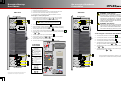
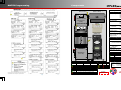
MATE3 Programming
Components
IMPORTANT:
Programming should be done by a qualified installer who is trained on programming inverter power systems. Failure to program accurate parameters for the
system could potentially cause equipment damage. Damage caused by inaccurate programming is not covered by the limited warranty for the system.
Major Components
HUB Communication Manager
(HUB4 or HUB10)
FLEXnet DC
Battery Monitor
FLEXpower System Products
FW250-AC-230V-EU
Surge Protector
(Inside)
Inverter/Charger
FX Series
VFX Series
GTFX Series
GVFX Series
GFX Series
AC Conduit Box
FW250-AC-230V-EU
DC Conduit Box
FW250-DC-125
FW250-DC-175
FW250-DC-250
System Display and
Controller
MATE2
MATE3
Charge Controller
FLEXmax 60
FLEXmax 80
Communications
Manager
HUB4
HUB10
System Display and Controller
(MATE3)
Battery Status LEDs
Inverter Status LEDs
AC
IN
MATE RTS
MAIN---------------3:02:14P
SUM STATUS
INV
SETUP ADV
MAT
RTS
E
Charge Controller
(FLEXmax 80)
Remote Temperature Sensor (RTS)
FLEXnet DC Monitor (FNDC)
Surge Protector
Inverter/
Charger
Customer-Supplied Components
AC Source
Utility Grid, or
AC Generator
Main Electrical Panel
(or overcurrent device for AC source)
Electrical Distribution Subpanel
(Load Panel)
In
Out
23.2 V
27.6 V
0.000 kW
AUX: OFF
0.0 A
0.0 A
0.0 kWH
Sleeping
Battery Bank
Photovoltaic (PV) Array
(with PV Combiner Box)
FNDC LED Indicators
FW250-DC-125
(175 or 250)
Color
> 90% (blinks if charge parameters are met)
Yellow
≥ 80%
Yellow
≥ 70%
Yellow
≥ 60%
Red
Color
Green
Battery Status LED Indicators
Surge Protector LEDs
12 V Inverter
24 V Inverter
48 V Inverter
Active
12.5 Vdc or higher
25.0 Vdc or higher
50.0 Vdc or higher
Yellow
Red
DC
Error
Phase
Yellow
11.5 to 12.4 Vdc
23.0 to 24.8 Vdc
46.0 to 49.6 Vdc
Yellow
Red
AC IN
Red
11.4 Vdc or lower
22.8 Vdc or lower
45.6 Vdc or lower
Yellow
Red
AC OUT
Inverter Status LED Indicators
900-0133-01-00 Rev A (FP1 QSG) EU EN.vsd\Page-1\2013-04-12
©2013 OutBack Power Technologies. All Rights Reserved.
Green
Inverter on (solid) or standing by (flash)
Yellow
AC source in use (solid) or standing by (flash)
Red
Inverter error or warning (see manual)
IMPORTANT:
Not intended for use with
life support equipment.
Battery State-of-Charge
Green
≥ 60% off, < 60% solid, < 50% blinks
Contact Technical Support:
Telephone: +1.360.618.4363
Email:
[email protected]
Web site:
www.outbackpower.com
Wire Sizes/Torque
Requirements
Mounting
1
WARNING: Fire/Explosion Hazard
Do not place combustible or flammable materials
within 3.7 m (12 feet) of the equipment. This unit
employs mechanical relays and is not ignitionprotected. Fumes or spills from flammable materials
could be ignited by sparks.
AC Wire Sizes and Torque Values
AC Conduit Box
Mounting the bracket to
the wall studs 14.6 cm
(16") apart.
Side View
Mechanical
Interlock
(Bypass)
WARNING: Personal Injury
AC Terminals
IMPORTANT:
Mounting the bracket
to plywood
#6 - 4
4.0
35
35
#3
4.0
35
35
#2
4.5
40
50
#1
5.6
50
70
1/0
5.6
50
Control Wiring Terminal Block:
The Inverter ON/OFF terminals are
used for connecting an external ON/
OFF switch. To use this feature, the
jumper must be removed. (See
installation manual for details.)
The AUX terminals provide a 12 Vdc
signal. The AUX terminals can be used
to start a generator or to control
external devices.
1.
1 Place the mounting bracket at the
desired height for the panel.
Torque requirements for
the conductor lugs
2.
2 Secure the mounting bracket to the
surface. Use all six mounting slots
provided on the bracket.
Wall Stud
Plywood
(if used)
Wall Board
FP1
Mounting
Panel
3
Mounting
Bracket
FP1
Mounting
Plate
Nm
In-lb
M8
2.3
20
¼ - 20
4.0
35
5/16 - 18
DC Circuit Breakers
Mounting
Bracket
3/8 - 16
5.6
25.4
Minimum DC Cable based on the
DC Circuit Breaker
DC
Torque
Circuit
Cable Size
Nm
In-lb
Breaker
125
70 mm2 (1/0)
2
5.6
50
50
175
70 mm (2/0)
25.4
225
225
250
120 mm2 (4/0)
25.4
225
Battery
Bank
CAUTION: Equipment Damage
Battery
Status
Monitor
DC Terminals
GFDI
Charge
Controller
6 Insert all three 1-inch nylon hole
6.
plugs into the rear slot access holes.
Torque
Circuit
Breaker Stud
4
5.
5 Secure the lower back flange of the
mounting plate to the wall (with
appropriate hardware).
When connecting cables from the inverter to the battery
terminals, ensure the proper polarity is observed.
Connecting the cables incorrectly can damage or destroy
the equipment and void the product warranty.
PV Array
Battery Cable Connections
without the FNDC
DC Conduit Box
Battery Cable Connections
with the FNDC
Flat Washer
6
5
Lock Washer
GFDI Cable Lug
Nut
Flat Washer
Bolt M8 x 1.25
Charge Controller
Battery (–) Lug
Lock Washer
Inverter
Battery (–) Lug
Lock Washer
Bolt M8 x 1.25
Charge Controller
Battery (–) Lug
Secure the mounting plate
to the wall at the three
locations. See 6 .
Nut
Surge Protector
Cable Lug
Mounting Surface
Inverter
Battery (–) Lug
900-0133-01-00 Rev A (FP1 QSG) EU EN.vsd\Page-2\2013-04-12
©2013 OutBack Power Technologies. All Rights Reserved.
25
16 – 25
2
To install the mounting bracket:
Slip the top of the mounting plate
over the angled lip of the wall
bracket.
20
2.8
Battery
Terminals
85 cm (33.5") tall X 50 cm (19.75") wide
4
4.
2.3
#8
Control
Wiring
Terminals
FP1 Dimensions:
3.
3 Lift the mounting plate above the wall
bracket.
#14 - 10
10
It is recommended that conductors be #6 AWG
THHN copper, or larger, rated to 75°C
(minimum) unless local code requires otherwise.
Mounting the bracket to
the wall studs 64 cm
(24") apart.
Clearance and access requirements may vary by
location. Maintaining a 91.4 cm (36 inches) clear
space in front of the system for access is
recommended. Consult local electric code to confirm
clearance and access requirements for the specific
location.
Torque
Nm
In-lb
2.5 – 6
GFCI Outlet
Use safe lifting techniques and standard safety
equipment when working with this equipment.
To mount the FP1 panel on the
bracket:
Wire Size
mm2
AWG
AC Circuit Breakers
Shunt
*must install upside-down on
units with both Shunt A and
Turbo Kit.
Isolator
Inverter Battery (–)
Terminal Post
Energize/Startup
Procedures
De-energize/Shutdown
Procedures
Pre-startup Procedures:
Side View
1.
Double-check all wiring connections.
2.
Inspect the enclosure to ensure no tools or debris has been left inside.
3.
Disconnect all AC loads at the backup (or critical) load panel.
4.
Disconnect the AC input feed to the FLEXpower ONE at the source.
To energize or start up the system:
AC Conduit Box
1.
AC Circuit Breakers
5
Mechanical
Interlock
(Bypass)
Side View
AC Conduit Box
Using a digital voltmeter (DVM), verify 12, 24, or 48 Vdc on the battery
terminals by placing the DVM leads on 1a and 1b . Confirm that the
voltage is correct for the inverter model. Confirm the polarity.
AC Circuit Breakers
3
Mechanical
Interlock
(Bypass)
CAUTION: Equipment Damage
Incorrect battery polarity will damage the inverter.
4
WARNING: Lethal Voltage
Review the system configuration to identify all possible
sources of energy. Ensure ALL sources of power are
disconnected before performing any installation or
maintenance on this equipment. Confirm that the
terminals are de-energized using a validated voltmeter
(rated for a minimum 1000 Vac and 1000 Vdc) to verify
the de-energized condition.
2.
Turn on (close) the GFDI circuit breaker. 1
3.
Verify the voltage on the PV terminal is in the correct range of open-circuit
voltage by placing the DVM leads on 2a and 2b . Confirm the polarity.
4.
Turn on (close) the PV input circuit breakers. 2
5.
Turn on (close) the DC circuit breaker from the battery bank to the inverter. 3
6.
Verify 230 Vac on the AC output circuit breakers by placing the DVM leads
on 3+ and 3– .
7.
Turn on (close) the AC output circuit breakers. 4
8.
Connect the AC source. Verify 230 Vac on the AC input circuit breakers
by placing the DVM leads on 4+ and 4– .
9.
Turn on (close) the AC input circuit breakers. 5
3
WARNING: Burn Hazard
Internal parts can become hot during operation. Do not
remove the cover during operation or touch any internal
parts. Be sure to allow them sufficient time to cool
down before attempting to perform any maintenance.
To de-energize or shut down the OutBack devices:
1. Turn off (open) the AC circuit breakers. 1
2. Turn off (open) the DC circuit breaker for the battery. 2
3. Turn off (open) the PV circuit breaker. 3
10. Turn on the AC disconnects at the load panel and test the loads.
4. Turn off (open) the GFDI circuit breaker. 4
3– 4–
Functional
Test Points
5. *Verify 0 Vdc on the DC input terminals of the inverter by
placing the voltmeter leads on 1a and 1c .
4+
6. *Verify 0 Vdc on the PV terminal by placing the voltmeter leads
on 2a and 2c .
3+
Battery Voltage
Test Points
3
DC Circuit Breakers
PV Array
1b
Circuit Breaker Terminal
connected to the Battery
Positive (+) Cable
1c
Circuit Breaker Terminal
connected to the Inverter
DC Positive (+) Cable
7. *Verify 0 Vac on the AC output circuit breakers by placing the
voltmeter leads on 3+ and 3– .
1
2
2a
PV Negative (–) Terminal
on the Charge Controller
2b
Circuit Breaker terminal
for the PV
2c
PV Positive (+) Terminal
on the Charge Controller
1a
Battery
Bank
GFDI
2
PV Array
1
AC OUT Voltage
Test Points
DC Conduit Box
3+
3–
900-0133-01-00 Rev A (FP1 QSG) EU EN.vsd\Page-3\2013-04-12
©2013 OutBack Power Technologies. All Rights Reserved.
4–
DC Conduit Box
1b
AC IN Voltage
Test Points
4+
4
DC Circuit Breakers
PV Voltage Test Points
Battery
Bank
GFDI
1a
Battery Negative (–)
Terminal on the Inverter
1c
2b
2c
2a
*See the illustration that identifies the locations of the functional
test points that is included with the Startup Procedures.
General Wiring
AC Source
(single)
AC Distribution
Panel
IMPORTANT: Example only. Actual wiring may vary.
Factory wiring not shown. All configurations must
comply with local and national electric codes. Consult your
local electric authority to ensure compliance.
N
L1
(or disconnect device)
Input
IMPORTANT:
N
Neutral
Photovoltaic Array (PV)
Indoor installation only.
AC IN
Output
Bypass
L1
Outlet
AC LEGEND
Neutral
HOT L1
N
30 A Circuit
Breaker
(Maximum)
L1
FLEXware PV8
Ground
MAIN---------------3:02:14P
Ground
INV
AC IN
SUM STATUS
MATE
SETUP ADV
If the FLEXnet DC battery monitor
is not installed, the DC shunt will
not be installed.
RTS
If the DC shunt is not installed,
connect the DC negative (–) cable
directly to the DC negative (–)
terminal on the inverter.
Ground
Electrode
Conductor
I
I
I
I
I
I
I
I
O
O
O
O
O
O
O
O
DC Negative (—)
Terminal on the
Inverter
2
DC Negative (—) Cable
2
DC LEGEND
AC Subpanel
L1
HOT
Negative
NEUTRAL
In
Out
23.2 V
27.6 V
0.000 kW
AUX: OFF
Positive
0.0 A
0.0 A
0.0 kWH
Sleeping
N
Loads
(230 Vac)
Ground
1
N
Battery Bank
Battery Status
30 A Circuit Breaker
(Maximum)
GFDI
L1
GROUND
Charge Controller
(RTS)
PV Circuit Breaker
900-0133-01-00 Rev A (FP1 QSG) EU EN.vsd\Page-4\2013-04-12
©2013 OutBack Power Technologies. All Rights Reserved.
1
Connects to the terminal on the circuit breaker
that is opposite the inverter DC cable.
Vented Battery Enclosure