1
Microcontroller Technical Information
SM78K0
78K0 System Simulator
Document No.
ZBG-CD-08-0009
Date issued
March 12, 2008
Issued by
Development Tool Solution Group
Multipurpose Microcomputer Systems Division
Microcomputer Operations Unit
NEC Electronics Corporation
Usage Restrictions
Related
documents
SM78K Series Ver. 2.52 Operation:
U16768EJ1V0 (1st edition)
Notification
classification
√
SM78K Series Ver. 2.30 or later
External Part User Open Interface
Specifications:
1/2
Usage restriction
Upgrade
Document modification
Other notification
U15802EJ1V0 (1st edition)
1. Affected product
SM78K0 Ver. 2.70
2. New restrictions
The following restrictions on debug functions (No. 13 to No. 16) and restrictions on simulation functions
(No. 18 to No. 25) for the SM78K0 have been added.
[Restrictions on debug functions]
y No. 13
Restriction on installation of multiple simulators
y No. 14
Restriction on Help display
y No. 15
Restriction on timer event/break events
y No. 16
Restriction on port register display in SFR window
[Restrictions on simulation functions]
y No. 18
Restriction on menu displayed in Parts window
y No. 19
Restriction on display of waveforms output from 8-bit timers A0 and B0
y No. 20
Restriction on Parts window operation after CPU reset
y No. 21
Restriction on 7-/14-seg LED in Parts window
y No. 22
Restriction on SFR Event & Action window
y No. 23
Restriction on timer 01 when using μPD780078
y No. 24
Restriction on serial interface when using μPD780058
y No. 25
Restriction on LCD panel window
3. Workarounds
The following workarounds are available for these restrictions. See the attachment for details.
[Restrictions on debug functions]
y No. 13
Uninstall SM78K0 V2.70 and then install it again.
y No. 14
Open the help from the Start menu.
y No. 15
There is no workaround.
y No. 16
There is no workaround.
ZBG-CD-08-0009
2/2
[Restrictions on simulation functions]
y No. 18
There is no workaround.
y No. 19
There is no workaround.
y No. 20
There is no workaround.
y No. 21
There is no workaround.
y No. 22
There is no workaround.
y No. 23
There is no workaround.
y No. 24
There is no workaround.
y No. 25
There is no workaround.
4. Modifications
Modifications for these restrictions are as follows. See the attachment for details.
[Restrictions on debug functions]
y No. 13
This issue will be corrected in the next version (planned to be released at the end of
March 2008).
y No. 14
This issue has been corrected in the SM78K0 Ver. 2.70.
y No. 15
This issue has been corrected in the SM78K0 Ver. 2.70.
y No. 16
This issue has been corrected in the SM78K0 Ver. 2.70.
[Restrictions on simulation functions]
y No. 18
This issue has been corrected in the SM78K0 Ver. 2.70.
y No. 19
This issue has been corrected in the SM78K0 Ver. 2.70.
y No. 20
This issue has been corrected in the SM78K0 Ver. 2.70.
y No. 21
This issue has been corrected in the SM78K0 Ver. 2.70.
y No. 22
This issue has been corrected in the SM78K0 Ver. 2.70.
y No. 23
This issue has been corrected in the SM78K0 Ver. 2.70.
y No. 24
This issue has been corrected in the SM78K0 Ver. 2.70.
y No. 25
This issue will be corrected in the next version (planned to be released at the end of
March 2008).
5. List of restrictions
See the attachment for a product history and a list of restrictions.
6. Document revision history
Document Number
Issued on
Description
SBG-TT-0139
June 17, 2002
Newly created.
SBG-DT-03-0158
May 23, 2003
Addition of new restrictions (simulation functions No. 36 to No. 44)
ZBG-CD-08-0009
March 12, 2008
Deletion of restrictions which have been corrected in Ver. 2.52
Modification of restriction numbers
Addition of restrictions (debug functions No. 13 to No. 16, simulation
functions No. 18 to No. 25)
ZBG-CD-08-0009 Attachment - 1/24
List of Restrictions on SM78K0
1. PRODUCT HISTORY
This section explains the restrictions on the SM78K0. The restrictions are classified into the following
two types.
• Restrictions on debug functions
• Restrictions on simulation functions
Among the restrictions reported in the previous edition (SBG-DT-03-0158), restrictions that have been
corrected in SM78K0 V2.52 are deleted in this edition. In conjunction with this deletion, restrictions are
renumbered in this document.
Among the restrictions listed in the previous edition (SBG-DT-03-0158), the following items that depend
on the SM78K0 specifications have been revised as follows.
• Items related to the contents in the user’s manual: Moved to 4. CHANGES IN USER’S MANUAL.
• Items other than above: Moved to 3. CAUTIONS.
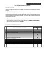
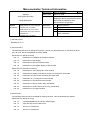
1.1 Restrictions on Debug Functions (List)
No.
Bugs and Changes/Additions to Specifications
Version
V2.52
V2.70
×
×
1
Restriction on source file name
2
Restriction on Coverage-Efficiency View dialog box
Described in Chapter 4.
3
Restriction that symbols with the func#var format cannot be converted into addresses
Described in Chapter 4.
4
Restriction on executing slow-motion
Described in Chapter 3.
5
Restriction on Watch window
6
Restriction on saving a project file
Described in Chapter 3.
7
Restriction on Help display
Described in Chapter 4.
8
Restriction on switching active project in PM+
9
Restriction on changing file type
Described in Chapter 3.
10
Restriction on source path addition
Described in Chapter 4.
11
Restriction on redrawing the window
Described in Chapter 3.
12
Restriction on event setting
Described in Chapter 3.
13
Restriction on installation of multiple simulators
−
×
14
Restriction on Help display
×
{
15
Restriction on timer event/break events
×
{
16
Restriction on port register display in SFR window
×
{
×
−
×
×
×: Applicable, {: Not applicable, −: Not relevant
ZBG-CD-08-0009 Attachment - 2/24
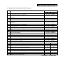
1.2 Restrictions on Simulation Functions (List)
No.
Bugs and Changes/Additions to Specifications
Version
V2.52
V2.70
1
IIC arbitration function not supported
Described in Chapter 3.
2
Bit shift detection function of SIO1 (3-wire, with automatic transfer function) not
Described in Chapter 3.
supported
3
1-bit shift output function of meter controller not supported
Described in Chapter 3.
4
IEBus function not supported
Described in Chapter 3.
Oscillation clock selection function by SFR not supported (μPD780973
Described in Chapter 3.
5
Subseries)
6
ROM correction function not supported
Described in Chapter 3.
7
Bug in interrupt
Described in Chapter 4.
8
Bug in ADCR0 snd ADCR1 registers
Described in Chapter 3.
9
Bug in time of the timer operating with the subclock
Described in Chapter 4.
10
Bug in setting watch timer (μPD780344, 780354 Subseries)
Described in Chapter 3.
11
Bug in scroll bar display
Described in Chapter 4.
12
Restriction on minimizing I/O Panel window
Described in Chapter 4.
13
LIN function of UART6 not supported
Described in Chapter 3.
14
Internal oscillator not supported
Described in Chapter 3.
15
Clock monitor not supported
Described in Chapter 3.
16
Power-on clear not supported
Described in Chapter 3.
17
Low-voltage detection circuit (LVI) not supported
Described in Chapter 3.
18
Restriction on menu displayed in Parts window
×
{
19
Restriction on display of waveforms output from 8-bit timers A0 and B0
×
{
20
Restriction on Parts window operation after CPU reset
×
{
21
Restriction on 7-/14-seg LED in Parts window
×
{
22
Restriction on SFR Event & Action window
×
{
23
Restriction on timer 01 when using μPD780078
×
{
24
Restriction on serial interface when using μPD780058
×
{
25
Restriction on LCD panel window
×
×
×: Applicable, {: Not applicable
ZBG-CD-08-0009 Attachment - 3/24
2. DETAILS OF RESTRICTIONS
2.1 Details of Restrictions on Debug Functions
No. 1 Restriction on source file name
[Description]
If a file name that includes a minus (−) or plus (+) sign exists in a source file, a break point cannot be set
in the debugger.
[Workaround]
Change the file name so that it does not include a minus (−) or plus (+) sign.
[Correction]
This issue will be corrected in the next version.
No. 5 Restriction on Watch window
[Description]
If a bit variable or bit field is displayed in the Watch window, the digit is not displayed as 1 digit, but as
16 digits (in binary, not 0b1 but 0b0000000000000001). The contents of data are correct.
[Workaround]
There is no workaround.
[Correction]
This issue will be corrected in the next version. After correction, the bit variables and bit fields are
displayed as 1 digit (0b1 or 0b0).
No. 8 Restriction on switching active project in PM+
[Description]
When both PM+ and the SM78K0 are running and the active project is switched by PM+, if the
activated project does not include the project file (.pri) of the debugger, the load module loaded by the
previous active project is not reset and remains as is.
[Workaround]
Before creating a project, select “Debugger settings…” on the [Tool] menu of PM+ to open the
Debugger Settings dialog box, and then select “Execute symbol reset after download” in the dialog box.
[Correction]
This issue will be corrected in the next version.
No. 13 Restriction on installation of multiple simulators
[Description]
If a simulator (SM850, SM78K4 or SM78K0S) of V2.52 or earlier is installed in a computer where
SM78K0 V2.70 is installed and then the simulator other than the SM78K0 is uninstalled, some files
required by SM78K0 V2.70 are deleted. As a result, some bitmaps can no longer be displayed in the
Parts window.
[Workaround]
Uninstall SM78K0 V2.70 and then install it again.
ZBG-CD-08-0009 Attachment - 4/24
[Correction]
This issue will be corrected in the next version.
No. 14 Restriction on Help display
[Description]
If an attempt is made to open the help from the simulator in the Windows XP SP2 environment, it is not
displayed correctly. In addition, if an attempt is made to open the help by selecting the [Help] menu on
the menu bar or by pressing the F1 key, the help is displayed erroneously or diagrams in the help are
not displayed.
[Workaround]
Open the help from the Start menu.
[Correction]
This issue has been corrected in Ver. 2.70.
No. 15 Restriction on timer event/break events
[Description]
If the same event is set as a timer event condition and a break event condition, the measured execution
time is erroneously displayed as follows.
y Nothing is displayed.
y The time of execution of only one instruction is displayed.
[Workaround]
There is no workaround.
[Correction]
This issue has been corrected in Ver. 2.70.
No. 16 Restriction on port register display in SFR window
[Description]
When ports are used in input mode, the level of the signals input to the port registers displayed in the
SFR window cannot be confirmed. (Incorrect values may be read out.)
*
Values read in the SFR window are incorrect but the values read by executing a microcontroller
instruction are correct.
[Workaround]
There is no workaround.
[Correction]
This issue has been corrected in Ver. 2.70.
ZBG-CD-08-0009 Attachment - 5/24
2.2 Details of Restrictions on Simulation Functions
No. 18 Restriction on menu displayed in Parts window
[Description]
Even if [Show Menu] is clicked in the Parts window system menu (which is displayed by clicking the
program icon on the title bar), hiding and showing of the menu display cannot be switched.
[Workaround]
There is no workaround.
[Correction]
This issue has been corrected in Ver. 2.70.
No. 19 Restriction on display of waveforms output from 8-bit timers A0 and B0
[Description]
When 8-bit timer A0 or B0 of the μPD780344, μPD780354, μPD780344Y and μPD700354Y
microcontrollers is used as a carrier generator, the output waveforms cannot be monitored in the
Output Timing Chart window.
Even if the timer output is disabled when the timer is used for purposes other than the carrier generator,
the waveform may continue to be displayed in the Output Timing Chart window.
[Workaround]
There is no workaround.
[Correction]
This issue has been corrected in Ver. 2.70.
No. 20 Restriction on Parts window operation after CPU reset
[Description]
When a CPU reset occurs, the buttons shown in the Parts window are reset to the initial state but the
level of the signals connected to the buttons are not.
[Workaround]
There is no workaround.
[Correction]
This issue has been corrected in Ver. 2.70.
No. 21 Restriction on 7-/14-seg LED in Parts window
[Description]
Displays of 7-/14-seg LEDs in the Parts window are switched only at the valid edge of the digit signals.
[Workaround]
There is no workaround.
[Correction]
This issue has been corrected in Ver. 2.70.
ZBG-CD-08-0009 Attachment - 6/24
No. 22 Restriction on SFR Event & Action window
[Description]
The action set in the SFR Event & Action window does not occur during stepwise execution.
If FETCH is specified as an action in the SFR Event & Action window, the action does not occur.
[Workaround]
There is no workaround.
[Correction]
This issue has been corrected in Ver. 2.70.
No. 23 Restriction on timer 01 when using μPD780078
[Description]
When a μPD780078 microcontroller (μPD780076, μPD780078, μPD78F0078, μPD780076Y,
μPD780078Y or μPD78F0078Y) is used, no interrupt is output from 16-bit timer/event counter 01.
[Workaround]
There is no workaround.
[Correction]
This issue has been corrected in Ver. 2.70.
No. 24 Restriction on serial interface when using μPD780058
[Description]
When
a
μPD780058 microcontroller (μPD780053, μPD780054, μPD780055, μPD780056,
μPD780053Y, μPD780054Y, μPD780055Y, μPD780056Y, μPD780058, μPD78F0058, μPD780058Y, or
μPD78F0058Y) is used, UART communication that uses RXD1/TXD1 in serial interface channel 2
does not operate.
[Workaround]
There is no workaround.
[Correction]
This issue has been corrected in Ver. 2.70.
No. 25 Restriction on LCD panel window
[Description]
When using the LCD Panel window, if the segment which is displayed first is not the first segment (top
of a segment), the segment may not be displayed as is set.
[Workaround]
There is no workaround.
[Correction]
This issue will be corrected in the next version.
ZBG-CD-08-0009 Attachment - 7/24
3. CAUTIONS
3.1 Differences Between Simulator and Target Device
No. 1
Unsupported peripheral functions
The following peripheral functions are not supported.
• IIC arbitration function
• LIN function of serial interface UART6
• Function to detect bit shift due to busy signal of serial interface SIO1
• 1-bit shift output function of meter controller
• IEBUS controller function
• Oscillation clock switch function via SFRs of μPD780973 and μPD7809734
• ROM correction function
• Clock monitor function
• Power-on-clear circuit
• Low-voltage detector
• Operation of CPU and peripheral functions according to internal low-speed oscillator
No. 2
A/D converter
If a value is read from a conversion result register during A/D conversion, the value upon completion of
the A/D conversion is read out in the simulator. In some target devices, the value before conversion is
read out.
If A/D conversion ends at the same time as conversion is stopped (by writing to the relevant control
register via an instruction), the A/D converter stops after completion of conversion in the simulator. In
some target devices, the A/D converter stops before completion of conversion.
3.2 Cautions on Debug Functions
No. 1
IAR compiler
The IAR compiler V3.30A or above is supported.
No. 2
Switching application while icon is being dragged
If an application is switched for any reason while an event icon is being dragged, the icon cannot be
dropped. In such a case, release the drag status using the ESC key.
No. 3
Read-only project file can be overwritten
Even if the file attribute is set to read-only in the Windows 2000 environment, project files can be
overwritten if the project files are overwrite-saved via the simulator.
ZBG-CD-08-0009 Attachment - 8/24
No. 4
Redrawing window
If the caret is moved when a window such as the Memory window or Coverage window becomes active,
the line where the caret was placed may appear blank.
Click the [Refresh] button or click on the blanked line to restore the original display.
No. 5
Breakpoint setting during program execution
Setting and clearing of breakpoints are not possible during program execution, while the tracer function
is on. To enable these operations, click [Tracer On] in the [Option] menu to disable the trace function.
No. 6
Execution of slow-motion during program execution
If [Slowmotion] is selected from the [Run] menu in the simulator during program execution, a forced
break can no longer be executed. In such a case, forcibly terminate the simulator. (The [Slowmotion]
menu is not usually available during program execution, but it is available under some conditions.)
No. 7
Changing file type by inputting a character string such as "*.hex"
Even if the display of the extension select area is changed by specifying the file type as "*.hex" in the
file selection area in a file selection dialog box such as the Download dialog box or Browse dialog box,
the change may not be reflected internally.
Specify the file type in the Files of Type list.
No. 8
Event setting
If the address at which a label or variable is allocated in the program is changed due to modification or
rebuilding of the program after an event such as a breakpoint or a snap event is set, the address at
which the event is set is not reflected. Therefore, set the event again, as necessary.
3.3 Cautions on Simulating Functions
No. 1
Input Timing Chart Editor window, Output Timing Chart Editor window and Input 0/1 Editor
window
Do not use the data search function of the Input Timing Chart Editor window, Output Timing Chart
Editor window, and Input 0/1 editor window because its search performance is poor.
No. 2
Buttons of external parts
The default value of a pin when a button is connected is 0 for both the active-high and active-low
models. As a workaround, set Hi → 0 and Lo → 1 using the pull-up/pull-down function of an external
part.
ZBG-CD-08-0009 Attachment - 9/24
4. CHANGES IN USER’S MANUAL
This section describes changes in the SM78K Series System Simulator Operation User’s Manual
(U16768EJ1) and SM78K Series System Simulator External Part User Open Interface Specifications
(U15802EJ1).
4.1 Changes in Operation
This section describes changes in the SM78K Series System Simulator Operation User’s Manual
(U16768EJ1). Some parts are underlined to clarify the changed points.
No. 1
Change in Operating Environment
¾ Location
1.4.2 Software environment on page 16
¾ Before change
(1)
Operating system (any of the following)
TM
Windows98, Windows2000, Windows NT 4.0, Windows Me, Windows XP Home Edition,
Windows XP Professional
¾ After change
(1)
Operating system (any of the following)
Windows2000, Windows XP Home Edition, Windows XP Professional
No. 2
Addition to Debugger Option dialog box
¾ Location
Under Reference on page 87
¾ Added description
Caution:
When a project is saved in the simulator and then a new source path is added in
PM+, the new source path is not added to the simulator. In this case, add the
source path manually.
ZBG-CD-08-0009 Attachment - 10/24
No. 3
Change in Source window
¾ Location
Above Figure 6-24 on page 132
¾ Before change
Caution:
If program codes is described in an include file and these codes are included in
multiple files, the line numbers and addresses do not correspond on a
one-to-one bases. In such an include file, function that indicates the
correspondence relationship between line numbers and addresses dose not
correctly operate.
¾ After change
Caution 1: If program codes is described in an include file and these codes are included in
multiple files, the line numbers and addresses do not correspond on a
one-to-one bases. In such an include file, function that indicates the
correspondence relationship between line numbers and addresses dose not
correctly operate.
Caution 2: Up to 65,535 lines of a C source file can be displayed. If the number of lines
exceeds 65,535, divide the source file.
No. 4
Change in Watch window
¾ Location
Above Figure 6-36 on page 176
¾ Before change
Caution:
If a local variable and a global variable exist with the same name, the local
variable takes priority.
¾ After change
Caution 1: If a local variable and a global variable exist with the same name, the local
variable takes priority.
Caution 2: Multiple lines cannot be selected in the Watch window.
Caution 3: Up to 10,000 lines can be displayed in the Watch window.
ZBG-CD-08-0009 Attachment - 11/24
No. 5
Addition to Add Watch dialog box
¾ Location
Under the index table for scope specification on page 189
¾ Added description
If an in-function static variable or an auto variable is specified in the format of func#var, the value is
displayed as a question mark. In such a case, specify the variable in the format of file#func#var or
prog$file#func#var.
No. 6
Change in SFR dialog box
¾ Location
Last line in description of (1) Display, Pick Up, No Display (display SFR selection area) on page
214
¾ Before change
When selecting a SFR from the list, two or more registers can be selected by clicking any of the
above buttons with the Ctrl or Shift key held down.
¾ After change
When selecting a SFR from the list, two or more registers can be selected by clicking any of the
above buttons with the Ctrl or Shift key held down. The display order cannot be changed while
multiple lines are selected. (The Arrange area appears dimmed.)
No. 7
Addition to Trace window
¾ Location
Above Figure 6-46 on page 219
¾ Added description
Caution:
When no trace result is displayed due to any reason such as immediately after
the computer has booted, the Help is not displayed even if the F1 key is pressed.
In such a case, select the [Help] menu → [Current Window] to open the Help.
ZBG-CD-08-0009 Attachment - 12/24
No. 8
Addition to Coverage-Efficiency View dialog box
¾ Location
Above Figure 6-53 on page 252
¾ Added description
Caution:
In the English version windows, when an item consisting of 21 characters or
more is included and the total number of items exceeds 12 in the survey list, the
last line is hidden behind the horizontal scroll bar. In this case, add one or more
dummy items at the end of the list.
No. 9
Change in Timer dialog box
¾ Location
Description in (4) Execution time display area on page 304
¾ Before change
This area displays the result of measuring the execution time of the program.
¾ After change
This area displays the result of measuring the execution time of the program.
Caution:
When the CPU is operating on the subclock, a slight error occurs in the
measured time (see examples below.)
Expected value of measurement time
500 ms
15.6 ms
Measured time displayed
498.0736 ms
15.5652 ms
ZBG-CD-08-0009 Attachment - 13/24
No. 10 Change in SFR Event & Action window
¾ Location
Description in the table in (4) Action Set (action setting area) on page 325
¾ Before change
Interrupt
If this check box is checked, an interrupt signal is generated as an action.
Select an interrupt name from the drop-down list, or input from the keyboard.
For the specifiable interrupt names, refer to the user's manual of the device
used.
¾ After change
Interrupt
If this check box is checked, an interrupt signal is generated as an action.
Select an interrupt name from the drop-down list, or input from the keyboard.
For the specifiable interrupt names, refer to the user's manual of the device
used.
If one or more interrupts have the same interrupt address, only the
representative one is displayed.
No. 11 Addition to Input 0/1 Editor window
¾ Location
Above Figure 6-70 on page 326
¾ Added description
Caution:
This window cannot be maximized even if attempted.
No. 12 Addition to Input timing Chart Editor window
¾ Location
Above Figure 6-71 on page 332
¾ Added description
Caution:
This window cannot be maximized even if attempted.
ZBG-CD-08-0009 Attachment - 14/24
No. 13 Addition to Output Timing Chart window
¾ Location
<1> Above Figure 6-75 on page 345
<2> Under Reference in (3) Timing chart display area on page 347
¾ Added description
<1> Caution:
This window cannot be maximized even if attempted.
<2> Caution:
When “INT: interrupt flag” is selected in the Pin Setting dialog box, the
name of an interrupt source that has occurred may not be displayed. (If
one or more interrupts occur at the same time, for example, only one
interrupt is displayed.)
If one or more interrupts have the same interrupt address, only the
representative one is displayed.
No. 14 Change in Parts window
¾ Location
In Caution on page 352
¾ Before change
Caution:
For the operation of the I/O panel when the CPU is reset, refer to "4. 1. 3
Operation of external parts at CPU reset".
¾ After change
Caution 1: For the operation of the I/O panel when the CPU is reset, refer to "4. 1. 3
Operation of external parts at CPU reset".
Caution 2: The scroll bar is not displayed, even if a component is moved at an end of the
Parts window or a component which is too large to be displayed in the window
is loaded. In such a case, the scroll bar can be displayed by resizing the Parts
window.
Caution 3: If the Parts window is minimized while it is in the placement mode, the window
size cannot be restored even if the Parts window button, which is displayed on
the task bar, is clicked. In such a case, right-click the Parts window button on
the task bar and click “Restore”.
Caution 4: When a customized component is moved in the Parts window and then the
components are reloaded into a project file or reloaded by using the Customize
menu in the Parts window, the component is displayed at the position before it
was moved.
ZBG-CD-08-0009 Attachment - 15/24
No. 15 Change in Level Gauges window
¾ Location
<1> Description of SB/D in the table in (2) Connection information setting area on page 415
<2> In <Inputting via scroll bar> in Setting on page 416
¾ Before change
<1>
SB/D
This check box specifies the type of the level gauge to be displayed.
If this box is checked, the level gauge is displayed as a dial; if it is not checked,
the level gauge is displayed as a scroll bar.
<2>
By moving the scroll thumb, the analog value, which is displayed in black, can be changed.
When the analog value has reached the value to be input, click the right button of the mouse on the
scroll bar. In this way, the displayed analog value can be input. At this time, the value is displayed in
red.
¾ After change
<1>
SB/D
This check box specifies the type of the level gauge to be displayed.
If this box is checked, the level gauge is displayed as a dial; if it is not checked,
the level gauge is displayed as a scroll bar.
Caution: If a scroll-bar-type level gauge is connected to each of multiple analog
input pins, and they are reconnected to a dial-type level gauge, or vice versa, the
position at which each level gauge is displayed may overlap.
<2>
By moving the scroll thumb, the analog value, which is displayed in black, can be changed.
When the analog value has reached the value to be input, click the right button of the mouse on the
scroll bar. In this way, the displayed analog value can be input. At this time, the value is displayed in
red.
Caution:
When the right mouse button is clicked to input a value, the context menu is
displayed, but the input was performed correctly.
ZBG-CD-08-0009 Attachment - 16/24
No. 16 Change in Internal Interrupt Button window
¾ Location
Caution in (2) Interrupt (internal interrupt name setting area) on page 424
¾ Before change
Caution:
For the specifiable interrupt names, refer to the user's manual of the device
used.
¾ After change
Caution 1: For the specifiable interrupt names, refer to the user's manual of the device
used.
Caution 2: If one or more interrupts have the same interrupt address, only the
representative one is displayed.
No. 17 Change in Expansion window
¾ Location
Reference in B. 2 Activation on page 489
¾ Before change
Reference: Each .tcl file is installed in NECTools32\BIN\idtcl\tools.
¾ After change
Reference: Each .tcl file is installed in the following folder.
NEC Electronics Tools\product name\version\bin\idtcl\tools
(The product name will be either of SM78K4, SM78K0, or SM78K0S.)
ZBG-CD-08-0009 Attachment - 17/24
4.2 Changes in External Part User Open Interface Specifications
This section describes changes in the SM78K Series System Simulator External Part User Open Interface
Specifications (U15802EJ1). Some parts are underlined to clarify the changed points.
No. 1
Change in operating environment
¾ Location
1.3.1 Development environment on page 15
¾ Before change
(1)
Software environment: Windows98, Windows2000, Windows NTTM4.0
Microsoft Visual C++ V5.00 or later
¾ After change
(1)
Software environment: Windows2000, WindowsXP
Microsoft Visual C++ V6.00 or later
No. 2
Change in 1.4 Cautions When Transferring External Parts...
¾ Location
1.4.2 Change of make environment on page 15
¾ Before change
(1)
Add the uparts32.cpp file to the project.
uparts32.cpp is in .\smp78kx\sm78kx under the SM78K installation directory (e.g.
c:\nectools32).
¾ After change
(1)
Add the uparts32.cpp file to the project.
uparts32.cpp is in the following folder.
NEC Electronics Tools\product name1\version\smp product name2\product name1\
* Product name1: Either SM78K4, SM78K0, or SM78K0S
Product name2: Either 78K4, 78K0, or 78K0S
ZBG-CD-08-0009 Attachment - 18/24
No. 3
Change in Example of Parts Customized via Parts Window
¾ Location
Change of entire contents of <3> Definition file UPsw00.def on page 87
Deletion of <4> Make file UPsw00.mak on pages 88 to 91
Addition of <4> Project file UPsw00.dsp on pages 88 to 91
Addition of <5> Workspace file UPsw00.dsw on pages 88 to 91
¾ Before change
See the relevant pages shown in Location above.
¾ After change
<3> Definition file UPsw00.def
(1/1) UPsw00.def
LIBRARY UPSW00
DESCRIPTION
'User Open I/F Panel sw00'
EXPORTS
UParts_sw00
ZBG-CD-08-0009 Attachment - 19/24
<4> Project file UPsw00.dsp
(1/4) UPsw00.dsp
# Microsoft Developer Studio Project File - Name="UPsw00" - Package Owner=<4>
# Microsoft Developer Studio Generated Build File, Format Version 6.00
# ** DO NOT EDIT **
# TARGTYPE "Win32 (x86) Dynamic-Link Library" 0x0102
CFG=UPsw00 - Win32 Debug
!MESSAGE This is not a valid makefile. To build this project using NMAKE,
!MESSAGE use the Export Makefile command and run
!MESSAGE
!MESSAGE NMAKE /f "UPsw00.mak".
!MESSAGE
!MESSAGE You can specify a configuration when running NMAKE
!MESSAGE by defining the macro CFG on the command line. For example:
!MESSAGE
!MESSAGE NMAKE /f "UPsw00.mak" CFG="UPsw00 - Win32 Debug"
!MESSAGE
!MESSAGE Possible choices for configuration are:
!MESSAGE
!MESSAGE "UPsw00 - Win32 Release" (based on "Win32 (x86) Dynamic-Link Library")
!MESSAGE "UPsw00 - Win32 Debug" (based on "Win32 (x86) Dynamic-Link Library")
!MESSAGE
# Begin Project
# PROP AllowPerConfigDependencies 0
# PROP Scc_ProjName ""
# PROP Scc_LocalPath ""
CPP=cl.exe
MTL=midl.exe
RSC=rc.exe
ZBG-CD-08-0009 Attachment - 20/24
(2/4) UPsw00.dsp
!IF "$(CFG)" == "UPsw00 - Win32 Release"
# PROP BASE Use_MFC 0
# PROP BASE Use_Debug_Libraries 0
# PROP BASE Output_Dir "Release"
# PROP BASE Intermediate_Dir "Release"
# PROP BASE Target_Dir ""
# PROP Use_MFC 0
# PROP Use_Debug_Libraries 0
# PROP Output_Dir "Release"
# PROP Intermediate_Dir "Release"
# PROP Target_Dir ""
# ADD BASE CPP /nologo /MT /W3 /GX /O2 /D "WIN32" /D "NDEBUG" /D "_WINDOWS" /D "_MBCS" /D
"_USRDLL" /D "UPSW00_EXPORTS" /YX /FD /c
# ADD CPP /nologo /MT /W3 /GX /O2 /D "WIN32" /D "NDEBUG" /D "_WINDOWS" /D "_MBCS" /D
"_USRDLL" /D "UPSW00_EXPORTS" /YX /FD /c
# ADD BASE MTL /nologo /D "NDEBUG" /mktyplib203 /win32
# ADD MTL /nologo /D "NDEBUG" /mktyplib203 /win32
# ADD BASE RSC /l 0x411 /d "NDEBUG"
# ADD RSC /l 0x411 /d "NDEBUG"
BSC32=bscmake.exe
# ADD BASE BSC32 /nologo
# ADD BSC32 /nologo
LINK32=link.exe
# ADD BASE LINK32 kernel32.lib user32.lib gdi32.lib winspool.lib comdlg32.lib advapi32.lib shell32.lib
ole32.lib oleaut32.lib uuid.lib odbc32.lib odbccp32.lib /nologo /dll /machine:I386
# ADD LINK32 kernel32.lib user32.lib gdi32.lib winspool.lib comdlg32.lib advapi32.lib shell32.lib ole32.lib
oleaut32.lib uuid.lib odbc32.lib odbccp32.lib /nologo /dll /machine:I386
ZBG-CD-08-0009 Attachment - 21/24
(3/4) UPsw00.dsp
!ELSEIF "$(CFG)" == "UPsw00 - Win32 Debug"
# PROP BASE Use_MFC 0
# PROP BASE Use_Debug_Libraries 1
# PROP BASE Output_Dir "Debug"
# PROP BASE Intermediate_Dir "Debug"
# PROP BASE Target_Dir ""
# PROP Use_MFC 0
# PROP Use_Debug_Libraries 1
# PROP Output_Dir "Debug"
# PROP Intermediate_Dir "Debug"
# PROP Ignore_Export_Lib 0
# PROP Target_Dir ""
# ADD BASE CPP /nologo /MTd /W3 /Gm /GX /ZI /Od /D "WIN32" /D "_DEBUG" /D "_WINDOWS" /D
"_MBCS" /D "_USRDLL" /D "UPSW00_EXPORTS" /YX /FD /GZ /c
# ADD CPP /nologo /MTd /W3 /Gm /GX /ZI /Od /D "WIN32" /D "_DEBUG" /D "_WINDOWS" /D "_MBCS" /D
"_USRDLL" /D "UPSW00_EXPORTS" /YX /FD /GZ /c
# ADD BASE MTL /nologo /D "_DEBUG" /mktyplib203 /win32
# ADD MTL /nologo /D "_DEBUG" /mktyplib203 /win32
# ADD BASE RSC /l 0x411 /d "_DEBUG"
# ADD RSC /l 0x411 /d "_DEBUG"
BSC32=bscmake.exe
# ADD BASE BSC32 /nologo
# ADD BSC32 /nologo
LINK32=link.exe
# ADD BASE LINK32 kernel32.lib user32.lib gdi32.lib winspool.lib comdlg32.lib advapi32.lib shell32.lib
ole32.lib oleaut32.lib uuid.lib odbc32.lib odbccp32.lib /nologo /dll /debug /machine:I386 /pdbtype:sept
# ADD LINK32 kernel32.lib user32.lib gdi32.lib winspool.lib comdlg32.lib advapi32.lib shell32.lib ole32.lib
oleaut32.lib uuid.lib odbc32.lib odbccp32.lib /nologo /dll /debug /machine:I386 /pdbtype:sept
ZBG-CD-08-0009 Attachment - 22/24
(4/4) UPsw00.dsp
# Begin Target
# Name "UPsw00 - Win32 Release"
# Name "UPsw00 - Win32 Debug"
# Begin Group "Source Files"
# PROP Default_Filter "cpp;c;cxx;rc;def;r;odl;idl;hpj;bat"
# Begin Source File
SOURCE=.\uparts32.cpp
# End Source File
# Begin Source File
SOURCE=.\UPsw00.c
# End Source File
# Begin Source File
SOURCE=.\UPsw00.def
# End Source File
# End Group
# Begin Group "Header Files"
# PROP Default_Filter "h;hpp;hxx;hm;inl"
# Begin Source File
SOURCE=.\uparts32.h
# End Source File
# End Group
# Begin Group "Resource Files"
# PROP Default_Filter "ico;cur;bmp;dlg;rc2;rct;bin;rgs;gif;jpg;jpeg;jpe"
# End Group
# End Target
# End Project
ZBG-CD-08-0009 Attachment - 23/24
<5> Workspace file UPsw00.dsw
(1/1) UPsw00.dsw
Microsoft Developer Studio Workspace File, Format Version 6.00
# WARNING: DO NOT EDIT OR DELETE THIS WORKSPACE FILE!
###############################################################################
Project: "UPsw00"=.\UPsw00.dsp - Package Owner=<4>
Package=<5>
{{{
}}}
Package=<4>
{{{
}}}
###############################################################################
Global:
Package=<5>
{{{
}}}
Package=<3>
{{{
}}}
###############################################################################
ZBG-CD-08-0009 Attachment - 24/24
No. 4
Change in Example of Parts Customized via User Window
¾ Location
Deletion of <1> Target program on page 93
Deletion of <2> Custom part source file U0port.c on pages 94 to 100
Deletion of <3> Definition file U0port.def on page 101
Deletion of <4> Make file U0port.mak on pages 102 to 105
¾ Before change
See the relevant pages shown in Location above.
¾ After change
<1> Target program sample.c
<2> Custom part source file U0port.c
<3> Definition file U0port.def
<4> Project file U0port.dsp
<5> Workspace file U0port.dsw
For the contents of the above files, see the following folder.
NEC Electronics Tools\product name1\version\smp\product name2\product name1\
* Product name1: Either SM78K4, SM78K0, SM78K0S
Product name2: Either 78K4, 78K0, 78K0S