1
To our customers,
Old Company Name in Catalogs and Other Documents
On April 1st, 2010, NEC Electronics Corporation merged with Renesas Technology
Corporation, and Renesas Electronics Corporation took over all the business of both
companies. Therefore, although the old company name remains in this document, it is a valid
Renesas Electronics document. We appreciate your understanding.
Renesas Electronics website: http://www.renesas.com
April 1st, 2010
Renesas Electronics Corporation
Issued by: Renesas Electronics Corporation (http://www.renesas.com)
Send any inquiries to http://www.renesas.com/inquiry.
Notice
1.
2.
3.
4.
5.
6.
7.
All information included in this document is current as of the date this document is issued. Such information, however, is
subject to change without any prior notice. Before purchasing or using any Renesas Electronics products listed herein, please
confirm the latest product information with a Renesas Electronics sales office. Also, please pay regular and careful attention to
additional and different information to be disclosed by Renesas Electronics such as that disclosed through our website.
Renesas Electronics does not assume any liability for infringement of patents, copyrights, or other intellectual property rights
of third parties by or arising from the use of Renesas Electronics products or technical information described in this document.
No license, express, implied or otherwise, is granted hereby under any patents, copyrights or other intellectual property rights
of Renesas Electronics or others.
You should not alter, modify, copy, or otherwise misappropriate any Renesas Electronics product, whether in whole or in part.
Descriptions of circuits, software and other related information in this document are provided only to illustrate the operation of
semiconductor products and application examples. You are fully responsible for the incorporation of these circuits, software,
and information in the design of your equipment. Renesas Electronics assumes no responsibility for any losses incurred by
you or third parties arising from the use of these circuits, software, or information.
When exporting the products or technology described in this document, you should comply with the applicable export control
laws and regulations and follow the procedures required by such laws and regulations. You should not use Renesas
Electronics products or the technology described in this document for any purpose relating to military applications or use by
the military, including but not limited to the development of weapons of mass destruction. Renesas Electronics products and
technology may not be used for or incorporated into any products or systems whose manufacture, use, or sale is prohibited
under any applicable domestic or foreign laws or regulations.
Renesas Electronics has used reasonable care in preparing the information included in this document, but Renesas Electronics
does not warrant that such information is error free. Renesas Electronics assumes no liability whatsoever for any damages
incurred by you resulting from errors in or omissions from the information included herein.
Renesas Electronics products are classified according to the following three quality grades: “Standard”, “High Quality”, and
“Specific”. The recommended applications for each Renesas Electronics product depends on the product’s quality grade, as
indicated below. You must check the quality grade of each Renesas Electronics product before using it in a particular
application. You may not use any Renesas Electronics product for any application categorized as “Specific” without the prior
written consent of Renesas Electronics. Further, you may not use any Renesas Electronics product for any application for
which it is not intended without the prior written consent of Renesas Electronics. Renesas Electronics shall not be in any way
liable for any damages or losses incurred by you or third parties arising from the use of any Renesas Electronics product for an
application categorized as “Specific” or for which the product is not intended where you have failed to obtain the prior written
consent of Renesas Electronics. The quality grade of each Renesas Electronics product is “Standard” unless otherwise
expressly specified in a Renesas Electronics data sheets or data books, etc.
“Standard”:
8.
9.
10.
11.
12.
Computers; office equipment; communications equipment; test and measurement equipment; audio and visual
equipment; home electronic appliances; machine tools; personal electronic equipment; and industrial robots.
“High Quality”: Transportation equipment (automobiles, trains, ships, etc.); traffic control systems; anti-disaster systems; anticrime systems; safety equipment; and medical equipment not specifically designed for life support.
“Specific”:
Aircraft; aerospace equipment; submersible repeaters; nuclear reactor control systems; medical equipment or
systems for life support (e.g. artificial life support devices or systems), surgical implantations, or healthcare
intervention (e.g. excision, etc.), and any other applications or purposes that pose a direct threat to human life.
You should use the Renesas Electronics products described in this document within the range specified by Renesas Electronics,
especially with respect to the maximum rating, operating supply voltage range, movement power voltage range, heat radiation
characteristics, installation and other product characteristics. Renesas Electronics shall have no liability for malfunctions or
damages arising out of the use of Renesas Electronics products beyond such specified ranges.
Although Renesas Electronics endeavors to improve the quality and reliability of its products, semiconductor products have
specific characteristics such as the occurrence of failure at a certain rate and malfunctions under certain use conditions. Further,
Renesas Electronics products are not subject to radiation resistance design. Please be sure to implement safety measures to
guard them against the possibility of physical injury, and injury or damage caused by fire in the event of the failure of a
Renesas Electronics product, such as safety design for hardware and software including but not limited to redundancy, fire
control and malfunction prevention, appropriate treatment for aging degradation or any other appropriate measures. Because
the evaluation of microcomputer software alone is very difficult, please evaluate the safety of the final products or system
manufactured by you.
Please contact a Renesas Electronics sales office for details as to environmental matters such as the environmental
compatibility of each Renesas Electronics product. Please use Renesas Electronics products in compliance with all applicable
laws and regulations that regulate the inclusion or use of controlled substances, including without limitation, the EU RoHS
Directive. Renesas Electronics assumes no liability for damages or losses occurring as a result of your noncompliance with
applicable laws and regulations.
This document may not be reproduced or duplicated, in any form, in whole or in part, without prior written consent of Renesas
Electronics.
Please contact a Renesas Electronics sales office if you have any questions regarding the information contained in this
document or Renesas Electronics products, or if you have any other inquiries.
(Note 1) “Renesas Electronics” as used in this document means Renesas Electronics Corporation and also includes its majorityowned subsidiaries.
(Note 2) “Renesas Electronics product(s)” means any product developed or manufactured by or for Renesas Electronics.
User’s Manual
SM850
System Simulator Ver. 2.00 or Later
External Part User Open Interface Specifications
Target Device
V850 Series™
Document No. U14873EJ2V0UM00 (2nd edition)
Date Published October 2002 CP(K)
Printed in Japan
[MEMO]
2
User’s Manual U14873EJ2V0UM
V850 Series, V852, V853, V850/SA1, V850/SB1, V850/SB2, V850/SC1, V850/SC2, V850/SC3, V850/SF1,
V850/SV1, V850E/MS1, V850E/MS2, V850E/MA1, V850E/MA2, V850E/IA1, and V850E/IA2 are trademarks of
NEC Corporation.
Pentium is a trademark of Intel Corporation.
Windows and WindowsNT are either a registered trademark or a trademark of Microsoft Corporation in the
United States and/or other countries.
PC/AT is a trademark of International Business Machines Corporation.
User’s Manual U14873EJ2V0UM
3
The export of these products from Japan is regulated by the Japanese government. The export of some or all of these
products may be prohibited without governmental license. To export or re-export some or all of these products from a
country other than Japan may also be prohibited without a license from that country. Please call an NEC sales
representative.
• The information in this document is current as of October, 2002. The information is subject to
change without notice. For actual design-in, refer to the latest publications of NEC's data sheets or
data books, etc., for the most up-to-date specifications of NEC semiconductor products. Not all
products and/or types are available in every country. Please check with an NEC sales representative
for availability and additional information.
• No part of this document may be copied or reproduced in any form or by any means without prior
written consent of NEC. NEC assumes no responsibility for any errors that may appear in this document.
• NEC does not assume any liability for infringement of patents, copyrights or other intellectual property rights of
third parties by or arising from the use of NEC semiconductor products listed in this document or any other
liability arising from the use of such products. No license, express, implied or otherwise, is granted under any
patents, copyrights or other intellectual property rights of NEC or others.
• Descriptions of circuits, software and other related information in this document are provided for illustrative
purposes in semiconductor product operation and application examples. The incorporation of these
circuits, software and information in the design of customer's equipment shall be done under the full
responsibility of customer. NEC assumes no responsibility for any losses incurred by customers or third
parties arising from the use of these circuits, software and information.
• While NEC endeavours to enhance the quality, reliability and safety of NEC semiconductor products, customers
agree and acknowledge that the possibility of defects thereof cannot be eliminated entirely. To minimize
risks of damage to property or injury (including death) to persons arising from defects in NEC
semiconductor products, customers must incorporate sufficient safety measures in their design, such as
redundancy, fire-containment, and anti-failure features.
• NEC semiconductor products are classified into the following three quality grades:
"Standard", "Special" and "Specific". The "Specific" quality grade applies only to semiconductor products
developed based on a customer-designated "quality assurance program" for a specific application. The
recommended applications of a semiconductor product depend on its quality grade, as indicated below.
Customers must check the quality grade of each semiconductor product before using it in a particular
application.
"Standard": Computers, office equipment, communications equipment, test and measurement equipment, audio
and visual equipment, home electronic appliances, machine tools, personal electronic equipment
and industrial robots
"Special": Transportation equipment (automobiles, trains, ships, etc.), traffic control systems, anti-disaster
systems, anti-crime systems, safety equipment and medical equipment (not specifically designed
for life support)
"Specific": Aircraft, aerospace equipment, submersible repeaters, nuclear reactor control systems, life
support systems and medical equipment for life support, etc.
The quality grade of NEC semiconductor products is "Standard" unless otherwise expressly specified in NEC's
data sheets or data books, etc. If customers wish to use NEC semiconductor products in applications not
intended by NEC, they must contact an NEC sales representative in advance to determine NEC's willingness
to support a given application.
(Note)
(1) "NEC" as used in this statement means NEC Corporation and also includes its majority-owned subsidiaries.
(2) "NEC semiconductor products" means any semiconductor product developed or manufactured by or for
NEC (as defined above).
M8E 00. 4
4
User’s Manual U14873EJ2V0UM
Regional Information
Some information contained in this document may vary from country to country. Before using any NEC
product in your application, pIease contact the NEC office in your country to obtain a list of authorized
representatives and distributors. They will verify:
•
Device availability
•
Ordering information
•
Product release schedule
•
Availability of related technical literature
•
Development environment specifications (for example, specifications for third-party tools and
components, host computers, power plugs, AC supply voltages, and so forth)
•
Network requirements
In addition, trademarks, registered trademarks, export restrictions, and other legal issues may also vary
from country to country.
NEC Electronics Inc. (U.S.)
Santa Clara, California
Tel: 408-588-6000
800-366-9782
Fax: 408-588-6130
800-729-9288
NEC do Brasil S.A.
Electron Devices Division
Guarulhos-SP, Brasil
Tel: 11-6462-6810
Fax: 11-6462-6829
• Filiale Italiana
Milano, Italy
Tel: 02-66 75 41
Fax: 02-66 75 42 99
NEC Electronics Hong Kong Ltd.
• Branch The Netherlands
Eindhoven, The Netherlands
Tel: 040-244 58 45
Fax: 040-244 45 80
NEC Electronics Hong Kong Ltd.
• Branch Sweden
Taeby, Sweden
Tel: 08-63 80 820
NEC Electronics (Europe) GmbH Fax: 08-63 80 388
Duesseldorf, Germany
• United Kingdom Branch
Tel: 0211-65 03 01
Milton Keynes, UK
Fax: 0211-65 03 327
Tel: 01908-691-133
Fax: 01908-670-290
• Sucursal en España
Madrid, Spain
Tel: 091-504 27 87
Fax: 091-504 28 60
Hong Kong
Tel: 2886-9318
Fax: 2886-9022/9044
Seoul Branch
Seoul, Korea
Tel: 02-528-0303
Fax: 02-528-4411
NEC Electronics Shanghai, Ltd.
Shanghai, P.R. China
Tel: 021-6841-1138
Fax: 021-6841-1137
NEC Electronics Taiwan Ltd.
Taipei, Taiwan
Tel: 02-2719-2377
Fax: 02-2719-5951
NEC Electronics Singapore Pte. Ltd.
Novena Square, Singapore
Tel: 253-8311
Fax: 250-3583
• Succursale Française
Vélizy-Villacoublay, France
Tel: 01-30-67 58 00
Fax: 01-30-67 58 99
J02.4
User’s Manual U14873EJ2V0UM
5
[MEMO]
6
User’s Manual U14873EJ2V0UM
INTRODUCTION
Target Readers
The contents described in this manual use the Windows™ 98/WindowsMe/Windows
NT™ 4.0/Windows2000/WindowsXP 32-bit application program format and this manual
is
therefore
intended
for
users
who
have
experience
creating
Windows
98/WindowsMe/Windows NT 4.0/Windows2000/WindowsXP 32-bit application programs.
Purpose
The purpose of this manual is to describe the interface specifications so to enable users
to create custom settings for standard external parts that cannot otherwise be used for
the SM850 System Simulator.
The functions, programming rules, and programming
steps that users need to create programs for customized parts are described in this
manual.
Organization
This manual is broadly divided into the following sections.
• General
• Download
• Programming
• Function reference
• Operations during CPU reset
• Programming examples
• Error messages
How to Use This Manual
It is assumed that readers of this manual have general knowledge of microcomputers
and the C programming language. Readers will need to have a basic knowledge of how
to create Windows 98/WindowsMe/Windows NT 4.0/Windows2000/WindowsXP 32-bit
application programs.
For information on functions the user can use to create programs for customized parts:
→ See CHAPTER 4 FUNCTION REFERENCE.
For information on the meanings and causes of messages:
→ See APPENDIX A ERROR MESSAGES.
Conventions
Data significance:
Higher digits on the left and lower digits on the right
Note:
Footnote for item marked with Note in the text
Caution:
Information requiring particular attention
Remark:
Supplementary information
Numerical representation:
Binary … XXXX or XXXXB
Decimal ... XXXX
Hexadecimal … 0xXXXX
Prefix indicating the power of 2 (address space, memory capacity):
2
10
= 1024
M (Mega): 2
20
= 1024
K (Kilo):
User’s Manual U14873EJ2V0UM
2
7
Related Documents
Refer to the documents listed below when using this manual.
The related documents indicated in this publication may include preliminary versions.
However, preliminary versions are not marked as such.
Documents related to development tools (User's Manuals)
Document Name
TM
TM
TM
TM
IE-703002-MC (In-circuit emulator for V853 , V850/SA1 , V850/SB1 , V850/SB2 , V850/SC1 ,
V850/SC2TM, V850/SC3TM, V850/SF1TM, V850/SV1TM)
U11595E
IE-V850E-MC (In-circuit emulator for V850E/IA1TM, V850E/IA2TM),
IE-V850E-MC-A (In-circuit emulator for V850E/MA1TM, V850E/MA2TM)
U14487E
IE-703003-MC-EM1 (In-circuit emulator option board for V853)
U11596E
IE-703017-MC-EM1 (In-circuit emulator option board for V850/SA1)
U12898E
IE-703037-MC-EM1 (In-circuit emulator option board for V850/SB1, V850/SB2)
U14151E
IE-703040-MC-EM1 (In-circuit emulator option board for V850/SV1)
U14337E
IE-703079-MC-EM1 (In-circuit emulator option board for V850/SF1)
U15447E
TM
TM
IE-703102-MC (In-circuit emulator for V850E/MS1 , V850E/MS2 )
U13875E
IE-703102-MC-EM1, IE-703102-MC-EM1-A (In-circuit emulator option board for V850E/MS1, V850E/MS2)
U13876E
IE-703107-MC-EM1 (In-circuit emulator option board for V850E/MA1)
U14481E
IE-703116-MC-EM1 (In-circuit emulator option board for V850E/IA1)
U14700E
CA850 Ver. 2.50 C Compiler Package
Operation
U16053E
C Language
U16054E
PM plus
U16055E
Assembly Language
U16042E
ID850 Ver. 2.40 Integrated Debugger
Operation, Windows Based
U15181E
SM850 Ver. 2.40 System Simulator
Operation, Windows Based
U15182E
SM850 Ver. 2.00 or Later System Simulator
External Part User Open Interface
Specifications
This manual
RX850 Ver. 3.13 or Later Real-Time OS
Basics
U13430E
Installation
U13410E
Technical
U13431E
Fundamental
U13773E
Installation
U13774E
Technical
U13772E
RX850 Pro Ver. 3.13 Real-Time OS
8
Document No.
TM
RD850 Ver. 3.01 Task Debugger
U13737E
RD850 Pro Ver. 3.01 Task Debugger
U13916E
AZ850 Ver. 3.10 System Performance Analyzer
U14410E
PG-FP3 Flash Memory Programmer
U13502E
PG-FP4 Flash Memory Programmer
U15260E
User’s Manual U14873EJ2V0UM
CONTENTS
CHAPTER 1 GENERAL .........................................................................................................................13
1.1
1.2
1.3
General Description of External Part User Open Interface Specifications .........................13
General Description of User Custom Parts............................................................................13
1.2.1
Types of customization ................................................................................................................13
1.2.2
User-created files.........................................................................................................................13
1.2.3
Positioning of user-customized parts ...........................................................................................14
Environment ..............................................................................................................................15
1.3.1
Development environment ...........................................................................................................15
1.3.2
Operating environment ................................................................................................................15
CHAPTER 2 DOWNLOAD .....................................................................................................................16
2.1
2.2
Download ...................................................................................................................................17
Unload ........................................................................................................................................17
CHAPTER 3 PROGRAMMING...............................................................................................................18
3.1
3.2
3.3
3.4
Programming Configuration and Processing Flow...............................................................18
3.1.1
Customization via Parts window ..................................................................................................18
3.1.2
Customization via user window....................................................................................................19
Steps in Creation of Customized Parts ..................................................................................21
3.2.1
Customization via Parts window ..................................................................................................21
3.2.2
Customization via user window....................................................................................................21
Basic Rules................................................................................................................................23
3.3.1
User functions ..............................................................................................................................23
3.3.2
External variables ........................................................................................................................23
3.3.3
Function names ...........................................................................................................................23
3.3.4
Active high/low .............................................................................................................................23
3.3.5
Pin names ....................................................................................................................................24
3.3.6
Include file, Source file.................................................................................................................24
Module Definition (DEF) File ....................................................................................................25
3.4.1
EXPORTS declaration .................................................................................................................25
CHAPTER 4 FUNCTION REFERENCE ................................................................................................26
4.1
4.2
Customization via Parts window .............................................................................................26
Customization via User Window .............................................................................................48
CHAPTER 5 OPERATIONS DURING CPU RESET ...........................................................................76
5.1
5.2
Parts Customized via Parts Window.......................................................................................76
Parts Customized via User Window........................................................................................76
CHAPTER 6 PROGRAMMING EXAMPLES.........................................................................................77
6.1
Example of Parts Customized via Parts Window ..................................................................78
User’s Manual U14873EJ2V0UM
9
6.2
6.1.1
Description of samples .................................................................................................................78
6.1.2
Source examples..........................................................................................................................79
<1>
Target program (program for V852) ..................................................................................79
<2>
Custom part source file UPsw00.c ..................................................................................80
<3>
Definition file UPsw00.def ...............................................................................................83
<4>
Make file UPsw00.mak....................................................................................................84
Example of Parts Customized via User Window....................................................................89
6.2.1
Description of samples .................................................................................................................89
6.2.2
Source examples..........................................................................................................................90
<1>
Target program (program for V853) ..................................................................................90
<2>
Custom part source file UOadda00.c ..............................................................................91
<3>
Definition file UOadda00.def ...........................................................................................99
<4>
Make file UOadda00.mak..............................................................................................100
APPENDIX A ERROR MESSAGES ....................................................................................................104
A.1
A.2
10
Error Processing .....................................................................................................................104
Error and Warning Messages ................................................................................................104
A.2.1
Error Messages..........................................................................................................................105
A.2.2
Warning Messages ....................................................................................................................107
User’s Manual U14873EJ2V0UM
LIST OF FIGURES
Figure No.
Title
Page
1-1
Configuration Diagram of V850 Simulator.............................................................................................. 14
2-1
2-2
SM850 Simulator Parts Window............................................................................................................. 16
Open Dialog Box .................................................................................................................................... 17
3-1
3-2
3-3
Programming Configuration and Processing Flow for Customization via Parts Window ....................... 18
Programming Configuration and Processing Flow for Customization via User Window ........................ 20
Creation Flow ......................................................................................................................................... 22
4-1
4-2
4-3
4-4
4-5
4-6
4-7
4-8
4-9
4-10
Push-Buttons.......................................................................................................................................... 27
Toggle Buttons ....................................................................................................................................... 28
Group Select Buttons ............................................................................................................................. 30
Bitmap Images for Inactive LED (Left) and Active LED (Right).............................................................. 33
Pictures for Inactive LED (Left) and Active LED (Right)......................................................................... 33
LED Function Set Per Port ..................................................................................................................... 34
Matrix LED Function ............................................................................................................................... 35
Active LED (Left) and Inactive LED (Right) ............................................................................................ 36
Stepping Motor ....................................................................................................................................... 37
Vertical Scroll Bar Analog Input.............................................................................................................. 38
6-1
6-2
Example of Parts Customized via Parts Window ................................................................................... 78
Example of Parts Customized via User Window .................................................................................... 89
User’s Manual U14873EJ2V0UM
11
LIST OF TABLES
Table No.
Title
Page
4-1
4-2
Customization Functions Used in Parts Window ................................................................................... 26
Customization Functions Used in User Window .................................................................................... 48
5-1
Parts Customized via Parts Window During CPU Reset ....................................................................... 76
A-1
The Function Names For Which The Error Occurred .......................................................................... 104
12
User’s Manual U14873EJ2V0UM
CHAPTER 1 GENERAL
1.1
General Description of External Part User Open Interface Specifications
In addition to simulating the operations of the actual target system, the SM850 can simulate the operations of a
dummy target system.
Standard external parts are provided with the SM850 for building a dummy target system. Setup dialog boxes are
also provided for each external part to enable easier implementation of standard external parts.
In addition, parts that cannot be set up using a setup dialog box for standard external parts still can be
implemented via user programming as user-specified external parts.
The external part user open interface specifications include the function specifications for the SM850's interface,
which the user needs to create programs for customized parts.
1.2
1.2.1
General Description of User Custom Parts
Types of customization
Parts can be customized by the user's programming in the following two ways.
(1) Customization via Parts window
Parts can be customized using the customization function that facilitates the creation of parts by simply giving
the relevant pins and action information as parameters.
Based on information that is called within a user's function, the corresponding part is pasted into the Parts
window and all of the related simulation processing is executed.
(2) Customization via user window
Users can customize parts with functions that can be used to create parts and windows.
The handle notification function for a user window can be used to enable processing of windows and input
from user parts, and the simulation call function can be used to perform output display processing to user parts.
1.2.2
User-created files
User-customized parts are implemented by user-created programs based on the specifications described in this
manual. These user-created programs end up as DLL files.
The DLL files for user-customized parts are loaded into the external parts GUI block before simulation processing is
executed.
User’s Manual U14873EJ2V0UM
13
CHAPTER 1 GENERAL
1.2.3
Positioning of user-customized parts
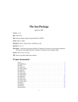
Figure 1-1. Configuration Diagram of V850 Simulator
Input from user
Debugger block
Simulator block
External parts GUI block
User-customized external
parts block (DLL file)
External parts
block
External parts user
open interface block
Instruction simulation block, peripheral simulation block, peripheral GUI block
Debugger block
Any directive from the user that causes any function to be executed by the simulator is
called a command. The debugger block provides an environment in which the user can
enter such commands via the keyboard or the mouse.
Peripheral GUI block
This block provides a setup environment that enables the user to easily set the desired
input information to a port via a window.
DLL
DLL stands for "Dynamic Link Library." DLLs are Windows modules that contain
executable code and data that can be accessed by functions within Windows
applications or other DLLs.
External parts GUI block
This block enables external part operations to be performed via a window.
External parts block
This is part of the external parts GUI block, which is used to control standard external
parts.
User-customized external parts block
This is part of the external parts GUI block, which is used for user-created external parts.
External parts user open interface
block
This is part of the external parts GUI block, which is used as an interface between the
external parts block and the user-customized external parts block.
14
User’s Manual U14873EJ2V0UM
CHAPTER 1 GENERAL
1.3
1.3.1
Environment
Development environment
The following describes the development environment under which users write programs according to this
manual's specifications in order to create DLL files.
Hardware environment: IBM PC/AT™ compatible
(CPU: Pentium™ 166 MHz or above is recommended)
Software environment:
Windows 98/Windows NT 4.0/Window 2000/Windows Me/Windows XP
Microsoft Visual C++ V5.00 or later
1.3.2
Operating environment
The operating environment of the simulator that loads and operates user-created files is described below.
Hardware environment: IBM PC/AT compatible
(CPU: Pentium 166 MHz or above is recommended)
Software environment:
Windows 98/Windows NT 4.0/Window 2000/Windows Me/Windows XP
User’s Manual U14873EJ2V0UM
15
CHAPTER 2 DOWNLOAD
This chapter describes the steps for downloading to the simulator user-customized parts that have been created as
described in Chapters 3 and 4.
Before user-customized external parts (DLL files) can be actually used, they must be loaded into the simulator.
To remove loaded user-customized external parts (DLL files), unload them from the simulator.
Use the Parts window to load and unload user-customized external parts (DLL files).
Figure 2-1. SM850 Simulator Parts Window
16
User’s Manual U14873EJ2V0UM
CHAPTER 2 DOWNLOAD
2.1
Download
Operation steps
(1) In the Parts window, select [Customize] menu→ [Load] from the menu bar to open the Open dialog box.
Figure 2-2. Open Dialog Box
(2) In the Open dialog box, select a customized external part DLL file, then click the <Open> button. The specified
DLL file is then loaded into the simulator. Once this has been done, the part created by the customization
function in the Parts window is pasted in the Parts window. If the part was customized via a user window, it is
displayed in a user window.
(a) Up to six user-customized external part DLLs can be loaded into the simulator.
(b) A user-customized external part DLL file that is downloaded to the simulator remains valid even after the
Parts window is closed. The next time the Parts window is opened, the same DLL file will be automatically
downloaded.
(c) The name of the loaded user-customized external part DLL file is added to the pull-down menu under
[Customize] menu of the Parts window.
(d) The user-customized external part that is displayed in the Parts window can be relocated. However, the
information about the relocation cannot be saved.
After relocation, if you have performed either the
following sets of operations, the location of each part is neither saved nor completed. Therefore, be sure
to locate each part again.
y If the status is saved to a project file (xxxx.prj) or to a file to which display information for the Parts
window is to be saved (xxxx.pnl), and then these files are read
y If the Parts window is closed while customized external part DLL information remains loaded, and then
the Parts window is opened again
2.2
Unload
Operation steps
(1) Select [Customize] menu → [Unload] from the menu bar in the Parts window.
(2) This unloads (removes) all of the customized external part DLLs that are currently loaded in the simulator.
Parts that have been created by the Parts window's customization function are deleted from the Parts window.
Also, if there are any programs that have been customized via a user window, the user window is closed.
User’s Manual U14873EJ2V0UM
17
CHAPTER 3 PROGRAMMING
3.1
Programming Configuration and Processing Flow
This chapter describes the basic programming used for customization via the Parts window and customization via
the user window.
3.1.1
Customization via Parts window
Configuration
The configuration includes user functions that are called only once after the DllMain function (required to create
DLL files) and the DLL files have been loaded.
Function references described in Chapter 4 must be included either in user functions or in functions subordinate
to user functions.
Processing flow
The simulator's external parts block is used to create parts based on the specified function's part information and
performs all simulation related to parts associated with the simulator's external parts block.
Figure 3-1 shows the relation between user-created DLL files and external parts in the simulator, as well as the
configuration of functions.
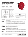
Figure 3-1. Programming Configuration and Processing Flow for Customization via Parts Window
User-customized file
UPusr.c
#include<Windows.h>
#include"uparts32.h"
External parts block
Called once after
UPusr.dll is loaded
External parts user
open I/F block
18
DllMain(.....){
:
}
Uparts_usr(){
UpPushBtm(...);
UpMtxLed(....);
:
}
User’s Manual U14873EJ2V0UM
CHAPTER 3 PROGRAMMING
3.1.2
Customization via user window
Configuration
The configuration includes the DllMain function (required to create DLL files), the created window's callback
functions, user functions, and simulation call functions that are called at a set interval during simulations.
User functions and their subordinate functions are used to report simulation call functions and the motor pin
names. The creation of parts and programming of I/O actions are done using the user-created window's callback
functions and simulation call functions.
Processing flow
Simulation of customized parts is performed as the simulator works with the external parts block using functions
that capture and set I/O information on pins and ports. The pin output information also can be redrawn (or
otherwise processed) by calling simulation call functions from the external parts block.
Figure 3-2 shows the relation between DLL files customized via a user-created window and external parts in the
simulator, as well as the configuration of functions.
User’s Manual U14873EJ2V0UM
19
CHAPTER 3 PROGRAMMING
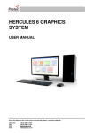
Figure 3-2. Programming Configuration and Processing Flow for Customization via User Window
User-customized file
UOusrwin.c
External part user open I/F is called
Called by external part
#include<Windows.h>
#include "uparts32.h"
unsigned long psw_reg;
DllMain(.....){
RegisterClass();
}
User window's
callback function
External parts block
Called once after
UOusrwin.dll is loaded
Called once each time a
simulation is executed
External parts
user open I/F block
Called when CPU
reset occurs
Called when saving to
project file
Called when reading from
project file
WindProc(HWND hwnd,.....){
switch(msg){
case WM_COMMON:
switch(wParam){
case
IDM_BTM1:
UpSetPin("p21",1,50);
:
}
case WM_DESTROY:
UpCloseUserWnd(hwnd);
:
}
}
Uparts_usrwin(){
int
i;
hwnd=CreateWindow(.......);
UpSetUserWnd(hwnd);
UpCallFuncName("Update_usrwin");
UpResetFuncName("Upsur_reset");
UpSaveProjName("UpSave_usrproj");
UpLoadProjName("UpLoad_usrproj");
i=UplnitPin("p21",HIGH);
:
}
Update_usrwin(unsigned long simtime){
val=UpGetPin("p32");
:
}
Upusr_reset(){
:
}
UpSave_usrproj(char *filename ){
WritePrivateProfileString("User Window",.....,filename);
:
}
UpLoad_usrproj(char *filename ){
GetPrivateProfileString("User DLL Window",.....,"filename);
:
}
20
User’s Manual U14873EJ2V0UM
CHAPTER 3 PROGRAMMING
3.2
3.2.1
1.
Steps in Creation of Customized Parts
Customization via Parts window
Program the external parts to be customized when creating a DLL file using Windows programming methods.
Be sure to include the file "uparts32.h" in this programming and add "uparts32.cpp" to the project.
2.
Use Windows programming methods to create a module definition (DEF) file
Note
, a make file, and, if necessary,
a resource file, then compile to create a user-created DLL file.
y When compiling, specify the option (/Zp1) for single-byte alignment of structure members.
y Specify "UP" as the first two characters in the name of the created DLL file.
y To operate the DLL file in an environment in which Microsoft Visual C++ is not installed, create the DLL file
using the released version.
3.
Enter the user-created DLL file name in the place for specifying the simulator's external parts customization
files (See 2.1 Download).
4.
In addition to the standard parts that are already displayed in the Parts window, the user-created customized
parts are displayed.
5.
Set the Parts window to location mode and locate the parts.
6.
Select [Save As...] from [File] menu of the Parts window and save the current status so that there will not be
any need to load the user-created DLL files when performing the next simulation.
3.2.2
1.
Customization via user window
Program the external parts to be customized when creating a DLL file using Windows programming methods.
Be sure to include the file "uparts32.h" in this programming and add "uparts32.cpp" to the project.
2.
Use Windows programming methods to create a module definition (DEF) file
Note
, a make file, and, if necessary,
a resource file, then compile to create a user-created DLL file.
y When compiling, specify the option (/Zp1) for single-byte alignment of structure members.
y Specify "UO" as the first two characters in the name of the created DLL file.
y To operate the DLL file in an environment in which Microsoft Visual C++ is not installed, create the DLL file
using the released version.
3.
Enter the user-created DLL file name in the place for specifying the simulator's external parts customization
files (See 2.1 Download).
4.
The window created by the user and the corresponding customized parts are displayed.
Note See 3.4 Module Definition (DEF) File.
User’s Manual U14873EJ2V0UM
21
CHAPTER 3 PROGRAMMING
Figure 3-3. Creation Flow
usr.def
uparts32.h
usr.c
Compile
UPusr.dll
UOusr.dll
Load
External parts
block
22
User’s Manual U14873EJ2V0UM
uparts32.cpp
CHAPTER 3 PROGRAMMING
3.3
Basic Rules
The basic rules for user programming of customized parts are described below.
3.3.1
User functions
User functions are main functions that are described by users.
(1) When a user-created DLL file is loaded to the simulator, it becomes a function that is called by the simulator.
(2) The function references described in Chapter 4 must be contained in user functions or functions that are
subordinate to user functions.
(3) User function names are function names in which the name of the user-created DLL file minus the first two
characters is added to "UParts_".
(4) The first two characters of the user-created DLL file name are fixed.
(a) Customization via Parts window
Always use "UP" as the first two characters of the user-created DLL file name.
Example: UPusr.dll → UParts_usr()
(b) Customization via user window
Always use "UO" as the first two characters of the user-created DLL file name.
Example: UOusr.dll → UParts_usr()
(5) Use void type with no parameters for user functions.
(6) Enter an EXPORTS declaration
Note
in the module definition file for user functions.
Note See 3.4.1 EXPORTS declaration.
3.3.2
External variables
When using external variables, always add "UP" to the start.
Example: int UPglobal
3.3.3
Function names
Function names are the names that are given to user-created external parts.
If you do not wish to use a function name as the part name, enter a NULL string as the parameter of the function
used to create the part.
3.3.4
Active high/low
The "active high/low" designation specifies the relation between a pin's value and its active state (when a part
connected to a pin is operating). If the function used to create a part includes a parameter for specifying "active
high/low," specify one of the following macros (the macros "HIGH" and "LOW" are defined in uparts32.h).
Operation using 1 (high): HIGH
Operation using 0 (low):
LOW
User’s Manual U14873EJ2V0UM
23
CHAPTER 3 PROGRAMMING
3.3.5
Pin names
Some of the parameters in functions used to create parts are for specifying pin names or port names. In such
cases, each pin name or port name is specified as a character string, and its name should be as described in the
target device's User's Manual. Specifications are not case-sensitive.
3.3.6
Include file , Source file
The include file "uparts32.h" and source file "uparts32.cpp" that are used for user customization are bundled in the
SM850 product package. Include "uparts32.h" and add "uparts32.cpp" to the project.
y "uparts32.h" contains descriptions of macro definitions for active high/low status, and IMPORTS declarations for
functions described in CHAPTER 4 FUNCTION REFERENCE.
y When compiling, be sure to set the include path in the directory where the file "uparts32.h" is located.
24
User’s Manual U14873EJ2V0UM
CHAPTER 3 PROGRAMMING
3.4
Module Definition (DEF) File
A module definition (DEF) file must be created to include the EXPORTS declaration, as described in the module
definition file for Windows programming.
The IMPORTS declaration is already included in the file "Uparts32.h" and therefore does not need to be considered.
3.4.1
EXPORTS declaration
Be sure to enter an EXPORTS declaration for user functions and simulation call functions.
You must also enter an EXPORTS declaration for functions used to read or save project files, for reset functions,
and some other functions.
Example: EXPORTS
UParts_usrwin
UPdata_usrwin
User’s Manual U14873EJ2V0UM
25
CHAPTER 4 FUNCTION REFERENCE
4.1
Customization via Parts window
The functions that can be called from within user functions and pasted into the Parts window to perform all
simulation processing are listed below.
These functions can be used to easily create parts simply by specifying pins and action information as parameters.
Note, however, that even if the user has created a window, all parts that are created by this function are still pasted
in the Parts window.
Table 4-1. Customization Functions Used in Parts Window
Function Name
Prototype
Page
Push-button function
UpPushBtm(pname, actype, btmname)
27
Toggle button function
UpTglBtm(pname, actype, btmname)
28
Group select button (exclusive push-button)
function
UpSelectBtm(gname, pnames, pnum, actype, btmnames)
29
Hold time setup function
UpSetPBtmtime(time)
31
LED function
UpLed(pname, actype, ledname, pictype)
32
LED function set per port
UpPortLed(portname, actype, ledname, pictype)
34
Matrix LED function
UpMtxLed(pnames1, pnames2, pnum1, pnum2, actype1, actype2)
35
DC motor function
UpDcMtr(pname, actype, mtrname)
36
Stepping motor function
UpStpingMtr(pnames, num, actype, reiji, step)
37
Vertical scroll bar analog input function
UpScaleInterAD(pname, adname)
38
Reference voltage value setup function
UpSetAVref(avref)
39
Bitmap setup function for button
UpSetBtmBmp(actbmp, nactbmp)
40
Bitmap setup function for LED
UpSetLedBmp(actbmp, nactbmp)
41
Bitmap setup function for DC motor
UpSetMtrBmp(actbmp, nactbmp)
42
LED picture setup function
UpSetLedPic(type, color)
43
Serial pin data input function
UpSerial_data(serpname, data, count, first, bitnum)
44
Window title function
UpPanelTitleName(title)
45
Bitmap display function
UpSetUsrBmp(bmpname)
46
Character string display function
UpWriteString(string)
47
26
User’s Manual U14873EJ2V0UM
CHAPTER 4 FUNCTION REFERENCE
Push-button function
void
UpPushBtm(pname, actype, btmname)
char
*pname ;
/* Pin name */
int
actype ;
/* Active high/low */
char
*btmname ;
/* Function name */
[Function]
This function creates one push-button. A push-button is a button icon that sets and holds input status for a
specified hold time only after the button has been clicked. The hold time is set using the hold time setup function
UpSetPBtmtime().
The time set in UpSetPBtmtime described before this function is assumed as the hold time. If a hold time is not set,
the default value 0.5 ms is used.
[Parameters]
pname
Specifies the pin name as a character string.
actype
Specifies a value to be input using a push-button. Specify HIGH to enter a "1" (high value) or
LOW to enter a "0" (low value).
btmname
Specifies the name of the push-button function. Since this function name is displayed on the
button, the character string is limited to 16 single-byte characters.
[Return value]
None
[Example]
UpSetPBtmtime(50) ;
UpPushBtm("p20", HIGH, "START") ;
UpPushBtm("p20", LOW, "STOP") ;
Figure 4-1. Push-Buttons
User’s Manual U14873EJ2V0UM
27
CHAPTER 4 FUNCTION REFERENCE
Toggle button function
void
UpTglBtm(pname, actype, btmname)
char
*pname ;
/* Pin name */
int
actype ;
/* Active high/low */
char
*btmname ;
/* Function name */
[Function]
This function creates one toggle button. When clicked, a toggle button sets and holds input status until the same
button is clicked again.
This button's initial mode is inactive mode. The first time this button is clicked, the value specified by the parameter
actype is input.
[Parameters]
pname
Specifies the pin name as a character string.
actype
Specifies a value to be input using the toggle button. Specify HIGH to enter a "1" (high value)
or LOW to enter a "0" (low value).
btmname
Specifies the name of the toggle button function. Since this function name is displayed on the
button, the character string is limited to 16 single-byte characters.
[Return value]
None
[Example]
UpTglBtm("p22", HIGH, "START") ;
UpTglBtm("p23", LOW, "STOP") ;
Figure 4-2. Toggle Buttons
28
User’s Manual U14873EJ2V0UM
CHAPTER 4 FUNCTION REFERENCE
Group select button (exclusive push-button) function
void
UpSelectBtm(gname, pnames, pnum, actype, btmnames)
char
*gname ;
char
**pnames ;
/* Pin name */
int
pnum ;
/* Number of buttons */
int
actype ;
/* Active high/low */
char
**btmnames ;
/* Function name */
/* Group name */
[Function]
Several buttons can be grouped together as exclusive buttons.
Clicking one of the group of buttons that is
enclosed in a frame enters an active value for the clicked button only.
The entered value remains in effect until another button is clicked. In other words, there can be only one active
button at a time within the button group.
[Parameters]
gname
Specifies the name assigned to the group. This group name is shown at the top of the group
select buttons.
pnames
Specifies pin names (character strings) for each button.
pnum
Specifies the number of buttons.
actype
Specifies the value entered by clicking a group select button. Specify HIGH to enter a "1"
(high value) or LOW to enter a "0" (low value). The active status for all group buttons is the
same.
btmnames
Specifies the names assigned to individual buttons. Since this function name is displayed on
the button, the character string is limited to 10 single-byte characters.
[Return value]
None
User’s Manual U14873EJ2V0UM
29
CHAPTER 4 FUNCTION REFERENCE
[Example]
static char *sizePin[4] =
{"p30", "p31", "p32", "p33"} ;
static char *sizeName[4] = {"B5", "A4", "B4", "A3"} ;
UpSelectBtm("Size", sizePin, 4, HIGH, sizeName) ;
Figure 4-3. Group Select Buttons
30
User’s Manual U14873EJ2V0UM
CHAPTER 4 FUNCTION REFERENCE
Hold time setup function
void
UpSetPBtmtime(time)
char
*time ;
/* Hold time */
[Function]
This function specifies the hold time for a push-button.
[Parameter]
time
Sets a hold time character string. The unit for this setting is ms (milliseconds).
The range of settings is 0.001 to 999 ms.
[Return value]
None
[Example]
UpSetPBtmtime("0.2") ;
User’s Manual U14873EJ2V0UM
31
CHAPTER 4 FUNCTION REFERENCE
LED function
void
UpLed(pname, actype, ledname, pictype)
char
*pname ;
/* Pin name */
int
actype ;
/* Active high/low */
char
*ledname ;
/* Function name */
char
pictype ;
/* Picture type */
[Function]
This function creates one LED.
When the specified pin's status is active, an active bitmap (or color picture) is displayed. When the pin's status is
inactive, an inactive bitmap (or colorless picture) is displayed.
[Parameters]
pname
Specifies the pin name as a character string.
actype
Specifies the value to be displayed on the LED. Specify "1" for active high or "0" for active
low.
ledname
Specifies the LED's function name. This function name is shown on the LED. There is no
limit on the number of characters.
pictype
Specifies the type of picture (or bitmap image) used in the LED display.
If 1: The default bitmap type is a light bulb-type bitmap image. However, any bitmap
specified by the UpSetLedBmp() function is displayed instead of the default bitmap.
If 0: The default picture type is a rectangular picture.
Any picture specified by the
UpSetLedPic() function is displayed instead of the default picture.
[Return value]
None
32
User’s Manual U14873EJ2V0UM
CHAPTER 4 FUNCTION REFERENCE
[Example]
UpLed("p40", LOW, "Reserved", 1) ;
UpLed("p21", HIGH, "Power", 1) ;
Figure 4-4. Bitmap Images for Inactive LED (Left) and Active LED (Right)
UpLed("p41", LOW, "L", 0) ;
UpLed("p22", HIGH, "H", 0) ;
Figure 4-5. Pictures for Inactive LED (Left) and Active LED (Right)
User’s Manual U14873EJ2V0UM
33
CHAPTER 4 FUNCTION REFERENCE
LED function set per port
void
UpPortLed(portname, actype, ledname, pictype)
char
*portname ;
/* Port name */
unsigned char
actype ;
/* Active high/low */
char
*ledname ;
/* Function name */
char
pictype ;
/* Picture type */
[Function]
This function creates a set of LEDs corresponding to pins assigned to a particular port (eight LEDs make one set).
An active bitmap (or color picture) is displayed for each pin that is active and an inactive bitmap (or colorless
picture) is displayed for each pin that is inactive.
[Parameters]
portname
Specifies the port name as a character string.
actype
Specifies the value for displaying an active bitmap. Specify "1" if a value of "1" (high) is active
or specify "0" if a value of "0" (low) is active.
The 8-bit data that sets the status of eight LEDs is specified bitwise. The port's lowest pin is
specified as the LSB, then the other seven bits are specified in order from LSB to MSB.
ledname
Specifies a name to be assigned to an LED. This function name is shown below the bitmap.
There is no limit on the number of characters.
pictype
Specifies the picture type used in the LED display. "1" specifies bitmap and "0" specifies a
rectangular picture.
[Return value]
None
[Example]
UpPortLed("p3",0xfc,"Number",1) ;
Figure 4-6. LED Function Set Per Port
Left pin name
is not shown.
34
User’s Manual U14873EJ2V0UM
CHAPTER 4 FUNCTION REFERENCE
Matrix LED function
void
UpMtxLed(pnames1, pnames2, pnum1, pnum2, actype1, actype2)
char
**pnames1 ;
/* Output 1 pin names */
char
**pnames2 ;
/* Output 2 pin names */
int
pnum1 ;
/* Output 1 pin number */
int
pnum2 ;
/* Output 2 pin number */
int
actype1 ;
/* Active high/low for output 1*/
int
actype2 ;
/* Active high/low for output 2*/
[Function]
This function creates an LED on a matrix. When any intersection is active on the matrix of the output 1 and output
2 pins, a matrix LED showing the active bitmap is created (the active bitmap is fixed and cannot be specified).
[Parameters]
pnames1
Specifies the output 1 pin names (character strings) for all output 1 pins only.
pnames2
Specifies the output 2 pin names (character strings) for all output 2 pins only.
pnum1
Specifies the number of output 1 pins.
pnum2
Specifies the number of output 2 pins.
actype1
Specifies the value for displaying output 1. Specify "1" for active high status or "0" for active
low status. The active status for output 1 is the same for all output 1 pins.
actype2
Specifies the value for displaying output 2. Specify "HIGH" for active high status or "LOW" for
active low status. The active status for output 2 is the same for all output 2 pins.
[Return value]
None
[Example]
static char *out1[4] = {"p30", "p31", "p32", "p33"} ;
static char *out2[4] = {"p24", "p25", "p26", "p27"} ;
UpMtxLed((char *)out1, (char *)out2, 4, 4, HIGH, HIGH) ;
Figure 4-7. Matrix LED Function
Pin names are not shown
User’s Manual U14873EJ2V0UM
35
CHAPTER 4 FUNCTION REFERENCE
DC motor function
void
UpDcMtr(pname, actype, mtrname)
char
*pname ;
/* Pin name */
int
actype ;
/* Active high/low */
char
*mtrname ;
/* Function name */
[Function]
This function creates a DC motor icon. An active bitmap is displayed when the specified pin becomes active, and
the inactive bitmap is displayed when the specified pin is inactive.
This function also displays the total active time that has elapsed since the start of a simulation. The displayed time
is based on the main system clock. When a reset occurs or when the elapsed time value exceeds a 10-digit
decimal value, the displayed time is cleared to zero.
[Parameters]
pname
Specifies the pin name as a character string.
actype
Specifies the status when the motor is displayed as active. Specify HIGH for active high
status or LOW for active low status.
mtrname
Specifies the DC motor function's name. This function name is shown under the motor icon.
[Return value]
None
[Example]
UpDcMtr("p41", HIGH, "Motor") ;
Figure 4-8. Active LED (Left) and Inactive LED (Right)
36
User’s Manual U14873EJ2V0UM
CHAPTER 4 FUNCTION REFERENCE
Stepping motor function
void
UpStpingMtr(pnames, num, actype, reiji, step)
char
**pnames ;
/* Pin names */
int
num ;
/* Number of pins per channel */
int
actype ;
/* Active high/low */
char
reiji ;
/* Excitation method */
short
step ;
/* Minimum step angle */
[Function]
This function creates a stepping motor that is operated via several pins.
The motor is displayed according to its direction of rotation, with the rotation speed and step angles.
[Parameters]
pname
Specifies pin names (character strings) for all pins.
num
Specifies the number of pins per channel (4 or 8).
actype
Specifies the status when the motor is displayed as active. Specify HIGH for active high
status or LOW for active low status. The active status is the same for all pins.
reiji
Specifies the excitation method. Set "0" for single phase or "1" for single/dual phase.
step
Specifies an integer fraction of 360 as the minimum step angle.
[Return value]
None
[Remarks]
Once operation of this function is started, the first value other than zero that is output to a connected pin is taken as
the initial value. At that point, the stepping motor is shown as stopped (not rotating).
[Example]
char *mtrpin[4] = {"p00", "p01", "p02", "p03"} ;
UpStpingMtr((char *)mtrpin, 4, HIGH, 1, 10) ;
Figure 4-9. Stepping Motor
Number of positive revolutions
Number of negative revolutions
Rotation angle
mark and yellow motor means negative rotation
Green motor means stopped
mark and red motor means positive rotation
User’s Manual U14873EJ2V0UM
37
CHAPTER 4 FUNCTION REFERENCE
Vertical scroll bar analog input function
void
UpScaleInterAD(pname, adname)
char
*pname ;
/* Pin name */
char
*adname ;
/* Function name */
[Function]
This function creates an analog input part for a vertical scroll bar.
Move the scroll button and right-click the mouse over the scroll bar to enable input of analog data. Input values are
used to create a part that is shown in red.
[Parameters]
pname
Specifies the name of analog input pin as a character string.
adname
Specifies the function name of the scroll bar-type input part. This function name is displayed
above the scroll bar-type input part and there is no limit on the number of characters.
[Return value]
None
[Remarks]
The scroll bar's operating range is determined either by settings made via the reference voltage value setup
function UpSetAVref() or by the reference voltage value settings made via the Standard Level Gauge Pin Setting
Note
dialog box
. If neither of these settings have been made, the default value of 5.0 V is used.
Note See CHAPTER 7 WINDOW REFERENCE in the SM850 V2.50 System Simulator Operation (U16218E).
[Example]
UpScaleInterAD("ani1", "Voltage") ;
Figure 4-10. Vertical Scroll Bar Analog Input
38
User’s Manual U14873EJ2V0UM
CHAPTER 4 FUNCTION REFERENCE
Reference voltage value setup function
void
UpSetAVref(avref)
char
*avref ;
/* Reference voltage value */
[Function]
This function sets the reference voltage value for the A/D converter.
This reference voltage value is used to determine the operating range for an analog input part.
Any setting that is within the range for operating power supply voltage (see the User's Manual of each device) can
be set.
Values can be set as precisely as the first decimal place, but subsequent decimal places are rounded off.
[Parameter]
avref
Specifies the reference voltage value as a character string.
[Return value]
None
[Remarks]
If this function or the standard setting is not set, the analog input part will operate using the default voltage value of
5.0 V.
[Example]
UpSetAVref("3.5") ;
User’s Manual U14873EJ2V0UM
39
CHAPTER 4 FUNCTION REFERENCE
Bitmap setup function for button
void
UpSetBtmBmp(actbmp, nactbmp)
char
*actbmp ;
/* Active bitmap name character string */
char
*nactbmp ;
/* Inactive bitmap name character string */
[Function]
This function sets the bitmap for a button. A button display can be changed by entering this function immediately
before the target button's function. The same bitmap will be displayed until it is set again by this function. The
bitmap file should be stored in the same directory as the simulator or its name should be specified with the full path.
[Parameters]
actbmp
Specifies a character string for the bitmap file name displayed when active.
nactbmp
Specifies a character string for the bitmap file name displayed when inactive.
[Return value]
None
[Remarks]
If a button function is described without describing this function first, the standard button's bitmap is displayed (see
the image shown in Figure 4-1). The button name is not shown when setting this function.
[Example]
UpSetBtmBmp("on.bmp", "off.bmp") ;
UpPushBtm("p21", LOW, "START") ;
40
User’s Manual U14873EJ2V0UM
CHAPTER 4 FUNCTION REFERENCE
Bitmap setup function for LED
void
UpSetLedBmp(actbmp, nactbmp)
char
*actbmp ;
/* Active bitmap name character string */
char
*nactbmp ;
/* Inactive bitmap name character string */
[Function]
This function sets the bitmap for an LED. An LED display can be changed by entering this function immediately
before the target LED's function. This function is valid only if the bitmap has been specified by an LED function.
The same bitmap will be displayed until it is set again by this function. The bitmap file should be stored in the
same directory as the simulator or its name should be specified with the full path.
[Parameters]
actbmp
Specifies a character string for the bitmap file name displayed when active.
nactbmp
Specifies a character string for the bitmap file name displayed when inactive.
[Return value]
None
[Remarks]
If an LED function is described without describing this function first, the standard LED's bitmap is displayed (see
the image shown in Figure 4-4).
[Example]
UpSetLedBmp("lighton.bmp", "lightoff.bmp") ;
UpLed("p31", HIGH, "Power", 1) ;
User’s Manual U14873EJ2V0UM
41
CHAPTER 4 FUNCTION REFERENCE
Bitmap setup function for DC motor
void
UpSetMtrBmp(actbmp, nactbmp)
char
*actbmp ;
/* Active bitmap name character string */
char
*nactbmp ;
/* Inactive bitmap name character string */
[Function]
This function sets the bitmap for a DC motor. A DC motor display can be changed by entering this function
immediately before the target DC motor's function. The same bitmap will be displayed until it is set again by this
function. The bitmap file should be stored in the same directory as the simulator or its name should be specified
with the full path.
[Parameters]
actbmp
Specifies a character string for the bitmap file name displayed when active.
nactbmp
Specifies a character string for the bitmap file name displayed when inactive.
[Return value]
None
[Remarks]
If a DC motor function is described without describing this function first, the standard DC motor's bitmap is
displayed (see the image shown in Figure 4-8).
[Example]
UpSetMtrBmp("trun.bmp", "stop.bmp") ;
UpDcMtr("p32", HIGH, "Motor") ;
42
User’s Manual U14873EJ2V0UM
CHAPTER 4 FUNCTION REFERENCE
LED picture setup function
void
UpSetLedPic(type, color)
char
type ;
/* Picture type */
char
color ;
/* Picture fill color when active */
[Function]
This function sets the type of picture and fill color (when active) to be used in an LED display. An LED display can
be changed by entering this function immediately before the target LED's function. This function is valid only if a
picture has been specified by an LED function. The same picture will be displayed until it is set again by this
function.
[Parameters]
type
Specifies the type of picture (macro is defined in uparts32.h).
Macro PIC_RECT: Rectangle
Macro PIC_ELL:
color
Ellipse
Specifies fill color when active (macro is defined in uparts32.h).
Macro PIC_RED:
Red
Macro PIC_YELLOW: Yellow
Macro PIC_GREEN:
Green
[Return value]
None
[Example]
UpSetLedPic(PIC_RECT, PIC_GREEN) ;
UpLed("p32", HIGH, "Test", 0) ;
User’s Manual U14873EJ2V0UM
43
CHAPTER 4 FUNCTION REFERENCE
Serial pin data input function
void
UpSerial_data(serpname, data, count, first, bitnum)
char
*serpname ;
/* Serial pin name character string */
unsigned short
*data ;
/* Pointer to data array */
unsigned short
count ;
/* Number of data arrays */
char
first ;
/* First bit (MSB or LSB)*/
char
bitnum ;
/* Number of bits in transfer data */
[Function]
This function sets values in order starting from the specified first data bit, using the number of bits in the data
transferred to the serial pin as one unit.
[Parameters]
serpname
Specifies the character string for the name of the serial data input pin.
data
Specifies a pointer to an array in which the value set to the serial data input pin has been
stored in units consisting of the number of transfer data bits.
count
Specifies the number of arrays in which values set to the serial data input pin have been
stored in units consisting of the number of transfer data bits.
first
Specifies whether data equivalent to the number of bits in the transfer data will be set
sequentially with the MSB first or the LSB first. "1" is specified to set sequentially with the
MSB first and "0" is specified to set sequentially with the LSB first.
bitnum
Specifies the number of bits in the transfer data.
When using UART (Universal Asynchronous Receiver/Transmitter), the start bit, parity bit,
and stop bit are included in the data and data bit count.
[Return value]
None
[Example]
To set 8-bit data sequentially from LSB first to serial pin SER1:
unsigned short data[3] = {0xff, 0xa0, 0x3b} ;
Upserial_data("SER1", data, 3, 0, 8) ;
The data is input to SER1 as shown below.
← 111111110000010111011100
44
User’s Manual U14873EJ2V0UM
CHAPTER 4 FUNCTION REFERENCE
Window title function
void
UpPanelTitleName(title)
char
*title ;
/* Title name */
[Function]
This function displays a name in the title bar of the Parts window.
[Parameter]
title
Specifies the character string for the name to be displayed in the title bar of the Parts window.
[Return value]
None
[Example]
UpPanelTitleName("System for printer") ;
User’s Manual U14873EJ2V0UM
45
CHAPTER 4 FUNCTION REFERENCE
Bitmap display function
void
UpSetUsrBmp(bmpname)
char
*bmpname ;
/* Bitmap file name */
[Function]
This function displays a bitmap that is always displayed, without any relation to simulations.
The bitmap is displayed to the right of the part that is at the bottom right in the set of currently displayed parts. If
there is not enough room in the window to display the bitmap to the right of the bottom right part, it is displayed
below the bottom right part.
[Parameter]
bmpname
Specifies a character string as the bitmap file name. The bitmap file should be stored in the
same directory as the simulator or its name should be specified with the full path.
[Return value]
None
[Example]
UpSetUsrBmp("printer.bmp") ;
46
User’s Manual U14873EJ2V0UM
CHAPTER 4 FUNCTION REFERENCE
Character string display function
void
UpWriteString(string)
char
*string ;
/* Character string to be displayed */
[Function]
This function displays a character string.
The character string is displayed to the right of the part that is at the bottom right in the set of currently displayed
parts. If there is not enough room in the window to display the character string to the right of the bottom right part,
it is displayed below the bottom right part.
[Parameter]
string
Specifies the character string to be displayed.
[Return value]
None
[Example]
UpWriteString("Power") ;
User’s Manual U14873EJ2V0UM
47
CHAPTER 4 FUNCTION REFERENCE
4.2
Customization via User Window
The following functions are provided to enable the user to freely customize user-created windows and parts. The
handle notification function for user windows can be used to enable processing of windows and input from user parts,
and the simulation call function can be used to perform output display processing to user parts.
Table 4-2. Customization Functions Used in User Window
Function Name
Prototype
Page
Window handle notification function
UpSetUserWnd(hUwnd)
49
Window close function
UpCloseUserWnd(hwnd)
50
Simulation call function
UpCallFuncName(fname)
51
Motor pin notification function
UpInitMtrPin(pname,actype)
52
Stepping motor notification function
UpInitStpingMtr(pname, num, actype, reiji, step)
53
Pin active value notification function
UpInitPin(pname, actype)
54
Port active value notification function
UpInitPort(portname, actype)
55
AD input pin notification function
UpInitAD(pname)
56
Project file read function name notification function
UpLoadProjName(funcname)
57
Project file save function name notification
function
UpSaveProjName(funcname)
58
Reset function name notification function
UpResetFuncName(funcname)
59
Pin value capture function
UpGetPin(pname, val)
60
Port data capture function
UpGetPort(portname, data)
61
DA output pin value capture function
UpGetDA(pname, val)
62
Memory area data capture function
UpGetMem(addr, data)
63
DC motor active time clear function
UpClrMtrAcClk(pname)
64
Stepping motor information capture function
UpGetStpingMtr(pnames, num, posrev, negrev, angle)
65
Value setting function for pins
UpSetPin(pname, val, time)
66
Data setting function for ports
UpSetPort(portname, data, time)
67
Value setting function for AD input pin
UpSetAD(pname, val)
68
Data setting function for memory area
UpSetMem(addr, data)
69
Active time notification function for motor
UpGetMtrAcClk(pname, val, actime)
70
Time conversion notification for one main system
clock pulse
UpSimtimeSec(void)
71
Function for transmitting packets from HOST using
USB function
UpSetUSBPack(total, total_bit, data)
72
Function for receiving packets from Function using
USB function
UpGetUSBPack(total, data)
73
Function for transmitting signals from HOST using
USB function
UpSetUSBSig(sig)
74
Function for receiving signals from Function using
USB function
UpGetUSBSig(sig)
75
48
User’s Manual U14873EJ2V0UM
CHAPTER 4 FUNCTION REFERENCE
Window handle notification function
void
UpSetUserWnd(hUwnd)
HANDLE
hUwnd ;
/* Handle of user window */
[Function]
This function notifies the simulator of a user-created window handle.
The user should describe this function immediately after creating a window.
[Parameter]
hUwnd
Handle of a user-created window
[Return value]
None
[Example]
HWND
hwnd ;
hwnd = CreateWindow(........) ;
UpSetUserWnd(hwnd) ;
User’s Manual U14873EJ2V0UM
49
CHAPTER 4 FUNCTION REFERENCE
Window close function
void
UpCloseUserWnd(hwnd)
HWND
hwnd ;
/* Handle of window to be closed */
[Function]
This function notifies the simulator that a user-created window is being closed.
This function is described with the user-created window callback function's message WM_DESTROY.
[Parameter]
hwnd
Handle of user-created window to be closed
[Return value]
None
[Example]
WM_DESTROY:
:
:
UpCloseUserWnd(hwnd) ;
50
User’s Manual U14873EJ2V0UM
CHAPTER 4 FUNCTION REFERENCE
Simulation call function
void
UpCallFuncName(fname)
char
*fname ;
/* Simulation call function name */
[Function]
This function reports the name of the function that is called from the simulator at a specified interval
Note
during
simulation.
This function must be described within the user function UParts_xxx().
Note This function is called once per command execution.
[Parameter]
fname
Specifies the name of the function called from the simulator.
[Return value]
None
[Remarks]
The simulation call function should be specified as follows in the function specifications.
The simulation's execution time is received via an unsigned long type parameter.
The simulation's execution time is time that has elapsed since the previous function call, and its measurement unit
is the main system clock.
Be sure to enter an EXPORTS declaration (see 3.4.1 EXPORTS declaration) in a module definition file for the
simulation call function.
void Update_usrwin(unsigned long simtime)
[Example]
UpCallFuncName("Update_usrwin") ;
User’s Manual U14873EJ2V0UM
51
CHAPTER 4 FUNCTION REFERENCE
Motor pin notification function
void
UpInitMtrPin(pname, actype)
char
*pname ;
/* Pin name */
int
actype ;
/* Active high/low */
[Function]
This function reports the pin name specified for the motor to capture the motor value and active time via the active
time notification function for motor.
When using the motor pin, this function must be described within the user function UParts_xxx().
When not using the motor pin, there is no need to describe this function.
[Parameters]
pname
Specifies a character string for the name of the pin connected to the motor.
actype
Specifies that the motor is in active mode. Specify HIGH for active high status or LOW for
active low status.
[Return value]
None
[Remarks]
Unless notification is already included in the user function, even if the information is captured by the active time
notification function for motor UpGetMtrAcClk() during a simulation, the captured value is not guaranteed.
[Example]
UpInitMtrPin("p41", HIGH)
52
User’s Manual U14873EJ2V0UM
CHAPTER 4 FUNCTION REFERENCE
Stepping motor notification function
int
UpInitStpingMtr(pnames, num, actype, reiji, step)
char
**pnames ;
/* Pin name */
int
num ;
/* Number of pins per channel */
int
actype ;
/* Active high/low */
char
reiji ;
/* Excitation method */
short
step ;
/* Minimum step angle */
[Function]
This function connects a stepping motor that is operated via several pins to the specified pin.
When using the stepping motor, this function must be described within the user function UParts_xxx(). When not
using the stepping motor, there is no need to describe this function.
[Parameters]
pnames
Specifies pin names (character strings) for all pins.
num
Specifies the number of pins per channel (4 or 8).
actype
Specifies the status when the motor is displayed as active. Specify HIGH for active high
status or LOW for active low status. The active status is the same for all pins.
reiji
Specifies the excitation method. Set "0" for single phase or "1" for single/dual phase.
step
Specifies an integer fraction of 360 as the minimum step angle.
[Return value]
If set correctly:
1
If not set correctly: 0
[Example]
char *mtrpin[4] = {"p00", "p01", "p02"," p03"} ;
UpInitStpingMtr((char *)mtrpin, 4, HIGH, 1, 10) ;
User’s Manual U14873EJ2V0UM
53
CHAPTER 4 FUNCTION REFERENCE
Pin active value notification function
int
UpInitPin(pname, actype)
char
*pname ;
/* Pin name */
int
actype ;
/* Active value of pin */
[Function]
This function sets the active mode value for one pin.
When there is a value to be input for a pin, this function must be described within the user function UParts_xxx().
When there is no value to be input for a pin, there is no need to describe this function.
[Parameters]
pname
Specifies the pin name as a character string.
actype
Specifies the active value of a pin. Specify HIGH for active high status or LOW for active low
status.
[Return value]
If pin's active value was set correctly:
1
If pin's active value was not set correctly: 0
[Example]
When set to operate when pin P46 is active high (when input value = 1):
int ret ;
ret=UpInitPin(“P46”, HIGH) ;
54
User’s Manual U14873EJ2V0UM
CHAPTER 4 FUNCTION REFERENCE
Port active value notification function
int
UpInitPort(portname, actype)
char
*portname ;
/* Port name */
unsigned char
actype ;
/* Active value of port */
[Function]
This function sets the active mode value for one port.
When there is a value to be input for a port, this function must be described within the user function UParts_xxx().
When there is no value to be input for a port, there is no need to describe this function.
[Parameters]
portname
Specifies the port name as a character string.
actype
Specifies the active value for each pin of a port.
Specify "1" for port pins that have active high status or "0" for port pins that have active low
status.
Values are specified bitwise for 8 bits, starting from the port's lowest pin as the LSB.
[Return value]
If port's active value was set correctly:
1
If port's active value was not set correctly: 0
[Example]
When port 4's pins P40 and P41 are set as active high and pins P42 to P47 are set as active low:
int ret ;
ret=UpInitPort(“P4”, 0x03) ;
When port 2's pin P27 only is set as active high and pins P20 to P26 are set as active low:
int ret ;
ret=UpInitPort(“P2”, 0x80) ;
User’s Manual U14873EJ2V0UM
55
CHAPTER 4 FUNCTION REFERENCE
AD input pin notification function
int
UpInitAD(pname)
char
*pname ;
/* AD input pin name */
[Function]
This function notifies the simulator of the AD input pin used to input a value from the user open interface function.
If UpSetAD() includes a value to be input to the AD input pin, this function must be described within the user
function UParts_xxx(). When the user open interface function does not include a value to be input to the AD input
pin, there is no need to describe this function.
[Parameter]
pname
Specifies the AD input pin name as a character string.
[Return value]
Normal end:
1
Abnormal end: 0 (if the AD input pin does not exist in a device used in the current simulation)
[Example]
UpInitAD(“ANI0") ;
56
User’s Manual U14873EJ2V0UM
CHAPTER 4 FUNCTION REFERENCE
Project file read function name notification function
int
UpLoadProjName(funcname)
char
*funcname ;
/* Project file read function name */
[Function]
When the simulator's project file is being read, this function reports the name of the function that simultaneously
reads the information in the user window from the project file.
This function must be described within the user function UParts_xxx().
[Parameter]
funcname
Specifies the name of the function that reads the project file that has been called from the
simulator.
[Return value]
None
[Remarks]
The project file read function's specifications are as follows.
y The project file name character string is received via the char * type parameter.
y User window information is also read from the file named by the project file name that was received via the
parameter. At that time, select either the GetPrivateProfileString or GetPrivateProfileInt function for the library
used with the read operation.
y The section name used by the user is "User DLL Window".
y An EXPORTS declaration is required in a module definition file for the project file read function.
void UpLoad_usrproj(char *filename)
[Example]
UpLoadProjName(“UpLoad_usrproj”) ;
User’s Manual U14873EJ2V0UM
57
CHAPTER 4 FUNCTION REFERENCE
Project file save function name notification function
int
UpSaveProjName(funcname)
char
*funcname ;
/* Project file save function name */
[Function]
When the simulator's project file is being saved, this function reports the name of the function that simultaneously
saves the information in the user window to the project file.
This function must be described within the user function UParts_xxx().
[Parameter]
funcname
Specifies the name of the function that saves the project file that has been called from the
simulator.
[Return value]
None
[Remarks]
The project file save function's specifications are as follows.
y The project file name character string is received via the char * type parameter.
y User window information is also written to the file named by the project file name that was received via the
parameter. At that time, select the WritePrivateProfileString function for the library used with the write operation.
y The section name used by the user is "User DLL Window".
y An EXPORTS declaration is required in a module definition file for the project file save function.
void UpSave_usrproj(char *filename)
[Example]
UpSaveProjName(“UpSave_usrproj”) ;
58
User’s Manual U14873EJ2V0UM
CHAPTER 4 FUNCTION REFERENCE
Reset function name notification function
int
UpResetFuncName(funcname)
char
*funcname ;
/* Reset function name */
[Function]
When a CPU reset is called by the simulator, this function reports the function name that is used for the user
window's reset processing.
This function must be described within the user function UParts_xxx().
[Parameter]
funcname
Specifies the name of the reset function called by the simulator.
[Return value]
None
[Remarks]
The reset function's specifications are as follows.
y It is a void type function since it has no parameters.
y An EXPORTS declaration is required in a module definition file for the reset function.
void Upreset_usrwin(void)
[Example]
UpResetFunName(“Upreset_usrwin”) ;
User’s Manual U14873EJ2V0UM
59
CHAPTER 4 FUNCTION REFERENCE
Pin value capture function
int
UpGetPin(pname, val)
char
*pname ;
/* Pin name */
char
*val ;
/* Pointer to area where pin value is stored */
[Function]
This function captures the value for one pin.
[Parameters]
pname
Specifies the pin name as a character string.
val
Specifies a pointer to the area where the pin value is stored.
[Return value]
If pin value was successfully captured:
If pin value was not successfully captured
1
Note
:0
Note "0" is also returned if the pin value is undefined.
[Example]
char val ;
int
ret ;
ret = UpGetPin(“p46", &val) ;
60
User’s Manual U14873EJ2V0UM
CHAPTER 4 FUNCTION REFERENCE
Port data capture function
int
UpGetPort(portname, data)
char
*portname ;
/* Port name */
unsigned char
*data ;
/* Pointer to area where port data is stored */
[Function]
This function captures port data.
[Parameters]
portname
Specifies the port name as a character string.
data
Specifies a pointer to the area where the port data is stored.
[Return value]
If port data was successfully captured:
If port data was not successfully captured
1
Note
:0
Note "0" is also returned if the port values include any undefined values.
[Example]
unsigned char data ;
int ret ;
ret = UpGetPort(“p4", (unsigned char *)&data) ;
User’s Manual U14873EJ2V0UM
61
CHAPTER 4 FUNCTION REFERENCE
DA output pin value capture function
int
UpGetDA(pname, val)
char
*pname ;
/* DA output pin name */
unsigned short
*val ;
/* DA output value */
[Function]
This function sets the value of the DA output pin.
[Parameters]
pname
Specifies the DA output pin name as a character string.
val
Specifies a pointer to the area where the value of the DA output pin is stored.
[Return value]
Normal end:
Abnormal end
1
Note
:0
Note "0" is also returned if the value of the DA output pin is undefined.
[Example]
unsigned short daval ;
UpGetDA(“ANO0", &daval) ;
62
User’s Manual U14873EJ2V0UM
CHAPTER 4 FUNCTION REFERENCE
Memory area data capture function
int
UpGetMem(addr, data)
unsigned long
addr ;
/* Address */
unsigned char
*data ;
/* Data storage area */
[Function]
This function captures the data in the memory area.
[Parameters]
addr
Specifies an address in the memory area to be captured.
data
Specifies the data storage area.
[Return value]
If data was successfully captured:
1
If data was not successfully captured: 0
[Example]
unsigned char data ;
int ret ;
ret = UpGetMem(0xffe000, (unsigned char *)&data) ;
User’s Manual U14873EJ2V0UM
63
CHAPTER 4 FUNCTION REFERENCE
DC motor active time clear function
void
UpClrMtrAcClk(pname)
char
*pname ;
/* Pin name */
[Function]
This function zero-clears the active time of the specified motor-connected pin.
[Parameter]
pname
Specifies the motor-connected pin name as a character string.
[Return value]
None
[Remarks]
When using this function, call the motor pin notification function UpInitMtrPin() from within a user function so that
the pin name is reported in advance.
[Example]
UpClrMtrAcClk(“p41") ;
64
User’s Manual U14873EJ2V0UM
CHAPTER 4 FUNCTION REFERENCE
Stepping motor information capture function
int
UpGetStpingMtr(pnames, num, posrev, negrev, angle)
char
**pnames ;
/* Pin names */
int
num ;
/* Number of pins per channel (specify 4 or 8) */
unsigned long
*posrev ;
/* Area for storing the number of positive revolutions */
unsigned long
*negrev ;
/* Area for storing the number of negative revolutions */
unsigned long
*angle ;
/* Area for storing angle */
[Function]
This function captures the number of positive/negative revolutions and current angle of the stepping motor that is
connected to the pin names previously reported by the stepping motor notification function UpInitStpingMtr.
[Parameters]
pnames
Specifies pin names (character strings) for all pins.
num
Specifies the number of pins per channel (4 or 8).
posrev
Specifies the area where the number of positive revolutions is stored.
negrev
Specifies the area where the number of negative revolutions is stored.
angle
Specifies the area where the angle is stored.
[Return value]
If successfully captured:
1
If not successfully captured: 0
[Example]
char *mtrpin[4] = {"p00", "p01", "p02", "p03"} ;
unsigned long posrev ;
unsigned long negrev ;
unsigned long angle ;
UpInitStpingMtr((char *)mtrpin, 4, HIGH, 1, 10) ;
:
UpGetStpingMtr((char *)mtrpin, 4, &posrev, &negrev, &angle) ;
User’s Manual U14873EJ2V0UM
65
CHAPTER 4 FUNCTION REFERENCE
Value setting function for pins
void
UpSetPin(pname, val, time)
char
*pname ;
/* Pin name */
char
val ;
/* Active value */
unsigned long
time ;
/* Hold time */
[Function]
This function sets a pin value.
[Parameters]
pname
Specifies the pin name as a character string.
val
Sets value when pin is active.
time
Sets a time for holding data. The time measurement unit is the main system clock.
[Return value]
None
[Remarks]
When using this function, call the pin active value notification function UpInitPin() from within a user function so that
the pin name is reported in advance. If the pin active value that is reported by UpInitPin was set as macro HIGH,
setting "1" as the active value for this UpSetPin function sets the pin to active mode. Similarly, if the pin active
value that is reported by UpInitPin was set as macro LOW, setting "0" as the active value for this UpSetPin function
sets the pin to active mode. If "0" is set as the hold time, the active value is held.
[Example]
If UpInitPin("p31", HIGH) is described and the pin P31 is reported as active high, the description shown below sets
the active high input to be held for 50 pulses of the main system clock.
char val ;
val = 1 ;
UpSetPin(“p31”, val, 50L) ;
66
User’s Manual U14873EJ2V0UM
CHAPTER 4 FUNCTION REFERENCE
Data setting function for ports
void
UpSetPort(portname, data, time)
char
*portname ;
/* Port name */
unsigned char
data ;
/* Data */
unsigned long
time ;
/* Hold time */
[Function]
This function sets the data for one port.
[Parameters]
portname
Specifies the port name as a character string.
data
Specifies values set to the port.
time
Sets a time for holding data. The time measurement unit is the main system clock.
[Return value]
None
[Remarks]
When using this function, call the port active value notification function UpInitPort() from within a user function so
that the pin names are reported in advance. If the active value of the port's pins that is reported by UpInitPort was
set as active high, "1" is set bitwise, and if it was set as active low, "0" is set bitwise. If pins belonging to this port
are set to active mode by this UpSetPort function, the data's bit values for the corresponding pins should be the
same as the bit values corresponding to the pins whose active values were set by UpSetPort.
If "0" is set as the hold time, the active value is held.
[Example]
If UpInitPort("p4",0x03) is described and the port P4's pins P40 and P41 are reported as active high while pins P42
to P47 are reported as active low, the description shown below sets port P4's pins P40, P42, and P43 to active
mode and holds the active mode for 50 pulses of the main system clock.
unsigned char data ;
data = 0xf1 ;
UpSetPort(“p4", data, 50L) ;
User’s Manual U14873EJ2V0UM
67
CHAPTER 4 FUNCTION REFERENCE
Value setting function for AD input pin
int
UpSetAD(pname, val)
char
*pname ;
/* AD input pin name */
unsigned short
val ;
/* AD input value */
[Function]
This function sets the value of the AD input pin.
[Parameters]
pname
Specifies AD input pin name as a character string.
val
Sets value to be input to AD input pin.
[Return value]
Normal end:
Abnormal end
1
Note
:0
Note "0" is returned if the AD input pin does not exist in a device used in the current simulation.
[Remarks]
When using this function, the AD input pin connection notification function UpInitAD() must be called from within a
user function so that the AD input pin name is reported in advance.
[Example]
unsigned short adval ;
adval = 10 ;
UpSetAD(“ANI0", adval) ;
68
User’s Manual U14873EJ2V0UM
CHAPTER 4 FUNCTION REFERENCE
Data setting function for memory area
int
UpSetMem(addr, data)
unsigned long
addr ;
/* Address */
unsigned char
data ;
/* Data */
[Function]
This function sets data in a memory area.
[Parameters]
addr
Specifies an address in the target memory area.
data
Specifies data.
[Return value]
If value is set correctly:
1
If value is not set correctly: 0
[Example]
int ret ;
ret = UpSetMem(0xffe300, 0x72) ;
User’s Manual U14873EJ2V0UM
69
CHAPTER 4 FUNCTION REFERENCE
Active time notification function for motor
int
UpGetMtrAcClk(pname, val, actime)
char
*pname ;
/* Pin name */
char
*val ;
/* Value */
unsigned long
*actime ;
/* Active time */
[Function]
This function captures the active time of the pin specified for a motor.
This function is valid only for pins connected to a motor part that has already been created using the motor pin
notification function UpInitMtrPin().
The active time is the total time that has elapsed since the start of a simulation. When a reset occurs or when the
elapsed time value exceeds a 10-digit decimal value, the active time is cleared to zero.
The active time is measured in pulses of the main system clock.
[Parameters]
pname
Specifies the motor-connected pin name as a character string.
val
Sets the value of the pin.
actime
Uses a two-dimensional array to represent the active time as the total time that has elapsed
since the start of a simulation.
actime[1]×0x100000000+actime[0]
Example: actime[1] = 0x390 ; actime[0] = 0x10052688 ;
Total time = 0x39010052688 main system clock
[Return value]
If set pin was a pin set by DC motor function:
0
If set pin was not a pin set by DC motor function: −1
[Remarks]
When using this function, call the motor pin notification function UpInitMtrPin() from within a user function so that
the pin name is reported in advance.
[Example]
char
val ;
unsigned long actime[2] ;
UpGetMtrAcClk("p41", &val,actime) ;
wsprintf(timebuf, "Rotation time = #%lx%08lx \n", actime[1], actime[0]) ;
TextOut(hdc, 240, 320, timebuf, sizeof(timebuf)) ;
70
User’s Manual U14873EJ2V0UM
CHAPTER 4 FUNCTION REFERENCE
Time conversion notification for one main system clock pulse
unsigned long
UpSimtimeSec(void)
[Function]
This function converts one pulse of the main system clock to a nanosecond value.
[Parameter]
None
[Return value]
The nanosecond value converted from one pulse of the main system clock is returned.
[Example]
unsigned long simtime ;
simtime = UpSimtimeSec( ) ;
User’s Manual U14873EJ2V0UM
71
CHAPTER 4 FUNCTION REFERENCE
Function for transmitting packets from HOST using USB function
BOOL
UpSetUSBPack(total, total_bit, data)
unsigned char
total ;
/* Number of data arrays */
unsigned char
total_bit ;
/* Number of bits in transmit data */
unsigned char
*data ;
/* Pointer to packet data array */
[Function]
This function uses the USB function to set packet transmission information from the HOST.
[Parameters]
total
Specifies the number of packet data arrays.
total_bit
Specifies the converted total bits of the data to be transmitted.
data
Specifies a pointer to the packet data array to be transmitted.
[Return value]
Normal end:
1
Abnormal end: 0
[Remarks]
This function is supported only for devices that include USB function.
72
User’s Manual U14873EJ2V0UM
CHAPTER 4 FUNCTION REFERENCE
Function for receiving packets from Function using USB function
void
UpGetUSBPack(total, data)
unsigned char
total ;
/* Number of data arrays */
unsigned char
*data ;
/* Pointer to packet data array */
[Function]
This function uses the USB function to receive packet data from Function.
[Parameters]
total
Specifies the number of packet data arrays.
data
Specifies a pointer to the packet data array to be transmitted.
[Return value]
None
[Remarks]
This function is supported only for devices that include USB function.
User’s Manual U14873EJ2V0UM
73
CHAPTER 4 FUNCTION REFERENCE
Function for transmitting signals from HOST using USB function
void
UpSetUSBSig(sig)
unsigned char
sig ;
/* Transmit signal ID */
[Function]
This function uses the USB function to transmit a signal from the HOST.
[Parameter]
sig
Specifies the transmit signal ID.
0: USBreset
1: Resume
[Return value]
None
[Remarks]
This function is supported only for devices that include USB function.
74
User’s Manual U14873EJ2V0UM
CHAPTER 4 FUNCTION REFERENCE
Function for receiving signals from Function using USB function
void
UpGetUSBSig(sig)
unsigned char
*sig ;
/* Receive signal ID */
[Function]
This function uses the USB function to receive a signal from Function.
[Parameter]
sig
Specifies the receive signal ID.
0: USBreset
1: Resume
[Return value]
None
[Remarks]
This function is supported only for devices that include USB function.
User’s Manual U14873EJ2V0UM
75
CHAPTER 5 OPERATIONS DURING CPU RESET
This chapter describes the operations of custom parts when a CPU reset is triggered by the simulator debugger.
5.1
Parts Customized via Parts Window
The parts for functions that are specified by customization via the Parts window are listed below.
Table 5-1. Parts Customized via Parts Window During CPU Reset
Part Name
Status
Push-button
All are set to inactive mode.
Toggle button
All are set to inactive mode.
Group select button
All are set to non-pressed mode.
LED
All are set to inactive mode.
LED set per port
All are set to inactive mode.
Matrix LED
All are set to OFF mode.
DC motor
All are set to inactive mode and total active time is set to 0.
Stepping motor
All are set to inactive mode and the number of positive revolutions, the number of negative
revolutions, and rotation angle are all set to 0.
Vertical scroll bar analog input
Input value is set to 0 and scroll bar's scroll button is set to the bottom edge.
Serial pin data input
Returns to start of data.
5.2
Parts Customized via User Window
When a CPU reset has been triggered by the simulator debugger, if the function name has already been reported
by the reset function name notification function UpResetFuncName(), the user window's reset processing function is
performed.
76
User’s Manual U14873EJ2V0UM
CHAPTER 6 PROGRAMMING EXAMPLES
This chapter presents some examples of customized parts.
Among the sources cited below:
<1> refers to the target program.
Programs are compiled and linked using the CA850 to create load module files (xxxx.OUT).
<2> and subsequent sources refer to files that are required when creating customized parts.
This manual specifies that Visual C++ is used to create dynamic link library (xxxx.DLL).
When compiling, be sure to specify the /Zp1 option. (/Zp1 option: sets single-byte alignment of structure
members)
Remark
The source program examples for customized parts are coded using ifdef statements and other
elements that make it easier to switch from creating 16-bit dynamic link libraries to creating 32-bit
dynamic link libraries.
If using SM850 V2.00 or a later version, be sure to create 32-bit dynamic link libraries.
User’s Manual U14873EJ2V0UM
77
CHAPTER 6 PROGRAMMING EXAMPLES
6.1
6.1.1
Example of Parts Customized via Parts Window
Description of samples
The items displayed in the Parts window include eight LEDs and eight switches, of which two (P50 and P51) are
push-buttons, two (P52 and P53) are toggle buttons, and four (P54, P55, P56, and P57) are select buttons. When a
switch is set ON or OFF, its corresponding LED is also set ON or OFF.
An example is shown below.
Figure 6-1. Example of Parts Customized via Parts Window
Port 6: Output mode (LED)
µPD703002
P6: Bit0
P6: Bit1
P6: Bit2
P6: Bit3
P6: Bit4
P6: Bit5
P6: Bit6
P6: Bit7
P60 to P67
P6
P5: Bit0
P5: Bit1
P5: Bit2
P5: Bit3
P5: Bit4
P5: Bit5
P5: Bit6
P5: Bit7
P50 to P57
P5
Parts window
Port 5: Input mode (switch)
78
User’s Manual U14873EJ2V0UM
Processing of sample1.c
CHAPTER 6 PROGRAMMING EXAMPLES
6.1.2
Source examples
<1> Target program (program for V852)
(1/1) SAMPLE1.C
#pragma ioreg
main()
{
MM = 0xB0;
PM5 = 0xFF;
PM6 = 0;
P6 = 0;
while(1)
{
P6 = P5;
}
}
User’s Manual U14873EJ2V0UM
79
CHAPTER 6 PROGRAMMING EXAMPLES
<2> Custom part source file UPsw00.c
(1/3) UPsw00.c
/*
*
User Open I/F
Sample Program
(UPsw00.c)
*
*
P50 (I) : Switch 0
P60 (O) : LED 0
*
P51 (I) : Switch 1
P61 (O) : LED 1
*
P52 (I) : Switch 2
P62 (O) : LED 2
*
P53 (I) : Switch 3
P63 (O) : LED 3
*
P54 (I) : Switch 4
P64 (O) : LED 4
*
P55 (I) : Switch 5
P65 (O) : LED 5
*
P56 (I) : Switch 6
P66 (O) : LED 6
*
P57 (I) : Switch 7
P67 (O) : LED 7
*/
#include
<Windows.h>
#include
<string.h>
typedef unsigned char
UCHAR;
typedef unsigned short
USHORT;
typedef unsigned long
ULONG;
#if 1
/* Specify 0 for 16-bit version */
#include "uparts32.h"
#else
#include "uparts.h"
#endif
#ifdef WIN32
BOOL APIENTRY DllMain(HANDLE, DWORD, LPVOID);
#else
BOOL LibMain(HANDLE, WORD, WORD, LPSTR);
int
WEP(int);
#endif
void UParts_sw00(void);
80
User’s Manual U14873EJ2V0UM
CHAPTER 6 PROGRAMMING EXAMPLES
(2/3) UPsw00.c
/************************************************************************/
/*
DLL Main
*/
/************************************************************************/
#ifdef WIN32
BOOL APIENTRY DllMain(HANDLE hModele, DWORD ul_reason_for_call, LPVOID lpReserved)
{
return(TRUE);
}
#else
BOOL LibMain(HANDLE hInstance, WORD wDataSeg, WORD cbHeapSize, LPSTR lpszCmdLine)
{
if(cbHeapSize > 0) {
UnlockData(0);
}
return(TRUE);
}
#endif
#ifndef
WIN32
/************************************************************************/
/*
WEP
*/
/************************************************************************/
int WEP(int nParameter)
{
switch(nParameter) {
case WEP_SYSTEM_EXIT:
break;
case WEP_FREE_DLL:
break;
}
return(1);
}
#endif
User’s Manual U14873EJ2V0UM
81
CHAPTER 6 PROGRAMMING EXAMPLES
(3/3) UPsw00.c
/************************************************************************/
/*
UParts_sw00(void)
*/
/************************************************************************/
void UParts_sw00(void)
{
static char *pin[4]
= { "P54", "P55", "P56", "P57" };
static char *name[4] = { "S Bit4", "S Bit5", "S Bit6", "S Bit7" };
UpSetPBtmtime("3.0");
UpLed("P60", HIGH, "Bit0", 1);
UpLed("P61", HIGH, "Bit1", 1);
UpLed("P62", HIGH, "Bit2", 1);
UpLed("P63", HIGH, "Bit3", 1);
UpLed("P64", HIGH, "Bit4", 1);
UpLed("P65", HIGH, "Bit5", 1);
UpLed("P66", HIGH, "Bit6", 1);
UpLed("P67", HIGH, "Bit7", 1);
UpPushBtm("P50", HIGH, "P Bit0");
UpPushBtm("P51", HIGH, "P Bit1");
UpTglBtm("P52", HIGH, "T Bit2");
UpTglBtm("P53", HIGH, "T Bit3");
UpSelectBtm("Select", pin, 4, HIGH, name);
}
/* UPsw00.c */
82
User’s Manual U14873EJ2V0UM
CHAPTER 6 PROGRAMMING EXAMPLES
<3> Definition file UPsw00.def
(1/1) UPsw00.def
LIBRARY
UPSW00
;EXETYPE
WINDOWS 3.1
DESCRIPTION
'User Open I/F Panel sw00'
;STUB
'WINSTUB.EXE'
CODE
PRELOAD MOVEABLE DISCARDABLE
DATA
PRELOAD SINGLE
HEAPSIZE
3072
EXPORTS
;
WEP
@1
UParts_sw00
@2
;IMPORTS
;
SU850.UpSetPBtmtime
;
SU850.UpLed
;
SU850.UpPushBtm
;
SU850.UpTglBtm
;
SU850.UpSelectBtm
User’s Manual U14873EJ2V0UM
83
CHAPTER 6 PROGRAMMING EXAMPLES
<4> Make file UPsw00.mak
(1/5) UPsw00.mak
# Microsoft Developer Studio Generated NMAKE File, Based on upsw00.dsp
!IF "$(CFG)" == ""
CFG=upsw00 - Win32 Debug
!MESSAGE Configuration not specified.
Set default upsw00 – Win32 Debug.
!ENDIF
!IF "$(CFG)" != "upsw00 - Win32 Release" && "$(CFG)" != "upsw00 - Win32 Debug"
!MESSAGE Specified build mode "$(CFG)" is not correct.
!MESSAGE Configuration can be specified during execution of NMAKE.
!MESSAGE Defines command-line macro setting.
Example:
!MESSAGE
!MESSAGE NMAKE /f "upsw00.mak" CFG="upsw00 - Win32 Debug"
!MESSAGE
!MESSAGE Selectable build modes:
!MESSAGE
!MESSAGE "upsw00 – Win32 Release" (for "Win32 (x86) Dynamic-Link Library")
!MESSAGE "upsw00 – Win32 Debug" (for "Win32 (x86) Dynamic-Link Library")
!MESSAGE
!ERROR
Invalid configuration was specified.
!ENDIF
!IF "$(OS)" == "Windows_NT"
NULL=
!ELSE
NULL=nul
!ENDIF
!IF
"$(CFG)" == "upsw00 - Win32 Release"
OUTDIR=.\Release
INTDIR=.\Release
# Begin Custom Macros
OutDir=.\Release
# End Custom Macros
ALL : "$(OUTDIR)\upsw00.dll"
84
User’s Manual U14873EJ2V0UM
CHAPTER 6 PROGRAMMING EXAMPLES
(2/5) UPsw00.mak
CLEAN :
-@erase "$(INTDIR)\Upsw00.obj"
-@erase "$(INTDIR)\vc60.idb"
-@erase "$(OUTDIR)\upsw00.dll"
-@erase "$(OUTDIR)\upsw00.exp"
-@erase "$(OUTDIR)\upsw00.lib"
"$(OUTDIR)" :
if not exist "$(OUTDIR)/$(NULL)" mkdir "$(OUTDIR)"
CPP=cl.exe
CPP_PROJ=/nologo /Zp1 /MT /W3 /GX /O2 /D "WIN32" /D "NDEBUG" /D "_WINDOWS" /D "_MBCS"
/D "_USRDLL" /D "UPSW00_EXPORTS" /Fp"$(INTDIR)\upsw00.pch" /YX /Fo"$(INTDIR)\\" /Fd"
$(INTDIR)\\" /FD /c
.c{$(INTDIR)}.obj::
$(CPP) @<<
$(CPP_PROJ) $<
<<
.cpp{$(INTDIR)}.obj::
$(CPP) @<<
$(CPP_PROJ) $<
<<
.cxx{$(INTDIR)}.obj::
$(CPP) @<<
$(CPP_PROJ) $<
<<
.c{$(INTDIR)}.sbr::
$(CPP) @<<
$(CPP_PROJ) $<
<<
.cpp{$(INTDIR)}.sbr::
$(CPP) @<<
$(CPP_PROJ) $<
<<
.cxx{$(INTDIR)}.sbr::
$(CPP) @<<
$(CPP_PROJ) $<
<<
User’s Manual U14873EJ2V0UM
85
CHAPTER 6 PROGRAMMING EXAMPLES
(3/5) UPsw00.mak
MTL=midl.exe
MTL_PROJ=/nologo /D "NDEBUG" /mktyplib203 /win32
RSC=rc.exe
BSC32=bscmake.exe
BSC32_FLAGS=/nologo /o"$(OUTDIR)\upsw00.bsc"
BSC32_SBRS= \
LINK32=link.exe
LINK32_FLAGS=kernel32.lib user32.lib gdi32.lib winspool.lib comdlg32.lib advapi32.lib
shell32.lib ole32.lib oleaut32.lib uuid.lib odbc32.lib odbccp32.lib /nologo /dll /in
cremental:no /pdb:"$(OUTDIR)\upsw00.pdb" /machine:I386 /def:".\Upsw00.def" /out:"$(OU
TDIR)\upsw00.dll" /implib:"$(OUTDIR)\upsw00.lib"
DEF_FILE= \
".\Upsw00.def"
LINK32_OBJS= \
"$(INTDIR)\Upsw00.obj" \
".\si85032.lib"
"$(OUTDIR)\upsw00.dll" : "$(OUTDIR)" $(DEF_FILE) $(LINK32_OBJS)
$(LINK32) @<<
$(LINK32_FLAGS) $(LINK32_OBJS)
<<
!ELSEIF
"$(CFG)" == "upsw00 - Win32 Debug"
OUTDIR=.\Debug
INTDIR=.\Debug
# Begin Custom Macros
OutDir=.\Debug
# End Custom Macros
ALL : "$(OUTDIR)\upsw00.dll"
CLEAN :
-@erase "$(INTDIR)\Upsw00.obj"
-@erase "$(INTDIR)\vc60.idb"
-@erase "$(INTDIR)\vc60.pdb"
-@erase "$(OUTDIR)\upsw00.dll"
-@erase "$(OUTDIR)\upsw00.exp"
-@erase "$(OUTDIR)\upsw00.ilk"
-@erase "$(OUTDIR)\upsw00.lib"
-@erase "$(OUTDIR)\upsw00.pdb"
86
User’s Manual U14873EJ2V0UM
CHAPTER 6 PROGRAMMING EXAMPLES
(4/5) UPsw00.mak
"$(OUTDIR)" :
if not exist "$(OUTDIR)/$(NULL)" mkdir "$(OUTDIR)"
CPP=cl.exe
CPP_PROJ=/nologo /Gd /Zp1 /MTd /W3 /Gm /GX /Zi /Od /D "WIN32" /D "_DEBUG" /D "_WINDOWS
" /D "_MBCS" /D "_USRDLL" /D "UPSW00_EXPORTS" /Fp"$(INTDIR)\upsw00.pch" /YX /Fo"$(INT
DIR)\\" /Fd"$(INTDIR)\\" /FD /c
.c{$(INTDIR)}.obj::
$(CPP) @<<
$(CPP_PROJ) $<
<<
.cpp{$(INTDIR)}.obj::
$(CPP) @<<
$(CPP_PROJ) $<
<<
.cxx{$(INTDIR)}.obj::
$(CPP) @<<
$(CPP_PROJ) $<
<<
.c{$(INTDIR)}.sbr::
$(CPP) @<<
$(CPP_PROJ) $<
<<
.cpp{$(INTDIR)}.sbr::
$(CPP) @<<
$(CPP_PROJ) $<
<<
.cxx{$(INTDIR)}.sbr::
$(CPP) @<<
$(CPP_PROJ) $<
<<
MTL=midl.exe
MTL_PROJ=/nologo /D "_DEBUG" /mktyplib203 /win32
RSC=rc.exe
BSC32=bscmake.exe
BSC32_FLAGS=/nologo /o"$(OUTDIR)\upsw00.bsc"
BSC32_SBRS= \
User’s Manual U14873EJ2V0UM
87
CHAPTER 6 PROGRAMMING EXAMPLES
(5/5) UPsw00.mak
LINK32=link.exe
LINK32_FLAGS=kernel32.lib user32.lib gdi32.lib winspool.lib comdlg32.lib advapi32.lib
shell32.lib ole32.lib oleaut32.lib uuid.lib odbc32.lib odbccp32.lib /nologo /dll /in
cremental:yes /pdb:"$(OUTDIR)\upsw00.pdb" /debug /machine:I386 /def:".\Upsw00.def" /o
ut:"$(OUTDIR)\upsw00.dll" /implib:"$(OUTDIR)\upsw00.lib" /pdbtype:sept
DEF_FILE= \
".\Upsw00.def"
LINK32_OBJS= \
"$(INTDIR)\Upsw00.obj" \
".\si85032.lib"
"$(OUTDIR)\upsw00.dll" : "$(OUTDIR)" $(DEF_FILE) $(LINK32_OBJS)
$(LINK32) @<<
$(LINK32_FLAGS) $(LINK32_OBJS)
<<
!ENDIF
!IF "$(NO_EXTERNAL_DEPS)" != "1"
!IF EXISTS("upsw00.dep")
!INCLUDE "upsw00.dep"
!ELSE
!MESSAGE Warning: cannot find "upsw00.dep"
!ENDIF
!ENDIF
!IF "$(CFG)" == "upsw00 - Win32 Release" || "$(CFG)" == "upsw00 - Win32 Debug"
SOURCE=.\Upsw00.c
"$(INTDIR)\Upsw00.obj" : $(SOURCE) "$(INTDIR)"
!ENDIF
88
User’s Manual U14873EJ2V0UM
CHAPTER 6 PROGRAMMING EXAMPLES
6.2
6.2.1
Example of Parts Customized via User Window
Description of samples
The items displayed in the user custom window include a part that sets a value to the AD input pin and a part that
captures values from the DA output pin.
Pressing the ANI0 button in the user custom window causes the analog value input to analog input pin ANI0 to be
incremented by 10. When the AD value reaches 250, it is cleared to zero.
The analog value from ANI0 undergoes AD conversion and the resulting digital value is then DA converted and
output to ANO0 as an analog value. The display of "DA Value = XXXX" is updated to the current value when the
ANO0 button in the user custom window is pressed.
An example is shown below.
Figure 6-2. Example of Parts Customized via User Window
Analog value input
(incremented by 10) when
ANI0 button is pressed
µPD703003
ANI0
AD Value = XXX
ANO0
DA Value = XXX
ANI0
AD
conversion
ADCR
Analog value is set
ANO0
Analog value is displayed
when ANO0 button is
pressed
User-created window
User’s Manual U14873EJ2V0UM
DA
conversion
DACS0
Processing using UOadda00.c
89
CHAPTER 6 PROGRAMMING EXAMPLES
6.2.2
Source examples
<1> Target program (program for V853)
(1/1) SAMPLE2.C
#pragma ioreg
#pragma
interrupt INTADfunc1
__interrupt void func1(void);
__interrupt void func1(void)
{
__DI();
DACS0 = (char)ADCR0;
ADM0 = 0x90;
__EI();
return;
}
main()
{
ADM1 = 0x07;
ADM0 = 0x90;
DAM = 0x01;
ADIC = 0x02;
__EI();
while(1)
{
}
}
90
User’s Manual U14873EJ2V0UM
CHAPTER 6 PROGRAMMING EXAMPLES
<2> Custom part source file UOadda00.c
(1/8) UOadda00.c
/*
*
User Open I/F
Sample Program
(UOadda00.c)
*/
#include <stdio.h>
#include <stdlib.h>
#include <string.h>
typedef unsigned char
UCHAR;
typedef unsigned short
USHORT;
typedef unsigned long
ULONG;
#ifdef WIN32
#include <Windows.h>
#else
#include <Windowsx.h>
#endif
#if 1
/* Specify 0 for 16-bit version */
#include "uparts32.h"
#else
#include "uparts.h"
#endif
#define IDM_PAST
0x1111
#define IDM_NEWWIN
0x1112
#define BTN_WIDTH
70
#define BTN_HIGHT
25
#define IDD_PIN_BUTTON
0x10
#ifdef WIN32
BOOL APIENTRY DllMain(HANDLE, DWORD, LPVOID);
#else
BOOL LibMain(HANDLE, WORD, WORD, LPSTR);
int WEP(int);
#endif
void UParts_adda00(void);
LONG UParts_adda00WndProc(HWND, unsigned, WORD, LONG);
void UParts_adda00Call(ULONG);
void UParts_adda00Reset(void);
void UParts_adda00LoadProj(char *);
void UParts_adda00SaveProj(char *);
User’s Manual U14873EJ2V0UM
91
CHAPTER 6 PROGRAMMING EXAMPLES
(2/8) UOadda00.c
/* Window point */
#define UParts_adda00WIDTH
300
#define UParts_adda00HEIGHT
100
/* Title Strings */
#define STR_UP_TITLE "User Open I/F Panel adda00"
/* Window Class Name */
const BYTE
cnUParts_adda00[] = "UParts_adda00Win";
HANDLE hInst;
HWND
hUParts_adda00Wnd;
HWND
btm_hwnd[2];
char
*strbuf[2] = {"ANI0", "ANO0"};
USHORT adval = 0;
USHORT daval = 0;
char
UParts_Veiw_str[7];
char
UParts_Rect_str[23];
#ifdef WIN32
/************************************************************************/
/*
DLL Main
*/
/************************************************************************/
BOOL APIENTRY DllMain(HANDLE hModele, DWORD ul_reason_for_call, LPVOID lpReserved)
{
WNDCLASS
wndclass;
switch(ul_reason_for_call){
case DLL_PROCESS_ATTACH:
hInst = hModele;
wndclass.lpszClassName = (LPSTR)cnUParts_adda00;
wndclass.hInstance
= hInst;
wndclass.lpfnWndProc
= (WNDPROC)UParts_adda00WndProc;
wndclass.hCursor
= NULL;
wndclass.hIcon
= NULL;
wndclass.lpszMenuName
= NULL;
wndclass.hbrBackground = (HBRUSH)(COLOR_WINDOW + 1);
wndclass.style
= CS_HREDRAW | CS_VREDRAW;
wndclass.cbClsExtra = 0;
wndclass.cbWndExtra = DLGWINDOWEXTRA;
RegisterClass(&wndclass);
break;
92
User’s Manual U14873EJ2V0UM
CHAPTER 6 PROGRAMMING EXAMPLES
(3/8) UOadda00.c
case DLL_THREAD_ATTACH:
break;
case DLL_THREAD_DETACH:
break;
case DLL_PROCESS_DETACH:
break;
}
return(TRUE);
}
#else
BOOL LibMain(HANDLE hInstance, WORD wDataSeg, WORD cbHeapSize, LPSTR lpszCmdLine)
{
WNDCLASS
wndclass;
if(cbHeapSize > 0) {
UnlockData(0);
UnlockSegment(wDataSeg);
}
wndclass.lpszClassName = (LPSTR)cnUParts_adda00;
wndclass.hInstance
= hInstance;
wndclass.lpfnWndProc
= (WNDPROC)UParts_adda00WndProc;
wndclass.hCursor
= NULL;
wndclass.hIcon
= NULL;
wndclass.lpszMenuName
= NULL;
wndclass.hbrBackground = COLOR_WINDOW + 1;
wndclass.style
= CS_HREDRAW | CS_VREDRAW;
wndclass.cbClsExtra
= 0;
wndclass.cbWndExtra
= 0;
RegisterClass(&wndclass);
hInst = hInstance;
return(TRUE);
}
#endif
#ifndef WIN32
/************************************************************************/
/*
WEP
*/
/************************************************************************/
int WEP(int nParameter)
{
User’s Manual U14873EJ2V0UM
93
CHAPTER 6 PROGRAMMING EXAMPLES
(4/8) UOadda00.c
switch(nParameter) {
case WEP_SYSTEM_EXIT:
break;
case WEP_FREE_DLL:
break;
}
return(1);
}
#endif
/************************************************************************/
/*
UParts_adda00(void)
*/
/************************************************************************/
void UParts_adda00(void)
{
if(!hUParts_adda00Wnd){
hUParts_adda00Wnd = CreateWindow((LPSTR)cnUParts_adda00, /* Class name */
STR_UP_TITLE,
/* Title. */
WS_OVERLAPPEDWINDOW | WS_BORDER
| WS_VISIBLE,
CW_USEDEFAULT,
/* x - default.*/
CW_USEDEFAULT,
/* y - default. */
UParts_adda00WIDTH,
/* cx - default.*/
UParts_adda00HEIGHT,
/* cy - default.*/
NULL,
/* No parent.*/
NULL,
/* Class memu.*/
hInst,
/* Creator */
NULL);
/* Params. */
}
if(hUParts_adda00Wnd){
UpSetUserWnd(hUParts_adda00Wnd);
ShowWindow(hUParts_adda00Wnd, SW_SHOW);
UpCallFuncName((char *)"UParts_adda00Call");
UpResetFuncName((char *)"UParts_adda00Reset");
UpLoadProjName((char *)"UParts_adda00LoadProj");
UpSaveProjName((char *)"UParts_adda00SaveProj");
UpInitAD("ANI0");
UpInitAD("ANI1");
}
return;
}
94
/* Style bits. */
User’s Manual U14873EJ2V0UM
CHAPTER 6 PROGRAMMING EXAMPLES
(5/8) UOadda00.c
/********************************************************************************/
/*
UParts_adda00WndProc(HWND, unsigned WORD, LONG)
*/
/********************************************************************************/
LONG UParts_adda00WndProc(HWND hWnd, unsigned iMessage, WORD wParam, LONG lParam)
{
HDC
hDC;
PAINTSTRUCT ps;
RECT
wRect;
int
i;
char
strval[20];
#ifdef WIN32
long
wx,wy;
WORD
wx, wy;
#else
#endif
switch(iMessage){
case WM_CREATE:
for(i = 0; i < 2; i++){
#ifdef
WIN32
btm_hwnd[i] = CreateWindow((LPSTR)"button",strbuf[i],
WS_CHILD|BS_PUSHBUTTON|WS_VISIBLE|WS_TABSTOP,
10, 10+30*i, BTN_WIDTH,BTN_HIGHT, hWnd,
HMENU)(IDD_PIN_BUTTON+i),hInst,NULL);
#else
btm_hwnd[i] = CreateWindow((LPSTR)"button", strbuf[i],
WS_CHILD | BS_PUSHBUTTON | WS_VISIBLE | WS_TABSTOP,
10, 10+30*i, BTN_WIDTH, BTN_HIGHT, hWnd,
IDD_PIN_BUTTON + i, hInst, NULL);
#endif
}
return(FALSE);
User’s Manual U14873EJ2V0UM
95
CHAPTER 6 PROGRAMMING EXAMPLES
(6/8) UOadda00.c
case WM_COMMAND:
switch(wParam){
case IDD_PIN_BUTTON:
if(adval <= 245)
adval += 10;
else
adval = 0;
UpSetAD("ANI0", adval);
InvalidateRect(hWnd, NULL, TRUE);
UpdateWindow(hWnd);
break;
case IDD_PIN_BUTTON + 1:
UpGetDA("ANO0", &daval);
InvalidateRect(hWnd, NULL, TRUE);
UpdateWindow(hWnd);
break;
}
return(FALSE);
case WM_PAINT:
hDC = BeginPaint(hWnd, &ps);
wsprintf(strval, "AD Value=%u\0", adval);
TextOut(hDC, BTN_WIDTH + 40, 15, strval, lstrlen(strval));
wsprintf(strval, "DA Value=%u\0", daval);
TextOut(hDC, BTN_WIDTH + 40, 45, strval, lstrlen(strval));
EndPaint(hWnd, &ps);
return(FALSE);
case WM_SYSCOLORCHANGE:
InvalidateRect(hWnd, NULL, TRUE);
break;
case WM_MOVE:
GetWindowRect(hWnd, &wRect);
wx = wRect.right - wRect.left;
wy = wRect.bottom - wRect.top;
if((wx != 36) && (wy != 36)) {
wsprintf(UParts_Rect_str, "%d, %d, %d, %d", wRect.left,
wRect.top, wx, wy);
}
InvalidateRect(hWnd, NULL, TRUE);
break;
96
User’s Manual U14873EJ2V0UM
CHAPTER 6 PROGRAMMING EXAMPLES
(7/8) UOadda00.c
case WM_SIZE:
if(wParam == SIZEICONIC) {
lstrcpy(UParts_Veiw_str, "Icon");
} else {
GetWindowRect(hWnd, &wRect);
lstrcpy(UParts_Veiw_str, "Normal");
wsprintf(UParts_Rect_str, "%d, %d, %d, %d", wRect.left, wRect.top,
wRect.right - wRect.left, wRect.bottom - wRect.top);
}
break;
case WM_DESTROY:
UpCloseUserWnd(hWnd);
default:
return DefWindowProc(hWnd, iMessage, wParam, lParam);
}
return 0L;
}
/************************************************************************/
/*
UParts_adda00Call(ULONG)
*/
/************************************************************************/
void UParts_adda00Call(ULONG time)
{
return;
}
/************************************************************************/
/*
UParts_adda00Reset(void)
*/
/************************************************************************/
void UParts_adda00Reset(void)
{
adval = 0;
daval = 0;
InvalidateRect(hUParts_adda00Wnd, NULL, TRUE);
}
User’s Manual U14873EJ2V0UM
97
CHAPTER 6 PROGRAMMING EXAMPLES
(8/8) UOadda00.c
/************************************************************************/
/*
UParts_adda00LoadProj(char *)
*/
/************************************************************************/
void UParts_adda00LoadProj(char *fname)
{
char
*next;
WORD
x, y, wx, wy;
GetPrivateProfileString("UOadda00", "Window", "Hide", UParts_Veiw_str, 7, fname);
if(!lstrcmp(UParts_Veiw_str, "Icon")){
/* "Icon" mode */
ShowWindow(hUParts_adda00Wnd, SW_SHOWMINNOACTIVE);
}
else {
/* "Normal" mode */
GetPrivateProfileString("UOadda00", "Geometry", "0, 0, 0, 0",
UParts_Rect_str, 23, fname);
if(lstrcmp(UParts_Rect_str, "0, 0, 0, 0")) {
next = strtok(UParts_Rect_str, ",");
x = (WORD)strtoul(next, NULL, 10);
next = strtok(NULL, ",");
y = (WORD)strtoul(next, NULL, 10);
next = strtok(NULL, ",");
wx = (WORD)strtoul(next, NULL, 10);
next = strtok(NULL, "");
wy = (WORD)strtoul(next, NULL, 10);
MoveWindow(hUParts_adda00Wnd, x, y, wx, wy, TRUE);
}
ShowWindow(hUParts_adda00Wnd, SW_SHOWNORMAL);
}
}
/************************************************************************/
/*
UParts_adda00SaveProj(char *)
*/
/************************************************************************/
void UParts_adda00SaveProj(char *fname)
{
WritePrivateProfileString("UOadda00", "Window", UParts_Veiw_str, fname);
WritePrivateProfileString("UOadda00", "Geometry", UParts_Rect_str, fname);
}
/* UOadda00.c */
98
User’s Manual U14873EJ2V0UM
CHAPTER 6 PROGRAMMING EXAMPLES
<3> Definition file UOadda00.def
(1/1) UOadda00.def
LIBRARY
UOADDA00
;EXETYPE
WINDOWS 3.1
DESCRIPTION 'User Open I/F Panel adda00'
;STUB
'WINSTUB.EXE'
CODE
PRELOAD MOVEABLE DISCARDABLE
DATA
PRELOAD MOVEABLE SINGLE
HEAPSIZE
4096
EXPORTS
;
WEP
@1
UParts_adda00
@2
UParts_adda00WndProc
@3
UParts_adda00Call
@4
UParts_adda00Reset
@5
UParts_adda00LoadProj
@6
UParts_adda00SaveProj
@7
;IMPORTS
SU78K0.UpSetUserWnd
;
SU850.UpCloseUserWnd
;
SU850.UpCallFuncName
;
SU850.UpResetFuncName
;
SU850.UpLoadProjName
;
SU850.UpSaveProjName
;
SU850.UpInitAD
;
SU850.UpSetAD
;
SU850.UpGetDA
User’s Manual U14873EJ2V0UM
99
CHAPTER 6 PROGRAMMING EXAMPLES
<4> Make file UOadda00.mak
(1/4) UOadda00.mak
# Microsoft Developer Studio Generated NMAKE File, Based on uoadda00.dsp
!IF "$(CFG)" == ""
CFG=uoadda00 - Win32 Debug
!MESSAGE Configuration not specified.
Set default uoadda00 – Win32 Debug.
!ENDIF
!IF "$(CFG)" != "uoadda00 - Win32 Release" && "$(CFG)" != "uoadda00 - Win32 Debug"
!MESSAGE Specified build mode "$(CFG)" is not correct.
!MESSAGE Configuration can be specified during execution of NMAKE.
!MESSAGE Defines command-line macro setting.
Example:
!MESSAGE
!MESSAGE NMAKE /f "uoadda00.mak" CFG="uoadda00 - Win32 Debug"
!MESSAGE
!MESSAGE Selectable build modes:
!MESSAGE
!MESSAGE "uoadda00 – Win32 Release" (for "Win32 (x86) Dynamic-Link Library")
!MESSAGE "uoadda00 – Win32 Debug" (for "Win32 (x86) Dynamic-Link Library")
!MESSAGE
!ERROR
Invalid configuration was specified.
!ENDIF
!IF "$(OS)" == "Windows_NT"
NULL=
!ELSE
NULL=nul
!ENDIF
CPP=cl.exe
MTL=midl.exe
RSC=rc.exe
!IF
"$(CFG)" == "uoadda00 - Win32 Release"
OUTDIR=.\Release
INTDIR=.\Release
# Begin Custom Macros
OutDir=.\Release
# End Custom Macros
ALL : "$(OUTDIR)\uoadda00.dll"
100
User’s Manual U14873EJ2V0UM
CHAPTER 6 PROGRAMMING EXAMPLES
(2/4) UOadda00.mak
CLEAN :
-@erase "$(INTDIR)\Uoadda00.obj"
-@erase "$(INTDIR)\vc60.idb"
-@erase "$(OUTDIR)\uoadda00.dll"
-@erase "$(OUTDIR)\uoadda00.exp"
-@erase "$(OUTDIR)\uoadda00.lib"
"$(OUTDIR)" :
if not exist "$(OUTDIR)/$(NULL)" mkdir "$(OUTDIR)"
CPP_PROJ=/nologo /Zp1 /MT /W3 /GX /O2 /D "WIN32" /D "NDEBUG" /D "_WINDOWS" /D "_MBCS"
/D "_USRDLL" /D "UOADDA00_EXPORTS" /Fp"$(INTDIR)\uoadda00.pch" /YX /Fo"$(INTDIR)\\"
/Fd"$(INTDIR)\\" /FD /c
MTL_PROJ=/nologo /D "NDEBUG" /mktyplib203 /win32
BSC32=bscmake.exe
BSC32_FLAGS=/nologo /o"$(OUTDIR)\uoadda00.bsc"
BSC32_SBRS= \
LINK32=link.exe
LINK32_FLAGS=kernel32.lib user32.lib gdi32.lib winspool.lib comdlg32.lib advapi32.lib
shell32.lib ole32.lib oleaut32.lib uuid.lib odbc32.lib odbccp32.lib /nologo /dll /in
cremental:no /pdb:"$(OUTDIR)\uoadda00.pdb" /machine:I386 /def:".\Uoadda00.def" /out:"
$(OUTDIR)\uoadda00.dll" /implib:"$(OUTDIR)\uoadda00.lib"
DEF_FILE= \
".\Uoadda00.def"
LINK32_OBJS= \
"$(INTDIR)\Uoadda00.obj" \
".\si85032.lib"
"$(OUTDIR)\uoadda00.dll" : "$(OUTDIR)" $(DEF_FILE) $(LINK32_OBJS)
$(LINK32) @<<
$(LINK32_FLAGS) $(LINK32_OBJS)
<<
!ELSEIF
"$(CFG)" == "uoadda00 - Win32 Debug"
OUTDIR=.\Debug
INTDIR=.\Debug
# Begin Custom Macros
OutDir=.\Debug
# End Custom Macros
ALL : "$(OUTDIR)\uoadda00.dll"
User’s Manual U14873EJ2V0UM
101
CHAPTER 6 PROGRAMMING EXAMPLES
(3/4) UOadda00.mak
CLEAN :
-@erase "$(INTDIR)\Uoadda00.obj"
-@erase "$(INTDIR)\vc60.idb"
-@erase "$(INTDIR)\vc60.pdb"
-@erase "$(OUTDIR)\uoadda00.dll"
-@erase "$(OUTDIR)\uoadda00.exp"
-@erase "$(OUTDIR)\uoadda00.ilk"
-@erase "$(OUTDIR)\uoadda00.lib"
-@erase "$(OUTDIR)\uoadda00.pdb"
"$(OUTDIR)" :
if not exist "$(OUTDIR)/$(NULL)" mkdir "$(OUTDIR)"
CPP_PROJ=/nologo /Zp1 /MTd /W3 /Gm /GX /ZI /Od /D "WIN32" /D "_DEBUG" /D "_WINDOWS"
/D "_MBCS" /D "_USRDLL" /D "UOADDA00_EXPORTS" /Fp"$(INTDIR)\uoadda00.pch" /YX /Fo"$(INT
DIR)\\" /Fd"$(INTDIR)\\" /FD /GZ /c
MTL_PROJ=/nologo /D "_DEBUG" /mktyplib203 /win32
BSC32=bscmake.exe
BSC32_FLAGS=/nologo /o"$(OUTDIR)\uoadda00.bsc"
BSC32_SBRS= \
LINK32=link.exe
LINK32_FLAGS=kernel32.lib user32.lib gdi32.lib winspool.lib comdlg32.lib advapi32.lib
shell32.lib ole32.lib oleaut32.lib uuid.lib odbc32.lib odbccp32.lib /nologo /dll /in
cremental:yes /pdb:"$(OUTDIR)\uoadda00.pdb" /debug /machine:I386 /def:".\Uoadda00.def
" /out:"$(OUTDIR)\uoadda00.dll" /implib:"$(OUTDIR)\uoadda00.lib" /pdbtype:sept
DEF_FILE= \
".\Uoadda00.def"
LINK32_OBJS= \
"$(INTDIR)\Uoadda00.obj" \
".\si85032.lib"
"$(OUTDIR)\uoadda00.dll" : "$(OUTDIR)" $(DEF_FILE) $(LINK32_OBJS)
$(LINK32) @<<
$(LINK32_FLAGS) $(LINK32_OBJS)
<<
!ENDIF
.c{$(INTDIR)}.obj::
$(CPP) @<<
$(CPP_PROJ) $<
<<
102
User’s Manual U14873EJ2V0UM
CHAPTER 6 PROGRAMMING EXAMPLES
(4/4) UOadda00.mak
.cpp{$(INTDIR)}.obj::
$(CPP) @<<
$(CPP_PROJ) $<
<<
.cxx{$(INTDIR)}.obj::
$(CPP) @<<
$(CPP_PROJ) $<
<<
.c{$(INTDIR)}.sbr::
$(CPP) @<<
$(CPP_PROJ) $<
<<
.cpp{$(INTDIR)}.sbr::
$(CPP) @<<
$(CPP_PROJ) $<
<<
.cxx{$(INTDIR)}.sbr::
$(CPP) @<<
$(CPP_PROJ) $<
<<
!IF "$(NO_EXTERNAL_DEPS)" != "1"
!IF EXISTS("uoadda00.dep")
!INCLUDE "uoadda00.dep"
!ELSE
!MESSAGE Warning: cannot find "uoadda00.dep"
!ENDIF
!ENDIF
!IF "$(CFG)" == "uoadda00 - Win32 Release" || "$(CFG)" == "uoadda00 - Win32 Debug"
SOURCE=.\Uoadda00.c
"$(INTDIR)\Uoadda00.obj" : $(SOURCE) "$(INTDIR)"
!ENDIF
User’s Manual U14873EJ2V0UM
103
APPENDIX A ERROR MESSAGES
A.1
Error Processing
(a) If the specified pin name is not among the products that can be simulated, the Error Message dialog box
appears to report an error message.
(b) If the read DLL file is a combination of user panel custom functions and Parts custom functions, a dialog box
appears with a warning message when the first function to be read does not belong to the DLL file in
accordance with the DLL file name.
(c) If an error occurs when a user-created custom DLL is read, the part that caused the error is not created.
(d) If an error or warning occurs even once for the user panel custom functions UpGetPin(), UpGetPort(),
UpGetMem(), UpClrMtrAcClk(), or UpGetStpingMtr(), error values may be returned or the function may not
operate correctly during subsequent uses of the function. Therefore, if an error or warning occurs, revise the
source code, create the DLL file again, and reload to avoid such problems.
A.2
Error and Warning Messages
Error messages and warning messages that may occur during execution of a function are listed below. The
abbreviated function names listed below are used to refer to the function names for which the error occurred.
Table A-1. The Function Names For Which The Error Occurred
104
Stepping motor functions
UpStpingMtr(), UpSetStpingMtr(), UpGetStpingMtr()
LED picture setup function
UpSetLedPic()
LED functions
UpLed(), UpPortLed()
Matrix LED function
UpMtxLed()
Serial pin data input function
UpSerial_data()
Port value setup/capture functions
UpPortLed(), UpGetPort(), UpSetPort()
Hold time setup function
UpSetPBtmtime()
Vertical scroll bar analog input function
UpScaleInterAD()
Reference voltage value setup function
UpSetAVref()
Function name notification functions
UpCallFuncName(), UpLoadProjName(),
UpSaveProjName(), UpResetFuncName()
Bitmap setup functions
UpSetBtmBmp(), UpSetLedBmp(),
UpSetMtrBmp()
Button functions
UpPushBtm(), UpTglBmp(), UpSelectBtm()
User’s Manual U14873EJ2V0UM
APPENDIX A ERROR MESSAGES
A. 2. 1
Error Messages
With the simulator, when an error is deetected, a message is output to the error dialog box and the processing
is stopped.
E10100:
Cause
User Action
Function
The selected pin name does not exist.
The set pin does not exist.
Set a pin name that exists on the target device.
All functions that include a pin name parameter
E10101:
Cause
User Action
Function
The pin name is a 2-byte name.
The set pin name is described with 2-byte characters.
Desscribe the pin name with 1-byte characters.
All functions that include a pin name parameter
E10103:
Cause
User Action
Function
Hold time is invalid.
Retention time is not set within the settable range or is not a numerical value.
Set the retention time within the range 999msec to 0.001msec.
Hold time setup function
E10107:
Cause
User Action
Function
AVref is above/under operating voltage range.
AVref is not within the range of operating voltage.
Set it within the range of operating voltage.
Reference voltage value setup function
E1010c:
Cause
User Action
Function
The selected bit map file is invalid.
A bitmap file specified in the bitmap entry dialog box is incorrect.
Set a bitmap format file.
Bitmap setup functions
E10124:
Cause
User Action
Function
The selected pin name is already set.
An attempt was made to re-set a pin that had already been set in the buttons dialog box.
Do not set a pin that has been already set.
Button functions
E10139:
Cause
User Action
Function
Allocation error.
Memory could not be secured.
Close other applications and secure memory.
All functions
E10200:
Cause
User Action
Function
The active H/L is not HIGH or LOW.
The described active H/L is a value other than HIGH or LOW.
Describe HIGH or LOW in the active H/L.
All functions that include an active high/low parameter
E10201:
Cause
User Action
Function
The chanel number is not 4 or 8.
The described number of the channels is a value other than 4 or 8.
Describe 4 or 8 for the number of the channels according to the number of the pins.
Stepping motor functions that include a minimum step angle parameter
User’s Manual U14873EJ2V0UM
105
APPENDIX A ERROR MESSAGES
E10202:
Cause
User Action
Function
The phase is not 0 or 1.
The described excitation value is a value other than 0 or 1.
Describe 0 or 1 for excitation according to the excitat ion method.
Stepping motor functions that include a minimum step angle parameter
E10203:
Cause
User Action
Function
The minimum step angle does not divide to 360.
The described minimum step angle is a value that ccannot divide 360 evenly.
Describe an integer value that can divide 360 evenly for the minimum step angle.
Stepping motor functions that include a number-of-channels parameter
E10204:
Cause
The picture type is not PIC_RECT or PIC_ELL.
The described value for the type of figure in the parameter is a value other than macro
PIC_RECT or PIC_ELL.
Describe PIC_RECT or PIC_ELL for the type of figures.
LED picture setup function
User Action
Function
E10205:
Cause
User Action
Function
The color type is not PIC_RED or PIC_YELLOW or PIC_GREEN.
The described value for the type of color in the parameter is a value other than macro
PIC_RED, PIC_YELLOW, or PIC_GREEN.
Describe one of PIC_RED, PIC_YELLOW, or PIC_GREEN for the type of color.
LED picture setup function
E10206:
Cause
User Action
Function
The view type is no 0 or 1.
The described value of the figure style is a value other than 0 or 1.
Describe 0 or 1 for the parameter figure style.
LED functions that include a picture type parameter
E10207:
Cause
User Action
Function
The first bit of serial input data is not MSB or LSB.
The described value of the figure style is a value other than 0 or 1.
Describe 1 or 0 for the first bit of the parameter.
Serial pin data input function
E10208:
Cause
The active H/L of output1 is not HIGH or LOW.
The described value of the active H//L of output 1 for the parameter is a value other than
HIGH or LOW.
Describe HIGH or LOW for the active H/L of output 1 for the parameter.
Matrix LED function
User Action
Function
E10209:
Cause
106
User Action
Function
The active H/L of output2 is not HIGH or LOW.
The described value of the active H/L of output 2 for the parameter is a value other than
HIGH or LOW.
Describe HIGH or LOW for the active H/L of output 2 for the parameter.
Matrix LED function
E1020a:
Cause
User Action
Function
The port name is a 2-byte name.
The port name of the parameter is described with 2-byte characters.
Describe the port name of the parameter with 1-byte characters.
Port value setup/capture functions
E1020b:
Cause
User Action
Function
The selected port name does not exsist.
A nonexistent port name is described as the port name of the parameter.
Describe a port name existing on a target device.
Port value setup/capture functions
User’s Manual U14873EJ2V0UM
APPENDIX A ERROR MESSAGES
E1020c:
Cause
User Action
Function
The parameter is NULL pointer.
An incorrect parameter is described in a function.
Describe a correct parameter.
All functions that include a pointer type parameter
E1020d:
Cause
User Action
Function
The function xxxx can not set in UOxxx.dll.
This function was described in UOxxx.dll.
Use it in UPxxx.dll.
All functions described in section 4.1
E1020e:
Cause
User Action
Function
The function xxxx can not set in UPxxx.dll.
This function was described in UPxxx.dll.
Use it in UOxxx.dll.
All functions described in section 4.2
E1020f:
Cause
User Action
Function
The function xxxx does not set previous.
A necessary notification function was not notified previously.
Call the necessary notification function previously.
Functions requiring advance notification function
A. 2. 2
Warning Messages
With the simulator, when a warning is detected, a message is output to the warning dialog box and the
processing is continued.
W10180:
Cause
User Action
Function
Hold time is not set.
Hold time is set to 0.5 msec.
Hold time is not set.
Set the hold time.
Hold time setup function
W10181:
Cause
User Action
Function
AVref is not set. AVref is set 5.0v,continue?
AVref is not set.
Set AVref.
Reference voltage value setup function
W10280:
Cause
User Action
Function
Data cannot be input from external devices during backtrace execution.
Data input during back-trace is prohibited.
Do not input data while executing back-trace.
Vertical scroll bar analog input function
User’s Manual U14873EJ2V0UM
107
[MEMO]
108
User’s Manual U14873EJ2V0UM
Facsimile Message
From:
Name
Company
Tel.
Although NEC has taken all possible steps
to ensure that the documentation supplied
to our customers is complete, bug free
and up-to-date, we readily accept that
errors may occur. Despite all the care and
precautions we’ve taken, you may
encounter problems in the documentation.
Please complete this form whenever
you’d like to report errors or suggest
improvements to us.
FAX
Address
Thank you for your kind support.
North America
Hong Kong, Philippines, Oceania
NEC Electronics Inc.
NEC Electronics Hong Kong Ltd.
Corporate Communications Dept. Fax: +852-2886-9022/9044
Fax: +1-800-729-9288
+1-408-588-6130
Korea
Europe
NEC Electronics Hong Kong Ltd.
NEC Electronics (Europe) GmbH
Seoul Branch
Technical Documentation Dept.
Fax: +82-2-528-4411
Fax: +49-211-6503-274
South America
NEC do Brasil S.A.
Fax: +55-11-6462-6829
Asian Nations except Philippines
NEC Electronics Singapore Pte. Ltd.
Fax: +65-250-3583
Japan
NEC Semiconductor Technical Hotline
Fax: +81- 44-435-9608
Taiwan
NEC Electronics Taiwan Ltd.
Fax: +886-2-2719-5951
I would like to report the following error/make the following suggestion:
Document title:
Document number:
Page number:
If possible, please fax the referenced page or drawing.
Document Rating
Excellent
Good
Acceptable
Poor
Clarity
Technical Accuracy
Organization
CS 01.2