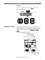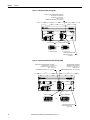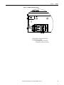
1
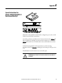
User Manual
Bulletin 1608N MiniDySC® Dynamic Sag Corrector
Single Phase Voltage Sag Correction 12...50 Amps
Important User Information
Read this document and the documents listed in the additional resources section about installation, configuration, and operation of this equipment
before you install, configure, operate, or maintain this product. Users are required to familiarize themselves with installation and wiring instructions in
addition to requirements of all applicable codes, laws, and standards.
Activities including installation, adjustments, putting into service, use, assembly, disassembly, and maintenance are required to be carried out by
suitably trained personnel in accordance with applicable code of practice.
If this equipment is used in a manner not specified by the manufacturer, the protection provided by the equipment may be impaired.
In no event will Rockwell Automation, Inc. be responsible or liable for indirect or consequential damages resulting from the use or application of this
equipment.
The examples and diagrams in this manual are included solely for illustrative purposes. Because of the many variables and requirements associated with
any particular installation, Rockwell Automation, Inc. cannot assume responsibility or liability for actual use based on the examples and diagrams.
No patent liability is assumed by Rockwell Automation, Inc. with respect to use of information, circuits, equipment, or software described in this
manual.
Reproduction of the contents of this manual, in whole or in part, without written permission of Rockwell Automation, Inc., is prohibited.
Throughout this manual, when necessary, we use notes to make you aware of safety considerations.
WARNING: Identifies information about practices or circumstances that can cause an explosion in a hazardous environment,
which may lead to personal injury or death, property damage, or economic loss.
ATTENTION: Identifies information about practices or circumstances that can lead to personal injury or death, property damage,
or economic loss. Attentions help you identify a hazard, avoid a hazard, and recognize the consequence.
IMPORTANT
Identifies information that is critical for successful application and understanding of the product.
Labels may also be on or inside the equipment to provide specific precautions.
SHOCK HAZARD: Labels may be on or inside the equipment, for example, a drive or motor, to alert people that dangerous
voltage may be present.
BURN HAZARD: Labels may be on or inside the equipment, for example, a drive or motor, to alert people that surfaces may
reach dangerous temperatures.
ARC FLASH HAZARD: Labels may be on or inside the equipment, for example, a motor control center, to alert people to
potential Arc Flash. Arc Flash will cause severe injury or death. Wear proper Personal Protective Equipment (PPE). Follow ALL
Regulatory requirements for safe work practices and for Personal Protective Equipment (PPE).
MiniDySC, Allen-Bradley, Rockwell Software, and Rockwell Automation are trademarks of Rockwell Automation, Inc. Trademarks not belonging to Rockwell Automation are property of their respective companies.
Additional Resources
These documents contain additional information concerning related products from Rockwell Automation.
Resource
Description
Industrial Automation Wiring and Grounding Guidelines, publication 1770-4.1
Provides general guidelines for installing a Rockwell Automation industrial system.
Product Certifications website, http://www.ab.com
Provides declarations of conformity, certificates, and other certification details.
You can view or download publications at http:/www.rockwellautomation.com/literature/. To order paper copies of
technical documentation, contact your local Allen-Bradley distributor or Rockwell Automation sales representative.
Table of Contents
Important User Information . . . . . . . . . . . . . . . . . . . . . . . . . . . . . . . . . . . . . . . . 2
Additional Resources . . . . . . . . . . . . . . . . . . . . . . . . . . . . . . . . . . . . . . . . . . . . . . . 2
Ch 1 - Installation
Installation Check List . . . . . . . . . . . . . . . . . . . . . . . . . . . . . . . . . . . . . . . . . . . . . 5
Inspecting and Unpacking . . . . . . . . . . . . . . . . . . . . . . . . . . . . . . . . . . . . . . . . . . 5
Location (Environment). . . . . . . . . . . . . . . . . . . . . . . . . . . . . . . . . . . . . . . . . . . . 6
Mounting Considerations . . . . . . . . . . . . . . . . . . . . . . . . . . . . . . . . . . . . . . . . . . 6
Rack Mount Considerations . . . . . . . . . . . . . . . . . . . . . . . . . . . . . . . . . . . . . . . . 6
Heat Dissipation . . . . . . . . . . . . . . . . . . . . . . . . . . . . . . . . . . . . . . . . . . . . . . . . . . . 6
Mounting Dimensions . . . . . . . . . . . . . . . . . . . . . . . . . . . . . . . . . . . . . . . . . . . . . 7
12 A -25 A SR/ER and 50 A SR MiniDySC . . . . . . . . . . . . . . . . . . . . . . 7
50 A ER MiniDySC . . . . . . . . . . . . . . . . . . . . . . . . . . . . . . . . . . . . . . . . . . . . 8
Wall Mounting the MiniDySC . . . . . . . . . . . . . . . . . . . . . . . . . . . . . . . . . . 8
Circuit Breaker Recommendations . . . . . . . . . . . . . . . . . . . . . . . . . . . . . . 9
Electrical Terminations . . . . . . . . . . . . . . . . . . . . . . . . . . . . . . . . . . . . . . . . . 9
Accessing Terminations. . . . . . . . . . . . . . . . . . . . . . . . . . . . . . . . . . . . . . . 10
L-N Versus L-L Configuration . . . . . . . . . . . . . . . . . . . . . . . . . . . . . . . . . . . . 10
Line to Neutral. . . . . . . . . . . . . . . . . . . . . . . . . . . . . . . . . . . . . . . . . . . . . . . 10
Line to Line. . . . . . . . . . . . . . . . . . . . . . . . . . . . . . . . . . . . . . . . . . . . . . . . . . 11
Completing Terminations . . . . . . . . . . . . . . . . . . . . . . . . . . . . . . . . . . . . . . . . 11
Ch 2- Operation
Applying Power. . . . . . . . . . . . . . . . . . . . . . . . . . . . . . . . . . . . . . . . . . . . . . . . . . 15
Alarm LED Flash Sequence . . . . . . . . . . . . . . . . . . . . . . . . . . . . . . . . . . . . . . . 15
Communications . . . . . . . . . . . . . . . . . . . . . . . . . . . . . . . . . . . . . . . . . . . . . . . . 16
Ch 3- Specifications and Dimensions
Specifications . . . . . . . . . . . . . . . . . . . . . . . . . . . . . . . . . . . . . . . . . . . . . . . . . . . . . 17
Approximate Dimensions. . . . . . . . . . . . . . . . . . . . . . . . . . . . . . . . . . . . . . . . . 18
Appendix A
Special Instructions for Rack-Mount MiniDySC . . . . . . . . . . . . . . . . . . . 21
Rockwell Automation Publication 1608N-UM002B-EN-P - May 2014
3
Table of Contents
Notes:
4
Rockwell Automation Publication 1608N-UM002B-EN-P - May 2014
Chapter
1
Installation
Installation Check List
Before proceeding, please take a few minutes to review the necessary steps to
install your MiniDySC.
• All packing materials and restraints have been removed.
• The MiniDySC is placed in its installed location.
• All conduits and cables are properly routed to the MiniDySC.
• All power cables are properly terminated.
• A ground conductor is properly installed.
• If neutral connection is required that it is properly terminated on the
MiniDySC.
• The area around the installed MiniDySC is clean and dust-free.
• Operational checks have been reviewed and completed.
ATTENTION: Metallic contamination inside the MiniDySC enclosure will void the
warranty
Inspecting and Unpacking
• Carefully inspect the outer packaging for evidence of damage during
transit. Do not install a damaged cabinet. Report any damage to the carrier
and contact your local sales or service immediately.
• Check the MiniDySC label for correct model number with the packaging
list to ensure you have received the correct voltage, current, and wiring
configurations.
• After removing the packaging material, inspect the contents for any
evidence of physical damage, and compare each item with the Bill of
Lading. If damage has occurred or shortages are evident contact your
carrier immediately.
Rockwell Automation Publication 1608N-UM002B-EN-P - May 2014
5
Chapter 1
Installation
Location (Environment)
NOTICE: Install this equipment in an indoor temperature-controlled area, free from
condensation and conductive contaminants such as carbon dust.
The MiniDySC must be installed in a protected environment. The location must
provide adequate airflow around the MiniDySC in an atmosphere free from
excessive dust, corrosive fumes, or conductive contaminants. Do not operate the
MiniDySC in an environment where the ambient temperature or humidity is
beyond the specified limits given in this manual.
Mounting Considerations
The MiniDySC can be wall mounted. It can also be mounted inside an enclosure
as long as the ambient temperature remains at or below 40°C.
Note: The input and output wiring is from the bottom of the MiniDySC and considerations
should be made to accommodate the additional space. The weights for the MiniDySC are given
on page 18.
Rack Mount Considerations
Special instructions for installing the rack-mount MiniDySC are in Appendix A.
Heat Dissipation
The table below provides full-load power dissipation for the three MiniDySC
sizes. Refer to this chart when calculating heat dissipation for placing the
MiniDySC in your cabinet.
Table 1 - Power Dissipation
MiniDySC rating
(A)
12
25
50
6
Heat Loss
(W)
SR/ER
Heat Loss
(Btu/h)
Efficiency
(%)
SR
30
103
98
SR
47
161
98.5
ER
70
240
98.0
SR
94
321
98.5
ER
140
479
98.0
Rockwell Automation Publication 1608N-UM002B-EN-P - May 2014
Installation
Mounting Dimensions
Chapter 1
12 A -25 A SR/ER and 50 A SR MiniDySC
Figure 1 - Top Keyed MiniDySC
A
B
Lower Mounting Holes Located
Under Wiring Access Cover
Vent holes in both sides.
Maintain 3 in. clearance
for proper cooling.
C
Figure 1 shows the top keyed and bottom hole dimensions for the 12 A, 25 A
(Standard and Extended ride through SR/ER) and 50 A SR MiniDySC. To
access the lower mounting holes, four cover screws (two on each side of lower
cover) must be removed.
ATTENTION: DO NOT REMOVE THE TOP COVER. WARRANTY WILL BE VOIDED IF IT
IS REMOVED.
Table 2 - 12/25/50 Amp SR/ER Mounting Dimensions
A
Rating
12 A
25 A SR
25 A ER
50 A SR
B
in.
[mm]
C
7.0
[177.8]
17.95
[455.9]
7.0
[177.8]
12.0
[304.8]
17.95
[455.9]
13.75
[349.3]
Rockwell Automation Publication 1608N-UM002B-EN-P - May 2014
7
Chapter 1
Installation
50 A ER MiniDySC
Figure 2 provides mounting dimensions for the 50 A extended ride through (ER).
Key slot dimensions are provided in Figure 14.
Figure 2 - 50 A ER Mounting Dimensions
16.00
(406.40)
Vent holes in both sides.
Maintain 3 in. clearance
for proper cooling.
17.52
(444.93)
Wall Mounting the MiniDySC
There are two methods of mounting the MiniDySC to wall board as show in
Figure 3
Figure 3 - Wall Mounting
• Option 1: Mount the MiniDySC to ½ inch wallboard using (4) #6 hollow
wall fasteners or (4) #10 toggle bolts.
• Option 2: Center one side of the MiniDySC on the wall stud and fasten
to a wood stud with (2) 2 – inch long #8 Phillips bugle-head screws or to a
metal stud with (2) 2-inch long #8 Philip bugle-head self drilling screws.
Fasten the other side of the MiniDySC with (2) hollow wall fasteners or
(2) #10 toggle bolts.
8
Rockwell Automation Publication 1608N-UM002B-EN-P - May 2014
Installation
Chapter 1
Circuit Breaker Recommendations
Branch circuit protection upstream of the MiniDySC is required
Table 3 - Circuit Breaker Recommendations
Rated MiniDySC (Amps)
Maximum Rated Breaker (Amps)
12
15
25
35
50
70
Electrical Terminations
A qualified electrician must install the MiniDySC. To access the connections,
remove the four screws on the bottom cover and lift off the cover. The MiniDySC
is furnished with one of the terminal block configurations as shown in the figures
below.
Figure 4 - Power Terminal Locations
ACCESS COVER
Rockwell Automation Publication 1608N-UM002B-EN-P - May 2014
9
Chapter 1
Installation
Accessing Terminations
Three knockout holes are provided for conduit entry, as shown in Figure 5. Take
care to avoid dropping any metal filings inside the enclosure. Metallic
contamination will void the product warranty. See Figure 8, Figure 9, and
Figure 10 for input/output terminal locations.
Figure 5 - Knockout Hole Locations
COMMUNICATIONS
.89 [22.6mm] DIAMETER EKO
IMPORTANT
L-N Versus L-L Configuration
2X INPUT AND OUTPUT
AC CONNECTIONS.
.89 [22.6mm] DIAMETER EKO
Metallic Particles inside the enclosure will void the warranty
MiniDySC terminals are labeled in accordance with the AC input source type.
Bulletin 1608N part numbers containing V2 are configured for single-phase
line-to-neutral (phase-to-neutral) input, with input terminals labeled L1 and N. Part
numbers containing V1 are configured for line-to-line (phase-to-phase) input, with
input terminals labeled L1 and L2. Select the correct connection diagram between
Figure 6 (L-N) and Figure 7 (L-L).
Line to Neutral
MiniDySC L-N models must be connected as in Figure 6 to operate properly.
Figure 6 - Line to Neutral Configuration
L1 N
L-N
INPUT SOURCE
N X1
User Supplied
Circuit Breaker
OUTPUT TO LOADS
L1
X1
N
N
GND
GND
GROUND
STUD
Terminal Block Configurations
L1 N
N X1
12A-25A SR
10
GR
L1
X1
N
N
N
N
X1
L1
GR
GR
25A ER
50A SR/ER
Rockwell Automation Publication 1608N-UM002B-EN-P - May 2014
Installation
Chapter 1
Line to Line
MiniDySC L-L models must be connected as in Figure 7 to operate properly.
Figure 7 - Line to Line Configuration
L1 L2 X2 X1
L-L
User Supplied
Circuit Breaker
INPUT SOURCE
OUTPUT TO LOADS
L1
X1
L2
X2
GND
GND
GROUND
STUD
Terminal Block Configurations
L1 L2 X1 X2
GR
12A-25A SR
Completing Terminations
L1
X1
L2
X2
X1
L2
X2
L1
GR
GR
25A ER
50A SR/ER
Output terminals are marked X1 and N or X1 and X2. If multiple loads are
served by the MiniDySC a separate distribution box must be provided. Only one
conductor should be terminated in each MiniDySC terminal block position.
Terminal torque requirements are shown in Figure 8, Figure 9, Figure 10, and
Figure 11.
Figure 8 - 12 and 25 Amp Standard Ride-through (SR)
INPUT/OUTPUT TERMINAL RATING:
22-8 AWG (0.5-6mm2)
TORQUE: 7.1-8.9 lb-in.
(0.8-1.0 N-m)
WIRE STRIP LENGTH: .47" [12mm]
FUSE
TERMINAL BLOCK
LINE TO LINE
LINE TO NEUTRAL
OR
L1-L2-X1-X2-GR
Rockwell Automation Publication 1608N-UM002B-EN-P - May 2014
L1-N-N-X1-GR
#10-32 GROUND STUD
TORQUE: 29 in-lb.
(3.3 N-m)
11
Chapter 1
Installation
Figure 9 - 25 Amp Extended Ride Through (ER)
INPUT/OUTPUT TERMINAL RATING:
22-8 AWG (0.5-6mm2)
TORQUE: 7.1-8.9 lb-in.
(0.8-1.0 N-m)
WIRE STRIP LENGTH: .47" [12mm]
FUSE
TERMINAL BLOCK
LINE TO LINE
LINE TO NEUTRAL
OR
L1-L2-X1-X2-GR
L1-N-N-X1-GR
1/4-20 GROUND STUD
TORQUE: 65 in-lb.
(7.3 N-m)
Figure 10 - 50 Amp Standard/Extended Ride-through (SR/ER)
INPUT/OUTPUT TERMINAL RATING:
16-0 AWG (1.5 - 50 mm2)
TORQUE: 24.3-26.1 lb-in.
(2.7 - 2.9 N-m)
WIRE STRIP LENGTH: .67" [17mm]
FUSE
GR TERMINAL RATING:
22-8AWG (0.5-6mm2)
TORQUE: 7.1-8.9 lb.-in.
(0.8-1 N-m)
WIRE STRIP LENGTH: .47" [12mm]
TERMINAL BLOCK
LINE TO LINE
LINE TO NEUTRAL
OR
X1-X2-L2-L1-GR
X1-N-N-L1-GR
1/4-20 GROUND STUD
TORQUE: 65 in-lb.
(7.3 N-m)
12
Rockwell Automation Publication 1608N-UM002B-EN-P - May 2014
Installation
Chapter 1
Figure 11 - Communications (Dry Contacts)
CUSTOMER COMMUNICATIONS
CONNECTION AREA.
24-12 AWG (0.2-2.5mm2)
TORQUE: 5.0 lb-in (0.6 N-m)
Rockwell Automation Publication 1608N-UM002B-EN-P - May 2014
13
Chapter 1
Installation
Notes:
14
Rockwell Automation Publication 1608N-UM002B-EN-P - May 2014
Chapter
2
Operation
The MiniDySC is fully automatic and requires no user intervention for normal
operation.
1. Before applying power to the MiniDySC, ensure that all input/output
wiring including grounding has been completed and that the wiring access
cover is on and screwed down.
Applying Power
2. The load should be connected prior to performing system checks.
3. Apply power, note that the green “Normal” LED will be illuminated.
4. Verify that the output (load) voltage is present and within nominal rating.
5. During normal operation the green LED will remain on.
NOTICE: Cycling input power in the sequence OFF--ON--OFF--ON within a one minute period will
cause a "Inverter Limit Cycle Timeout" alarm. In such case, the red LED will blink and sag
correction will be inhibited for one minute (the condition will automatically reset after one
minute).
Alarm LED Flash Sequence
The MiniDySC continuously monitors its condition to help ensure reliable
operation. Status is provided by two front panel indicators, a green Normal LED
and a red Alarm LED. The green Normal LED will be lighted under normal
operating conditions. Events that may affect the ability of the MiniDySC to
protect the load will activate the Alarm LED. Conditions that the user can
correct, such as an overload condition, will be indicated by an encoded series of
red LED flashes. The flash code is repeated after a two second pause for as long as
the condition persists. User correctable Alarm conditions are listed in Table 4.
For any other Alarm code, or a constant series of rapid flashing, consult
Rockwell Automation Technical Support.
Table 4 - Alarm LED Flash Descriptions
Alarm Name
Inverter Run Time
out
Inverter Limit Cycle
Timeout
Number of
Flashes
Alarm Description
Alarm Resolution
DySC inverter had a total cumulative runtime of more than rated.
No action is needed
Power was re-applied more than once within a 58 second period.
No action is needed
Inverter inhibited because load current exceeded maximum rating.
Reduce the load
Static switch heatsink temperature was greater than maximum rating.
• Verify ambient temperature is within specification
• Check for damaged fans
• Check for dirty or obstructed air vents.
Positive or negative half of DC bus voltage exceeded maximum rating.
• Verify line voltage is within ratings.
• Verify proper DySC application
• Call Service
3
Overload
Static Switch Over Temperature
4
DC Bus
Over-Voltage
5
Rockwell Automation Publication 1608N-UM002B-EN-P - May 2014
15
Chapter 2
Operation
Communications
16
Two relay contacts indicate MiniDySC status. The contacts are form A and close
upon occurrence of the named event: (a) OUTPUT OK, when output voltage
remains between 87…110% of nominal value; and (b) a system ALARM event.
The relay contact ratings are 24V DC at 1 A. The communications wiring area
detail is shown in Figure 11. A barrier plate prevents contact between
communications wiring and power wiring.
Rockwell Automation Publication 1608N-UM002B-EN-P - May 2014
Chapter
3
Specifications and Dimensions
Table 5 - Technical Specifications – MiniDySC (12…50 Amps)
Electrical Input/Output (Normal Mode—Static Switch)
Connection Configuration
Series-connected with load. Under normal line condition, the static switch passes utility voltage directly to the load
Standard Input Voltage DySC
1Phase: 120, 208, 220, 230, 240V
Voltage Range
± 10%
Output Current (Static Switch)
0...100% of rated rms current, continuous
Current Overload (Static Switch) for 12A, 50A models 200% @ 30 Sec., 400% @ 5 Sec., 600% @ 0.5 Sec.
Current Overload (Static Switch) for 25A models
200% @ 30 Sec., 280% @ 5 Sec., 450% @ 0.5 Sec.
Frequency
50/60 Hz Auto Sensing
Frequency Range (tracking)
45 to 65 Hz
Surge Protection Device (SPD)
Built-in 3-Layers consisting of MOVs & Capacitors
Efficiency
> 98%
Phase (wiring)
1 phase (L-L & L-N)
Sag Detection Voltage
88.5% of rated voltage
Response Time (typical)
0.7 ms detection, 1.2 ms inverter reaction (<2ms)
Electrical Output (Sag Correction Mode—Inverter)
Output Voltage
Matches pre-sag input voltage
Voltage Regulation
+/- 5% typical, +5% / -13% of nominal max
Output Current
Rated RMS (12, 25, or 50 A)
Crest Factor (at rated load)
1.45
Load
Power factor range -0.5 to +0.9
DC component <2% of rated current
Voltage Waveform (typical)
Sine wave
Voltage Sag Correction Times
Single Event
87% to 50% voltage remaining
5 seconds SR & ER
Sags to zero voltage remaining
50ms or 200ms (SR or ER). Based on load at nameplate ratings with a power factor of 0.7
Multiple Events
Max Sag Correction Time
5 seconds cumulative usage
Seqential Sag Recovery
0 seconds (assuming cumulative run-time available)
Full Recovery Time
Max 5 minutes to full recovery
Mechanical
Enclosure Ratings
NEMA 1 (IP20)
Cable Entry
Bottom
Cooling
Forced Air
Access
Lower front for servicing and connections
Accessibility (Wiring)
DIN compression terminal block
Communications / User Interface
Indicators
Normal and Alarm LEDs
Connectivity
OUTPUT OK and ALARM contacts, Form A, 24VDC at 1A
Environmental
Ambient Temperature
0 ...+40°C
Storage Temperature
-40°C ...+75°C
Relative Humidity
0 to 95% non-condensing
Altitude
Rated current available to 1000m (3300ft). De-rate output current 10% per 1000m, from 1000m to 3000m (9900ft).
Heat Dissipation (max)
12A – 100 BTU/Hr
25A – 160 BTU/Hr
50A – 320 BTU/Hr.
Audible Noise
< 50dBA at 1 meter
Certifications
Agency Approvals
cULus 1012 Listed, Exceeds SEMI F47 Standard
Rockwell Automation Publication 1608N-UM002B-EN-P - May 2014
17
Chapter 3
Specifications and Dimensions
Approximate Dimensions
Dimensions
HxWxD
in. [mm]
Standard Run-time (SR)
22 x 10 x 4 [550.8 x 254 x 101.6]
21 x 19 x 4 [533.4 x 482.6 x 101.6]
Extended Run-time (ER)
21 x 19 x 4 [533.4 x 482.6 x 101.6]
21 x 19 x 7 [533.4 x 482.6 x 177.8]
Rating
(A)
12, 25
50
25
50
Weight
lbs.[kg]
18.6 [8.44]
34.5 [15.5]
32.5 [14.7]
51.5 [23.4]
Dimensions in inches [mm]. Dimensions are not intended to be used for manufacturing purposes.
Figure 12 - 12 Amp and 25 Amp SR Dimensions
.28
7.19
9.27
235.36
R.26
6.50
.350
8.89
A
7.00
177.80
UPPER
MOUNTING
3.56
90.51
DETAIL A
MOUNTING
KEYHOLE
2 PLACES
21.14
536.97
17.95
455.93
VERTICAL
MOUNTING
B
7.00
177.80
LOWER
MOUNTING
LOWER MOUNTING
HOLES LOCATED UNDER
ACCESS COVER. SEE DETAIL B
COMMUNICATIONS
.89 [22.6mm] DIAMETER EKO
2X INPUT AND OUTPUT
AC CONNECTIONS.
.89 [22.6mm] DIAMETER EKO
3.18
80.85
DETAIL B
1.43
36.40
5.18
131.65
LOWER MOUNTING HOLE
LOCATION: 2X .281 DIA. HOLES
UNDER ACCESS COVER.
18
Rockwell Automation Publication 1608N-UM002B-EN-P - May 2014
1.31
33.35
Specifications and Dimensions
Chapter 3
Figure 13 - 25 Amp ER /50 Amp SR Dimensions
R.14
3.59
16.02
406.83
.51
13
.350
8.89
A
12.00
304.80
UPPER
MOUNTING
3.56
90.51
DETAIL A
MOUNTING
KEYHOLE
2 PLACES
21.14
536.97
17.95
455.93
VERTICAL
MOUNTING
13.75
349.25
LOWER
MOUNTING
LOWER MOUNTING
HOLES LOCATED UNDER
ACCESS COVER. SEE DETAIL B
B
2X INPUT AND OUTPUT
AC CONNECTIONS.
.89 [22.6mm] DIAMETER EKO
COMMUNICATIONS
.89 [22.6mm] DIAMETER EKO
1.31
33.27
3.08
78.32
11.93
303.11
DETAIL B
4.83
122.77
LOWER MOUNTING HOLE
LOCATION: 2X .281 DIA. HOLES
UNDER ACCESS COVER.
Rockwell Automation Publication 1608N-UM002B-EN-P - May 2014
19
Chapter 3
Specifications and Dimensions
Figure 14 - 50 Amp ER Dimensions
.28
7.21
.51
13
.350
8.89
DETAIL A
MOUNTING
KEYHOLE
2 PLACES
19.02
483.03
OVERALL
7.06
179.44
17.52
444.93
MOUNTING
A
20.27
514.74
16.00
406.40
MOUNTING
2X .281
MOUNTING
HOLES
COMMUNICATIONS
.89 [22.6mm] DIAMETER EKO
2X INPUT AND OUTPUT
AC CONNECTIONS.
.89 [22.6mm] DIAMETER EKO
4.81
122.28
11.93
303.11
20
Rockwell Automation Publication 1608N-UM002B-EN-P - May 2014
3.08
78.32
4.83
122.77
Appendix
A
Special Instructions for
Model 1608N-012A120V2S-R
Rack-Mount MiniDySC
MiniDySC model 1608N-012A120V2S-R is configured to protect line-corded
loads in a 19-inch IT rack environment.
Amended specifications and dimensions for this model are listed in Table 6. All
other specifications, including environmental and certifications, are as listed in
Table 5. This model does not include alarm contacts. LED indicators are frontfacing.
Included mounting hardware will accommodate any of the mounting
orientations shown in Figure 15, including 4-post mounting in racks up to 26 in.
deep.
This MiniDySC model contains no user-serviceable parts.
ATTENTION: DO NOT REMOVE THE TOP COVER. WARRANTY WILL BE VOIDED IF IT
IS REMOVED.
Rockwell Automation Publication 1608N-UM002A-EN-P - May 2014
21
Appendix A
Table 6 - Technical Specifications - Rack-Mount MiniDySC, PN 1608N-012A120V2S-R
Electrical
Input Voltage (nominal)
1 Phase (L-N), 120V ±10%
Output Current
12 A
Upstream Circuit Breaker (required) Rating
15 A
Mechanical
Mounting Hardware Kit (included)
Weight
(2) Mounting Brackets (see Figure 16)
(8) Cage Nut, 10-32
(16) Screw, 3/8 in. Phillips, 10-32, with lock washer
(8) Screw, 3/4 in. slotted Truss, 10-32
22.5 lb
Line Cord Length
6 ft (minimum)
Line Plug
NEMA 5-15P
Load Receptacles
Six (6) NEMA 5-15R
Cooling
Forced air: rear intake, side exhaust
Dimensions
Height
2U (3.459 in.)
Width
19 in. (front panel)
Depth
18.9 in., excluding line cord bend radius
Figure 15 - Rack Mounting Options for model 1608N-012A120V2S-R
Front Mount
Mid-Mount
Figure 16 - Mounting Bracket
22
Rockwell Automation Publication 1608N-UM002A-EN-P - May 2014
4-Post Mount
Rockwell Automation Support
Rockwell Automation provides technical information on the Web to assist you in using its products.
At http://www.rockwellautomation.com/support, you can find technical manuals, technical and application notes, sample
code and links to software service packs, and a MySupport feature that you can customize to make the best use of these
tools. You can also visit our Knowledgebase at http://www.rockwellautomation.com/knowledgebase for FAQs, technical
information, support chat and forums, software updates, and to sign up for product notification updates.
For an additional level of technical phone support for installation, configuration, and troubleshooting, we offer
TechConnectSM support programs. For more information, contact your local distributor or Rockwell Automation
representative, or visit http://www.rockwellautomation.com/support/.
Installation Assistance
If you experience a problem within the first 24 hours of installation, review the information that is contained in this
manual. You can contact Customer Support for initial help in getting your product up and running.
United States or Canada
1.440.646.3434
Outside United States or Canada
Use the Worldwide Locator at http://www.rockwellautomation.com/rockwellautomation/support/overview.page, or contact your local
Rockwell Automation representative.
New Product Satisfaction Return
Rockwell Automation tests all of its products to help ensure that they are fully operational when shipped from the
manufacturing facility. However, if your product is not functioning and needs to be returned, follow these procedures.
United States
Contact your distributor. You must provide a Customer Support case number (call the phone number above to obtain one) to your
distributor to complete the return process.
Outside United States
Please contact your local Rockwell Automation representative for the return procedure.
Documentation Feedback
Your comments will help us serve your documentation needs better. If you have any suggestions on how to improve this
document, complete this form, publication RA-DU002, available at http://www.rockwellautomation.com/literature/.
Publication 1608N-UM002B-EN-P - May 2014
DIR 10000723485
Copyright © 2014 Rockwell Automation, Inc. All rights reserved. Printed in the U.S.A