1
MicroLogix 1400
Embedded Web
Server
Bulletin 1766 Controllers
User Manual
Important User Information
Solid state equipment has operational characteristics differing from those of
electromechanical equipment. Safety Guidelines for the Application,
Installation and Maintenance of Solid State Controls (publication SGI-1.1
available from your local Rockwell Automation sales office or online at
http://literature.rockwellautomation.com) describes some important
differences between solid state equipment and hard-wired electromechanical
devices. Because of this difference, and also because of the wide variety of
uses for solid state equipment, all persons responsible for applying this
equipment must satisfy themselves that each intended application of this
equipment is acceptable.
In no event will Rockwell Automation, Inc. be responsible or liable for
indirect or consequential damages resulting from the use or application of
this equipment.
The examples and diagrams in this manual are included solely for illustrative
purposes. Because of the many variables and requirements associated with
any particular installation, Rockwell Automation, Inc. cannot assume
responsibility or liability for actual use based on the examples and diagrams.
No patent liability is assumed by Rockwell Automation, Inc. with respect to
use of information, circuits, equipment, or software described in this manual.
Reproduction of the contents of this manual, in whole or in part, without
written permission of Rockwell Automation, Inc., is prohibited.
Throughout this manual, when necessary, we use notes to make you aware
of safety considerations.
WARNING
IMPORTANT
ATTENTION
Identifies information about practices or circumstances that can cause
an explosion in a hazardous environment, which may lead to personal
injury or death, property damage, or economic loss.
Identifies information that is critical for successful application and
understanding of the product.
Identifies information about practices or circumstances that can lead
to: personal injury or death, property damage, or economic loss.
Attentions help you identify a hazard, avoid a hazard, and recognize
the consequence
SHOCK HAZARD
Labels may be on or inside the equipment, such as a drive or motor, to
alert people that dangerous voltage may be present.
BURN HAZARD
Labels may be on or inside the equipment, such as a drive or motor, to
alert people that surfaces may reach dangerous temperatures.
Rockwell Automation, Allen-Bradley, SLC 5/02, SLC 5/03, PLC-5, MicroLogix, SLC 500, RSLogix, RSLinx, RSLogix 500, RSLogix
Micro and TechConnect are trademarks of Rockwell Automation, Inc.
Trademarks not belonging to Rockwell Automation are property of their respective companies.
Table of Contents
Chapter 1
MicroLogix 1400 Embedded Web
Server
How to Use This Chapter . . . . . . . . . . . . . . . . . . . . . . . . . . . . . . . . . . . . 3
Typical Applications. . . . . . . . . . . . . . . . . . . . . . . . . . . . . . . . . . . . . . . . . 3
Browser Requirements . . . . . . . . . . . . . . . . . . . . . . . . . . . . . . . . . . . . . . . 3
Connect the MicroLogix 1400 controller to the Network . . . . . . . . . . . 4
Navigate the MicroLogix 1400 Controller . . . . . . . . . . . . . . . . . . . . . . . 6
Chapter 2
Use Data Views to Access
Controller Data
How to Use This Chapter . . . . . . . . . . . . . . . . . . . . . . . . . . . . . . . . . . . . 7
Overview of Data Views . . . . . . . . . . . . . . . . . . . . . . . . . . . . . . . . . . . . . 7
Change an Access Group. . . . . . . . . . . . . . . . . . . . . . . . . . . . . . . . . . . . . 8
Data View Page . . . . . . . . . . . . . . . . . . . . . . . . . . . . . . . . . . . . . . . . . 9
Change Data Table Files . . . . . . . . . . . . . . . . . . . . . . . . . . . . . . . . . . . . 10
How to Change a Data File Type . . . . . . . . . . . . . . . . . . . . . . . . . . 10
Disable Web View . . . . . . . . . . . . . . . . . . . . . . . . . . . . . . . . . . . . . . . . . 12
Chapter 3
Monitor Diagnostics
How to Use This Chapter . . . . . . . . . . . . . . . . . . . . . . . . . . . . . . . . . . . 15
MicroLogix 1400 Controller Diagnostics . . . . . . . . . . . . . . . . . . . . . . . 15
Network Status . . . . . . . . . . . . . . . . . . . . . . . . . . . . . . . . . . . . . . . . . . . . 18
Chapter 4
Administrative Settings
Server Settings . . . . . . . . . . . . . . . . . . . . . . . . . . . . . . . . . . . . . . . . . . . . 21
Customize Server Settings . . . . . . . . . . . . . . . . . . . . . . . . . . . . . . . . 21
Chapter 5
User Management
How to Use This Chapter . . . . . . . . . . . . . . . . . . . . . . . . . . . . . . . . . . . 23
User Accounts and Privilege Classes. . . . . . . . . . . . . . . . . . . . . . . . . . . 24
Configure Access Limits for Web Pages. . . . . . . . . . . . . . . . . . . . . . . . 24
Recover with Unknown Password . . . . . . . . . . . . . . . . . . . . . . . . . . . . 26
Chapter 6
Simple Web Pages
Device Information . . . . . . . . . . . . . . . . . . . . . . . . . . . . . . . . . . . . . 28
Ethernet Configuration . . . . . . . . . . . . . . . . . . . . . . . . . . . . . . . . . . 28
Diagnostic Information . . . . . . . . . . . . . . . . . . . . . . . . . . . . . . . . . . 29
Data Table Memory Map . . . . . . . . . . . . . . . . . . . . . . . . . . . . . . . . 31
Chapter 7
User Provided Pages
HTML Pages . . . . . . . . . . . . . . . . . . . . . . . . . . . . . . . . . . . . . . . . . . . . . 33
Generating Custom Data Table Monitor Pages . . . . . . . . . . . . . . . . . . 35
Index
1
Publication 1766-UM002B-EN-P - September 2015
2
Table of Contents
Notes:
Publication 1766-UM002B-EN-P - September 2015
Chapter
1
MicroLogix 1400 Embedded Web Server
How to Use This Chapter
Rockwell Automation offers enhanced MicroLogix 1400 controllers for your
EtherNet/IP control systems so you can monitor data remotely via web pages.
This chapter shows how you can use a MicroLogix 1400 controller in your
control system.
Topic
Typical Applications
Page
Typical Applications
3
Browser Requirements
3
Connect the MicroLogix 1400 controller to the Network
4
Navigate the MicroLogix 1400 Controller
6
With the MicroLogix 1400 controller, you can access controller and control
system data with different and remote access applications. With a web browser,
you can easily monitor live MicroLogix 1400 controller data remotely.
With the MicroLogix 1400 controller, you can access Simple web page view,
and custom-designed User Provided page views. Simple web pages use only
HTML tags and are useful in limited-communication environments where
radio modems are used.
Browser Requirements
You can access the MicroLogix 1400 controllers only with Internet Explorer
6.0, Opera 9.23 , FireFox 2.0.0.14, or Safari 3.0.4, or higher . To access data
view pages, the browser requires Javascript and XML support.
The supported display sizes start from 640 x 480. Smaller display sizes also
work but require scrolling to view the information.
3
Publication 1766-UM002B-EN-P - September 2015
4
MicroLogix 1400 Embedded Web Server
Connect the MicroLogix
1400 controller to the
Network
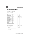
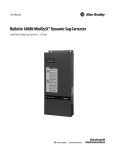
1. Connect the module to
the network.
Connect the MicroLogix 1400 controller to the Ethernet network. The RJ-45
connector is on the left-hand side of the module.
44592
2. Obtain an IP address.
For more information, see
MicroLogix1400 Programmable
Controllers User Manual
1766-UM001.
By default, the MicroLogix 1400 controller is BOOTP enabled. If you connect
the MicroLogix 1400 controller to a network that has a BOOTP server, that
server will assign an IP address to the MicroLogix 1400 controller and the
LCD screen of the MicroLogix 1400 controller will display BOOTP IP
address.
If your network does not have a BOOTP server, use one of the methods
described in the MicroLogix 1400 Programmable Controllers User Manual
1766-UM001 to assign an IP address to the MicroLogix 1400 controller.
Publication 1766-UM002B-EN-P - September 2015
MicroLogix 1400 Embedded Web Server
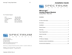
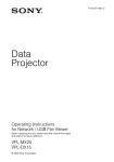
3. Access the Home page of
the web server.
5
In your web browser’s Address box, enter the IP address of the MicroLogix
1400 controller. The Home page is displayed.
Specify the IP address of the
MicroLogix 1400 controller in the
Address window of your web
browser.
This is the controller’s Home page.
4. Log into the web server.
Many of the features of the MicroLogix 1400 controller require you to log in
with appropriate access. If you select a feature, such as Data Views, the
MicroLogix 1400 controller prompts you to enter your user name and
password. The user name is either administrator or guest. The password is
ml1400 for administrator and guest for guest.
Default Access
User Name: administrator or guest
(case sensitive)
Password:
(ml1400 for administrator, guest for guest)
You can set up as many as 10 user accounts. Each account can have read, write,
or administrator access. For more information, see User Management .
Publication 1766-UM002B-EN-P - September 2015
6
MicroLogix 1400 Embedded Web Server
Security Warning Page
For MicroLogix 1400 FRN 15.3 or later only. To enhance web server security,
upon logging in to the MicroLogix 1400 Web Server page with the default
administrator account and default password, a warning displays to notify the
user to change the default password.
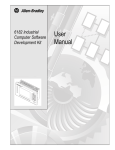
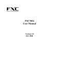
Navigate the MicroLogix
1400 Controller
Tabs across the top match the documents
within a folder, as shown in the left
navigation panel.
Click folders to open and close
additional levels of information.
Click a document to display a
web page showing specific
information.
Publication 1766-UM002B-EN-P - September 2015
You navigate the web server’s web pages by using the navigation panel on the
left of the screen. There are also tabs across the top you can click to navigate
the folders containing documents.
Chapter
2
Use Data Views to Access Controller Data
How to Use This Chapter
The MicroLogix 1400 controller provides access to the controller data table
files. This chapter shows you how to set up views of data table files.
Topic
Overview of Data Views
Page
Overview of Data Views
7
Change an Access Group
8
Monitor Data Views and Data Table File
9
Change Data Table Files
10
Disable Web View
12
Data views give you the ability to read controller data via a browser interface.
The MicroLogix 1400 controller provides web pages that let you configure a
set of files (a data view) that can be read.
A data view consists of an HTML file and an XML file with data file
information. The HTML file is in a readable ASCII format. It contains the File
Name, File Type, # of Element, and Access Group.
7
Publication 1766-UM002B-EN-P - September 2015
8
Use Data Views to Access Controller Data
Change an Access Group
Each data view contains a group of files that you want to monitor. Each
MicroLogix 1400 controller can support multiple data views. One browser
supports only one data view, so if you want to look at many data views, you
need to run a corresponding number of browsers.
You change an access group from the Data Views → New Data View page.
1. From the Access Group pull-down menu of the given data table file,
choose one of the following access group types:
• Administrator (all access)
• Write (read/write access only)
• Read (read access only)
2. Choose Administrator, Write, or Read from the Access Group
pull-down menu to change a file's access group.
3. Click Apply
specified.
Publication 1766-UM002B-EN-P - September 2015
to change an access group for the data table file you
Use Data Views to Access Controller Data
Monitor Data Views and
Data Table File
9
Use the Data Views → Data Views page to view existing data table files.
Click the file name to view the data within a data table file.
Data View Page
The Data Views page displays a list of the data table files, their type, and size in
elements for a connected MicroLogix 1400, as shown in the following
example.
Each file contains a hyperlink that takes you to the specific Data Views page
for that file. When you click a particular file, the Data Views page appears,
displaying the contents of the data table file you selected.
Publication 1766-UM002B-EN-P - September 2015
10
Use Data Views to Access Controller Data
The available and default display formats depend on the data type of the file.
Click Back to display the previous page. To refresh the data view, click Update.
Change Data Table Files
The data in the Data File Types such as Binary, Integer, Long, Float, and String
can be changed. The Binary, Integer, and Long types support all the Display
formats. You can edit Binary types by bit, and the Octal, Decimal, and
Hexadecimal types by element. A user account with either Write or
Administrator access level can change the Data Table Files. When you click N7
in Data Views, Data Writable appears beside a Data File Type (Integer here) as
shown below.
How to Change a Data File Type
In the steps that follow, a Binary type is assumed.
Publication 1766-UM002B-EN-P - September 2015
Use Data Views to Access Controller Data
11
1. Change Display As to Binary, then the following screen appears.
2. Double-click the data you want to change, then the background color
turns pink.
3. Enter a value and either press Enter or click an area in the screen, then a
confirmation window appears.
Publication 1766-UM002B-EN-P - September 2015
12
Use Data Views to Access Controller Data
4. Click OK to change the value.
The following screen appears when the value is successfully saved into
the server.
If the following screen appears, the value is not saved and the value
returns to the original value.
If you want to change the data in Decimal, click the pull-down menu to change
the Display As to Decimal and follow the steps described. The steps also apply
to the String type.
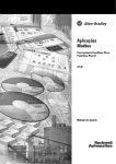
Disable Web View
Publication 1766-UM002B-EN-P - September 2015
Using RSLogix 500/RSLogix Micro V8.10 or higher, you can disable
individual data files from being viewed via any web browser by selecting the
data file’s properties page and checking the Web View Disable checkbox as
shown below. Any data file property changes must be made offline and
downloaded to the processor or later.
Use Data Views to Access Controller Data
13
Publication 1766-UM002B-EN-P - September 2015
14
Use Data Views to Access Controller Data
Notes:
Publication 1766-UM002B-EN-P - September 2015
Chapter
3
Monitor Diagnostics
How to Use This Chapter
This chapter describes the diagnostics presented on the user-oriented
diagnostic pages.
Topic
MicroLogix 1400 Controller
Diagnostics
Page
MicroLogix 1400 Controller Diagnostics
15
Diagnostic Overview
16
Network Settings
17
Network Status
18
The MicroLogix 1400 controller provides four diagnostic pages of
user-oriented diagnostics.
Topic
Web page
Overview of the current configuration of the Diagnostics → Diagnostic Overview
MicroLogix 1400 controller
15
Summary of the network settings
configured for the MicroLogix 1400
controller
Diagnostics → Network Settings
Ethernet statistics
Diagnostics → Network Status
Publication 1766-UM002B-EN-P - September 2015
16
Monitor Diagnostics
Diagnostic Overview
The Diagnostics → Diagnostic Overview page presents a summary of the
current configuration and overall status of the MicroLogix 1400 controller.
This summary includes:
• Ethernet link.
• Ethernet Connections.
This field
Specifies
Ethernet Link
Port Speed
whether the Ethernet port is operating at 10 Mbps or 100 Mbps
Port Duplex
whether the Ethernet port is operating at half duplex or full duplex
Auto negotiate Status
whether the port speed and duplex mode were determined via autonegotiation or whether
they were manually configured
Ethernet Connections
Current Ethernet Connections
current number of active connections
Incoming Ethernet Connections
current number of incoming connections
Outgoing Ethernet Connections
current number of outgoing ethernet connections
Ethernet Connection Limit
maximum number of Ethernet incoming/outgoing connections
Publication 1766-UM002B-EN-P - September 2015
Monitor Diagnostics
Network Settings
17
The Diagnostics → Network Settings page presents a summary of the current
Ethernet configuration for MicroLogix 1400. This summary includes:
• Ethernet address details.
Any fields not configured remain blank.
This field
Specifies
Network Interface
Ethernet Address (MAC)
Ethernet (MAC) address of the controller
IP Address
IP address for the controller
Subnet Mask
subnet mask for the controller
Default Gateway
gateway address for the controller
Primary Server Name
DNS server names, if using DNS addressing
Secondary Server Name
Domain Name
domain name for the web server module, if using DNS addressing
Publication 1766-UM002B-EN-P - September 2015
18
Monitor Diagnostics
Network Status
The Diagnostics → Network Status page presents a summary of the status of
communication activity on the Ethernet network. This summary includes:
• Ethernet network configuration.
• packets sent and received over the Ethernet network.
• frames sent and received over the Ethernet network.
This field
Specifies
Interface Counters
Rx Octets
Octets received on the Ethernet interface
Tx Octets
Octets sent on the Ethernet interface
Rx Packets
Packets received on the Ethernet interface
Tx Packets
Packets sent on the Ethernet interface
Command Sent
Command sent on the Ethernet interface
Command Received
Command received on the Ethernet interface
Replies Sent
Replies sent on the Ethernet interface
Replies Received
Replies received on the Ethernet interface
Replies Sent with error
Outbound packets that contain errors
Replies Received with error
Inbound packets that contain errors
Replies Timed Out
No reply within a specified time period
Media Counters
Single Collisions
Successfully transmitted frames which experienced exactly one collision
Multiple Collisions
Successfully transmitted frames which experienced more than one collision
Publication 1766-UM002B-EN-P - September 2015
Monitor Diagnostics
This field
19
Specifies
Deferred Transmissions
Frames for which first transmission attempt is delayed because the medium is busy
Late Collisions
Number of times a collision is detected later than 512 bit-times into the transmission of
a packet
Excessive Collisions
Frames for which transmission fails due to excessive collisions
MAC Transmit Errors
Frames for which transmission fails due to an internal MAC sublayer transmit error
Carrier Sense Errors
Times that the carrier sense condition was lost or never asserted when attempting to
transmit a frame
MAC Receive Errors
Frames for which reception on the Ethernet interface failed due to an internal MAC
sublayer receive error
CRC Errors
Frames for which CRC error is detected
Publication 1766-UM002B-EN-P - September 2015
20
Monitor Diagnostics
Notes:
Publication 1766-UM002B-EN-P - September 2015
Chapter
4
Administrative Settings
Server Settings
Select Administrative Settings > Server Settings to customize some of the
server settings of the module, as well as back up the file system on the web
server module. You can:
• customize server settings, including web home page.
Customize Server Settings
Select Administrative Settings > Server Settings to customize the web home
page.
In The Field
Take This Action
Web Home Page
Select a home page of MicroLogix 1400 controller.
If Default Home Page is selected, the current web page is shown.
If User #1 Web Page is selected, the first user provided page is shown. For information,
see User Provided Pages on page 33.
If Simple Web Page is selected, the simple web page is shown.
For default home page, enter the IP address in the URL address bar, for example,
http://192.168.0.10/index.htm.
21
Publication 1766-UM002B-EN-P - September 2015
22
Administrative Settings
Notes:
Publication 1766-UM002B-EN-P - September 2015
Chapter
5
User Management
How to Use This Chapter
This chapter describes how to configure user access levels to different
information on the module.
Topic
Page
User Accounts and Privilege Classes
24
Configure Access Limits for Web Pages
24
Create User Accounts
25
Recover with Unknown Password
26
By assigning user accounts with different access levels, you can manage which
users have access to view network configuration or have access to view and
change data views.
Several pages on the MicroLogix 1400 controller, such as diagnostics pages
and data views pages, have default access protection. Before accessing these
pages, you must authenticate your access by entering a user name and
password. The module displays the log-in box when you access these web
pages.
IMPORTANT
Once authenticated, you do not have to re-enter a user name or
password when accessing subsequent pages. You must close
your browser to log out.
The default user name is administrator with password 'ml1400' or guest with
password 'guest'.
IMPORTANT
It is strongly recommended that you change the password for
the default Administrator account.
For MicroLogix 1400 FRN 15.3 or later, the password 'ml1400'
will no longer be accepted when changing, or after changing
the password for the default Administrator account.
23
Publication 1766-UM002B-EN-P - September 2015
24
User Management
User Accounts and
Privilege Classes
The MicroLogix 1400 controller supports multiple user accounts, each with a
user name and password. Each user account is configured for one of these
access levels:
• Administrator (all access)
• Write (read/write access only)
• Read (read access only)
The access level determines which web pages the user can access. You
configure access limits for individual web pages.
Configure Access Limits for
Web Pages
Each page in the MicroLogix 1400 controller has one of these protection
levels:
• Administrator
• Write
• Read
The protection levels are hierarchical. Administrator users can access Read
protected pages.
These pre-defined pages (those web pages that come with the MicroLogix
1400 controller) in the MicroLogix 1400 controller have these default access
levels. You can change the Data View access group, if needed, with
administrator privilege
Publication 1766-UM002B-EN-P - September 2015
Web Page
Default Protection Level
Home page
no protection
Diagnostics pages
Read protection
Data Views
Read protection
New Data View
Administrator protection
Server Setting page
Administrator protection
User Management page
Administrator protection
User Management
Create User Accounts
25
You need Administrator access to create and modify user accounts. You can
create as many as 10 individual accounts. You manage accounts from the
Administrative Settings → User Management → Edit Users page.
In this field
Do this
User ID
enter the user name for the account
20 characters maximum
can contain these characters: A-Z, a-z, 0-9, underscore (_), and dash
(-)
Group
select Administrator, Write, or Read access for the user account
Password
enter the password for the account
10 characters maximum
Confirm Password
re-enter the same password for the account
IMPORTANT
If you use Internet Explorer, the number of characters allowed
for a user ID or password depends on how many characters
“fit in the box.” Larger characters (such as “W”) take more
room and reduce the total number of allowed characters.
A user account with a specific previlege can access the Data corresponding to
the specific access level, i.e. a user account with Read access level can not
access the Data belonging to Write or Administrator acess group. The
following screen, which shows only Read Access Group, appears when you log
in with the guest account.
Publication 1766-UM002B-EN-P - September 2015
26
User Management
Recover with Unknown
Password
Publication 1766-UM002B-EN-P - September 2015
Update the firmware using ControlFlash to initialize both user accounts and
the access level of data view.
Chapter
6
Simple Web Pages
MicroLogix 1400 controllers can supply Simple Web Pages in environments
where communications status is an issue. These type of web pages only
support HTML tags without graphic files. You can only monitor Ethernet
configurations and data tables with these type of web pages.
The following topics appear on the home page main menu, as shown below:
•
•
•
•
•
27
Module Information
Ethernet Configuration
Diagnostic Information
Data Table Memory Map
User Provided Pages
Publication 1766-UM002B-EN-P - September 2015
28
Simple Web Pages
Device Information
The device information page displays a table with information about the
Micrologix 1400 controller. The specific information displayed includes the
controller model, series/revision and mode of the controller.
Ethernet Configuration
This page displays a table with information about the current Ethernet
configuration parameters. Included are the module’s IP address, the subnet
mask, gateway address, the Ethernet hardware address and whether BOOTP is
Publication 1766-UM002B-EN-P - September 2015
Simple Web Pages
29
enabled. Also included are the name server, secondary name server and the
default domain name parameters, if configured.
Diagnostic Information
This section gives you access to the various diagnostic information screens
that are available.
Publication 1766-UM002B-EN-P - September 2015
30
Simple Web Pages
The diagnostic screens automatically refresh using a time which is configurable
by the user and defaults to 15 seconds.
Publication 1766-UM002B-EN-P - September 2015
Simple Web Pages
31
Data Table Memory Map
The Data Table Memory Map page displays a list of the data table files, their
type, and size in elements for a connected MicroLogix 1400 controller. To
view memory maps, login with a Read access group user account.
Each file contains a hyperlink that takes you to the specific Data Table
Monitor page for that file. When you click on a particular file, the Data Table
Publication 1766-UM002B-EN-P - September 2015
32
Simple Web Pages
Monitor page appears, displaying the contents of the data table file you
selected.
The available and default display formats depend on the data type of the file.
You can change the Display format and Refresh data every xx seconds fields by
entering data in the text boxes and clicking the Change Parameters button.
To change the refresh data function back to the default of 15 seconds, click the
Default field. To disable the refresh data function, click the Disable button.
Publication 1766-UM002B-EN-P - September 2015
Chapter
7
User Provided Pages
You can use a text editor to generate up to 8 user-provided web pages. Each
page is stored in four consecutive ASCII files of the MicroLogix 1400
controller. The channel configuration feature of RSLogix 500/RSLogix Micro
(version 8.10 or later) allows you to select the starting file number and the
number of user pages to be stored, as shown in the following example:
RSLogix 500/RSLogix Micro (version 8.10 or later) also allows you to import
an HTML file from your PC to specified ASCII files in the MicroLogix 1400
controller. See page 36 for details.
HTML Pages
Referencing Other Pages/Servers - following are some basic considerations
when referencing other pages or servers:
• reference User Specified Pages in the MicroLogix 1400 controller by
using the names user1.htm through user8.htm
33
Publication 1766-UM002B-EN-P - September 2015
34
User Provided Pages
• to reference a page on the same controller, specify a URL such as
/user2.htm
• to reference a page on another processor, specify a URL such as
http://www.xxx.yyy.zzz/user2.htm, where www.xxx.yyy.zzz is the IP
address of the controller
• you can reference other WWW servers and display images from other
sources without affecting your usage of data table memory (except for
the size of the HTTP reference)
Referencing Data Table Memory - reference data table memory locations
by placing custom tags into your HTML source which specify the data table
location and optional formatting information. Use the following format for
the custom tag:
<!ABDTR-file_type{file_number}:{file_element}[,#elements][%format]>
The items surrounded by {} are sometimes optional. The items surrounded by
[] are always optional.
You must always specify the basic file reference. Depending on which file is
being referenced, file_number or file_element may be defaulted. If the file_type is I,
O or S, the file_number does not need to be specified, but the file_element must
be specified. If the file_type is not one of the three special files, the file_number
must be specified and the file_element may default to zero (the input, output and
status files have fixed file numbers).
When defining your custom tag, consider the following:
Tag Item
Description
#elements
If not specified, this defaults to one. If it is less than one, it also
defaults to one. Each element is output using the same format
(whether specified with %format or defaulted).
%format
Legal values are %d for decimal and %x for hexadecimal. The
following file types allow the format to be specified
•
•
•
•
Publication 1766-UM002B-EN-P - September 2015
Input
Output
Status
Integer
•
•
•
•
Timer
Counter
Control
Long
Display format
defaults
Input and Output file elements are output in decimal format. Status
file elements are output in hexadecimal format with a leading 0x.
Integer file elements are output in decimal format. Complex data
types (Timer, Counter, Control, or other data types) are output as a
table with bits and important words specified.
Fixed display
formats
Float files are always output in floating point format (“C”%g
format). ASCII and STring files are always output as a null
terminated text string. Binary files are always output as two binary
bytes.
User Provided Pages
35
HTML Examples - the following example shows an HTML code segment
with a short description of what you would see on a web browser:
Examples
Generating Custom Data
Table Monitor Pages
HTML Code
Web Browser Displays
Input image word I:0 <!ABDTR-I:0>
the value of the first word of the
input image table in the default
format of decimal with bold type
Timer T4:0
<!ABDTR-T4:0>
the values of the timer in T4:0 in
the default format of a table
Timer T4:0
<!ABDTR-T4:0%d>
the values of the three words
comprising timer T4:0 in decimal
with bold type
N24:0 to N24:3
<!ABDTR-N24:0,4>
the values of the four words in
N24:0 through N24:3 in decimal
with bold type
S:21 to S:23
<!ABDTR-S:21, 3%d>
the values of the three words in
S:21 through S:23 in decimal with
bold type
You can generate Custom Data Table Monitor pages with your text editor then
download them to the MicroLogix 1400 controller using
RSLogix 500/RSLogix Micro version 8.10 or later. The first element of the
file must contain a special tag as shown here:
<!ABCDM-xx>
where xx is the automatic refresh rate in seconds (01 to 99).
A value outside the range defaults to a “snapshot” display.
You can modify the refresh rate three different ways:
• enter the desired refresh rate and press the Change button
• select the Default button for a 15 second refresh
• disable the refresh by selecting the Disable button
Referencing Data Table Memory - the Data Table locations in the Custom
Data Table Monitor are referenced by placing custom tags into the ASCII file
of the processor. The format of the custom tag is:
<!ABDTR-file_type{file_number}:{file_element}[,#elements][%format]
[!comment]>
The items surrounded with {} are sometimes optional, whereas the items
surrounded by [] are always optional.
You must always specify the basic file reference. Depending on which file is
being referenced, file_number or file_element may be defaulted. If the file_type is I,
Publication 1766-UM002B-EN-P - September 2015
36
User Provided Pages
O or S, the file_number does not need to be specified, but the file_element must
be specified. If the file_type is not one of the three special files, the file_number
must be specified and the file_element may default to zero (because the input,
output and status files have fixed numbers).
When defining your custom tag, consider the following:
Tag Item
Description
#elements
If not specified, this defaults to one. If it is less than one,
also defaults to one. Each element is output using the same
format (whether specified with %format or defaulted). Any
associated comment is displayed only for the first element.
%format
Legal values are %b for binary, %d for decimal, %0 for
octal and %x for hexadecimal. The following file types
allow the format to be specified:
• Input
• Output
• Status
• Integer
All other file types are displayed in an appropriate format.
!comment
Data after the exclamation point and up to the closing > is
displayed in the Comment column of the monitor.
Fixed display formats
Float files are always output in floating point format
(“C”%g format). String files are always output as a null
terminated text string. Binary files are always output as
four binary nibbles. Complex data types (Timer, Counter,
Control or other data files) are output as a table with bits
and important words specified.
Importing User Page Files to the MicroLogix 1400 Controller
Use RSLogix 500/RSLogix Micro to import user page files to the MicroLogix
1400 controller ASCII files:
1. In the Project folder (under the Data Files folder), right-click on the first
of the block of four consecutive ASCII files where you will import the
user page HTML file.
2. Click on Properties.
3. Click on Import HTML.
4. Use the browser to locate the user page HTML file you want to import.
5. Double-click on the file to select it.
6. Click OK.
7. Repeat this process for each user page file.
Publication 1766-UM002B-EN-P - September 2015
User Provided Pages
37
8. When all user page files have been imported, go online with your
MicroLogix 1400 controller processor.
9. Select the User Provided Pages link to view the User Provided Pages menu,
as shown in the following example:
Click on the User Provided Page #X to display that specific page.
Publication 1766-UM002B-EN-P - September 2015
38
User Provided Pages
Notes:
Publication 1766-UM002B-EN-P - September 2015
Index
A
access group
creating 8
access levels
classes 24
access limits
configuring 24
administrative settings 21
Administrator access 24
authentication 24
H
HTML pages 33
I
installing 4
IP address 4
M
MicroLogix 1100 Controller Diagnostics 15
monitor diagnostics 15
B
browser requirements 3
N
navigating 6
C
change data table files 10
configure
server settings 21
configuring
access limits 24
user accounts 25
connecting 4
creating
access group 8
P
password 23, 26
R
Read access 24
recovering 26
requirements, browser 3
S
D
data table memory map 31
data views
monitoring 9
overview 7
device information 28
diagnostic information 29
Diagnostic Overview 16
diagnostics
diagnostic overview 16
Ethernet statistics 18
network settings 17
disable web view 12
E
Ethernet configuration 28
server settings 21
simple web pages 27
T
typical applications 3
U
user accounts
classes 24
creating 25
user management 23
user provided pages 33
W
write access 5
G
generating custom data table monitor pages
35
Publication 1766-UM002B-EN-P - September 2015
40
Index
Notes:
Publication 1766-UM002B-EN-P - September 2015
How Are We Doing?
Your comments on our technical publications will help us serve you better in the future.
Thank you for taking the time to provide us feedback.
You can complete this form and mail (or fax) it back to us or email us at
[email protected].
Pub. Title/Type MicroLogix 1400 Embedded Web Server
Cat. No.
Bulletin 1766 Controllers Pub. No.
1766-UM002A-EN-P
Pub. Date November 2008
Part No.
Please complete the sections below. Where applicable, rank the feature (1=needs improvement, 2=satisfactory, and 3=outstanding).
Overall Usefulness
Completeness
(all necessary information
is provided)
Technical Accuracy
(all provided information
is correct)
1
2
3
How can we make this publication more useful for you?
1
2
3
Can we add more information to help you?
1
Clarity
1
(all provided information is
easy to understand)
2
3
procedure/step
illustration
feature
example
guideline
other
explanation
definition
Can we be more accurate?
text
2
Other Comments
3
illustration
How can we make things clearer?
You can add additional comments on the back of this form.
Your Name
Your Title/Function
Location/Phone
Would you like us to contact you regarding your comments?
___No, there is no need to contact me
___Yes, please call me
___Yes, please email me at _______________________
___Yes, please contact me via _____________________
Return this form to:
Rockwell Automation Technical Communications, 1 Allen-Bradley Dr., Mayfield Hts., OH 44124-9705
Fax: 440-646-3525
Publication CIG-CO521D-EN-P- July 2007
Email: [email protected]
PLEASE FASTEN HERE (DO NOT STAPLE)
PLEASE FOLD HERE
NO POSTAGE
NECESSARY
IF MAILED
IN THE
UNITED STATES
BUSINESS REPLY MAIL
FIRST-CLASS MAIL PERMIT NO. 18235 CLEVELAND OH
POSTAGE WILL BE PAID BY THE ADDRESSEE
1 ALLEN-BRADLEY DR
MAYFIELD HEIGHTS OH 44124-9705
PLEASE REMOVE
Other Comments
Notes:
Notes:
Notes:
Rockwell Automation
Support
Rockwell Automation provides technical information on the Web to assist you
in using its products. At http://support.rockwellautomation.com, you can find
technical manuals, a knowledge base of FAQs, technical and application notes,
sample code and links to software service packs, and a MySupport feature that
you can customize to make the best use of these tools.
For an additional level of technical phone support for installation,
configuration and troubleshooting, we offer TechConnect Support programs.
For more information, contact your local distributor or Rockwell Automation
representative, or visit http://support.rockwellautomation.com.
Installation Assistance
If you experience a problem with a hardware module within the first 24 hours
of installation, please review the information that's contained in this manual.
You can also contact a special Customer Support number for initial help in
getting your module up and running:
United States
1.440.646.3434
Monday – Friday, 8am – 5pm EST
Outside United
States
Please contact your local Rockwell Automation representative for any
technical support issues.
New Product Satisfaction Return
Rockwell tests all of its products to ensure that they are fully operational when
shipped from the manufacturing facility. However, if your product is not
functioning and needs to be returned:
United States
Contact your distributor. You must provide a Customer Support case
number (see phone number above to obtain one) to your distributor in
order to complete the return process.
Outside United
States
Please contact your local Rockwell Automation representative for
return procedure.
Publication 1766-UM002B-EN-P - September 2015 47
Supersedes Publication 1766-UM002A-EN-P - November 2008
Copyright © 2015 Rockwell Automation, Inc. All rights reserved. Printed in the U.S.A.