1
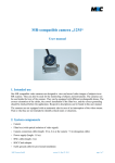
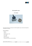
MR-compatible camera “12M-i” with integrated LED light User manual 1. Intended use Our MR compatible cameras are designed to view and record video images of subjects in an MR scanner. They can also be used for the monitoring of objects and instruments. The cameras can be used inside the bore of the scanner. They can be equipped with different exchangeable lenses. The correct orientation of the cables, the correct installation of the filter box, and the correct grounding should be checked before the application. Respective descriptions can be found in this user manual. In the 12M-i models, an LED for different illumination purposes like face monitoring or eye-tracking is integrated. It is based on a single light-emitting-diode (LED) which is embedded in the titanium housing and emits diffuse light. The cameras are not equipped with an automatic alert in case of an interruption of the video stream. That is why they are not intended to identify critical states or situations. MRC Systems GmbH version 3 - May 22, 2015 page 1 of 8 2. System components • Camera • LED • Filter box (with optical isolation of video signal) • Camera connection cable (length: 10 m, 2 m at the camera + 8 m elongation cable) • Power supply (length: 1.8 m) • BNC cable (length: 2 m) • BNC/Cinch adapter • Earth ground cable for provisional installation There are different types of LEDs that can be used with the camera. It is possible to provide both, visible or infrared light. 3. Video camera, lens and LED light Figure 1 shows the camera housing with the LED and a connected lens. connection cable mounting holes LED focus adjustment 12 x 0.5 mm lens mount with lens Figure 1: Video camera with LED and lens The lens is connected to the standard M12 mount in the housing. • The focus adjustment is done by screwing the lens in and out. Care should be taken not to screw out the lens too far, as the lens may fall out of the thread. The LED light is embedded in the camera housing. The distance to the lens is chosen in order to avoid undesired shadowing effects. The device is connected to the filter box via a connection cable which must be plugged into the “MR CAM Signal IN” connector. MRC Systems GmbH version 3 - May 22, 2015 page 2 of 8 4. Mounting options The device can be mounted directly to any suitable object via the two 2 mm holes in the backplate. Standard mounting options are: 1. direct mounting of the camera using the mounting holes 2. use of an articulated arm (optional accessory) for mounting the camera e.g. to the head coil 3. use of a ball joint mount (optional accessory) e.g. for use inside the MR bore 4. use of a tripod adapter (optional accessory) for mounting the camera on a tripod You can find photos of the optional accessories in section 11 of this manual. 5. Connection of camera/LED to filter box The powering of the camera and the LED is arranged via the filter box. The camera/LED is connected to the filter box with the shielded camera connection cable which includes the power and the signal lines. The filter box prevents the transmission of disturbing signals into the MR cabinet. It avoids interferences in the video signals and the MRI imaging. The filter box includes a low pass filter that suppresses frequencies higher than 1 MHz with over 100 dB. This filter prevents damage and interferences caused by the high frequency signals of the MR scanner. In addition, the filter box includes an optical isolation of the video signals. In that way a full separation of the MRI equipment from the external power network is guaranteed. Note: The filter box is only suitable for the camera 12M-i with integrated LED. Connecting the standard 12M or CS camera to the filter box will destroy the integrated electronics! camera connector MRC Systems GmbH Figure 2: Filter box (front side) version 3 - May 22, 2015 page 3 of 8 6. Filter box installation For a permanent installation, the filter box should be screwed onto the panel board by means of the feed through camera connector (see figure 2). Figure 3 illustrates the recommended configuration: • A 12 mm through hole in the panel board is required. • The camera connector is guided through this hole. • The camera connector provides the ground connection to the shielding of the MR cabinet. For temporary use, the camera cable can be brought into the MR cabinet by other means, e.g. through a service entry hole (“waveguide”). In this case, an additional grounding cable should be used to connect the camera connector to the shield panel grounding. The camera connector must completely protrude into the MR cabinet and the video cable must not jut out. Figure 3: Device and cable configuration 7. Connection of power supply, light intensity adjustment The power for the camera is transmitted via the video cable. Therefore, the power supply is connected to the filter box (see figure 4). Next to the video connector is a green “active” signal which shines when the device is powered and the LED on the front side of the camera is turned on. By pushing the button of the “active” signal the LED can be switched off. The intensity of the LED light can be adjusted by means of a potentiometer at the filter box. 7.1. Eye safety The infrared LED in the camera is eye-safe. The peak wavelength is 950 nm. We recommend to keep a distance between the light source and the subject's eye of 50 mm or more. With the white-light LED you should avoid to shine directly in the eye. Please be aware that the lid-closing reflex of babies can be unincisive. MRC Systems GmbH version 3 - May 22, 2015 page 4 of 8 LED intensity adjustment “active” signal video connector power supply Figure 4: Filter box (rear side) 8. Connection of TV set, VCR, frame grabber, or video card A BNC/Cinch adapter and a standard BNC cable are used to transfer the video output signal to a TV set, VCR, frame grabber, or video card. The BNC/Cinch cable is plugged via the adapter to the video connector at the filter box (see figure 4). The video signal can be directly viewed with a TV set or recorded with a VCR. To view and store the images with a PC, the BNC/Cinch cable must be connected to a frame grabber or video card within the PC. Any software for analog video viewing should be appropriate to process the signals. 9. Maintenance and cleaning Light-emitting diodes (LEDs) are subject to an ageing process which is accelerated if the LEDs are driven at highest powers. In order to increase the lifetime of the product we recommend not to drive the light source with highest intensity and to disconnect it from mains whenever it is not in use. The device should be applied in dry environments. It is not sealed against splash water and rinsing liquids. The housing and the lens can be cleaned with a dry cloth. If this is not sufficient, the cloth can be moistened with clear water or alcohol. 10. Technical data Video camera Sensor Type: Output: Sensitivity: MRC Systems GmbH B/W or color CMOS Sensor 1/3 inch EIA(NTSC) video signal with 60 Hz half frame rate or CCIR(PAL) video signal with 50 Hz half frame rate 0.2 Lux for f#1.2 (B/W) version 3 - May 22, 2015 page 5 of 8 Spectral sensitivity (B/W camera) Housing dimensions Dimensions: Connector for lens: Mounting holes: Weight: 27 mm x 18 mm; height 27 mm + lens (without mounting bracket) 12 x 0.5 mm mount two pairs of holes, 2 mm Ø, distance 23 mm 45 g (without cable) LED Spectrum Current: white or infrared (diffused) 10-100 mA Lenses Type: Mount: Focal length: Standard delivery: Aperture: Sensor format: Minimal object distance: fixed focal length with fixed aperture, exchangeable 12 x 0.5 mm a big number of different focal lengths are available focal lengths: 4.3 mm, 6 mm, 8 mm (other lenses on request) e.g. 2.4 1/3 inch 50 mm (typical, depending on the chosen lens) Electronics Power supply: Output impedance: Type: 300 mA, 6 V DC 75 Ω Friwo FW7555M/06, 6 V (medical power supply) Filter box Dimensions: Weight: 80 mm x 120 mm x 80 mm approx. 700 g MRC Systems GmbH version 3 - May 22, 2015 page 6 of 8 11. Camera holders (optional accessories) We offer different camera holders for the MR compatible camera. Examples are shown in the photos below. More information can be found in the specific product descriptions. We can also produce customised solutions. On request, we can offer additional equipment like displays or video cards. Camera holder with ball joint for easy alignment Flexible camera holder based on articulated arm Camera holder at head coil Figure 5: Selection of MR compatible camera holders (The cameras shown in the photos are the standard 12M cameras without integrated LED.) MRC Systems GmbH version 3 - May 22, 2015 page 7 of 8 12. Labelling A label on the camera housing includes the information about the integrated LED (white or infrared) and the embedded video sensor (CCIR or EIA). The following copies are enlarged: MR_CAM Model 12M-i WH-LED SN: 101110HFB129 CCIR MR_CAM Model 12M-i IR-LED SN: 101110HFB129 EIA Supply: 6VDC 300mA Supply: 6VDC 300mA MRC Systems GmbH Hans-Bunte-Str. 10 D-69123 Heidelberg Germany MRC Systems GmbH Hans-Bunte-Str. 10 D-69123 Heidelberg Germany In addition, there is a label on the filter box: MR_CAM Model FIL_LED SN: 101110HFB129 Supply: 6VDC 300mA MRC Systems GmbH Hans-Bunte-Str. 10 D-69123 Heidelberg Germany 13. Contact MRC Systems GmbH Hans-Bunte-Strasse 10 D-69123 Heidelberg Germany phone: +49-6221-13803-00 fax: +49-6221-13803-01 mail: [email protected] MRC Systems GmbH version 3 - May 22, 2015 page 8 of 8