1
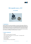
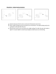
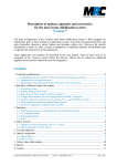
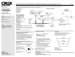
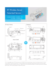
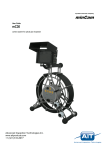
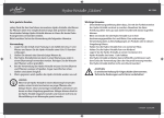
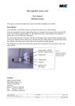
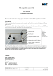
INNOVATIVE TREATMENT SOLUTIONS
MR compatible camera
User manual
This manual describes the essential parts of the MR compatible camera with fixed focal length lens
and illustrates its operation.
System components
•
Camera
•
Filter box
•
Camera connector cable
•
Power supply
•
Cinch cable
•
BNC/Cinch adapter
•
Earth ground cable for provisional installation
MR_CAM_12M-Mount_UserManual_v3.sxw
SF - 11/24/05
version: 3
page 1 of 5
status: approved
INNOVATIVE TREATMENT SOLUTIONS
A. Video camera and lens
Figure 1 shows the camera housing and the connected lens.
The lens is connected to the standard 12mm mount in the housing.
•
The focus adjustment is done by screwing in and out the lens. Care should be taken not to screw
out the lens too far, as the lens may fall out of the thread.
Video cable
Focus
adjustment
Mounting thread
12x0.5mm-lens mount
with lens
Mounting holes
Figure 1:
Video camera and lens
The camera is connected to the filter box via a video cable which must be plugged to the video
connector of the camera cable.
It can be mounted directly to any suitable object via the two 2mm holes in the camera backplate.
B. Camera mount with ball joint (optional)
An other possibility is to mount it to the camera mount (tilting plate) via the M2 mounting thread in
the camera housing (see figure 2). In delivery state the camera is already mounted to the tilting
plate. If you remount the tilting plate, take care on the tiny 2 mm thread. The ball joint should be
connected to the camera only without the tilting plate! So before remounting the ball pin to the
camera the tilting plate should be disassembled to separate the ball pin. You have to screw out the 4
brass screws with a screwdriver. Screw the ball pin into the camera back with care or you will
damage the 1.6mm threads. After the pin is mounted, you can fixate it with pliers carefully and then
reassemble the tilting plate again.
The plate consists of two parts. One part (wall mount) is to be mounted somewhere, then the two
parts can be pushed together. For quick removal the camera can be pulled out the wall mount.
MR_CAM_12M-Mount_UserManual_v3.sxw
SF - 11/24/05
version: 3
page 2 of 5
status: approved
INNOVATIVE TREATMENT SOLUTIONS
Figure 2:
4 screws to disassemble
tilting plate
Application sample:
Camera mounted on
tilting plate
Ball pin
C. Connection of camera to filter box
The camera is connected to a filter box via the camera connector cable, which includes power and
signal lines as well as shielding.
The filter box includes a low pass filter that suppresses frequencies higher than 1MHz with over
100 dB. This filter prevents damage and interferences caused by the high frequency signals of the
MR scanner.
Camera
connector
Figure 3: Filter box (front side)
D. Filter box installation
The filter box should be attached to the panel board of the MR cabinet. It must be placed outside the
MR cabinet. The video cable that connects the filter box with the camera must be brought into the
MR cabinet via a feed-through hole.
For a permanent installation, the filter box should be screwed onto the panel board by means of the
feed through camera connector. Figure 4 illustrates the recommended configuration:
MR_CAM_12M-Mount_UserManual_v3.sxw
SF - 11/24/05
version: 3
page 3 of 5
status: approved
INNOVATIVE TREATMENT SOLUTIONS
•
A 12 mm through hole in the panel board is required.
•
The camera connector is guided through this hole.
•
The camera connector provides the ground connection to the shielding of the MR cabinet.
For temporary use, the camera cable can be brought into the MR cabinet by other means, e.g.
through a service entry hole. In this case, an additional grounding cable should be used to connect
the camera connector to the shield panel grounding.
Figure 4: Device and cable configuration
E. Connection of power supply
The power for the camera is transmitted via the camera connector cable. Therefore, the power
supply is connected to the filter box (see figure 5). The required power values are 200 mA, 6-12V.
Video
connector
Power
supply
MR_CAM_12M-Mount_UserManual_v3.sxw
SF - 11/24/05
version: 3
Figure 5: Filter box (rear side)
page 4 of 5
status: approved
INNOVATIVE TREATMENT SOLUTIONS
F. Connection to TV set / VCR / frame grabber
A BNC/Cinch adapter and a standard Cinch cable are used to transfer the video output signal to a
TV set, VCR, frame grabber, or video card. The Cinch cable is plugged via the adapter to the video
connector at the filter box (see figure 5).
The video signal can be directly viewed with a TV or recorded with a VCR. To view and store the
images with a PC, the Cinch cable must be connected to a frame grabber or video card within the
PC. Any software for analog video viewing should be appropriate to process the signals.
G. Technical Data
Sensor Type:
Output:
Output impedance:
Sensitivity:
Connector for lens:
Supply:
Weight:
Size:
Mounting Thread:
Lens:
Type:
Mount:
Focal length:
Aperture:
Sensor format:
Minimal object distance:
B/W CMOS Sensor 1/3 inch
EIA(NTSC) video signal with 60Hz half frame rate
75Ω
0.2Lux for f#1.2
12x0.5mm Mount.
6 VDC, 200mA
22g
28 mm x 18 mm; height ≈ 23 mm + lens
M1.6, max 2mm depth
fixed focal length with fixed aperture, exchangeable
12x0.5mm
6mm
2.4
1/3 inch
50mm
H. Contact
MRC Systems GmbH
Hans-Bunte-Strasse 10
D-69123 Heidelberg
Germany
phone: +49-6221-13803-00
fax: +49-6221-13803-01
mail: [email protected]
MR_CAM_12M-Mount_UserManual_v3.sxw
SF - 11/24/05
version: 3
page 5 of 5
status: approved