1
MITSUBISHI Electronic Multi-Measuring Instrument
Types
ME110SSR
ME110SSR-4AP
ME110SSR-4APH
ME110SSR-4A2P
ME110SSR-C
ME110SSR-CH
ME110SSR-MB
User’s Manual: Detailed Edition
Before operating the instrument, you should first read thoroughly
this operation manual for safe operation and optimized
performance of the product.
Deliver this user’s manual to the end user.
Check on your delivery
Check the following point as soon as you receive Mitsubishi Electronic Multi-Measuring Instrument :
● The package is in good condition.
● The product has not been damaged during transit.
● The product corresponds to your order specifications.
● This product has the following accessories.
Quantity
Specifications
User’s Manual
(Simplified)
1
A3 size
Attaching nuts
2
Parts name
M5 belleville spring nuts (contained in a bag)
1
Contents
Check on your delivery ······································································································································ 1
Contents ···························································································································································· 2
Safety Precaution ·············································································································································· 4
EMC DIRECTIVE INSTRUCTION ····················································································································· 6
Features ···························································································································································· 7
Operation
1. Display and Button Functions of Each Part ···································································································· 8
2. Function Modes ············································································································································· 10
3. Settings ·························································································································································· 11
3.1 Setting flow Diagram ································································································································ 11
3.2 Setting Menu 1: Setting the Phase Wire Method, Display Pattern, VT/Direct Voltage,
CT Primary Current, and constant for Demand Time ············································································ 13
3.3 Setting Menu 2: Model code, Backlight, and Display Update Time ······················································· 18
3.4 Setting Menu 3: Setting the Bar Graph, Unit Display, Expanded counting, and Harmonics Display ···· 19
3.5 Setting Menu 4: Index Indicator Setting ································································································· 21
3.6 Setting Menu 5: Setting the Upper/Lower Limit Alarm, Backlight Flickers During Alarms and Motor
Startup Current Delay Function ············································································································· 22
3.7 Setting Menu 6: Setting the Analog Output and Pulse Output ······························································· 25
3.8 Setting Menu 7: Setting the Communication ·························································································· 30
Setting Menu 7: Setting the ModBus Communication ··········································································· 31
3.9 Setting Menu 8: Setting the Operating Time Display, CO2 Emission Display,
and Element Information ······················································································································· 32
3.10 Setting Value Confirmation Menu 1: Confirming the Setting Values for Setting Menu 1 ······················· 33
3.11 Setting Value Confirmation Menus 2 to 8: Confirming the Set Values for Setting Menus 2 to 8 ············ 34
3.12 Initializing Related Items by Changing Settings ···················································································· 35
3.13 Initializing All Settings ····························································································································· 35
3.15 Setting the Special Display Pattern P00 ································································································ 36
3.16 Examples of Simple Settings ················································································································· 38
4. Using Test Mode ············································································································································ 40
4.1 Test Menu 1: Incorrect Wiring Determination Support Display ································································ 41
4.2 Test Menu 2: Zero Span Adjustment for Analog Output ·········································································· 43
4.3 Test Menu 3: Analog Output Operation Test ···························································································· 44
4.4 Test Menu 4: Pulse Output Operation Test ······························································································ 45
4.5 Test Menu 5: Alarm Output Operation Test ······························································································ 45
4.6 Test Menu 6: Communication Test ·········································································································· 46
5. Operation························································································································································ 47
5.1 Basic Operations ····································································································································· 47
Switching display ·································································································································· 47
Switching phase ···································································································································· 47
Bar graph display ·································································································································· 48
Switching measurement factors displayed on bar graphs ····································································· 48
Cyclic display ········································································································································ 48
Harmonics display ································································································································· 49
Maximum value and minimum value display ························································································ 50
Display of maximum value and minimum value ···················································································· 50
Clear the maximum/minimum value ····································································································· 50
Active energy and reactive energy display ··························································································· 51
Enlarged 3 digital figures. ······················································································································ 51
Wh and varh zero reset ························································································································ 51
Reactive energy measurement method (2 quadrant / 4 quadrant counting) ········································· 52
Each measurement item display during power transmission ································································ 52
Demand time and demand value ·········································································································· 52
2
Contents
5.2 Usage According to Purpose ··················································································································· 53
Display and operation of the upper/lower limit alarm ············································································ 53
Canceling the upper/lower limit alarm ··································································································· 54
Stopping backlight flickering caused by upper/lower limit alarm generation ········································· 54
Operation time display ························································································································· 54
Clearing the operation time ··················································································································· 54
CO2 emission display ···························································································································· 55
Clearing the CO2 emission value ·········································································································· 55
Display and operation of the digital input status ··················································································· 56
Preventing maximum value update by motor startup current ······························································· 57
Indicator display ···································································································································· 57
6. Other ······························································································································································ 58
6.1 Display Pattern Contents ························································································································· 58
6.2 Maximum Scale Value ····························································································································· 60
6.3 Possible Setting Range for Maximum Scale ··························································································· 62
6.4 Measurement Items and Correspondence between Display and Output ················································ 64
6.5 Measurement Characteristic ··················································································································· 66
6.6 Troubleshooting ······································································································································· 67
7. Warranty ························································································································································ 68
Installation
1. External Dimensions ······································································································································ 69
2. Mounting ························································································································································· 71
3. Wiring ····························································································································································· 72
4. Wiring Diagram ·············································································································································· 74
Specifications
Specification ······················································································································································ 79
Communication Specification ···························································································································· 80
Settings Table (Factory Settings and Customer Setting Note) ·········································································· 81
3
Safety Precaution
(Always read these instructions before using this equipment)
For personnel and product safety please read the contents of these operating instructions carefully before
using.
Please save this manual to make it accessible when required and always forward it to the end user.
CAUTION
Indicates that incorrect handling may cause hazardous conditions. Always follow the
instructions because they are important to personal safety. Otherwise, it could result in
electric shock, fire, erroneous operation, and damage of the instrument.
■Normal service conditions
CAUTION
Use the instrument in an environment that meets the Normal service conditions as following points:
●Ambient temperature :-5 to 50°C, average day temperature: 35°C or lower
●Humidity :30~85%RH, non condensing.
●Altitude: 1000m or less
●Pollution Degree : 2
●Atmosphere without corrosive gas, dust, salt, oil mist.
●A place without excessive shocks or vibration.
●Do not expose to rain and water drips.
●Do not expose to direct sunlight.
●An area where no pieces of metal and no inductive substances disperse.
●Do not expose to strong electromagnetic field and ambient noises.
■Installation instructions
CAUTION
●This instrument should be installed and used by a qualified electrician.
●The instrument must not be powered and used until its definitive assembly on the cabinet’s door.
●Verify the following points;
Auxiliary power supply and Measuring ratings
Voltage
100-240V AC+10-15%(50-60Hz) 10VA
100V DC+40-25% 6W
277V AC phase-neutral / 480V AC phase-phase
Current
Frequency
5A or 1A (via current transformer)
50/60Hz
Auxiliary power supply
Ratings
Current circuits, C1, C2 and C3 are Measurement category .
Voltage circuits, P1, P2 and P3 are Measurement category .
The
● instrument is to be mounted on panel. All connections should be kept inside the cabinet.
●Tighten the terminal screws with the specified torque and use the suitable pressure connectors
and suitable wire size. (see page 72)
●When wiring in the instrument, be sure that it is done correctly by checking the instrument ‘s wiring
diagrams. (see pages 74 to 78)
●Be sure there are no foreign substances such as sawdust or wiring debris inside the instrument.
●Do not drop this instrument from high place. If you drop it and the display is cracked, do not touch
the liquid crystal and get it in your mouth. If touching the liquid crystal, wash it away at once.
●In order to prevent invasion of noise, do not bunch the control wires or communication cables
with the main circuit or power wire, or install them close to each other. The distance between
communicational signal lines, input signal lines and power lines, and high voltage lines when
running parallel to each other are shown below.
Conditions
Below 600V, or 600A power lines
Other power lines
Length
30cm or more
60cm or more
4
■Operation instructions
CAUTION
●When the external terminals are connected to the external equipments, the instrument and the
external equipments must not be powered and used until its definitive assembly on the cabinet’s
door.
●The rating of the terminal of the external equipment should satisfy the rating of the external
terminal of this instrument. (See Specifications.)
■Maintenance instructions
CAUTION
●Do not touch the terminals while all the circuits connected to this instrument are alive.
●Do not disassemble or modify the instrument.
●Do not allow a chemical dust cloth to be in contact with the instrument for a long time, or do not
wipe it with benzene, thinner, alcohol.
●Wipe dirt on surface with a soft dry cloth.
●Check the following points,
Condition of the appearance
Condition of the Display
Unusual sound, a smell, and generation of heat
Condition of the wiring and the attachment
■Storage conditions
●Ambient temperature: -20 to 60°C, average day temperature: 35°C or lower
●Humidity range 30~85%RH, non condensing.
●Atmosphere without corrosive gas, dust, salt, oil mist.
●A place without excessive shocks or vibration.
●Do not expose to rain and water drips.
●Do not expose to direct sunlight.
●An area where no pieces of metal and no inductive substances disperse.
■Disposal
●When disposing of this product , treat it as industrial waste.
●The battery is not used for this product.
■Guarantee
The period of guarantee is for 1 year from the sale date, except in the case that the failure has
been caused by bad handling of the product, provided that it has been installed according to the
manufacture’s instructions.
5
EMC DIRECTIVE INSTRUCTION
This section summarizes the precautions on conformance to the EMC Directive of the cabinet
constructed using this Instrument.
However, the method of conformance to the EMC Directive and the judgment on whether or not the
cabinet conforms to the EMC Directive has to be determined finally by the manufacturer.
1. EMC Standards
●EN 61326-1:2006
●EN 61000-3-2:2006/A1:2009/A2:2009
●EN 61000-3-3:2008
2. Installation (EMC directive)
The instrument is to be mounted on panel of a cabinet.
Therefore, the construction of a cabinet is important not only for safety but also for EMC.
The instrument is examined by the following conditions.
● Use a conductive cabinet.
● Six faces of a cabinet have to be ensured conductivity for each other.
● A cabinet has to be connected to earth by a thick wire of low impedance.
● Holes on faces of cabinet have to be 10 cm or less in diameter.
● The terminals for protective earth and functional earth have to be connected to earth by a thick
wire of low impedance. (A terminal for protective earth is important not only for safety but also for
EMC.)
Protective earth: Maintains the safety of the instrument and improves the noise resistance.
Functional earth: Improves the noise resistance.
● All connections should be kept inside the cabinet.
● Wirings outside the cabinet have to be used with the shielded cable.
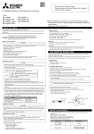
The following diagram shows how to provide good contact of the shielded cable.
Remove part of the outer cover.
Remove part of the paint musk on the cabinet.
Connect those parts with the clamp.
Screw
Clamp fitting
Shield section
Paint mask
Shielded cable
6
Features
This instrument measures the load status by inputting the secondary side of the VT and CT, and
displays various measurement values.
In addition, telemonitoring can be done by a variegated output function.
■Various measurement parameters
Phase wire system
3P4W
3P3W,1P3W
Current
A
A1,A2,A3,AN,Aavg
Current Demand
DA
Voltage
1P2W
A1,A2,A3
A1
DA1,DA2,DA3,DAN,DAavg
DA1,DA2,DA3
DA1
V
V12,V23,V31,Vavg(L-L),
V1N,V2N,V3N,Vavg(L-N)
V12,V23,V31
V12
Active Power
W
ΣW,W1,W2,W3
ΣW
ΣW
Active Demand Power
DW
ΣDW,DW1,DW2,DW3
ΣDW
ΣDW
Reactive Power
var
Σvar,var1,var2,var3
Σvar
Σvar
Apparent Power
VA
ΣVA,VA1,VA2,VA3
-
-
Power Factor
cosφ
Σcosφ,cosφ1,cosφ2,cosφ3
Σcosφ
Σcosφ
Frequency
Hz
Hz
Active Energy
Wh
Import, Export
Reactive Energy
varh
Import lag, Import lead, Export lag, Export lead
Harmonic Current
HI
Harmonic Voltage
HV
HI1, HI2, HI3, HIN
HI1,HI3
HI1
THD,h1...h13(without even number)
RMS value and Distortion ratio(max.100%)
HV1N,HV2N,HV3N
HV12,HV23
HV12
THD,h1...h13(without even number)
RMS value and Distortion ratio(max.20%)
Referred to as follows in this manual:
average value : avg
three phase total RMS : Σ
phase to phase : L-L
phase to neutral : L-N
ex) average value of current : Aavg
Three phase active power : ΣW
1-phase to 2-phase voltage : V12
1-phase to neutral voltage : V1N
■4 measurement items appear on one display
By combination of bar graph and digital 3-stage display, 4 measurement items can be displayed on
one display. For example, voltage, current, power factor and active power can be displayed at the
same time.
■RS485 interface, ModBus RTU(ME110SSR-MB)
■CC-Link communication
Measured values can be sent to PC or PLC via CC-Link communications. (ME110SSR-C,-CH)
■Analog 4 outputs + pulse output + alarm relay output (ME110SSR-4APH)
For example, the analog outputs of voltage, current, active power, and power factor, the pulse
output of active energy, and the alarm output of THD can be performed by one unit.
■Harmonics
It is equipped with harmonics current and harmonics voltage measurement function as standard
one.
■Back light auto off function
It is equipped with energy saving mode function where the back light is turned off when there is no
key operation for 5 minutes.
7
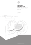
Operation 1. Display and Button Functions of Each Part
1
14
2
■ Display
3
4
5
6
8
7
9
11
10
12
13
15
16
17
18
Note: The above display is an example for explanation.
No.
Segment Name
Description
1
LEAD status
Shows direction power factor or reactive power on bar graph.
2
LAG status
Turns on at the additional display of reactive energy.
3
Scale of the bar graph
Shows the scales at the bar graph.
4
Under scale input
Turns on when measuring values fall below the minimum scale.
5
Over scale input
Turns on when measuring values exceed the maximum scale.
6
Alarm indicator
When upper/lower limit alarm set, flickers at the limit setting value.
7
Index indicator
When set, turns on at the index indicator setting value.
8
Bar graph status
Shows the item displayed on the bar graph.
When the item is the same as a digital displayed item,indicated with “
”,
”
otherwise indicated with “
9
Digital status
Phase status, “123N” , “MAX/MIN”,demand etc. displayed.
10
Digital display
Measured values displayed in digital.
11
Units
Units of measuring value displayed.
12
Multiplying factor
Indicates the multiplying factor for calculating energy.
13
Metering status
Flickers when counting active energy.(Note.1)
14
Harmonics
Turns on when harmonics displayed.
15
Setup mode status
Turns on at setting mode.
Flickers at setting value confirmation mode.
16
Test mode status
17
Upper/lower limit alarm status Flickers when upper/lower limit alarm is generated.
Turns on at the test mode.
The following are displayed for models with a transmission function.
Model
ME110SSR-C
18
Communication status
ME110SSR-CH
ME110SSR-MB
On
Normal
Normal
Blinking
・CC-Link compatible version mismatch
・Hardware error
・Communication error (Such as
wrong address)
* Products other than above don’t illuminate.
Note 1. The blinking cycle is constant regardless of the size of the measured input.
8
Off
Hardware error
Hardware error
5. Operation
Operation
1. Display and Button Functions of Each Part
■ Functions of operation buttons
SET
The operation button have various functions
according to how they are pressed down.
RESET
+/– key
Meaning of code:
Mode
(Press),
(press over 1 second),
(press over 2 seconds),
PHASE
DISPLAY
Reset key
Set key
Operation
MAX/MIN
(press simultaneously)
Phase change
key
Maximum/minimum Display change
key
key
Key name
SET
RESET
Max/
Min
Function
PHASE DISPLAY
Display changes.
Phase changes.
BASIC
Mode changes to the max./min. display and the instantaneous
display
The item expressed with the bar graph is changed.
Harmonics number changes when harmonics displayed.
Displays change cyclically. (Refer to page 48)
Phases change cyclically. (Refer to page 48)
Operation mode
The counting values of three digits of low rank are displayed.
After pressing once again, the display returns. (Refer to page 51)
Maximum values and minimum values on
the display are reset to the present value.
All of the Maximum values and minimum
values are reset to the present value.
Only available for
maximum/minimum
value screen
Special
All of the counting values are zero reset.
The operation time is zero veset (Screen operation time only)
An alarm condition is canceled.
(Screen element is canceled)
All alarm conditions are canceled.
(Element is canceled for all screens)
Available only when
manual cancelation
is set
Setting Operation
The display of Set value confirmation mode appears.
The display of Setup mode appears.
The set-up items are saved, and set-up item is changed to next
item.
Back to the previous item.
The values of set-up is changed.
(If it presses for 1 sec or more fast forward or fast return.)
Back to the Setup display.
Special Operation
Set-up mode/
Set value confirmation mode
Mode
Switch
The latching data of digital input on the display is canceled.
(Available only for contact point input screen)
Returns from infrared mode to operation mode (Available only for
infrared mode)
Back to the Setup display.
Returns set contents to the default settings
(Only effective in CANCEL display) (Refer to page 35)
Note: While the back light is off, if the operation key is pressed, the back light is always lit. If the operation button
is pressed once again, the function in the above table appears.
Note: When Wh and varh are cleared to zero, the CO2 emission value is also cleared.
CAUTION
If the function of “maximum value and minimum value reset” and “Wh, varh zero reset”
are done,data will be lost. If this data is needed,please record the data before the reset
operation.
If the function of “meter restart” is done, the entire measurement(measure-ment display,
alarm, analog output, pulse) stops.
9
5. Function
OperationModes
2.
The following function modes are available for this Multi-Measuring instrument. Operation mode is displayed after
auxiliary power turns on. It is then possible to switch to the desired mode.
Mode
Reference
Pages
Description
P. 47 to P. 57
Operation Mode
This mode is for displaying each measured value using digital numerical
values and bar graphs.
Operation mode contains "Current Value Display" that displays the current
value, and "Maximum/Minimum Value Display" that displays old maximum/
minimum values.
In addition, for each display, the cyclic display function can be used to switch
between the screens every 5 seconds.
Setting mode
This mode is for changing the setting values related to measurement and
P. 12 to P. 32
output functions.
P. 35 to P. 39
The following special operations can be executed from the "CANCEL Display"
for changing/cancelling setting values.
The instrument is reset.
Reset the settings to the factory defaults (Note)
Setting value
confirmation mode
This mode is for confirming the setting values for each setting item.
(In this mode, settings cannot be changed in order to prevent accidental
changing of settings.)
This mode contains test functions that can be used for equipment startup.
Incorrect Wiring Determination Support Display
: This displays information such as voltage and
current phase angle display for determining
improper wiring.
Analog Output Adjustment : Analog output can be adjusted (zero adjustment
and span adjustment).
Output Test
: Analog output can be switched, pulse output
can be executed, and alarm contact points can
be opened/closed without measurement input
(voltage/current).
Communication Test
: Fixed numerical data can be returned without
measurement input (voltage/current).
P. 33 and P. 34
P. 40 to P. 46
Note: When the purchased product already has settings, the setting values will not longer be available after
this operation.
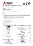
■ Diagram of Each Mode
Pressing SET
+ RESET simultaneously for 2 seconds
SET
END
Display
Operation mode
Save the settings
+
SET
,
-
When "End" is selected
from the menu
SET
Current value
display
Maximum/minimum
value display
CANCEL
Display
Cancel the settings
SET
Setting mode
SET
Press for 2 seconds
SET
SET
When "End" is selected
from the menu
Setting value
confirmation mode
Test function
10
3. Settings
3.13.1
Setting
fl
Procedure
ow
Setting
Procedure
To measure, it is necessary to use Setting mode to set the phase wire system, VT / direct voltage, and CT
primary current.
From Operation mode, move to Setting mode and then set necessary items. Factory default settings will be used
for items that you do not set.
Only the settings in Setting menu 1 (basic set-up) are needed for normal use. For more information about the
settings, refer to the following pages.
For more information about the factory default settings, refer to the setting table on page 81.
Operation Mode
Setting Menu End
Setting Menu 1 (Basic Set up)
Setting Menu 2
Setting Menu 3
㶎㪈
END Display
Save the setting.
Cancel
Display
wire system
Model + Option
code
Current
maximum scale
Display
Pattern
Backlight
brightness
Active
power maximum
scale
VT/direct
voltage
Backlight
auto off
Active
power unit
W/kW/MW
Primary
current
Display
update time
Phase
Reactive power
maximum scale
Cancel the settings.
Time constant for
active power demand
Automatic migration.
Factory default
setting
Time constant for
current demand
㪕
Menu 1
for Setting Value
Confirmation Mode
㪕
Reactive
power unit
Model display
+
Option display
Expanded
counting
Phase wire system
+
Display pattern
Harmonics
VT secondary voltage
+
VT primary voltage
Example of Setting Mode
Example of Setting Value
Confirmation Mode
CT secondary current
+
CT primary current
Time constant for
active power demand
Time constant for
current demand
ON
CAUTION
Blinking
Keep in mind that when a setting is changed, the related setting items and measurement data
will be reset to the default settings.
(Refer to page 35.)
11
3. Settings
3.1 Setting flow
<Setting Procedure>
Press
SET
and
RESET
simultaneously for 2
up menu and press
seconds to get in the set-up mode.
Select a set-up menu number by
Use the
SET
SET
.
When the End display appears, press
or
.
SET
once
again.
key to select a set-up menu number.
Set each setting item. (Refer to page 14 and later
pages.)
After completion of set-up, select ‘End’ in the setSetting Mode or Setting Value Confirmation Mode
Setting Menu 4
Setting Menu 5
Setting Menu 7
Setting Menu 6
Setting Menu 8
Setting Value Confirmation Menu 9
㶎㪌
Indicator
item
Alarm item
㶎㪉
㶎㪉
Indicator
value
Enable/disable
operation time display
Analog output
1
Test Mode
㶎㪊
Alarm value
Analog output
2
Alarm delay
time
Analog output
3
Alarm cancel
method
Analog output
4
Enable/disable
CO2 display
㶎㪊
Switch element
information
㶎㪊
CC-Link
station number
ModBus
address
CC-Link
baud rates
ModBus
baud rates
Power data
resolution
ModBus
parity
CC-Link
version
ModBus
stop bit
CC-Link
module reset
ModBus
module reset
㶎㪊
Back light flickers
during alarms
Analog output
Limit
Motor starting
current delay time
Pulse output
㶎㪊
㶎㪊
Digital
input setting
㶎㪋
Digital input
cancel methad
㶎㪋
ME110SSR-C
ME110SSR-CH
㶎1: For Setting Value Confirmation, it returns to Operation Mode.
㶎2: Repeat settings for up to 4 elements.
㶎3: Setting is only possible for ME110SSR-4AP,4APH and -4A2P.
㶎4: Setting is only possible for ME110SSR-CH.
㶎5: This is not display in Setting Mode.
Arrow in Figure
<ME110SSR-MB>
Key operation
Action
SET 䋫 RESET
Press them simultaneously
for 2 seconds.
Shift from the operation mode to the set value
confirmation mode.
SET
Press it for 2 seconds.
Select the menu number to set or “End” .
䋫 or 䋭
Press it several times.
Shift from the operation mode to the set-up mode.
Get into each setting screen.
Shift to the next setting item.
Go back to the previous setting item.
Omitted in
Select a set value.
figure
Press it.
DISPLAY
Press it.
䋫 or 䋭
Press it several times.
Shift to the End screen.
SET
Press it.
Memorize the setting contents, and go back to
the operation mode.
SET
Press it.
䋫 or 䋭
Press it.
Select "CANCEL."
Cancel the settings.
Skip remaining setting items during setting.
Set values return to the factory default value.
12
SET
SET
Press it.
SET
Press it for 1 second
RESET 䋫 PHASE Press it for 2 seconds
5. Settings
Operation
3.
■ Basic Operations for set-up
Function
Operation
Remarks
Select a set value
Press
Set-up items are saved
Press
SET
Go back to the previous setting item
Press
DISPLAY
Skip removing setting items
Press and hold
during setting
for 1 sec.
or
.
Fast-forward when pressed over 1 sec.
.
Set-up item will be cared and shift to the next item.
.
The set value for the setting item just before
SET
returning is still available.
This
section
is about
setting
the phase
wire method,
display
pattern,
VT/direct
voltage,
CTand
primary
current,
3.2 Setting
Menu
1: Setting
the Phase
Wire System,
Display Pattern,
VT/Direct
Voltage,
CT Primary
Current,
Time constant
forand
Demand
In the operation mode, after pressing
operation becomes available.
and
SET
RESET
simultaneously for 2 seconds or more, the following
Set the setting menu number to “1”.
Setting Menu
DISPLAY SET
㽲㩷 Phase㩷 Wire system
Set the phase wire system.
2CT
3CT
1N2
1N3
3P4
3P3
3P3
1P3
1P3
1P2
: Three-phase 4-wire
: Three-phase 3-wire (2CT)
: Three-phase 3-wire (3CT)
: Single-phase 3-wire (1N2)
: Single-phase 3-wire (1N3)
: Single-phase 2-wire
Supplemental Information:
Underlined portions indicate
the default values.
(Same from here.)
Set the display pattern.
DISPLAY SET
The following table shows the measurement elements that can be
displayed by each display pattern. (For more details about display
patterns, refer to page 62.)In addition, if there is no display pattern that
you want from P01 to P13 (P14 and P15), select the special display
pattern P00 to configure the screen freely.(For more information about
setting the special display pattern P00.)
䂾 : Displayable at this display setting.
䂦 : Set at other additional settings.
䂔 : Select "P00" and set the display order and display position.
(a) For three-phase 4-wire
䂦㩷
䂦㩷
䂦㩷
䂦㩷
䂦㩷
䂦㩷
䂦㩷
䂦㩷
䂦㩷
䂦㩷
䂦㩷
䂦㩷
䂦㩷
䂦㩷
䂦㩷
䂦㩷
䂦㩷
䂦㩷
䂦㩷
䂦㩷
䂦㩷
䂦㩷
䂦㩷
䂦㩷
䂦㩷
䂦㩷
䂦㩷
䂦㩷
CO2 Emission㩷
䂦㩷
䂦㩷
䂦㩷
䂦㩷
䂦㩷
䂦㩷
䂦㩷
䂦㩷
䂦㩷
䂦㩷
䂦㩷
䂦㩷
䂦㩷
䂦㩷
Operation time㩷
䂦㩷
䂦㩷
䂦㩷
䂦㩷
䂦㩷
䂦㩷
䂦㩷
䂦㩷
䂦㩷
䂦㩷
䂦㩷
䂦㩷
䂦㩷
䂦㩷
Digital input㩷
(DI1 to DI3)㩷
䂦㩷
䂦㩷
䂦㩷
䂦㩷
䂦㩷
䂦㩷
䂦㩷
䂦㩷
䂦㩷
䂦㩷
䂦㩷
䂦㩷
䂦㩷
䂦㩷
Harmonic voltage㩷
㩷
㩷
㩷
䂦㩷
㩷
㩷
㩷
㩷
㩷
㩷
㩷
㩷
䂦㩷
䂦㩷
N Phase Harmonic Current㩷
㩷
䂦㩷
㩷
䂦㩷
㩷
㩷
㩷
䂦㩷
㩷
㩷
䂦㩷
䂦㩷
䂦㩷
䂦㩷
Harmonic current㩷
㩷
㩷
䂾㩷
䂾㩷
䂾㩷
㩷
㩷
㩷
㩷
㩷
㩷
㩷
䂾㩷
䂔㩷
Reactive Energy㩷
(Special)
Active Energy
(Exported)㩷
㩷
㩷
㩷
䂾㩷
㩷
㩷
㩷
㩷
㩷
㩷
㩷
㩷
䂾㩷
䂔㩷
Apparent power㩷
㩷
䂾㩷
㩷
䂾㩷
㩷
㩷
㩷
䂾㩷
㩷
㩷
䂾㩷
䂾㩷
䂾㩷
䂔㩷
㩷
㩷
㩷
䂾㩷
䂾㩷
䂾㩷
㩷
㩷
㩷
㩷
㩷
㩷
㩷
䂾㩷
䂔㩷
Reactive Energy㩷
㩷
㩷
䂾㩷
䂾㩷
䂾㩷
㩷
㩷
㩷
㩷
㩷
㩷
㩷
䂾㩷
䂔㩷
Active Energy㩷
䂾㩷
䂾㩷
䂾㩷
䂾㩷
䂾㩷
㩷
㩷
㩷
㩷
㩷
㩷
㩷
䂾㩷
䂔㩷
Frequency㩷
㩷
㩷
㩷
㩷
㩷
㩷
㩷
㩷
㩷
㩷
㩷
㩷
㩷
䂔㩷
Reactive power㩷
䂾㩷
䂾㩷
䂾㩷
䂾㩷
䂾㩷
㩷
䂾㩷
䂾㩷
㩷
䂾㩷
㩷
䂾㩷
䂾㩷
䂔㩷
Power factor㩷
䂾㩷
䂾
䂾㩷
䂾㩷
㩷
䂾㩷
䂾㩷
䂾㩷
䂾㩷
䂾㩷
䂾㩷
䂾㩷
䂾㩷
䂔㩷
Active demand Power㩷
䂾㩷
䂾㩷
䂾㩷
䂾㩷
㩷
䂾㩷
䂾㩷
䂾㩷
䂾㩷
䂾㩷
䂾㩷
䂾㩷
䂾㩷
䂔㩷
Active Power㩷
㩷
㩷
㩷
㩷
㩷
㩷
㩷
㩷
䂾㩷
䂾㩷
䂾㩷
䂾㩷
㩷
䂔㩷
Phase Voltage㩷
㩷
㩷
㩷
㩷
㩷
㩷
㩷
㩷
䂾㩷
䂾㩷
䂾㩷
䂾㩷
㩷
䂔㩷
Line Voltage㩷
䂾㩷
䂾㩷
䂾㩷
䂾㩷
㩷
䂾㩷
䂾㩷
䂾㩷
䂾㩷
䂾㩷
䂾㩷
䂾㩷
䂾㩷
䂔㩷
N Phase demand Current㩷
䂾㩷
䂾㩷
䂾㩷
䂾㩷
㩷
䂾㩷
䂾㩷
䂾㩷
䂾㩷
䂾㩷
䂾㩷
䂾㩷
䂾㩷
䂔㩷
demand current㩷
P01㩷
P02㩷
P03
P04
P05㩷
P06㩷
P07㩷
P08㩷
P09㩷
P10㩷
P11㩷
P12㩷
P13㩷
P00
N phase current㩷
Current
DISPLAY SET
Display Pattern㩷
㽳 Display Pattern
㩷
Additional Screen (Supplemental)
䂦㩷
䂦㩷
䂦㩷
䂦㩷
䂦㩷
䂦㩷
䂦㩷
䂦㩷
䂦㩷
䂦㩷
䂦㩷
䂦㩷
䂦㩷
䂦㩷
Harmonic current / Harmonic voltage
Contact point input status (DI1 to DI3)
Set-up Menu 3
Set-up Menu 7
Reference Pages
Setting item
Electric energy Transmission power display
Page 20
Harmonics display
Page 20
Digital input setting
Page 30
Operation time
Set-up Menu 8
Operation time display
Page 32
CO2 emission
Set-up Menu 8
CO2 emission display
Page 32
Measurement element on additional screen
Electric energy Power sending / reactive electric energy Special Set-up Menu 3
13
3. Settings
3.2 Setting Menu 1: Setting the Phase Wire System, Display Pattern, VT/Direct Voltage, CT Primary Current, and Time
constant for Demand
(b) For other phase wire system except three-phase 4-wire
䂔㩷
䂾㩷
䂔㩷
䂔㩷
䂦㩷
䂦㩷
䂦㩷
㩷
䂦㩷
䂦㩷
䂦㩷
䂦㩷
䂦㩷
䂦㩷
䂦㩷
䂦㩷
䂦㩷
䂦㩷
䂦㩷
䂦㩷
䂦㩷
䂦㩷
䂦㩷
䂦㩷
䂦㩷
䂦㩷
䂦㩷
䂦㩷
CO2 Emission㩷
䂾㩷
䂦㩷
䂦㩷
䂦㩷
䂦㩷
䂦㩷
䂦㩷
䂦㩷
䂦㩷
䂦㩷
䂦㩷
䂦㩷
䂦㩷
䂦㩷
䂦㩷
䂦㩷
䂦㩷
Operation time㩷
䂾㩷
䂾㩷
䂾㩷
䂦㩷
䂦㩷
䂦㩷
䂦㩷
䂦㩷
䂦㩷
䂦㩷
䂦㩷
䂦㩷
䂦㩷
䂦㩷
䂦㩷
䂦㩷
䂦㩷
䂦㩷
䂦㩷
Digital input㩷
(DI1 to DI3)㩷
䂔㩷
䂾㩷
䂦㩷
䂦㩷㩷
䂦㩷㩷
䂦㩷㩷
䂦㩷㩷
䂦㩷㩷
䂦㩷㩷
䂦㩷㩷
䂦㩷㩷
䂦㩷㩷
䂦㩷㩷
䂦㩷㩷
䂦㩷㩷
䂦㩷㩷
䂦㩷㩷
䂦㩷㩷
䂦㩷㩷
Harmonic voltage㩷
䂾㩷
䂾㩷
㩷
㩷
㩷
㩷
㩷
䂦㩷
㩷
䂦㩷
㩷
㩷
㩷
䂦㩷
Harmonic current㩷
䂾㩷
㩷
㩷
Reactive Energy㩷
(Special)
Active Energy
(Exported)㩷
䂾㩷
䂾㩷
䂾㩷
䂾㩷
䂔㩷
㩷
䂾㩷
䂾㩷
䂾㩷
䂾㩷
㩷
䂾㩷
䂾㩷
䂾㩷
䂔㩷
Reactive Energy㩷
Active Energy㩷
䂾㩷
䂾
䂾
䂾
䂔㩷
Frequency㩷
䂾㩷
䂾㩷
䂾㩷
䂾㩷
䂾㩷
䂾㩷
Reactive power㩷
䂾㩷
䂾㩷
䂾㩷
䂾㩷
䂾㩷
㩷
䂾㩷
䂾㩷
㩷
䂾㩷
㩷
䂾
䂾
䂾
䂾
䂔
Power factor㩷
䂾㩷
䂾㩷
䂾㩷
䂾㩷
㩷
䂾
㩷
䂾㩷
䂾㩷
Active demand Power㩷
Voltage㩷
䂾
㩷
䂾
㩷
䂾
㩷
䂾
㩷
㩷
㩷
䂾
㩷
䂾
䂾
㩷
䂾
䂾
䂾
䂾
㩷
䂾
䂾
㩷
䂾
䂔㩷
Active Power㩷
㩷
㩷
㩷
㩷
㩷
㩷
㩷
㩷
䂾
䂾
䂾
䂾
㩷
㩷
㩷
䂔㩷
N Phase demand Current㩷
Current
䂾㩷
䂾㩷
䂾㩷
䂾㩷
㩷
䂾㩷
䂾㩷
䂾㩷
䂾㩷
䂾㩷
䂾㩷
䂾㩷
䂾㩷
䂾㩷
䂾㩷
䂔㩷
Femand current㩷
Display Pattern㩷
P01㩷
P02㩷
P03
P04
P05㩷
P06㩷
P07㩷
P08㩷
P09㩷
P10㩷
P11㩷
P12㩷
P13
P14
P15
P00
Additional Screen (Supplemental)
䂦㩷
䂦㩷
䂦㩷
䂦㩷
䂦㩷
䂦㩷
䂦㩷
䂦㩷
䂦㩷
䂦㩷
䂦㩷
䂦㩷
䂦㩷
䂦
䂦㩷
䂦
Note: The following settings are required for displaying elements on㩷an additional screen.
Setting item
㩷 screen
Measurement element on additional
㩷
Active Energy(Exported) / Reactive(Special)
Harmonic current / Harmonic voltage
Digital input (DI1 to DI3) 㩷
Operation time
CO2 emission
Reference Pages
Setting Menu 3㩷䃂 Expanded
㩷
counting
Setting Menu 3㩷䃂 Harmonics
㩷
Display
㩷
Setting Menu 7㩷 䃂 Digital
input setting
㩷
Setting Menu 8㩷 䃂 Operation
time display
㩷 2 emission display
Setting Menu 8㩷 䃂 CO
When using VT㹢 Select yES, and then press
SET
Page 20
Page 20
Page 30
Page 32
Page 32
, shift to following (1)
㩷 㩷 press 㩷 SET , shift to following (2).
When direct input (without VT) 㹢 Select no, and then
yES
<When 㽲㩷phase wire system is set to single-phase
㩷
3-wire>
Use only for direct input.
㩷
This set-up will be skipped and the setting starts from
ԛ Primary Current .
The rating voltage between P1-P2 or P2-P3 is 110V.
It is 220V between P1-P3
no
㩷
(1) When using VT
Set the secondary and primary voltages of the VT.
(a) For three-phase, 4-wire
<Secondary Voltage (Phase to phase Voltage) Setting Range>
VT / direct voltage
63.5V
100V
110V
115V
120V
<Primary Voltage (Phase to phase Voltage) Setting>
(Default Value: 200V)
DISPLAY SET
䊶 From top digit, select the value of the flickering digit by
䋫 and 䋭 .
䊶 The setting digit can be moved to right by 㪪㪜㪫 .
䊶 The setting digit can be moved to left by DISPLAY .
䊶㩷Setting is available in range from 60 to 750000V.
Less than 100V : Upper 2 digits setting
Over 100V
: Upper 3 digits setting
* Error display (E05) appears when set out of 60 to
750000V range. After that, please press SET , review the
setting value and set it once again.
Press SET at the lowest digit, the setting step will shift to
the next one.
14
DISPLAY SET
To
CT primary current
3. Settings
3.2 Setting Menu 1: Setting the Phase Wire System, Display Pattern, VT/Direct Voltage, CT Primary Current, and Time
constant for Demand
(b) For three-phase 3-wire (2CT, 3CT)
or single-phase 2-wire
<Secondary Voltage Setting Range>
100V
110V
220V
DISPLAY SET
<Primary Voltage Setting Range>
220V
440V
690V
1100V
1.1kV
2200V
2.2kV
3300V
3.3kV
6600V
6.6kV
11kV
13.2kV
13.8kV
15kV
16.5kV
22kV
24kV
33kV
66kV
77kV
110kV
132kV
154kV
187kV
220kV
275kV
380kV
500kV
550kV
SP.
DISPLAY SET
Note: If there is no primary voltage in the above that you want to
set, select "SP." for a special primary voltage setting.
Setting except "SP."䋺 To 㽵 CT Primary Current
When setting "SP." 䋺 To following "Special Primary Voltage"
"Special Primary Voltage" Settings
(Default value: 10,000V)
From top digit, select the value of the flickering digit by
䋫 and 䋭 .
The setting digit can be moved to right by 㪪㪜㪫 .
The setting digit can be moved to left by DISPLAY .
Setting is available in range from 60 to 750000V.
Less than 100V : Upper 2 digits setting
Over 100V
: Upper 3 digits setting
*ޓError display (E05) appears when set out of 60to
ޓ750000V range. After that, please press SET , review
the setting value and set it once again.
Press SET at the lowest digit, the setting step will shift to
ޓthe next one.
DISPLAY SET
To
CT primary current
(2) For direct input (without VT)
Set the direct voltage.
(a) For three-phase 4-wire
(phase to neutral voltage / phase to phase voltage)
63.5/110V
100V/173V
110V/190V
220V/380V
240V/415V
254V/440V
(b) For three-phase 3-wire (2CT, 3CT) or single-phase 2-wire
110V
220V
15
277V/480V
3. Settings
3.1 Setting
SettingMenu
Procedure
3.2
1: Setting the Phase Wire System, Display Pattern, VT/Direct Voltage, CT Primary Current, and Time
constant for Demand
(a) For three-phase 4-wire
Primary Current Setting
(Default Setting: 5A)
From top digit, select the value of the flickering digit by
䋫 and 䋭 .
The setting digit can be moved to right by the SET .
The setting digit can be moved to left by the DISPLAY .
Setting is available in range from 1.0A to 30000.0A
Less than 10A : Upper 2 digits setting
Over 10A
: Upper 3 digits setting
* Error display (E05) appears when set out of 1.0 to 30000.0A
range. After that, please press SET , review the setting value
and set it once again.
Press SET at the lowest digit, the setting step will shift to
To
the next one.
DISPLAY SET
Time constant for
Active power demand
(b) For other phase wire system except Three-phase 4-wire
Set the primary current of the CT you want to combine.
CT primary current
1A
5A
6A
7.5A
8A
10A
12A
15A
20A
25A
30A
40A
50A
60A
75A
80A
100A
120A
150A
200A
250A
300A
400A
500A
600A
750A
800A
1000A
1k A
1200A
1.2kA
1500A
1.5kA
1600A
1.6kA
2000A
2kA
2500A
2.5kA
3000A
3kA
4000A
4kA
5000A
5kA
6000A
6kA
7500A
7.5kA
8000A
8kA
10kA
12kA
20kA
25kA
30kA
SP. Note 1
DISPLAY SET
Note 1: If there is no primary current in the above that you want to set,
select "SP." for special primary current setting.
Setting except “SP” : To ԜTime constant for Active power demand
When setting “SP” : To following “Special Primary Current”
DISPLAY SET
"Special Primary Current" Settings
(Default Setting: 5A)
From top digit, select the value of the flickering digit by
䋫 and 䋭 .
The setting digit can be moved to right by the SET .
The setting digit can be moved to left by the DISPLAY .
Setting is available in range from 1.0A to 30000.0A
Less than 10A : Upper 2 digits setting
Over 10A
: Upper 3 digits setting
* Error display (E05) appears when set out of 1.0 to 30000.0A
range. After that, please press SET , review the setting value
and set it once again.
Press SET at the lowest digit, the setting step will shift to
the next one.
To
16
DISPLAY SET
Time constant for
Active power demand
3. Settings
3.2 Setting Menu 1: Setting the Phase Wire System, Display Pattern, VT/Direct Voltage, CT Primary Current, and Time
constant for Demand
ԡ Set up the time constant for active power demand.
Time constant for
active power demand
DISPLAY SET
0 second
40 seconds
3 minutes
7 minutes
15 minutes
10 seconds
50 seconds
4 minutes
8 minutes
20 minutes
20 seconds
1 minute
5 minutes
9 minutes
25 minutes
30 seconds
2 minutes
6 minutes
10 minutes 30 minutes
Note) Even when the display pattern not display the active power demand,
this screen appears. If the active power demand is not necessary, press the
SET
ޓas it is.
ԢSet the time constant for current demmand.
Time constant
for current demand
SET
0 second
40 seconds
3 minutes
7 minutes
15 minutes
10 seconds
50 seconds
4 minutes
8 minutes
20 minutes
20 seconds
1 minute
5 minutes
9 minutes
25 minutes
30 seconds
2 minutes
6 minutes
10 minutes
30 minutes
Note) Even when the display pattern not display the current demand, this screen
appears. If the current demand is not necessary, press the SET
ޓas it is.
According to the setting flow (page 11), save the changed
contents, or continue to the other set-up menu.
Set-up menu
In the case of use only by the Setting menu 1, please go to “5. Operation” in page 47.
In the case to use additional functions, please go to “Setting Menus 2 - 8” (from page 18 to 32).
Note
If the contents in the setting menu 1 are changed, the maximum value, minimum value,
demand value of related measurement items will be reset.
(However, active energy and reactive energy will not be reset.)
17
5. Settings
Operation
3.
3.2 Setting
3.3
SettingMenu
Menu12: Model code,Backlight,Display Update Time Setting
This section is for confirming model and set the backlight and the display update time. (These settings are not
needed for normal use.)
In the operation mode, press
becomes available.
SET
+
RESET
simultaneously for 2 seconds or more, and the following operation
Set the set-up menu number to “2”.
Setting menu
The model can be confirm. (This is only display, and settings cannot be
changed.)
DISPLAY SET
Display information
Middle Line Lower Line
Blank
Model
ME110SSR
ME110SSR-4AP
ME110SSR-4APH
Model + option code
ME110SSR-4A2P
ME110SSR-C
ME110SSR-CH
ME110SSR-MB
<Note>
Analog output specification is
displayed only for models with
analog output.
A: Current specification (4-20mA)
DISPLAY SET
The backlight brightness can be adjusted.
Backlight brightness
1
2
Dark
DISPLAY SET
Backlight auto off
3
4
5
Bright
The backlight can be set to continuous on (HoLd)
or auto off (Auto).
HoLd
Auto
Continuous on Auto off
<When auto off (Auto) is selected>
No button operation for 5 minutes → the backlight turns off
Button operation during off (Note) → the backlight turns on
for 5 minutes
Note: At this moment, the display is
not changed. When the operation button
is pressed once again, the display is
changed.
DISPLAY SET
Display update time
The display update time for the measured value can be change.
If the display switches too quickly for you to read the displayed
value, set it to 1.0 second.
(Normally, leave this setting to 0.5 second.)
0.5 second
1 second
SET
According to the setting flow (page 11), save the changed
contents, or continue to the other setting menu.
Seting menu
18
5. Settings
Operation
3.
3.4 Setting Menu 3: Setting the Bar Graph, Unit Display, Expanded counting, and Harmonics Display
In this setting menu, you can do in detail set up for the bar-graph, unit, expanded counting, harmonics.
In the operation mode, press
becomes available.
SET
and
RESET
simultaneously for 2 seconds or more, and the following operation
Set the set-up menu number to "3".
Setting menu
DISPLAY SET
Current maximum
scale
Set the current maximum scale.
+3 STEP (About 120%)
to
±0 STEP (100%: Rating)
to
-10 STEP (About 40%)
Note: The maximum scale value becomes the value in the table on page 62.
DISPLAY SET
Set the maximum scale of Active power, active power demand.
(1) Maximum scale value
Active power
maximum scale
+3 STEP (About 120%)
to
±0 STEP (100%: Rating)
to
-18 STEP (About 20%)
Note: The maximum scale value becomes the value in the table
on page 63.
DISPLAY SET
(2) single deflection / double deflection
DISPLAY SET
single deflection
double deflection
Set Active power unit (W, kW, and MW).
Maximum scale value
Active power unit
1,000W or higher
Setting range
8,000W or less
1,000kW or higher 8,000kW or less
DISPLAY SET
Reactive power
maximum scale
W
kW
kW
MW
Note: The unit cannot be changed beyond the above range.
Set the single deflection / double deflection of reactive power.
Single deflection is the LEAD polarity. (The default setting is double deflection.)
The setting method is same as that of
Active power maximum scale .
DISPLAY SET
Set the reactive power unit (var, kvar, Mvar).
Reactive power unit
The setting method is same as that of
DISPLAY SET
19
Active power unit .
5. Settings
Operation
3.
3.4 Setting Menu 3: Setting the Bar Graph, Unit Display, Expanded counting, and Harmonics Display
Set the combinations of imported / exported and lag / lead for active energy and
reactive energy you want to display, and set the measurement method for reactive
energy.
Combination
(Setting value)
Active energy
(Wh)
Imported Exported
I
II
III
IV
○
○
○
○
Reactive energy
(varh)
Imported Exported Imported Exported Imported
lag
(lead)
○
○
lead
lag
lag lead
lag lead
2 quadrant
measurement
○
○
○
○
○
Exported
Reactive energy
measurement
method(Note)
○
○
○
○
4 quadrant
measurement
Note: For more information about the measurement method for reactive energy,
refer to page 52.
Expanded counting
Combination I, II
→ It is suitable for the counting of equipment
without the private electric generator and the reactive
power of the capacitor load at the power factor = 0, generally.
Combination III, IV → It is suitable for the counting of equipment with the private
electric generator.
<Example Screen>
DISPLAY
SET
Combination I
Combination II
Combination III
Combination IV
Set the harmonic measurement.
oFF
Harmonics
SET
(Not displayed)
on
(Displayed)
When the display is set to "on," the harmonic measured value can be displayed on
an additional screen of the display pattern.
According to the setting flow diagram (page 11), save the changed
contents, or continue to the other setting menu.
Setting menu
Note
● Accuracy is defined to rated current. Although the maximum scale may display
120% or more of rated current and rated voltage in order to make a scale easy
to read depending on the settings of VT/direct voltage and CT primary current,
current input is within 100% of rated current.
● Even if a display pattern is selected that cannot display active power, reactive power,
active energy, and reactive energy, it is possible to display the sign according
to 2 quadrant / 4 quadrant measurement of the power factor and reactive power
due to
Expanded counting , so setting items for
Expanded counting will be displayed.
20
3. Settings
Settings
3.
3.1 Setting
Setting Menu
Procedure
3.5
4: Index Indicator Setting
The Index indicator (▲) of bar graph is set here. Up to 4 measurement items can be set.
In the operation mode, press
SET
and
simultaneously for 2 seconds or more, and the following operation
RESET
becomes available.
Set the set-up menu number to “4”.
Setting menu
Set the measurement element to be assigned to 1.
DISPLAY SET
Indicator item 1
DISPLAY
non
A
DA
V
W
DW
var
cosφ
: No indicator display
: Current
: Current demand
: Voltage
: Active power
: Active power demand
: Reactive power
: Power factor
Display when "non"
is selected
Display when "A"
is selected
SET
Set the value of Index indicator 1. The setting range is as shown in the following table.
Indicator value 1
DISPLAY SET
Indicator item 2 to 4
Measuring element
A, DA
V
W, DW, var
cosφ
Setting range
5 to 100 to 120(%)
25 to 100 to 135(%)
-120 to 100 to 120(%)
-0.5 to 1 to 0.5
Setting step (Note)
1%
1%
1%
0.05
Note: A, DA, W, DW, and var show the percentage for the maximum scale value (±0 step) .
"V" shows the percentage for the VT primary voltage (or direct voltage).
Set the measurement items to be allowed to 2 - 4.
Elements that are set elsewhere cannot be set.
The setting method is same as that of
Indicator item 1 .
DISPLAY SET
Set the indicator value for Indicators 2 to 4.
Indicator value 2 to 4
The setting method is same as that of
Indicator value 1 .
SET
According to the setting flow diagram (page 11), save the changed
contents, or continue to the other setting menu.
Setting menu
21
3. Settings
Settings
3.
3.1 Setting
Setting Menu
Procedure
3.6
5: Setting the Upper/Lower Limit Alarm, Backlight Flickers During Alarms, and Motor
Startup Current Delay Time
This section shows how to set the upper/lower limit alarm, backlight flickering during alarm, and motor starting current
delay time.
In the operation mode, press
becomes available.
SET
and
RESET
simultaneously for 2 seconds or more, and the following operation
For more details about each function, refer to the corresponding pages.
Upper/lower limit alarm → Page 53, Motor startup current → Page 57
Set the set-up menu number to “5”.
Setting menu
Set the Alarm item 1 to be allowed to measurement items.
The upper/lower limit measurement values can be monitored by this setting.
DISPLAY SET
(a) For three-phase 4-wire
Alarm item 1
DISPLAY SET
non
A upper limit
A lower limit
AN upper limit
DA upper limit
DA lower limit
DAN upper limit
V (L-N) upper limit
V (L-N) lower limit
V (L-L) upper limit
V (L-L) lower limit
W upper limit
W lower limit
DW upper limit
DW lower limit
Display when "non"
var upper limit
is selected
var lower limit
cosφ upper limit
cosφ lower limit
Hz upper limit
Hz lower limit
Display when
Harmonic current total RMS
value
"A upper limit" is
selected
N-phase harmonic current
total RMS value
Harmonic voltage total distortion ratio
(b) For other phase wire system except three-phase 4-wire
non
A upper limit
A lower limit
DA upper limit
DA lower limit
V upper limit
V lower limit
W upper limit
W lower limit
DW upper limit
DW lower limit
var upper limit
var lower limit
cosφ upper limit
cosφ lower limit
Hz upper limit
Hz lower limit
Harmonic current total RMS value
Harmonic voltage total distortion ratio
Note 1. Measurement items that are not selected in the display pattern can be selected.
Note 2. DA: Current demand, DAN: N-phase demand current, V (L-N): Phase to
neutral voltage, V (L-L): phase to phase voltage, DW: Active power demand
22
3. Settings
Settings
3.
3.1 Setting
Setting Menu
Procedure
3.6
5: Setting the Upper/Lower Limit Alarm, Backlight Flickers During Alarms, and Motor
Startup Current Delay Time
Set the alarm value for upper/lower limit alarm element 1. The following table shows
the setting range.
Setting
Measuring element
Setting range
(Note) step
Alarm value 1
DISPLAY SET
A, AN, DA, DAN upper limit
A, DA lower limit
V (L-N), V (L-L) upper limit
V (L-N), V (L-L) lower limit
W, DW, var upper limit
W, DW, var lower limit
cosφ upper limit
cosφ lower limit
Hz upper limit
Hz lower limit
Harmonic current total RMS value
N-phase harmonic current total RMS value
Harmonic voltage total distortion ratio
5 to 100 to 120(%)
3 to 10 to 95(%)
25 to 110 to 135(%)
20 to 70 to 95(%)
-95 to 100 to 120(%)
-120 to 3 to 95(%)
-0.05 to 1 to 0.05
-0.05 to -0.5 to 0.05
45 to 65 (Hz)
45 to 65 (Hz)
1 to 35 to 120(%)
1 to 35 to 120(%)
0.5 to 3.5 to 20(%)
1%
1%
1%
1%
1%
1%
0.05
0.05
1Hz
1Hz
1%
1%
0.5
Note: A, AN, DA, DAN, W, DW, and var show the percentage for the maximum scale
value (±0 step). "V" shows the percentage for the VT primary voltage (or direct voltage).
(The "V" for 1-phase 3-wire is the percentage for 110V. Alarm monitoring is executed
using twice the value which set upper/lower limit alarm for the 12-phase and 13-phase.)
Alarm item 2 to 4
DISPLAY
Set the measurement element assigned to the upper/lower limit alarm items 2 to 4.
Elements that are set elsewhere cannot be set.
The setting method is the same as
Alarm item 1 .
SET
Set the alarm value for the upper/lower limit alarm items 2 to 4.
Alarm value 2 to 4
DISPLAY
SET
Alarm delay time
DISPLAY
SET
The setting method is the same as
Alarm value 1 .
Set the alarm mask time for when you want to prevent a
momentary overload or noise alarm.
When this is set, an alarm is generated only when the alarm value is
over the upper/lower limit alarm value for a longer time than the
delay time. On the setting screen, seconds are indicated by "s"
and minutes are indicated by "M".
0 seconds
5 seconds
10 seconds
20 seconds
30 seconds
40 seconds
50 seconds
1 minute
2 minutes
3 minutes
4 minutes
5 minutes
Note:
When all settings for Alarm item 1
and Alarm item 2 to 4 are set to
"non," this setting will be skipped.
Set the alarm cancel method at generation of alarm. (screen, relay)
Alarm cancel method
DISPLAY
SET
Description
Reset method
(Refer to pages 53 and 54)
(Set-up value)
Automatic
When there is no alarm generation
(Auto)
condition, alarm is automatically reset.
Manual
The alarm will continue even when the
alarm generated conditions no longer exist.
(HoLd)
It is necessary to execute button operation
to cancel the alarm.
Note: When all settings for
Alarm item 1
and
Alarm item 2 to 4 are set to "non," this setting will be skipped.
23
3. Settings
Settings
3.
3.1 Setting
Setting Menu
Procedure
3.6
5: Setting the Upper/Lower Limit Alarm, Backlight Flickers During Alarms, and Motor
Startup Current Delay Time
It is possible to make the backlight to flicker when an alarm is generated.
Backlight flickers
during alarms
oFF
on
(Not flicker)
(Flicker)
Note: When all settings for
Alarm item 1
and
Alarm item 2 to 4 are set to "non," this setting will be skipped.
DISPLAY
SET
By using this setting for motor current monitoring delay time, it is possible to prevent unnecessary
maximum value updating and unnecessary alarms caused by the motor startup current.
When this setting is not needed → Select "oFF" and press SET , and return to the Setting Menu.
When this setting is executed → Select "on" and press SET , and go to (1) below.
oFF
on
(1) Motor starting current value.
Set the value for detecting the motor starting current.
Motor starting current
delay time
Setting range
Setting step (Note)
3 to 5 to 120(%)
1%
* This is the percentage for the maximum scale value for
the current (±0 step).
(2) Motor starting current delay time
SET
DISPLAY SET
After the motor starting current is detected, maximum value update
is not executed and an alarm is not generated for the delay time.
On the setting screen, seconds are indicated by "s" and minutes
are indicated by "M".
1s
3s
5s
10 s
15 s
20 s
30 s
45 s
1M
1.5 M
2M
3M
4M
5M
According to the setting flow (page 11), save the changed
contents, or continue to the other setting menu.
Setting menu
24
3. Settings
Settings
3.
3.1 setting
Setting Menu
Procedure
3.7
6: Setting the Analog Output and Pulse Output
Output item of analog output, pulse output, pulse unit and so forth are set here.
In the operation mode, press SET and RESET simultaneously for 2 seconds or more, and the following operation becomes available.
Set the setting menu number to “6”.
Setting menu
DISPLAY SET
① Analog output
specification
Analog output specification is displayed.
(Cannot be changed)
For current specification(4-20mA)
Set the measurement item to be output to analog output CH1.
Select a measurement item for output from the following table.
DISPLAY SET
3-phase 4-wire
② Analog output CH1
output item
DISPLAY SET
non
A1
A2
A3
AN
AAVG (CH1)
Demand A1
Demand A2
Demand A3
Demand AN
Demand AAVG
V1N
V2N
V3N
VAVG (L-N)(CH2)
V12
V23
V31
VAVG (L-L)
W1
W2
W3
W∑ (CH3)
Demand W1
Demand W2
Demand W3
Demand W∑
var1
var2
var3
var∑
VA1
VA2
VA3
VA∑
AVG: Average ∑: Total RMS value
25
cosφ1
cosφ2
cosφ3
cosφ∑ (CH4)
Hz
Harmonic A1
Harmonic A2
Harmonic A3
Harmonic AN
Harmonic V1N
Harmonic V2N
Harmonic V3N
3. Settings
3.1 Setting
Setting Menu
Procedure
3.7
6: Setting the Analog Output and Pulse Output
3-phase 3-wire 1-phase 3-wire 1-phase 3-wire
1-phase 2-wire
(2CT, 3CT)
(1N2 display) (1N3 display)
DISPLAY SET
non
A1 (CH1)
A2
A3
Demand A1
Demand A2
Demand A3
VRS (CH2)
V23
VT1
W (CH3)
Demand W
var
cosφ (CH4)
Hz
Harmonic A1
Harmonic A2(3CT)
Harmonic A3
Harmonic V12
Harmonic V23
non
A1 (CH1)
AN
A2
non
A1 (CH1)
AN
AT
non
A (CH1)
Demand A1
Demand AN
Demand A2
Demand A1 W (CH3)
Demand AN Demand W
Demand A3 var
VRN (CH2)
VN2
V12
W (CH3)
Demand W
var
cosφ (CH4)
Hz
Harmonic A1
Harmonic A2
Harmonic V1N
Harmonic V2N
VRN (CH2)
VNT
VT1
W (CH3)
Demand W
var
cosφ (CH4)
Hz
Harmonic A1
Harmonic A3
Harmonic V1N
Harmonic V3N
Demand A
V (CH2)
cosφ (CH4)
Hz
Harmonic A
Harmonic V
Note 1:The same measurement item can be set for each analog output.
Note 2:It is possible to select measurement item that are not included in the set display
pattern.
Note 3:Setting to "non" are minimum output. In addition, it moves to the next analog output setting.
Note 4:For the harmonic current, the total RMS value is output by a scale from 0 to 60%
of the rating.
For the harmonic voltage, the total distortion ratic is output by scaling 0 to 20%.
Note 5:Underlined portions are the factory default settings for measurement elements
assigned to each analog output.
26
3. Settings
Settings
3.
3.1 Setting
Setting Menu
Procedure
3.7
6: Setting the Analog Output and Pulse Output
Analog output detailed set-up
(The following setting can be made separately from the measurement items included in the
display pattern.)
(1) When the current / current demand / active power / active power demand / reactive power are set as output elements
(a) Set the measurement value for the maximum analog output value.
Output item
Setting range *3
A
Demand A
+3 STEP (About 120%)
to
±0 STEP (100%: Rating)
to
-10 STEP (About 40%)
W
Demand W
var
+3 STEP (About 120%)
to
±0 STEP (100%: Rating)
to
-18 STEP (About 20%)
*1
DISPLAY SET
(b) Set the Singledeflection / dauble deflection / special deflection for analog output.
Output item
Setting range
W
Demand W
Single
deflection
var
Dauble
deflection
Single deflection
Special
deflection
Dauble deflection
<Single deflection> <Dauble deflection> <Special deflection>
mA
mA
mA
20
20
12
20
4
4
4
0
40kW
- 40kW
0
40kW
*2
- 7.5kW
0
DISPLAY SET
40kW
(c) For special deflection, set the measurement value for
the minimum analog output value.
Output item
Ԛ Analog output CH1
detailed setting
W
Demand W
Setting range *3
-21 STEP (About 15%)
to
-15 STEP (About 25%)
to
±0 STEP (About 100%)
DISPLAY SET
*1. When A or Demand A are set as output items, it moves
to the next analog output settings.
*2. When other than special deflection is selected, it moves to
the next analog output settings.
*3. Detailed setting values are according to the values shown in
the table on pages 62 and 63.
To next CH settings
(2) When voltage is set as an output item for 1-phase 3-wire
Set V1N and V2N (V3N) for the maximum analog output value.
<When 150V is set>
<When 300V is set>
mA
150V
DISPLAY SET
300V
Note:
V12 (V13) is fixed at 300V.
mA
20
20
4
4
0
150
0
300
(3) When power factor is set as an output item
Set the power factor value for the maximum analog output values.
mA
mA
- 0.5 to 1.0 to 0.5
-0
to 1
to 0
20
12
4
20
12
4
- 0.5
1.0
0.5
-0
1
0
(4) When the frequency is set as an output item
Set the frequency range for analog output.
<When 50Hz is set> <When 60Hz is set>
45 to 50 to 55(Hz)
55 to 60 to 65(Hz)
mA
20
12
4
45Hz 50Hz 55Hz
27
mA
20
12
4
55Hz 60Hz 65Hz
3. Settings
Settings
3.
3.1 Setting
Setting Menu
Procedure
3.7
6: Setting the Analog Output and Pulse Output
Analog output CH2 to CH4
measurement item
Set the measurement item that is output to analog output CH2 to CH4.
The setting method is the same as
Analog output CH1 output item .
DISPLAY SET
Analog output CH2-CH4 detailed set-up
Analog output CH2 to CH4
detailed settings
DISPLAY SET
The setting method is the same as
Set analog output for when full scale is over the limit.
Setting value
oFF
Analog output limit
Analog output CH1 detailed setting .
(No limit)
on
(Limited)
Description
For the span value, the maximum output
is +5% and the minimum output is -5%.
For the span value, the maximum output
is +1% and the minimum output is -1%.
Note: When the output items for all analog output are set to "non,"
this setting is skipped.
DISPLAY SET
Set the item that is output to pulse output 1.
Setting value
Ԟ Pulse output 1
output item
Section (A)
Section (C)
Display
Section (B) Section (C)
Active energy (Imported)
OFF
Active energy (Exported)
OFF
Reactive energy (Imported, Lag)
Section (A)
Reactive energy (Imported, Lead)
Reactive energy (Exported, Lag)
Note: The segment shown in
the left table flickers according to
the selected element.
Reactive energy (Exported, Lead)
non (No output)
DISPLAY SET
Section (B)
OFF
OFF
Set the pulse value of pulse output 1.
Pulse value is selected from the table below, according to total
load [kW].
Total load [kW]=
α × (VT Primary Voltage)× (CT Primary Current)
1000
α: 1
2
3
3
1-phase 2-wire
1-phase 3-wire
3-phase 3-wire
3-phase 4-wire
*1: For 1-phase 3-wire setting, the VT primary voltage is calculated using 110V.
*2: For direct voltage setting, the direct voltage is used for calculation instead of the VT primary voltage.
*3: For 3-phase 4-wire setting, the VT primary voltage is calculated using the phase to neutral voltage.
ԟ Pulse output 1
pulse unit
DISPLAY SET
Total load
[kW]
Display format
Digital display Multiplier
Possible pulse unit settings
[kWh/pulse]
Less than 10
8888.88
× 1
10 or higher but less than 100
88888.8
× 1
100 or higher but less than 1000
88888.8
× 10
1000 or higher but less than 10000
88888.8
× 100
1000
100
10
1
10000 or higher but less than 100000
88888.8
× 1000
10000
1000
100
10
100000 or higher
88888.8
× 10000
100000
10000
1000
100
1
0.1
0.01
0.001
10
1
0.1
0.01
100
10
1
0.1
Note 1: When Pulse output 1 output item is set to "non," this setting will be skipped.
Note 2: The factory default setting values are minimum values for the pulse unit that can be set.
Note 3: For reactive power, kW in the above table needs to be read as kvar, and kWh needs to
be read as kvarh.
28
3. Settings
Settings
3.
3.1 Setting
Setting Menu
Procedure
3.7
6: Setting the Analog Output and Pulse Output
Set the element that is output to pulse output 2. (ME110SSR-4A2P)
The same elements as pulse output 1 can be set.
Pulse output 2
output item
DISPLAY
The setting method is the same as
Pulse output 1 output item .
(Factory default setting value: Reactive energy (Imported, Lag)
SET
Set a pulse unit for pulse output 2. (ME110SSR-4A2P)
Pulse output 2
pulse unit
The setting method is the same as for
Pulse output 1 pulse unit .
(Factory default setting values: Minimum possible value for pulse unit)
DISPLAY
SET
Ԣ Pulse width
Set the pulse width for output pulse.
Set according to the input pulse conditions for the receiver.
0.125s
Note
SET
0.500s
1.000s
When the pulse unit is set to the minimum value and the pulse width is set to
0.500s or 1.000s, the pulse output cannot follow if the load is too large, which can
result in a decrease in the pulse output number.
According to the setting flow (page 11), save the changed
contents, or continue to the other setting menu.
Setting menu
29
3. Settings
Settings
3.
3.1 Setting
Setting Menu
Procedure
3.8
7: Communication Set-up
In the operation mode, press
operation becomes available.
SET
and
RESET
(ME110SSR-C,ME110SSR-CH)
simultaneously for 2 seconds or more, and the following
Set the set-up menu number to “7”.
Setting menu
DISPLAY SET
Set the CC-Link station number.
CC-Link station
number
Selectable station number: 1 to 64
DISPLAY SET
Set the CC-Link baud rate.
CC-Link baud rates
156kbps
625kbps
2.5Mbps
5Mbps
10Mbps
DISPLAY SET
Select a resolution monitorong data for power (reactive power).
tyPE1 (High resolution)
Power data resolution
DISPLAY SET
tyPE2 (Conventional compatible)
To maintain data compatibility with multi-indicator instruments
on our older products, select tyPE2.
For details , please reter to the programming manuals.
Set the CC-Link version according to the configuration of the
used CC-LInk system.
CC-Link version
㪈㪅㪈㪇
㪉㪅㪇㪇
(Ver.1 remote device) (Ver.2 remote device)
DISPLAY SET
Communication reset
DISPLAY SET
Digital input status
(DI1 to DI3) display
When the changed abore settings are enabled, set to "on."
(If this is not set to "on," the changed station number,
baud rates, power data resolution and CC-Link version will
not be applied.)
oFF
on
Set whether to display the digital input status (DI1 to DI3).
(ME110SSR-CH only)
oFF
on
For ME110SSR-C, the following
(Not displayed)(Displayed) settings can be skipped.
DISPLAY SET
When the display is set to on (displayed), the digital input status can be displayed on an
additional screen of the display pattern.
Set the digital input (DI1 to DI3) cance method.
(ME110SSR-CH only)
Cancel method
Description
Digital input reset
method (DI1 to DI3)
SET
(Set-up value)
Auto reset
(Auto)
Latch
(HoLd)
If the digital input turns off (open), the digital input
status automatically turns off (open).
After it is detected that digital input is on (closed),
digital input status is kept on (closed) until executing
latch cancelation, even when the digital input turns
off (open).
According to the setting flow diagram (page 11), save the changed
contents, or continue to the other setting menu.
Setting Menu
30
3. Settings
Settings
3.
3.1 Setting
Setting Menu
Procedure
3.8
7: Communication Set-up
In the operation mode, press
operation becomes available.
SET
and
RESET
(ME110SSR-MB)
simultaneously for 2 seconds or more, and the following
Set the set-up menu number to “7”.
Setting menu
DISPLAY SET
Set the ModBus address number.
ModBus address
DISPLAY SET
ModBus baud rates
Selectable addresses: 1 to 255
Set the ModBus baud rate.
2400bps
4800bps
9600bps
19.2kbps
38.4kbps
DISPLAY SET
Set the ModBus parity.
ModBus parity
non
odd
EVEn (
)
DISPLAY SET
Set the ModBus stop bit.
ModBus stop bit
Stop bit 1
Stop bit 2
DISPLAY SET
To enable the changed address, baud rate, parity, and stop bit,
select "on."
Communication
module reset
If you don’t select "on", the changed address, baud rate,
parity, and stop bit will not be applied.
oFF
on
SET
According to the setting flow (page 11), save the changed
contents, or continue to the other setting menu.
Setting menu
31
3. Settings
Settings
3.
3.1 setting
Setting Menu
Procedure
3.9
8: Setting the Operating Time Display, CO2 Emission Display, and Element Information
This section shows how to set the operation time and CO2 emission display.
In the operation mode, press
operation becomes available.
SET
and
RESET
simultaneously for 2 seconds or more, and the following
Set the set-up menu number to “8”.
Setting menu
DISPLAY SET
Operation time display
The current measurement time is calculated and is displayed as
the load operation time. Select whether to display or not the
operation time. (The operation time is calculated only when “on”
is selected.)
oFF
on
(Not displayed) (Displayed)
CO2 emissions are converted based on the active energy (imported) and are displayed.
DISPLAY SET
When CO2 emission display is needed → Select "on", press
following settings.
When CO2 emission display is not needed → Select "oFF", press
Set-up Menu.
oFF
SET
SET
, and go to the
, and go to the
on
(Not displayed) (Displayed)
CO2 emission display
Set a CO2 conversion factor.
(Factory default setting: 0.555kg-CO2/kWh)
DISPLAY SET
▪ Select a value using
+
and
-
for the blinking digit from the highest digit.
▪ Use SET to move the setting digit (blinking digit) lower.
DISPLAY SET
▪ Use
DISPLAY
to move the setting digit (blinking digit) higher.
▪ Setting is possible within the range from 0.000 to 0.999 (kg-CO2/kWh).
▪ Press SET at the lowest digit to return to the Setting Menu.
It is possible to change the line element information for displaying.
123
Switch element
information
SET
UVW
RYB
ABC
XYZ
The following is element information.
RST
123
UVW
RYB
ABC
XYZ
3P4W
3P3W
RSTN
123N
UVWN
RYBN
ABCN
XYZN
RST
123
UVW
RYB
ABC
XYZ
1P3W
1P3W
(1N2 display) (1N3 display)
RNS
1N2
UNV
RNY
ANB
XNY
RNT
1N3
UNW
RNB
ANC
XNZ
(However, bar graph display is expressed using RSTN and 123N.)
According to the setting flow (page 11), save the changed
contents, or continue to the other setting menu.
Setting menu
32
3. Settings
Settings
3.
3.1 Setting
3.10
SettingProcedure
Value Confirmation Menu 1: Confirming the Setting Values for Setting Menu 1
This section shows how to confirm the setting values for Setting Menu 1 (phase wire system, display pattern,
VT/direct voltage, CT primary current, etc.).
When SET is pressed for at least 2 seconds in the operation mode, the following operation becomes available.
Set the setting value confirmation menu number to “1”.
Setting value confirmation menu
It is possible to confirm the model.
The following table shows the display contents and corresponding model.
DISPLAY SET
Display information
Middle
Bottom
Blank
Model
ME110SSR
ME110SSR-4AP
ME110SSR-4APH
Model display
ME110SSR-4A2P
<Note>
Analog output specification is
displayed only for models with
analog output.
ME110SSR-C
ME110SSR-CH
ME110SSR-MB
A: Current specification (4-20mA)
DISPLAY SET
It is possible to confirm the setting values for the phase wire system and
display pattern.
<When the display pattern is other than P00>
<When the display pattern is P00>
Phase wire system
Display pattern
DISPLAY SET
Phase wire system +
display pattern
Measurement
items on the
first screen from
upper to lower
Screen number
DISPLAY SET
DISPLAY SET
This continues according to the set
number of screens. (Up to 4 screens)
33
3. Settings
Settings
3.
3.1 Setting
3.10
SettingProcedure
Value Confirmation Menu 1: Confirming the Setting Values for Setting Menu 1
It is possible to confirm the set values for VT / direct voltage.
When the phase wire system is 1P3W, this screen will be skipped.
<For VT settings>
<For direct input>
VT secondary voltage
VT / direct voltage
Direct voltage
VT primary voltage
[For 3P4W]
DISPLAY SET
CT secondary current +
CT primary current
It is possible to confirm the set values for CT secondary
current (specified when ordered) and CT primary current.
CT secondary current
CT primary current
㩷
DISPLAY SET
Time constant for active
power demand
It is possible to confirm the set value for time constant for
active power demand
DISPLAY SET
It is possible to confirm the set value for time constant for
carrent demand
Time constant for
current demand
SET
Setting value
confirmation menu
Complete the set value confirmation or continue the set
value confirmation using other set value confirmation
menus according to the setting flow (page 13).
3.11 Setting Value Confirmation Menus 2 to 8: Confirming the Setting Values for Setting Menus 2 to 8
When SET is pressed for at least 2 seconds in the operation mode, operation becomes possible.
The screen transitions and operations are the same as for Setting Menus 2 to 8.
Refer to Set-up Menus 2 to 8 (pages 18 to 32).
(Note: Settings cannot be changed in the Setting value confirmation mode.)
34
3. Settings
Settings
3.
3.1 Setting
Procedure
3.12
Initializing
Related Items by Changing Settings
When a setting value is changed, the related setting items and measurement data (maximum/minimum values)
will return to the default settings. Refer to the following list.
Menu 1
●
●
●
●
Upper/lower limit alarm
item
●
Indicator item
CT primary current
Setting item
●
●
●
*1
*1
●
●
●
●
●
●
●
●
VT/direct voltage
Phase wire system
Display pattern
Display pattern P00 screen configuration
VT/direct voltage
CT primary current
Current scale
Power scale
Menu 3 Power unit
Reactive power scale
Reactive power unit
Indicator item
Menu 4
Indicator value
Upper/lower limit alarm item
Menu 5
Upper/lower limit alarm value
Analog output detailed settings
For A
For DA
For V (For 1P3W only)
Menu 6
Output For W
element
For VA
For DW
For var
For cosφ
For Hz
Current Maximum/minimum value
Current demand Maximum/minimum value
Voltage Maximum/minimum value
Active power Maximum/minimum value
Active power demand power Maximum/minimum value
Reactive power Maximum/minimum value
Apparent power Maximum/minimum value
Power factor Maximum/minimum value
Frequency Maximum/minimum value
Harmonic current Maximum value
Harmonic voltage Maximum value
Menu 1
Display pattern
Phase wire system
Initialized item
Display pattern P00
screen configuration
Setting item to be changed
Menu 4 Menu 5
●
●
●
●
●
●
●
●
●
●
●
●
●
●
●
●
●
●
●
●
●
●
Measurement data
●
●
●
●
●
●
●
●
●
●
●
●
●
●
●
●
●
●
●
●
●
●
●
●
●
●
●
●
●
●
●: This indicates that the setting value is the default value and the measurement data is zero.
*1: This is the default value changing from 3P4W to others.
3.13 Initializing All Settings
When the following operations are executed, all settings are initialized to the factory defaults.
Only the settings are initialized to the defaults. Adjusted values (Test Mode Menu 2) and active energy values
are not changed.
To initialize all settings to the factory defaults, execute the following operation from the CANCEL screen in the
setting mode.
For more information about how to get to the CANCEL screen, refer to 3.1 Setting flow (page 11).
Setting mode
Initialization completed
Press the RESET + PHASE
for 2 seconds.
CANCEL screen
Measurement screen
35
3. Settings
Settings
3.
3.1 Setting
3.15
SettingProcedure
the Special Display Pattern P00
Even if there is no display pattern that you like in the display patterns P01 to P13 (P14, P15), individual set-up
is available by the display pattern P00.
This set-up is made in the setting menu 1. Explanation begins with the set “P00” in
display pattern of the
setting menu 1 (page 13). (Others are omitted here, so refer to the setting menu 1.)
■ The number of settable display is up to 4. And the number of measurement elements to be displayed is
up to 12 items.
Screen 4-1
Screen 4-2
Screen 4-3
Screen 4-4
Upper stage:
measurement item 1
Middle stage:
measurement item 2
Lower stage:
measurement item 3
DISPLAY
Upper stage:
measurement item 4
Middle stage:
measurement item 5
Lower stage:
measurement item 6
DISPLAY
Upper stage:
measurement item 7
Middle stage:
measurement item 8
Lower stage:
measurement item 9
DISPLAY
Upper stage:
measurement item 10
Middle stage:
measurement item 11
Lower stage:
measurement item 12
■ Explanation is made with the example of the following display pattern.
Screen 2-1
Upper stage: A
Middle stage: V
Lower stage: Wh
Screen 2-2
DISPLAY
Upper stage: cosφ
Middle stage: DW
Lower stage: Not displayed
DISPLAY
■ Setting method
ԙ Set the display pattern.
1) Select “P00” .
Display pattern
Select “P00” by or
and press SET .
SET
2) Set the upper stage of the display 4-1 to A.
Select “A” by or
and press SET .
Note: Set the stage where "►" is flickering.
(This is same to the following explanations.)
SET
3) Set the middle stage of the display 4-1 to V.
Select “V” by or
and press SET .
SET
4) Set the lower stage of the display 4-1 to Wh.
Select “Wh” by or
and press SET .
SET
36
DISPLAY
3. Settings
3.1 Setting
3.15
SettingProcedure
the Special Display Pattern P00
5) Set the display of the display 4-2.
Select “yES” by or
and press SET .
When not to display the display 2,
select “no” and press SET .
SET
6) Set the upper stage of the display 4-2 to cosφ.
Select “cosφ” by
and press SET .
or
SET
7) Set the middle stage of the display 4-2 to DW.
Select “cosφ” by or
and press SET .
SET
8) Set the lower stage of the display 4-2 to no display.
Set the unit code of the lower stage to no display
by or
and press SET .
SET
9) Set the display 4-3 to no display.
Select “no” by or
and press SET .
Note: When the display 4-3 is set to no display, the
display 4-4 is also set to no display automatically.
SET
VT / direct voltage
(hereafter same as the setting menu 1)
1. The following measurement items cannot be set by the display pattern P00.
Set them separately in the setting menu 3 (page 19) or setting menu 8 (page 32).
Exported active energy, exported reactive energy, capacitive reactive energy,
inductive reactive energy, harmonic current, harmonic voltage, operation time,
and CO2 emission
Note
2. Phase cannot be specified by current, voltage.
Press PHASE in the operation mode to change phase.
3. Active energy(Exported), and reactive energy cannot be displayed at the upper
stage and the middle stage.
Active energy (Imported) cannot be set to the top line.
4. For settings other than 3-phase 4-wire, the following measurement elements
cannot be set.
N-phase current, N-phase demand current, and apparent power.
37
3. Settings
Set-up
3.16Setting
Examples
of Simple Settings
3.1
Procedure
The following shows a simple setting example.
■Setting Example Model: ME110SSR-4APH(4-20mA specification)
Phase wire system: 3-phase 4-wire
Measuring element: AAVG, VAVG(L-N), W∑, cosφ∑
Direct voltage: 254V/440V
CT primary current: 200A
Active power scale: 160kW (Standard: Rating 100%)
Analog output: CH1(AAVG, 200A), CH2(VAVG(L-N)), CH3(W∑, 160kW), CH4(cos φ∑), no output limit
Pulse output: Electric energy (power reception), pulse unit (1kWh/pulse)
■Setting Procedure
Items of which setting value need to be changed are indicated by
.
Note:
For more details about setting contents, refer to pages 13 to 32.
Operation mode
Press SET and RESET at the same time for 2 seconds
Setting menu
Set the setting menu number to "1" and then press SET .
SET
Phase wire system
The factory default setting is "3-phase 4-wire," so just press SET .
SET
Display pattern
The factory default setting is "P04," so just press SET .
SET
VT/direct voltage
selection
The factory default setting is "No VT," so just press SET .
SET
Direct voltage
Set VL-N to "254V" and then press SET .
(
keys)
SET
CT primary current
Set to "200A" and then press SET . (
keys)
SET
Time constant for
active power demand
The factory default setting is "0 second," so just press SET .
SET
Time constant for
current demand
The factory default setting is "0 second," so just press SET .
SET
Setting menu
Set the setting menu number to "6" and then press SET .
SET
38
3. Settings
Set-up
3.1 Setting
3.16
Examples
Procedure
of Simple Settings
Analog output
specification
"4-20A" is displayed, so just press SET .
SET
Analog output 1 item
The factory default setting is "AAVG," so just press SET .
SET
Analog output 1
detailes setup
This is "200.0A," so just press SET .
SET
Analog output 2 item
The factory default setting is "VAVG (L-N)," so just press SET .
SET
Analog output 3 item
The factory default setting is "W∑," so just press SET .
SET
Analog output 3
detailed setup
This is "160.0kW," so just press SET .
SET
Analog output 3
detailed setup
The factory default setting is "Single deflection," so just press SET .
SET
Analog output 4 element
The factory default setting is "cosφ∑," so just press SET .
SET
Analog output 4
detailed setup
The factory default setting is "-0.5 to 1 to 0.5," so just press SET .
SET
Analog output limit
The factory default setting is "oFF," so just press SET .
SET
Pulse output 1
The factory default setting is "Active Energy (Imported)," so just press SET .
SET
Pulse output 1
pulse unit
Set to "1kWh/pulse" and then press SET . (
keys)
SET
Pulse width
The factory default setting is "0.125 second," so just press SET .
SET
Setting menu
Set the set-up menu number to "End" and then press SET .
SET
End screen
Press SET again. The changed setting are determined.
SET
Operation mode
Measurement begins according to the settings you changed.
39
4. Using Test Mode
Test mode includes functions that can be used for start-up of equipment.
The following table shows what can be done in the test mode.
Test menu
Description
1. Incorrect wiring determination
support display
Displays the phase angle for the current/voltage and active energy/voltage/current
for each phase.
By confirming each displayed value, it is easier to determine whether there is
incorrect wiring at connections for measurement (voltage/current) input.
2. Zero span adjustment for
analog output
For functions with analog output, zero span adjustment can be done for analog output.
Adjust this when matching with the receiver side and when output changes.
3. Analog output operation test
For functions with analog output, it is possible to confirm analog output operation without
measurement (voltage/current) input. Use this for confirming connection with the receiver.
4. Pulse output operation test
For functions with pulse output, it is possible to confirm pulse output operation without
measurement (voltage/current) input. Use this for confirming connection with the receiver.
5. Alarm output operation test
For functions with alarm output, it is possible to confirm alarm output (contact point output)
without measurement (voltage/current) input. Use this for confirming connection with the
contacted device.
6. Communication test
For models with a communication function, it is possible to monitor fixed numerical data
without measurement (voltage/current) input. Use this for checking with the host system.
■Test Procedure
Press
SET
for 2 seconds to move to the set value confirmation mode.
Select setting value confirmation menu number "9" by
Press
SET
and
to move to test mode.
Execute tests using each test menu. (Refer to pages 41 to 46)
■Test Mode Flow
Setting value
confirmation
menu "9"
SET
Test mode
Test menu
Test menu 1
Test menu 2
Test menu 3
End
(Incorrect wiring
determination)
(Analog output
adjustment)
(Analog output
test)
Test menu 5
Test menu 4
(Alarm output
test)
(Pulse output
test)
SET
Test menu 6
(Communication
test)
(Note)
(Note) The screen momentarily turns off.
Operation
mode
40
5. Using
Operation
4.
Test Mode
3.2 Test
Setting
Menu
1
4.1
Menu
1: Incorrect
Wiring Determination Support Display
In the setting value confirmation mode, when the menu number is set to "9", you will enter the test mode.
(You cannot enter from the set-up mode.) The following operations are available in the test mode.
Set the test menu number to "1".
Test menu
Phase angle display, active power display, voltage display, and current display are shown.
<3-phase 4-wire example>
SET
Phase angle display (Voltage)
Incorrect wiring
determination support
display
Active power display
Phase angle display
(Current)
Current display
Voltage display (Phase voltage)
Phase angle display
(Current)
Power display
<3-phase 3-wire example>
Phase angle display (Voltage)
SET
Current display
Voltage display
■About the phase angle
The phase angle is displayed clockwise based on V12 as the standard (0 degree).
V23
I1
I2
I3
V23
I3
V23
I2
I3
I2
I1
I1
V16
: Phase angle between V23 and V12
: Phase angle between I1 and V12
: Phase angle between I2 and V12
: Phase angle between I3 and V12
Note: For 1-phase 3-wire, the phase needs to be read
according to the following.
V12 → V1N
V23 → V2N or V3N
I3 → I2 or I3
■Display example of Incorrect wiring support function
For more information about display examples of each kind of Incorrect wiring,
refer to pages 42 and 43.
<To continue other test menu>
Test menu
→ Select other test menu number and then press
SET
.
<To close the test mode>
→ Select "End" as the test menu number and then press
You will return to the operation mode.
41
SET
.
5. Using
Operation
4.
Test Mode
3.2 Test
Setting
Menu
1
4.1
Menu
1: Incorrect
Improper
Wiring Determination Support Display
■Display Example of Incorrect Wiring Support Function
Display example (Connection example for 3-phase 3-wire)
Incorrect Wiring Portion
For Balanced Loading (V12=V23, I1=I3)
No.
Phase Angle Display
Power Factor
(Input)
Active Power Display
V12
V23
I1
I3
LEAD 0.707
345
225
LEAD 0.866
0
240
W1
W3
Voltage Display
V12
V23
V31
Connection
Current Display
I1
I2
I3
1
W1 >W 3
Normal
1.000
0
300
30
60
LAG 0.866
270
W1 =W 3
V12 =V 23 =V 31
2
K
k
L
I
3
+C1
C1
k
K
+C3
I
I1 =I 2 =I 3
L
C3
U
u
v
V
U
300
P1
P2
u
v
V
P3
W1 <W 3
LAG 0.707
75
315
LEAD 0.707
165
45
LEAD 0.866
180
60
When the P1 terminal and
P2 terminal are reversed
1
W1=Negative value
1
1.000
0
60
210
V12 =V 23 =V 31
90
2
K
k
L
I
3
+C1
+C3
I1 =I 2 =I 3
L
I
W3 =Positive value
240
LAG 0.866
C1
k
K
C3
U
u
v
V
U
120
V
LAG 0.707
255
135
LEAD 0.707
165
45
LEAD 0.866
180
60
W1 =Negative value
1.000
0
120
210
V12 =V 23 <V 31
90
2
K
k
240
L
I
+C1
C1
k
K
+C3
I1 =I 2 =I 3
L
I
C3
U
u
v
V
U
120
255
135
LEAD 0.707
165
225
LEAD 0.866
180
240
W1=Negative value
1.000
0
300
210
V12 =V 23 =V 31
270
2
K
k
240
L
I
+C1
C1
k
K
+C3
I1 =I 3 <I 2
L
I
C3
U
300
u
v
V
U
255
315
LEAD 0.707
225
345
LEAD 0.866
240
0
1.000
0
300
270
30
W3=Positive value
W1 =W3=0
V12 =V 23 =V 31
2
K
k
300
60
L
I
+C1
K
C1
k
+C3
I1 =I 2 =I 3
L
W1=Positive value
I
C3
u
v
V
U
5
315
75
W3 =Negative value
LEAD 0.707
225
105
W1=Negative value
LEAD 0.866
240
120
W3 =Negative value
1.000
0
300
270
150
W1 =0
300
180
1
V12 =V 23 =V 31
W3 =Negative value
I1 =I 2 =I 3
2
K
k
315
195
P3
L
I
3
+C1
K
C1
k
+C3
W1 =Positive value
I
U
V
U
LAG 0.707
P2
When VT terminals are connected to the
P1, P2, and P3 terminals of the
measurement instrument according to the
order P2, P3, and P1 respectively
L
LAG 0.866
P1
u
v
V
LAG 0.707
P3
3
U
LAG 0.866
P2
When CT at side 1 and side 3 are
switched
W1=Negative value
1
4
P1
u
v
V
LAG 0.707
P3
3
W3=Positive value
LAG 0.866
P2
When CT connection is reversed
at side 1
1
3
P1
u
v
V
LAG 0.707
P3
3
W3=Positive value
LAG 0.866
P2
When VT connection is reversed
at side 1
1
2
P1
u
v
W3 =Negative value
V
42
C3
u
v
u
v
P1
P2
P3
3. Using
4.
Set-upTest Mode
3.1 Test
4.2
Setting
Menu
Procedure
2: Zero Span Adjustment for Analog Output
(ME110SSR-4AP, -4APH, -4A2P)
The following operations are available in the test mode.
Set the test menu number to "2".
Test menu
DISPLAY SET
Execute zero adjustment for analog output CH1.
Possible setting range : -50 to ±0 to +50
Adjustment is possible up to about ±0.3mA
Analog output CH1
zero adjustment
■ Zero adjustment movement
Note: For zero adjustment, set
the measurement input to zero.
Zero adjustment value
20mA
4
Input
DISPLAY SET
Execute span adjustment for analog output CH1.
Possible setting range : -50 to ±0 to +50
Adjustment is possible up to about ±0.3mA
Analog output CH1
span adjustment
■ Span adjustment movement
<Single deflection>
Span
adjustment
value
20mA
DISPLAY SET
Span
adjustment
value
4
0
Analog output CH2 to CH4
Note: For span adjustment,
measurement input is necessary.
<Double deflection>
Input
0
Input
Execute zero adjustment for analog output CH2 to CH4.
zero adjustment
The adjustment method is the same as
Analog Output CH1 Zero Adjustment .
DISPLAY SET
Execute span adjustment for analog output CH2 to CH4.
Analog output CH2 to CH4
span adjustment
SET
The adjustment method is the same as
Analog Output CH1 Span Adjustment .
<To continue other test menu>
→ Select other test menu number and then press
SET
.
<To close the test mode>
Test menu
→ Select "End" as the test menu number and then press
You will return to the operation mode.
43
SET
.
3. Using
4.
Set-upTest Mode
3.1 Test
4.3
Setting
Menu
Procedure
3: Analog Output Operation Test
(ME110SSR-4AP, -4APH, -4A2P)
The following operations are available in the test mode.
Set the test menu number to "3".
Test menu
DISPLAY SET
Analog output CH1
operation test
DISPLAY SET
Analog output CH2 to CH4
operation test
SET
Execute the operation test for analog output CH1. (Input is not necessary.)
0%
25%
50%
75%
100%
Output
0%
25%
50%
75%
100%
Output Specification
4 to 20mA 1 to 5V
0 to 5V
4mA
1.00V
0.00V
8mA
2.00V
1.25V
12mA
3.00V
2.50V
16mA
4.00V
3.75V
20mA
5.00V
5.00V
Execute the operation test for analog output CH2 to CH4.
The test method is the same as
Analog output CH1 operation test .
<To continue other test menu>
→ Select other test menu number and then press
Test menu
SET
.
<To close the test mode>
→ Select "End" as the test menu number and then press
You will return to the operation mode.
44
SET
.
3. Using
4.
Set-upTest Mode
3.1 Test
4.4
Setting
Menu
Procedure
4: Pulse Output Operation Test
(ME110SSR-4AP, -4APH, -4A2P)
The following operations are available in the test mode.
Set the test menu number to "4".
Test menu
DISPLAY SET
Execute the operation test for pulse output CH1.
(Input is not necessary.)
When RESET is pressed, 1 pulse is output.
Note: Output is executed according to the set pulse width.
Pulse output CH1
operation test
DISPLAY SET
Pulse output CH2
operation test
SET
0
1
2
49
50 [pulse]
The number of output pulses
is displayed. After reaching 50,
the counter returns to 1.
Execute the operation test for pulse output CH2. (ME110SSR-4A2P only)
The test method is the same as
Pulse Output CH1 Operation Test .
<To continue other test menu>
→ Select other test menu number and then press
SET
.
<To close the test mode>
Test menu
→ Select "End" as the test menu number and then press
.
SET
You will return to the operation mode.
4.5 Test Menu 5: Alarm Output Operation Test
(ME110SSR-4APH, -CH)
The following operations are available in the test mode.
Set the test menu number to "5".
Test menu
DISPLAY SET
Alarm output
operation test
Execute the alarm output operation test.
When RESET is pressed for 2 seconds, contact
output is switched back.
RESET
oFF
(Open)
Press for 2 seconds
on
(Close)
Note:
To return to the test menu,
turn contact output OFF (open).
The current output
status is displayed.
SET
<To continue other test menu>
→ Select other test menu number and then press
Test menu
SET
.
<To close the test mode>
→ Select "End" as the test menu number and then press
You will return to the operation mode.
45
SET
.
3. Using
4.
Set-upTest Mode
3.1 Test
4.6
Setting
Menu
Procedure
6: Communication Test
(ME110SSR-C, -CH, -MB)
The following operations are available in the test mode.
Set the test menu number to "6".
Test menu
Execute communication test operation.
(Values other than zero can be monitored even when the voltage and current are not input.)
■Monitor value by communication
▪ Values displayed on the screen,can be minitored.
DISPLAY SET
▪ Measurement elements not displayed on the screen are zero.
(only power factor is 1.000).
▪ When DI1 to DI3 are used, it is also possible to monitor the digital input status.
■Display screen
▪ As with the operation mode, it is displayed according
to settings such as the display pattern.
▪ The maximum/minimum value can be displayed.
(Cyclic display cannot be executed.)
■Key operation
Operation
Communication test
Function
Press
DISPLAY
Press
PHASE
Switches the phase.
Press
MAX/MIN
Moves or returns to the maximum/minimum
value screen.
Press
or
Switches the display screen.
Switches the analog bar graph element.
Press
and
together for at least 2 seconds.
Switches the harmonic degree (when harmonics
screen is displayed).
Moves or returns to the lower digit magnification
display for Wh and varh.
Press
Return to the test menu.
SET
SET
Note: The latch state can only be cancelled by command via communication.
Note: When executing a communication test, please read the following manual
in addition to this instruction manual. (For more information refer to page 80.)
▪ Electronic Multi-Measuring Instrument Programming Manual (CC-Link)
▪ Electronic Multi-Measuring Instrument ModBus I/F Specification
<To continue other test mode>
→ Select other test menu number and then press
Test menu
SET
.
<To close test mode>
→ Select "End" as the test menu number and then press
You will return to the operation mode.
46
SET
.
3. Operation
5.
Set-up
3.1 Basic
5.1
SettingOperation
Procedure
The following explains basic usages during operation.
●Switch display
Display items and the order differ depending on the phase wire
method setting display pattern settings and additional screen.
For more information about detailed display patterns,
refer to pages 58 and 59.
By pressing DISPLAY , the measurement
display will switch over.
Example of display switching (display pattern: P01)
DISPLAY
DISPLAY
<Screen 1 of 4>
DISPLAY
<Screen 2 of 4>
Upper: Current
Middle: Active Power
Lower: Voltage
DISPLAY
<Screen 3 of 4>
Upper: Current
Middle: Active Power
Lower: Power factor
Upper: Current
Middle: Power factor
Lower: Voltage
Upper: Current
Middle: Not displayed
Lower: N-phase current
When switching screens, the left screen appears momentarily.
This screen indicates the number of the next screen being displayed
in the total number of screens.
Screen number display
●Switch phase
By pressing
PHASE
, the current phase and
the voltage phase will switch over.
The phase cannot be switched in the following cases.
▪ Measurement elements without phase (Frequency)
▪ Active Power, reactive power, and power factor for settings
other than 3-phase 4-wire
▪ When the setting is 1-phase 2-wire
▪ The measurement elements for Upper, middle, and Lower
are the same
Example of phase switching (Phase wire System: 3P4W)
PHASE
Current phase 1
Active Power phase 1
Voltage phase 12
PHASE
Current phase 2
Active Power phase 2
Voltage phase 23
PHASE
Current phase 3
Active Power phase 3
Voltage phase 31
Current average
Active Power (total)
Voltage average (between phases)
PHASE
PHASE
PHASE
Current average
Active Power (total)
Voltage average (between lines)
PHASE
Current phase 3
Active Power phase 3
Voltage phase 3N
PHASE
Current phase 2
Active Power phase2
Voltage phase 2N
47
Current phase 1
Active Power phase 1
Voltage phase 1N
3. Operation
5.
Set-up
3.1 Basic
5.1
SettingOperation
Procedure
●Bar graph display
Bar graph displays the measurement element indicated
with “ ” ޓor “” ޓ.
(Example) Upper element (A)
displayed on bar graph
●Switching measurement factors displayed on bar graphs
or
Press the
key to switch.
The power factor, voltage, and frequency can be displayed
in the bar graph even if they are not set in the display pattern.
For 3-phase 4-wire
(Clockwise rotation)
(Upper)
(Middle)
The bar graph cannot be displayed
in the following cases.
▪ When electric energy / reactive energy
are selected
▪ When a line without measurement display
is selected
▪ Harmonics Display Screen
(Counterclockwise rotation)
34
12
(Example) cosφ displayed on
bar graph
1
(Lower)
3
2
For 3-phase 3-wire, 1-phase 3-wire
(Upper)
12
34
(Lower)
31
(Middle)
For 1-phase 2-wire
(Lower)
(Upper)
(Middle)
●Cyclic Display
In cyclic display, display and phases automatically change at every 5 seconds.
When
DISPLAY
When
PHASE
is pressed for about 2 seconds, the cyclic display appears.
is pressed for about 2 seconds, the cyclic phase appears.
Note 1: Before shifting to the cyclic display change screen, the display flickering 3 times.
Note 2: By pressing any other key than the 㪪㪜㪫 and the RESET it goes back to manual change.
Note 3: In the maximum value and the minimum value display, cyclic display is not available.
Note 4: In the cyclic display, drawing number is not displayed.
Example Cyclic Display (Display Pattern: P01)
DISPLAY
Press for 2 seconds
Display for 5 seconds
Display for 5 seconds
Display for 5 seconds
48
Display for 5 seconds
3. Operation
5.
Set-up
3.1 Basic
5.1
SettingOperation
Procedure
●Harmonics display
Harmonic RMS value and distortion ratio can be displayed.
It is necessary to set the harmonics display settings before displaying.(Refer to page 20)
■Measurement items
Harmonic current
N-phase harmonic current
Degree
RMS
value
Distortion
ratio
Harmonic total
1st
3rd
5th
7th
9th
11th
13th
○
○
○
○
○
○
○
○
○
○
○
○
○
○
○
Harmonic voltage
Distortion
ratio
-
RMS
value
○
○
○
○
○
○
○
○
RMS
value
Distortion
ratio
○
○
○
○
○
○
○
○
○
○
○
○
○
○
○
Note 1: When the fundamental harmonic is 0, the distortion ratio are displayed as 0%.
■Harmonic display examples
<Example of harmonic current total display>
<Example of harmonic voltage 5th display>
Upper: Degree
Middle: Distortion ratio
Lower: RMS value
Note : Harmonic total is shown by “ALL”.
■Switching degree / phase
Press the
or
key to switch the degree. Press
PHASE
to switch phases.
Harmonic current
(phase N)
Harmonic current
Harmonic voltage
PHASE
+
PHASE
PHASE
Current total phase 1
PHASE
Current total phase 2
Current total phase 3
Distortion
ratio/RMS
–
,
Voltage total phase 1-N PHASE
Voltage total phase 2-N PHASE
Voltage total phase 3-N
Distortion ratio/RMS
+ , –
Current total
phase N RMS
+
,
–
PHASE
DISPLAY
Previous
display
PHASE
Current 1st
PHASE
phase 1 Current 1st
phase 2 Current 1st
phase 3 RMS
+ , –
PHASE
Current 1st
phase N RMS
DISPLAY
DISPLAY
+
,
–
PHASE
Voltage 1st
PHASE
phase 1-N Voltage 1st
phase 2-N Voltage 1st
phase 3-N RMS
+ , –
PHASE
PHASE
+
PHASE
Current 3rd phase 1
PHASE
Current 3rd phase 2
Current 3rd phase 3
Distortion
ratio/RMS
–
,
Current 3rd
phase N RMS
+
,
–
+
PHASE
PHASE
Current 13th phase 1
PHASE
Current 13th phase 2
Current 13th phase 3
Distortion ratio/RMS
PHASE
Voltage 3rd phase 1-N
PHASE
Voltage 3rd phase 2-N
Voltage 3rd phase 3-N
Distortion
ratio/RMS
–
,
PHASE
Current 13th
phase N RMS
Note: For harmonic measurement, the following phases are not displayed.
Phase wire system
Harmonic current Harmonic voltage
phase 31
3CT
3-phase 3-wire
phase 2
phase 31
2CT
phase N
1N2 display
phase 12
1-phase 3-wire
1N3 display
phase N
phase 31
49
Voltage 13th phase 1-N PHASE
Voltage 13th phase 2-N PHASE
Voltage 13th phase 3-N
Distortion ratio/RMS
DISPLAY
Next
display
3. Operation
5.
Set-up
3.1 Basic
5.1
SettingOperation
Procedure
●Maximum value and minimum value display
For the maximum / minimum value display screen, the maximum value, current value,
and minimum value for each measurement item are displayed on one screen.
However, for harmonics only the following maximum values are displayed.
Harmonic current: Total, 1st, 3rd, 5th, 7th, 9th, 11th, and 13th effective values for where the phase was largest for each phase
Harmonic voltage: Total distortion factor, 1st effective value, 3rd, 5th, 7th, 9th, 11th, and 13th content factors for
where the phase was largest for each phase
■Example Display
The bar graph turns on only between
the maximum value and minimum value.
Harmonics won’t display as bar graph.
Harmonic degree
Upper: Maximum value
Middle: Current value
Maximum value
Lower: Minimum value
For Current
For Harmonic current
●Display of maximum value and minimum value
When
is pressed, the display is changed into the maximum value and minimum value display.
MAX/MIN
And when
MAX/MIN
is pressed, the display changes back to the present value display.
Example of switching between present value display and maximum/minimum value display
MAX/MIN
Maximum value and minimum value display
Present value display
On maximum/minimum value display, the following operation is also possible as current value display.
Key operation
Press
DISPLAY
Function
Measurement items switch according
to the following order.
However, measurement items that are not included
in the phase wire method display pattern setting
and additional screens are not displayed.
A→AN→DA→DAN→V→W→DW→var
HV←HIN←HI←Hz←cosφ←VA
AN: N-phase current
DA: Demand current
DAN: N-phase demand current
DW: Demand power
HI: Harmonic current
HIN: N-phase harmonic current
HV: Harmonic voltage
3-phase 4-wire: A and DA switch as
Average→1 Phase→2 Phase→3 Phase
V switchs as
Press
VAVG(L-N)→V1N→V2N→V3N→VAVG(L-L)→V12→V23→V31
W, DW, var, VA, and cosφ switch as
PHASE
Total RMS value→1-phase→2-phase→3-phase
AN, DAN, and Hz do not have phase switching.
3-phase 3-wire, single-phase 3-wire: Phase for A, DA, and V switch.
single-phase 2-wire: No phase switch.
Press
or
Press
DISPLAY
Press
PHASE
The harmonic degree switch. (Only for harmonics display)
for 2 seconds Switches to measurement item cyclic display.
for 2 seconds Switches to phase cyclic display.
●Clear the maximum/minimum value
On the maximum/minimum value display screen, press the RESET for 2 seconds
to clear the maximum/minimum value for the displayed measurement item to the present value.
On the maximum/minimum value display screen, press the
and RESET together for 2 seconds
to clear all maximum/minimum values to the present value.
50
3. Operation
5.
Set-up
3.1 Basic
5.1
SettingOperation
Procedure
●Active Energy / Reactive Energy Display
■Display format
The following table shows the display format of active energy / reactive energy based on the total load=MY?.
α: 1
1-phase 2-wire
2 1-phase 3-wire
3 3-phase 3-wire
3 3-phase 4-wire
*1. For the 1-phase 3-wire setting, the VT primary voltage is calculated using 110V.
*2. For the direct voltage setting, the direct voltage is used for calculation instead of
the VT primary voltage.
*3. For the 3-phase 4-wire setting, the VT primary voltage and direct voltage are
calculated using the phase voltage.
*4. For reactive energy, the above kW is read as kvar, and kWh is read as kvarh.
α×(VT primary voltage)×(CT primary current)
Total load power[kW]=
1000
Total load
Display type
[kW]
Digital display Multiplier
Less than 10
8888.88
×1
10 or higher and less than 100
88888.8
×1
100 or higher and less than 1000
88888.8
×10
1000 or higher and less than 10000
88888.8
×100
10000 or higher and less than 100000
88888.8
×1000
100000 or higher
88888.8
×10000
Unit
kWh
kvarh
Electric energy
measurement
value
Metering
status
Multiplier
The metering ststus blinks while the active
energy is being counted.
(Only the incoming active energy display screen)
When active energy is not counted, turns ON or OFF.
The actual measurement value is
"Measurement value = Digital display value × Multiplier".
■Example Display
Active energy (exported) is also displayed on the active energy
(importeding) display screen.
Middle: Active energy (Imported)
Lower: Active energy (Exported)
Active energy
(Imported)
Active energy
(Exported)
Reactive energy
(Imported lag)
Reactive energy
(Imported lead)
Reactive energy
(Exported lead)
Reactive energy
(Exported lag)
●Enlarged 3 digital figures
When
and
are pressed simultaneously for 2 seconds, values of active energy and reactive energy are
enlarged by 3 figures.
This can be used for confirming the active energy measurement.
It will automatically return to normal display if no button is pressed for 5 minutes or when switchs to cyclic display.
Note 1:This function is made only on active energy and reactive energy displayed.
Normal Display
+
Press simultaneously
for 2 seconds
Enlaged 3 digital figuness Display
Normal display
Lower digit magnification display
●Wh and varh zero reset
When SET , RESET , and PHASE are pressed simultaneously for 2 seconds, the measured values of active
energy (Wh) and reactive energy (varh) will be reset.(This is effective only in the instaneous value Display.)
Note 1: All of active energy (Wh) and reactive energy (varh) not displayed are will be reset.
51
3. Operation
5.
Set-up
3.1 Basic
5.1
SettingOperations
Procedure
●Reactive energy counting method (2 quadrant counting / 4 quadrant counting)
There are the following two types of quadrants for counting reactive energy.
<4 quadrant counting >
<2 quadrant counting>
Counting
method
Description
-var
-var
+Imported
O RQTVGF
Nlead
GCF
' ZRQTVGF
Exported
Nlag
CI
-W
' ZRQTVGF
Exported
NCI
lag
+W
'Exported
ZRQTVGF
Nlead
GCF
+O RQTVGF
Imported
NGCF
lead
-W
+W
' ZRQTVGF
Exported
+Imported
O RQTVGF
Nlag
CI
NGCF
lead
+O RQTVGF
Imported
4 quadrant
counting
NCI
lag
+var
+var
The measurement method for reactive electric
energy is switched using "Expanded counting"
in the Set-up Menu 3. (Refer to page 20.)
2 quadrant
counting
It is counting (Imported lag), (Exported lead),(Imported lead)
and (Exported lag) respectively as division of one.In general,
it is counted by this method. However, at the boundary of
each division, there is a dead region. It is suitable for the
counting of equipment with the private electric generator.
(Imported lag) and (Exported lead) are counted as division
of one. (Imported lead) and (Exported lag) are counted as
division of one.
The dead region is made only nearby var=0 (power factor = 1).
Therefore, because the dead region is not made nearby
power factor = 0. It is suitable for the counting of equipment
without the private electric generator and the reactive
power of the capacitor load at the power factor = 0, generally.
●Each measurement item display during power transmission
The following table shows the symbol display (±) for each measurement value according to the power reception /
power sending status.
Quadrant
Measured items
-var
Exported
lag
Imported
lead
Exported
lead
Imported
lag
-W
Imported Lag
Imported Lead
Exported Lag
Exported Lead
A,DA,V,VA,Hz,HI,HV
Unsigned
Unsigned
Unsigned
Unsigned
D,DW
Unsigned
Unsigned
“ ”sign
“ ”sign
For 2 quadrant
counting
Unsigned
LAG display*
LEAD display*
For 4 quadrant
counting
Unsigned
LAG display*
LEAD display*
+W
ver,
cosǾ
+var
“ ”sign
“ ”sign
“ ”sign
LEAD display*
Unsigned
LAG display*
Unsigned
LAG display*
“ ”sign
LEAD display*
* Turns on when displayed on the bar graph.
●Demand time and demand value
The demand time (to) is the time until the measurement display value (Io) displays 95% of the input (I) when a
certain constant input (I) is given. To display 100% of the input (I), about three times more than the time (to)
is needed.
Measurement display value
(Io)
I
0.95 I
to
(Time period)
Time (t)
The demand value is the measurement display value with the above time characteristics, and it shows the overall
average within the demand time.
The demand value changes over a relatively long time, so it is not affected by input changes within a short time.
Therefore, this is good for monitoring transformer overload.
(Note: The active power demand measured by this measurement instrument is not for power demand managemen
52
3. Operation
5.
Set-up
3.1 Usage
5.2
SettingAccording
Procedureto Purpose
The following explains usage according to the purpose during operation.
●Display and operation of the upper/lower limit alarm
When the value exceeds the upper or lower limit setting value set in advance,the display flickers and alarm can be output.
(For more information about how to set the upper/lower limit alarm, refer to pages 22 and 23.)
■Alarm indicator
When the measurement element with an upper/lower limit alarm is displayed on the bar graph, "▲" flickers on
the bar graph to indicate the upper/lower limit.
■Behavior During Alarm Generation
Alarm condition: When measurement value exceeds alarm value, display flicker and an alarm contact closes.
Alarm cancel: When alarm is canceled,display flickers normally and alarm contact opens.
Note: When the alarm delay time is set, an alarm is generatde only when the alarm value is continuously beyond the
upper/lower limit alarm value for the delay time.
Alarm cancel method
Measurement value < Upper limit alarm value
(or Measurement value > Lower limit alarm value)
Normal display
Measurement value ≥ Upper limit value
(or Measurement value ≤ Lower limit value)
,
or
blinks
Automatic
Display
(Auto)
Upper/lower limit
indicator
Output (Alarm
relay contact)
,
Closed
or
,
flickers
Opened
turns ON
or
Normal display
RESET
Manual
Display
(HoLd)
Output (Alarm
relay contact)
(Alarm generation)
Closed
(Alarm cancellation)
Opened
(Alarm retention)
Closed
Note 1: When the measurement element where the alarm generated exists on the display screen, the display for the digital
value, unit (A, V, W, var, cosφ, Hz, %, Demand), and phase (1, 2, 3, N) will be based on the alarm status according
to the following table. If it does not exist on the display screen, it does not flicker.
Alarm status
Alarm generation
Alarm retention
Alarm cancellation
Digital value
Flickering
On
On
Unit
Phase
Flickering
Flickering
Flickering*
Flickering*
On
On
* Does not flicker when displaying phases where no
alarm occurred.
Note 2: When the backlight flickering setting is set to ON (flicker) during alarm generation, the backlight also flickers when
an alarm is generated.
Note 3: On the maximum/minimum value display screen, the present value (middle of the digital display) and
,
or
blinks.
Note 4: Alarm contact is the batch output of the set alarm.
■Monitoring phase for upper/lower limit alarm element
The phase that monitors the upper/lower limit alarm differs according to the measurement item. For more details,
refer to the following table.
Upper/lower limit alarm element
Monitored phase
3P4W
3P3W (3CT, 2CT) 1P3W (RNS) 1P3W (RNT)
Upper limit current, current demand
1, 2, 3
1, 2, 3
1, N, 2
1, N, 3
Lower limit current, current demand
1, 2, 3
1, 2, 3
1, 2
1, 3
N
-
-
-
Upper limit N-phase current, N-phase current demand
-
-
-
12, 23, 31
12, 23, 31
1N, 2N, 12
1N, N3, 31
Lower limit voltage (L-L) (Note 1)
12, 23, 31
12, 23, 31
1N, 2N, 12
1N, N3, 31
Upper limit voltage (L-N)
1N, 2N, 3N
-
-
-
Lower limit voltage (L-N)
1N, 2N, 3N
-
-
-
Upper limit power, demand active power, active power demand,
power factor
Lower limit power, demand active power, active power demand,
power factor
∑
∑
∑
∑
∑
∑
∑
∑
Upper limit frequency
1
1
1
1
Lower limit frequency
1
1
1
1
1, 3
1, 3
12, 23
1N, 2N
1N, N3
-
-
-
Lower limit N-phase current, N-phase current demand
Upper limit voltage (L-L) (Note 1)
Harmonic current total RMS value
Harmonic voltage total distortion ratio
Harmonic current total RMS value N-phase
N
1, 2, 3
12, 23, 31
1, 2, 3 Note 2
N
53
Note1:For phase 12 (or phase 31)
at 1-phase 3-wire, alarm
monitoring is executed using
a value that is two times the
set upper/lower limit alarm
value.
Note 2:Only 3P3W (3CT) is measured
for the phase 2 harmonic current.
3. Operation
5.
Set-up
3.1 Usage
5.2
SettingAccording
Procedureto Purpose
●Canceling the upper/lower limit alarm
The alarm cancellation method differs depending on the setting for alarm reset.
Alarm cancel method
Automatic (Auto)
Cancelation method
When the measurement value is below the upper/lower limit set value, the alarm is
automatically reset.
The alarm is maintained even after the measurement value is below the upper/lower limit
set value. After the measurement value is below the upper/lower limit alarm value,
operate the following alarm cancellation operation.
(Note: However, alarms cannot be cancelled from the maximum/minimum value display screen, or
the digital input screen.)
Manual (HoLd)
<Cancelling alarms for selected elements>
Display the element where the alarm generated, and then press
cancel the alarm.
RESET
to
When an element has a phase such as current and voltage, it is necessary to
press RESET for each phase when cancelling an alarm.
<Cancelling alarms for all elements>
At the current value display screen, press
RESET
for 2 seconds to cancel all alarms.
Note: The difference of 0.8% between the maximum scale and alarm value is used for determining whether the
measurement value is below the upper/lower limit alarm value in order to prevent chattering.
●Stopping backlight flickering caused by upper/lower limit alarm generation
Press the
RESET
key to stop the backlight flickering.
●Operation time display
The amount of time of current measurement is counted and is displayed as the load operation time. It is necessary to
execute operation time display settings for displaying. Immediately after the operation time display is set to
"on," the operation time timer begins. When set to "oFF," the timer does not operate.
(About operation time display settings, refer to page 32.)
When the measurement value for the current phase1 is not
zero, Operation Time 1 and Operation Time 2 are counted.
<Using Operation Time 1 and Operation Time 2>
To view both the monthly operation time (periodically, operating
time values are cleared) and the operation time after starting
equipment operation (values not cleared periodically), use
Operation Time 1 and Operation Time 2 selectively. If this is not
necessary, monitor either of them.
Press the
DISPLAY
Operation Time 1
Operation Time 2
key on the present value display screen to switch the displayed measurement screen.
●Clearing the operation time
Display Operation Time 1 or Operation Time 2 on the screen, and then press
operation time to zero.
(Only the operation time being displayed will be cleared.)
54
RESET
for 2 seconds to clear the
3. Operation
5.
Set-up
3.1 Usage
5.2
SettingAccording
Procedureto Purpose
●CO2 emission display
CO2 emissions converted from active energy (imported) can be displayed. It is necessary to set
CO2 emission display settings for displaying.
(About setting, refer to page 32.)
The following table shows the display format for CO2 emission based on the total load power.
Total load power
[kW]
Display format
Digital display
Unit
8888.88
kg
Less than 10
10 or higher and less than 100
88888.8
kg
100 or higher and less than 1000
888888
kg
8888.88
t
1000 or higher and less than 10000
88888.8
t
10000 or higher and less than 100000
888888
t
100000 or higher
CO2 emission
Note: CO2 emissions are calculated using "CO2 emission = Active energy (imported) × CO2
conversion factor setting value."
This is not an counted value, so the CO2 emission value changes when the CO2 conversion
factor is changed.
Press the
DISPLAY
key on the current value display screen to switch the displayed measurement screen.
●Clearing the CO2 emission value
When active energy is cleared to zero, the CO2 emission value is also cleared.
It is not possible to clear only the CO2 emission value.
(About clearing the active energy to zero, refer to page 51.)
55
3. Operation
5.
Set-up
3.1 Usage
5.2
SettingAccording
Procedureto Purpose
●Display and operation of the digital input status
It is possible to input the open/closed signal of the circuit breaker and alarm signal of the overcurrent relay to
terminals DI1 to DI3 (ME110SSR-CH only) to display the digital input status. It is necessary to set the digital
input status display (digital input DI1 to DI3) in advance in order to display.
(About settings, refer to page 30.)
■Example display
Digital input screen (DI1 to DI3)
: digital input is opened
: digital input is closed
Digital input status
Press
DISPLAY
on the current value display screen to switch the displayed measurement screen.
■Digital input reset method
The method for maintaining the digital input status differs according to the digital input reset method.
Cancelation method
Contact point input reset method
Auto reset (Auto)
If the digital input turns OFF (Open), the digital input status
automatically turns OFF (Open).
Latch (HoLd)
After it is detected that the digital input is ON (Closed), the digital input
status is kept ON (Closed) until executing latch cancelation, even when the
contact point input turns OFF (Open).
For the latch cancellation method, refer to the following.
When alarm contact such as ACB are input, alarm generation
status continues on this measurement instrument even when an alarm
generation stops so that an alarm cannot be missed.
<Cancelling digital input latch>
From the digital input screen (DI1 to DI3), press
digital inputs (DI1 to DI3).
RESET
for 2 seconds to cancel all latches for the
■Digital input conditions
The following are the digital input conditions.
Input conditions
Terminals DI1 to DI3
Rating
DC19-30V 7mA or less
ON (Closed) / OFF (Open) time
30ms or longer for both ON and OFF
56
3. Operation
Settings
5.
3.1 Usage
SettingAccording
Procedureto Purpose
5.2
●Preventing maximum value update by motor starting current
When the motor current is monitored, use the motor starting current delay function to prevent maximum value
update and alarm generation for the current, active power, reactive power, and power factor due to the motor
starting current. It is necessary to set in advance to use the motor starting current delay function.
(About settings, refer to page 24.)
■Movement when the motor starting current delay function is used
Motor starting current delay time
Current
Motor starting current
<Motor starting current detection>
When the current is over the motor starting
current value, the motor current starting
current delay time counter begins.
<Motor starting current delay>
The maximum values for the current, active
power,reactive power and power factor are
not updated during the motor,reactive power
and power factor starting current delay time.
Also, no alarm generated even if it is over the
upper limit alarm value.
Current upper limit alarm value
Motor starting current value
Time
Note 1: Set the motor starting current value to a value lower than the lower limit value considering changes in
the load current during operation.
Note 2: When the input current is below the motor starting current value, the minimum value update stops.
●Index indicator display
The index indicator can be displayed on the bar graph.
Index indicator
Upper/lower limit
indicator
■Display description
"▲" turns on for the index indicator.
(Note: "▲" flicker for the upper/lower limit indicator.)
■How to display
It is necessary to set the index indicator in advance. For more information about settings, refer to page 21.
57
3. Other
Settings
6.
3.1 Display
Setting Procedure
6.1
Pattern Contents
When the display pattern in the Setting menu 1 and the additional screen in the Setting menus 3, 7, and 8 are set,
pressing DISPLAY changes the screens shown in the table below from the left to the right.
[For 3-phase 4-wire]
Screen set by display pattern
Additional display (Set in the set-up menus 3, 7, 8)
No.10
Display
pattern
No.1
No.2
No.3
No.4
No.5
No.6
No.7
No.8
No.9
No.11
No.12
No.13
No.14
No.15
No.16
No.17
No.18
No.19
No.20
Harmonic
Imported
Exported
Exported
Exported
CO2
Harmonic
Harmonic DI status Operation Operation
active energy reactive energy reactive energy reactive energy current current
voltage
(3DI)
time 1
time 2 emission
(Lead)
(Lag)
(Lead)
N-phase
Upper
A
A
A
A
Degree
Degree
Degree
d.in
P01 Middle
W
W
cosφ
-
Ratio
-
Ratio
123
Lower
V
PF
V
AN
RMS
value
RMS
value
RMS
value
status
Upper
A
A
A
A
ditto
ditto
ditto
ditto
ditto
ditto
ditto
ditto
ditto
ditto
ditto
ditto
ditto
ditto
ditto
ditto
ditto
ditto
ditto
ditto
ditto
ditto
ditto
ditto
ditto
ditto
ditto
ditto
ditto
ditto
ditto
ditto
ditto
ditto
ditto
ditto
ditto
ditto
ditto
ditto
ditto
ditto
ditto
ditto
ditto
ditto
ditto
ditto
ditto
ditto
ditto
ditto
ditto
ditto
ditto
ditto
ditto
ditto
ditto
ditto
ditto
ditto
ditto
ditto
ditto
ditto
ditto
ditto
ditto
ditto
ditto
ditto
ditto
ditto
ditto
ditto
ditto
ditto
ditto
ditto
ditto
ditto
ditto
ditto
ditto
ditto
ditto
ditto
ditto
ditto
ditto
P02 Middle
V
W
cosφ
-
Wh
Wh
Wh
Wh
AN
Exported
active energy
Upper
A
A
A
A
P04
W
A
cosφ cosφ cosφ
var
Upper
A
A
A
A
A
A
A
-
-
-
-
Middle
V
W
var
VA
cosφ
Hz
-
Wh
-
-
-
Lower
Wh
Wh
varh
Wh
Wh
Wh
AN
Upper
VA
Hz
W
W
W
Lower
var
var
var
Upper
A1
V1N
A
P06 Middle
A2
V2N
-
-
Lower
A3
V3N
V
AN
A
Hz
-
V
cosφ
AN
Exported
Exported
Exported
Exported
energy active energy
active energy active energy active
(Lag)
(Lead)
(Lead)
A
Upper
A
A1
V1N
P07 Middle
V
A2
V2N
-
Lower
W
A3
V3N
AN
Upper
A
A
A1
V1N
A
-
P08 Middle
V
W
A2
V2N
-
Wh
Wh
Wh
A3
V3N
AN
Exported
active energy
Lower
Upper
P09 Middle
Lower
Upper
P10 Middle
Lower
A
AR
DA1
V1N
A
DA
AS
DA2
V2N
-
DA
-
V
AT
DA3
V3N
AN
DAN
A
A
A1
DA1
V1N
A
DA
DA
A2
DA2
V2N
-
DA
-
V
W
A3
DA3
V3N
AN
DAN
A
A
DA1
V1N
A
DA
-
P11 Middle
DA
V
DA2
V2N
-
-
Wh
Lower
Wh
Wh
DA3
V3N
AN
DAN
Exported
active energy
Upper
A
A
A
DA
W
A
DA
-
P12 Middle
DA
W
V
V
V
-
-
Wh
Lower
Wh
Wh
Wh
Wh
Wh
AN
DAN
Exported
active energy
Upper
P13
Upper
A1
V1N
W1
var1
VA1
cosφ1
V
V
A
-
-
-
-
Middle
A2
V2N
W2
var2
VA2
cosφ2
Hz
Hz
-
Wh
-
-
-
Lower
A3
V3N
W3
var3
VA3
cosφ3
Wh
varh
AN
Upper
Arbitrary Arbitrary Arbitrary Arbitrary
P00 Middle Arbitrary Arbitrary Arbitrary Arbitrary
Lower
-
A
Lower
P05 Middle
VA
-
-
Lower
P03 Middle cosφ cosφ
-
hour1 hour2
CO2
Operation Operation
Emission
time
time
Arbitrary Arbitrary Arbitrary Arbitrary
Imported
Imported
Imported
Exported reactive
energy reactive energy reactive energy
active energy
(Lag)
(Lead)
(Lead)
-
-
-
-
Wh
-
-
-
Imported
Imported
Imported
Exported reactive energy reactive energy reactive energy
active energy
(Lag)
(Lead)
(Lead)
Note 1: When an additional screen is added, a screen number is added.
Note 2: In the table, Wh indicates Imported active energy , and varh indicates Imported reactive energy (lag).
58
3. Other
Settings
6.
3.1 Display
Setting Procedure
6.1
Pattern Contents
[For others except 3-phase 4-wire] Setting
Screen set by display pattern
Display
pattern
No.1
No.2
No.3
Lower
A
W
V
A
W
cosφ
A
cosφ
V
Upper
A
A
V
Wh
W
Wh
A
cosφ
A
cosφ
V
A
cosφ
W
A
cosφ
var
A
cosφ
Hz
Middle
A
V
A
W
A
cosφ
Lower
Wh
Wh
A
var
Imported
reactive energy
(Lag)
Upper
cosφ
W
var
Hz
W
var
A1
A2
A3
V12
V23
V31
A
V
W
Upper
P01 Middle
P02 Middle
―
Exported
active energy
Exported
active energy
ditto
ditto
ditto
ditto
ditto
ditto
ditto
ditto
ditto
ditto
ditto
ditto
ditto
ditto
ditto
ditto
ditto
ditto
ditto
ditto
ditto
ditto
ditto
A
―
V
ditto
ditto
ditto
ditto
ditto
ditto
A1
A2
A3
V12
V23
V31
ditto
ditto
ditto
ditto
ditto
ditto
A
V
A
W
ditto
ditto
ditto
ditto
ditto
Wh
A1
A2
A3
V12
V23
V31
ditto
Wh
A
DA
V
A1
A2
A3
DA1
DA2
DA3
V12
V23
V31
ditto
ditto
ditto
ditto
ditto
ditto
A
DA
V
A
DA
W
A1
A2
A3
DA1
DA2
DA3
ditto
ditto
ditto
ditto
ditto
ditto
A
DA
Wh
A
DA
Wh
A
V
Wh
A
W
Wh
DA1
DA2
DA3
V12
V23
V31
ditto
ditto
ditto
ditto
ditto
ditto
A
V
Wh
DA
V
Wh
ditto
ditto
ditto
ditto
ditto
ditto
A1
A2
V12
V23
W
var
V
Hz
ditto
ditto
ditto
ditto
ditto
ditto
Lower
A3
V31
cosφ
Upper
A
W
V
A
W
cosφ
A
cosφ
V
ditto
ditto
ditto
ditto
ditto
ditto
A
W
Wh
Arbitrary
Arbitrary
A
cosφ
Wh
Arbitrary
Arbitrary
A2 fixed
V31 fixed
Wh
Arbitrary
Arbitrary
ditto
ditto
ditto
ditto
ditto
ditto
Middle
A
V
Wh
Arbitrary
Arbitrary
ditto
ditto
ditto
ditto
ditto
ditto
Lower
Arbitrary
Arbitrary
Arbitrary
Arbitrary
Upper
P03 Middle
Lower
Upper
P05 Middle
Lower
Upper
P06 Middle
Lower
Upper
P07 Middle
Lower
Upper
P08 Middle
Lower
Upper
P09 Middle
Lower
Upper
P10 Middle
Lower
Upper
P11 Middle
Lower
Upper
P12 Middle
Lower
Upper
P13 Middle
P14 Middle
Lower
Upper
P15 Middle
Lower
Upper
P00
No.5
ditto
Lower
P04
No.4
Additional display (Set in the set-up menus 3, 7, 8)
No.6
No.7
No.8
No.9
No.10
No.11
No.12
No.13
No.14
No.15
Imported
Exported
Exported
Exported reactive
energy reactive energy reactive energy Harmonic Harmonic Digital input Operation Operation CO2
(DI1
to
DI3)
emission
current
voltage
active energy (Lead)
time
time
1
2
(Lag)
(Lead)
Degree
Degree
d.in
―
―
―
1 2 3
hour1
hour2
CO2
Ratio
Ratio
RMS value RMS value
status
Operation time Operation time Emission
Wh
Wh
A
Hz
―
Exported
active energy
Exported
Exported
active energy active energy
―
―
―
―
―
―
Exported
Exported
Imported
reactive energy reactive energy reactive energy
(Lag)
(Lag)
(Lead)
―
Exported
active energy
Exported
active energy
V12
V23
V31
―
Exported
active energy
Exported
active energy
W
V
Wh
V
Hz
Imported
reactive energy
Wh
(Lead)
A2 fixed A2 fixed
W
cosφ
V31 fixed V31 fixed
―
Exported
active energy
Exported
active energy
―
Exported
active energy
Exported
active energy
―
―
―
―
―
―
Imported
Exported
Exported
reactive energy reactive energy reactive energy
(Lead)
(Lag)
(Lag)
―
Exported
active energy
Exported
active energy
―
Exported
active energy
Exported
active energy
―
―
―
―
―
―
Imported
Exported
Exported
reactive energy reactive energy reactive energy
(Lag)
(Lead)
(Lag)
Note 1: When an additional screen is added, a screen number is added.
Note 2: When phase 2-wire, only phase1 (A1, DA1) is displayed for current, and only
phase12 (V12) is displayed for voltage. Other phases are not displayed even when they are set in the display pattern.
Note 3: The phases displayed in the display patterns of the above table are displayed on the screen according to
the phase wire system setting shown in the table below.
phase wire
Phase
display in the table above
1P2W
3P3W
(3CT, 2CT)
1
1
Phase not displayed
1
1
2
Measurement not displayed
N
N
2
3
Measurement not displayed
2
3
3
Voltage
1P3W(1N3)
Current
1P3W(1N2)
12
Phase not displayed
1N
1N
12
23
Measurement not displayed
N2
N3
23
31
Measurement not displayed
12
31
31
59
3. Other
Settings
6.
3.1 Maximum
Setting Procedure
6.2
Scale Value
[For 3-phase 4-wire]
Settable primary voltage, primary current, and standard maximum scale value are shown in the tables below.
●Maximum scale value of each item
In the case of direct
voltage setting
Phase voltage
(Phase voltage / Line voltage)
63.5V/110V
100V/173V
110V/190V
220V/380V
240V/415V
254V/440V
Line voltage
100V
150V
150V
300V
300V
600V
400V
277V/480V
In the case of VT
connected to
secondary side
Phase line
type
Maximum scale value
Measurement element
Voltage
●Specific power value for scale calculation
At direct input
Specific power
value (100%)
Primary
ޓ
150
voltage ×л3 110
*2
Current
Primary current value
Active power
VT ratio × CT ratio × specific power (100%) kW *1
Reactive power
VT ratio × CT ratio × specific power (100%) kvar*1
Apparent power
VT ratio × CT ratio × specific power (100%) VA *1
Power factor
LEAD0.5 to 1 to LAG0.5
Frequency
45 to 55Hz (at 50Hz)
55 to 65Hz (at 60Hz)
63.5V direct
1.0kW
1.0kvar
2.0kW
2.0kvar
4.0kW
4.0kvar
5.0kW
5.0kvar
1.0kW
1.0kvar
2.0kW
2.0kvar
In the case
with VT
(secondary
voltage set
value)
63.5V
100V
110V
115V
120V
*1 At direct voltage setting, VT ratio = 1. The specific power is according to the table on the right.
*2 For convenience of scale, this is rounded off to the nearest whole number.
■Maximum scale value for active power / reactive power (representative example)
Unit: Active power: W, Reactive power: var
Phase wire system
Primary voltage
Primary
value
current value(A)
Three-phase 4-wire
Direct
110V/190V
Direct
254V/440V
240V/415V
Phase wire system
Three-phase 4-wire
Primary voltage
Direct
Primary
value
110V/190V
current value(A)
Direct
254V/440V
240V/415V
10.0
15.0
4k
6k
8k
12 k
400
160 k
320 k
500
200 k
400 k
20.0
8k
16k
600
240 k
480 k
25.0
10k
20k
750
300 k
600 k
30.0
12k
24k
800
320 k
640 k
40.0
16k
32k
1000
400 k
800 k
50.0
20k
40k
1200
480 k
60.0
24k
48k
1500
600 k
960 k
1200 k
75.0
30k
60k
2000
1600 k
80.0
32k
64k
2500
800 k
1000 k
3000
1200 k
2400 k
4000
1600 k
3000 k
5000
2000 k
4000 k
100.0
120.0
40k
48k
80k
96k
60k
120k
200.0
80k
160k
250.0
100k
200k
300.0
120k
240k
150.0
60
Specific reactive
power (100%)
100V direct
110V direct
220V direct
240V direct
254V direct
277V direct
640V
Primary 150
voltage × 110
*2
Rated voltage
(Phase voltage)
2000 k
3. Other
Settings
6.
3.1 Maximum
Setting Procedure
6.2
Scale Value
[For others except 3-phase 4-wire]
The following tables show the primary voltage, primary current, and standard maximum scale values that can be set.
●Standard maximum scale value of each element
▪Voltage: 150V (110V direct), 300V (220V direct), 150V×VT ratio. For 1-phase 3-wire, between 1N, 2N, 3N: 150V, between 12, 13: 300V
▪Current: 5A, 5A×CT ratio
▪Active power
1-Phase 2-Wire: 0.5kW (kvar)×VT ratio×CT ratio (220V direct: VT ratio = 2)
1-Phase 3-Wire: 1kW (kvar)×CT ratio
3-Phase 3-Wire: 1kW (kvar)×VT ratio×CT ratio (220V direct: VT ratio = 2)
▪Power factor: Bar graph display: LEAD -0.5 to 1 to LAG 0.5, Digital display: LEAD -0 to 1 to LAG 0
▪Frequency: 45 to 55Hz (at 50Hz), 55 to 65Hz (at 60Hz)
■Primary voltage ■Primary current ■Maximum scale for active power / reactive power
▪1-phase 2-wire
▪3-phase 3-wire
Primary Maximum
voltage
scale
(V)
(V)
110
150
direct
220
300
direct
220
300
440
600
690
960
1.1k
1.5k
2.2k
3k
3.3k
4.5k
6.6k
9k
11k
15k
13.2k
18k
13.8k
18k
15k
20k
16.5k
22k
22k
30k
24k
32k
33k
45k
66k
90k
77k
100k
110k
150k
132k
180k
154k
220k
187k
250k
220k
300k
275k
400k
380k
500k
500k
720k
550k
750k
SP
▪1-phase 3-wire
Between Maximum
phases scale (V)
1N
2N
3N
12
13
150
300
Primary
current
(A)
1
5
6
7.5
8
10
12
15
20
25
30
40
50
60
75
80
100
120
150
200
250
300
400
500
600
750
800
1000
1200
1500
1600
2000
2500
3000
4000
5000
6000
7500
8000
10k
12k
20k
25k
30k
SP
Note 1: "SP" indicates a special
voltage and special current.
Phase wire method
1-phase
3-wire
▪Unit: Active Power: W, Reactive power: var
1-phase 2-wire
3-phase 3-wire
Primary voltage (V)
220
220
440
3300
6600
220
440
3300
6600
11k
22k
33k
66k
77k
10
2000
2000
4000
30k
60k
4000
8000
60k
120k
200k
400k
600k
15
3000
3000
6000
45k
90k
6000
12k
90k
180k
300k
600k
900k
20
4000
4000
8000
60k
120k
8000
16k
120k
240k
400k
800k
25
5000
5000
10k
75k
150k
10k
20k
150k
300k
500k
30
6000
6000
12k
90k
180k
12k
24k
180k
360k
600k
40
8000
8000
16k
120k
240k
16k
32k
240k
480k
800k
50
10k
10k
20k
150k
300k
20k
40k
300k
600k
60
12k
12k
24k
180k
360k
24k
48k
360k
720k
75
15k
15k
30k
220k
450k
30k
60k
450k
900k
1500
k
2200
k
3000
k
3600
k
4000
k
6000
k
7200
k
8000
k
10M
80
16k
16k
32k
240k
480k
32k
64k
480k
960k
9.6M
10M
100
20k
20k
40k
300k
600k
40k
80k
600k
12M
15M
120
24k
24k
48k
360k
720k
48k
96k
720k
15M
16M
150
30k
30k
60k
450k
900k
60k
120k
900k
18M
22M
200
40k
40k
80k
600k
80k
160k
24M
30M
50k
50k
100k
750k
100k
200k
15M
30M
36M
300
60k
60k
120k
900k
120k
240k
12M
18M
36M
40M
400
80k
80k
160k
160k
320k
16M
24M
48M
60M
500
100k
100k
200k
200k
400k
20M
30M
60M
72M
600
120k
120k
240k
240k
480k
12M
24M
36M
72M
80M
750
150k
150k
300k
300k
600k
15M
30M
45M
90M
100M
800
160k
160k
320k
320k
640k
9.6M
16M
32M
48M
96M
100M
1000
200k
200k
400k
400k
800k
12M
20M
40M
60M
120M
150M
1200
240k
240k
480k
480k
960k
15M
24M
48M
72M
150M
160M
1500
300k
300k
600k
1200
k
1500
k
1800
k
2200
k
2400
k
3000
k
3600
k
4500
k
6000
k
7500
k
9M
1200
k
1500
k
1800
k
2400
k
3000
k
3600
k
4500
k
4800
k
6000
k
7200
k
9M
12M
250
1200
k
1500
k
1800
k
2400
k
3000
k
3600
k
4500
k
4800
k
6000
k
7200
k
9M
1200
k
1500
k
1800
k
2400
k
3000
k
3600
k
4800
k
6000
k
7200
k
9M
1000
k
1200
k
1500
k
1600
k
2000
k
2400
k
3000
k
4000
k
5000
k
6000
k
8000
k
10M
1000
k
1200
k
1600
k
2000
k
2400
k
3000
k
3200
k
4000
k
4800
k
6000
k
8000
k
10M
1200
k
1500
k
1800
k
2400
k
3000
k
3600
k
4500
k
4800
k
6000
k
7200
k
9M
1200
k
1800
k
2400
k
3000
k
3600
k
4800
k
6000
k
7200
k
9M
1200
18M
30M
60M
k
2000
400k
400k 800k
12M
800k 1600
12M
24M
40M
80M
k
2500
500k
500k 1000
15M
1000 2000
15M
30M
50M
100M
k
k
k
3000
600k
600k 1200
18M
1200 2400
18M
36M
60M
120M
k
k
k
4000
800k
800k 1600
12M
24M
1600 3200
24M
48M
80M
160M
k
k
k
5000
1000 1000 2000
15M
30M
2000 4000
30M
60M
100M 200M
k
k
k
k
k
▪Inquire about the maximum scale value for primary voltages and primary currents not shown in this table.
90M
180M
220M
120M
240M
300M
150M
300M
360M
180M
360M
400M
240M
480M
600M
300M
600M
720M
Primary current (A)
61
600k
3. Other
Settings
6.
3.1 Possible
Setting Procedure
6.3
Setting Range for Maximum Scale
The maximum scale for current can be selected from about 40 to 120% of the rating, and maximum scale for
active power and reactive power can be selected from about 20 to 120% of the rating, for scale conditions active the
values in the following tables are applied. This is the same as with corresponding measured values for maximum
scale of analog output.
■Current maximum scale value
Possible setting range: -10 STEP to +3 STEP of the rating
Example: When the rating is 100A, the value is from 45A to 160A.
Current maximum scale value (1/3)
STEP
A unit
1
2
3
4
5
6
7
8
9
10
11
12
13
14
15
16
17
18
19
20
21
22
23
24
25
26
27
28
29
30
31
32
33
34
35
36
37
38
39
40
41
42
43
44
45
46
47
48
49
50
1A
1.2A
1.5A
1.6A
2A
2.2A
2.4A
2.5A
3A
3.2A
3.6A
4A
4.5A
4.8A
5A
6A
6.4A
7.2A
7.5A
8A
9A
9.6A
10A
12A
15A
16A
18A
20A
22A
24A
25A
30A
32A
36A
40A
45A
48A
50A
60A
64A
72A
75A
80A
90A
96A
100A
120A
150A
160A
180A
kA unit
Current maximum scale value (2/3)
STEP
A unit
51
52
53
54
55
56
57
58
59
60
61
62
63
64
65
66
67
68
69
70
71
72
73
74
75
76
77
78
79
80
81
82
83
84
85
86
87
88
89
90
91
92
93
94
95
96
97
98
99
100
200A
220A
240A
250A
300A
320A
360A
400A
450A
480A
500A
600A
640A
720A
750A
800A
900A
960A
1000A
1200A
1500A
1600A
1800A
2000A
2200A
2400A
2500A
3000A
3200A
3600A
4000A
4500A
4800A
5000A
6000A
6400A
7200A
7500A
8000A
62
kA unit
Current maximum scale value (3/3)
STEP
101
102
103
104
1kA
1.2kA
1.5kA
1.6kA
1.8kA
2kA
2.2kA
2.4kA
2.5kA
3kA
3.2kA
3.6kA
4kA
4.5kA
4.8kA
5kA
6kA
6.4kA
7.2kA
7.5kA
8kA
9kA
9.6kA
10kA
12kA
15kA
16kA
18kA
20kA
22kA
24kA
25kA
A unit
kA unit
30kA
32kA
36kA
40kA
3. Other
Settings
6.
3.1 Possible
Setting Procedure
6.3
Setting Range for Maximum Scale
■Maximum scale value for active power / reactive power
Possible setting range:
-18 STEP to +3 STEP of the rating
1-Phase 2-Wire: 0.5kW (kvar)×VT ratio×CT ratio (220V direct: VT ratio = 2)
1-Phase 3-Wire: 1kW (kvar)×CT ratio
3-Phase 3-Wire: 1kW (kvar)×VT ratio×CT ratio (220V direct: VT ratio = 2)
(When outside of the table, the value is set to the nearest value from the table.)
Example: For 6600/110V 100/5A 3P3W
W=1kW×60×20=1200kW → The rated power is 1200kW (or 1.2MW).
3-Phase 4-Wire: Specific power kW (kvar)×VT ratio×CT ratio (Direct: VT ratio = 1)
(For details on specific power, refer to page 60.)
Maximum scale value of active power Maximum scale value of active power
and reactive power (1/4)
and reactive power (2/4)
STEP
1
2
3
4
5
6
7
8
9
10
11
12
13
14
15
16
17
18
19
20
21
22
23
24
25
26
27
28
29
30
31
32
33
34
35
36
37
38
39
40
41
42
43
44
45
46
47
48
49
50
W unit
var unit
32W(var)
36W(var)
40W(var)
45W(var)
48W(var)
50W(var)
60W(var)
64W(var)
72W(var)
75W(var)
80W(var)
90W(var)
96W(var)
100W(var)
120W(var)
150W(var)
160W(var)
180W(var)
200W(var)
220W(var)
240W(var)
250W(var)
300W(var)
320W(var)
360W(var)
400W(var)
450W(var)
480W(var)
500W(var)
600W(var)
640W(var)
720W(var)
750W(var)
800W(var)
900W(var)
960W(var)
1000W(var)
1200W(var)
1500W(var)
1600W(var)
1800W(var)
2000W(var)
2200W(var)
2400W(var)
2500W(var)
3000W(var)
3200W(var)
3600W(var)
4000W(var)
4500W(var)
kW unit
kvar unit
STEP
1kW(var)
1.2kW(var)
1.5kW(var)
1.6kW(var)
1.8kW(var)
2kW(var)
2.2kW(var)
2.4kW(var)
2.5kW(var)
3kW(var)
3.2kW(var)
3.6kW(var)
4kW(var)
4.5kW(var)
51
52
53
54
55
56
57
58
59
60
61
62
63
64
65
66
67
68
69
70
71
72
73
74
75
76
77
78
79
80
81
82
83
84
85
86
87
88
89
90
91
92
93
94
95
96
97
98
99
100
W unit
var unit
4800W(var)
5000W(var)
6000W(var)
6400W(var)
7200W(var)
7500W(var)
8000W(var)
kW unit
kvar unit
4.8kW(var)
5kW(var)
6kW(var)
6.4kW(var)
7.2kW(var)
7.5kW(var)
8kW(var)
9kW(var)
9.6kW(var)
10kW(var)
12kW(var)
15kW(var)
16kW(var)
18kW(var)
20kW(var)
22kW(var)
24kW(var)
25kW(var)
30kW(var)
32kW(var)
36kW(var)
40kW(var)
45kW(var)
48kW(var)
50kW(var)
60kW(var)
64kW(var)
72kW(var)
75kW(var)
80kW(var)
90kW(var)
96kW(var)
100kW(var)
120kW(var)
150kW(var)
160kW(var)
180kW(var)
200kW(var)
220kW(var)
240kW(var)
250kW(var)
300kW(var)
320kW(var)
360kW(var)
400kW(var)
450kW(var)
480kW(var)
500kW(var)
600kW(var)
640kW(var)
63
Maximum scale value of active power Maximum scale value of active
power and reactive power (4/4)
and reactive power (3/4)
kW unit
MW unit
MW unit
STEP
STEP
kvar unit
Mvar unit
Mvar unit
720kW(var)
96MW(var)
101
151
750kW(var)
100MW(var)
102
152
800kW(var)
120MW(var)
103
153
900kW(var)
150MW(var)
104
154
960kW(var)
160MW(var)
105
155
1000kW(var) 1MW(var)
180MW(var)
106
156
1200kW(var) 1.2MW(var)
200MW(var)
107
157
1500kW(var) 1.5MW(var)
220MW(var)
108
158
1600kW(var) 1.6MW(var)
240MW(var)
109
159
1800kW(var) 1.8MW(var)
250MW(var)
110
160
2000kW(var) 2MW(var)
300MW(var)
111
161
2200kW(var) 2.2MW(var)
320MW(var)
112
162
2400kW(var) 2.4MW(var)
360MW(var)
113
163
2500kW(var) 2.5MW(var)
400MW(var)
114
164
3000kW(var) 3MW(var)
450MW(var)
115
165
3200kW(var) 3.2MW(var)
480MW(var)
116
166
3600kW(var) 3.6MW(var)
500MW(var)
117
167
4000kW(var) 4MW(var)
600MW(var)
118
168
4500kW(var) 4.5MW(var)
640MW(var)
119
169
4800kW(var) 4.8MW(var)
720MW(var)
120
170
5000kW(var) 5MW(var)
750MW(var)
121
171
6000kW(var) 6MW(var)
800MW(var)
122
172
6400kW(var) 6.4MW(var)
900MW(var)
123
173
7200kW(var) 7.2MW(var)
960MW(var)
124
174
7500kW(var) 7.5MW(var)
1000MW(var)
125
175
8000kW(var) 8MW(var)
1200MW(var)
126
176
1500MW(var)
127
177
9MW(var)
1600MW(var)
128
178
9.6MW(var)
1800MW(var)
129
179
10MW(var)
2000MW(var)
130
180
12MW(var)
2200MW(var)
131
181
15MW(var)
2400MW(var)
132
182
16MW(var)
2500MW(var)
133
183
18MW(var)
3000MW(var)
134
184
20MW(var)
3200MW(var)
135
185
22MW(var)
186 3600MW(var)
136
24MW(var)
187 4000MW(var)
137
25MW(var)
188 4500MW(var)
138
30MW(var)
189 4800MW(var)
139
32MW(var)
190 5000MW(var)
140
36MW(var)
191 6000MW(var)
141
40MW(var)
192 6400MW(var)
142
45MW(var)
193 7200MW(var)
143
48MW(var)
194 7500MW(var)
144
50MW(var)
195 8000MW(var)
145
60MW(var)
146
64MW(var)
147
72MW(var)
148
75MW(var)
149
80MW(var)
150
90MW(var)
3. Other
Settings
6.
3.1 Measurement
Setting Procedure
6.4
Items and Correspondence between Display and Output
The table below shows the measurement items and correspondence between display and output.
[For 3-phase 4-wire]
●: Data can be displayed or output
Measurement item
Current
Current demand
Voltage
Active power
Active power demand
Reactive power
Apparent power
Power factor
phase 1
phase 2
phase 3
phase N
Average
phase 1
phase 2
phase 3
phase N
Average
phase 1N
phase 2N
phase 3N
Phase voltage average
phase 12
phase 23
phase 31
Average line voltage
phase 1
phase 2
phase 3
Total (Σ)
phase 1
phase 2
phase 3
Total (Σ)
phase 1
phase 2
phase 3
Total (Σ)
phase 1
phase 2
phase 3
Total (Σ)
phase 1
phase 2
phase 3
Total (Σ)
Frequency
Total
RMS
Harmonic
current
1st
3rd-13th
(Note 1)
Distortion
ratio
Total
3rd-13th
(Note 1)
Total
RMS
1st
3rd-13th
(Note 1)
Harmonic
voltage
Distortion
ratio
Total
3rd-13th
(Note 1)
Active energy
Active energy
(enlarged)
Reactive electric energy
Reactive electric energy
(enlarged)
Digital input status
CO2 emission
Operation time 1
Operation time 2
phase 1
phase 2
phase 3
phase N
phase 1
phase 2
phase 3
phase N
phase 1
phase 2
phase 3
phase N
phase 1
phase 2
phase 3
phase 1
phase 2
phase 3
phase 1N
phase 2N
phase 3N
phase 1N
phase 2N
phase 3N
phase 1N
phase 2N
phase 3N
phase 1N
phase 2N
phase 3N
phase 1N
phase 2N
phase 3N
Imported
Exported
Imported
Exported
Imported lag
Imported lead
Exported lag
Exported lead
Imported lag
Imported lead
Exported lag
Exported lead
DI1 to DI3
-: Data cannot be displayed or output
Display/communication (CC-Link, Modbus)
Present value Max. value Min. value
●
●
●
●
●
●
●
●
●
●
●
●
●
●
●
●
●
●
●
●
●
●
●
●
●
●
●
●
●
●
●
●
●
●
●
●
●
●
●
●
●
●
●
●
●
●
●
●
●
●
●
●
●
●
●
●
●
●
●
●
●
●
●
●
●
●
●
●
●
●
●
●
●
●
●
●
●
●
●
●
●
●
●
●
●
●
●
●
●
●
●
●
●
●
●
●
●
●
●
●
●
●
●
●
●
●
●
●
●
●
●
●
●
●
●
●
●
●
●
●
(Note 2)
●
●
●
●
●
●
(Note 2)
●
●
●
●
●
●
(Note 2)
●
●
●
●
●
●
●
●
●
●
●
●
●
●
●
(Note 2)
●
●
●
●
●
●
●
(Note 2)
●
●
●
●
(Note 2)
●
●
●
●
●
●
●
●
●
●
●
●
●
●
● (Display only)
● (Display only)
(Display
only)
●
-
Analog output
Pulse
Present value Present value
●
●
●
●
●
●
●
●
●
●
●
●
●
●
●
●
●
●
●
●
●
●
●
●
●
●
●
●
●
●
●
●
●
●
●
●
●
●
●
●
●
●
●
●
●
●
●
●
●
●
●
●
-
Note 1: Harmonic 3rd to 13th are only odd degrees.
Note 2: The largest value among the maximum values of each phase is displayed/output.
64
3. Other
Settings
6.
3.1 Measurement
Setting Procedure
6.4
Items and Correspondence between Display and Output
●: Data can be displayed or output -: Data cannot be displayed or output
[For others except for 3-phase 4-wire]
Display / communication ( CC-Link, ModBus)
3P3W
1P3W
1P2W
Measurement item (Note 1)
Analog output
Pulse
3P3W 1P3W 1P2W
Present value Max. value Min. value Present value Max. value Min. value Present value Max. value Min. value Present value Present value Present value Present value
Current
Demand current
Voltage
Active power
Active power demand
Reactive power
Power factor
Frequency
phase 1
phase 2
phase 3
phase 1
phase 2
phase 3
phase 12
phase 23
phase 31
Total (Σ)
Total (Σ)
Total (Σ)
Total (Σ)
●
●
●
●
●
●
●
●
●
●
●
●
●
●
●
●
●
●
●
●
●
●
●
●
●
●
●
●
●
●
●
●
●
●
●
●
●
●
●
●
●
●
●
●
●
●
●
phase 1
phase 3
phase 1
RMS
1st
phase 3
value
Harmonic
3rd-13th phase 1
(Note 2) phase 3
current
phase 1
Total
phase 3
Distortion
ratio
3rd-13th phase 1
(Note 2) phase 3
phase 12
Total
phase 23
phase 12
RMS
1st
phase 23
value
Harmonic
3rd-13th phase 12
(Note 2) phase 23
voltage
phase 12
Total
Distortion
phase 23
ratio
3rd-13th phase 12
(Note 2) phase 23
Imported
Active energy
Exported
Imported
Active energy (enlarged)
Exported
Imported lag
Imported lead
Reactive electric energy
Exported lag
Exported lead
Imported lag
Reactive electric energy
Imported lead
(enlarged)
Exported lag
Exported lead
Digital input status
DI1 to DI3
● (Display only)
CO2 emission
● (Display only)
Operation time 1
● (Display only)
Operation time 2
Total
●
●
●
●
●
●
●
●
●
●
●
●
●
●
●
(Note 3)
●
(Note 3)
●
(Note 3)
-
●
(Note 3)
-
●
(Note 3)
●
(Note 3)
-
●
●
●
●
●
●
●
●
●
●
●
●
●
●
-
●
●
●
●
●
●
●
●
●
●
●
●
●
●
●
●
●
●
●
●
●
●
●
●
●
●
●
●
●
●
●
●
●
●
●
●
●
●
●
●
●
●
●
●
●
●
●
● (Display only)
● (Display only)
● (Display only)
●
●
●
●
●
●
●
●
●
●
●
●
●
●
●
(Note 3)
●
(Note 3)
●
(Note 3)
-
●
(Note 3)
-
●
(Note 3)
●
(Note 3)
-
●
●
●
●
●
●
●
●
●
●
●
●
●
●
-
●
●
●
●
●
●
●
●
●
●
●
●
●
●
●
●
●
●
●
●
●
●
●
●
●
●
●
●
●
●
●
● (Display only)
● (Display only)
● (Display only)
●
●
●
●
●
●
●
●
●
●
●
●
●
●
-
●
●
●
●
●
●
●
●
-
●
●
●
●
●
●
●
●
●
●
●
●
●
●
●
●
●
●
-
Note 1: When 1P3W is selected, read the phase for the measurement item according to the following table.
Phase wire method 1-phase 2-phase
3-phase 12-phase 23-phase 31-phase
1P3W(1N2)
phase 1
phase N phase 2 phase 1N phase 2N phase 12
1P3W(1N3)
phase 1
phase N phase 3 phase 2N phase 3N phase 13
Note 2: Harmonic 3rd to 13th are only odd degrees.
Note 3: The largest value among the maximum values of each phase is displayed/output.
65
●
●
●
●
●
●
●
●
●
●
●
●
●
●
●
●
●
●
-
●
●
●
●
●
●
●
●
●
●
-
●
●
●
●
●
●
-
3. Other
Settings
6.
3.1 Measurement
Setting Procedure
6.5
Characteristic
■Metering actions in other than operation mode
Status
Measurement
Display
Analog output
Alarm contact point
Several seconds just
after turning on the
auxiliary power supply
(Backlight is lit, and
LCD is not lit.)
No measurement No display
Output over
Opened
about 100%
may be made
until internal
voltage
becomes stable.
Set-up mode,
Same actions
No display of
Same actions
Set value confirmation
as in operation
measured
mode
mode
value
During power failure
No measurement
No display
Pulse output
No output
Status before
Same actions
getting
into
set-up
as in operation
as in operation
mode and set
mode
value confirmation mode
mode is kept.
No output
Opened
No output
■Metering actions in input status
Measurement items
Current (A)
Current
demand (DA)
Voltage (V)
Actions
For rated current of 5A (Standard)
When it is over the upper limit of the possible
: 0A when the input current is less than 0.02A. display range (9999), the upper limit of the
For rated current of 1A (Special)
possible display range (9999) is displayed.
: 0A when the input current is less than 0.008A.
0V when the input voltage (line voltage) is less When it is over the upper limit of the possible
than 11V.
display range (9999), the upper limit of the
For 1P3W, 0V when the voltage between
possible display range (9999) is displayed.
P1-P3 is less than 22V.
For direct measurement, when it is over
For 3P4W, 0V when the phase voltage is
655.35V, 655.35V is displayed.
less than 11V.
0W, 0var, and 0VA when the current and the
Active power (W)
Reactive power (var) voltage are 0A and 0V for all 3 phases.
Active power demand
(DW)
Apparent power (VA)
When it is over the upper limit of the possible
display range (9999), the upper limit of the
possible display range (9999) is displayed.
Power factor (cosφ) 1.0 when the current and the voltage are 0A and 0V for all 3 phases.
Frequency (Hz)
When the voltage of phase1 is 0V, ---- is
displayed.
When the frequency is less than 44.5Hz or over
99.9Hz, ---- is displayed.
Voltage
harmonics
For effective value measurement
: When the voltage of one phase is 0V, ---- is displayed.
: When the voltage is 0V, 0V is displayed. (Each phase)
: When the frequency is less than 44.5Hz,
---- is displayed for all phases.
For content factor measurement
: When the voltage of one phase is 0V, ---- is displayed.
: When the voltage is 0V, 0% is displayed. (Each phase)
: When the frequency is less than 44.5Hz,
---- is displayed for all phases.
Current
harmonics
For effective value measurement
: When the voltage of phase1 is 0V, 0A is displayed.
: When the frequency is less than 44.5Hz,
---- is displayed for all phases.
For content factor measurement
: When the voltage of phase1 is 0V, 0% is displayed.
: When the frequency is less than 44.5Hz,
---- is displayed for all phases.
Note: Input current, input voltage, and input power mean input to mstrument. They are not to primary sides of VT, CT.
■Analog output action
Output range
Output limit setting is “ON”
-1% to 101% of span
Output limit setting is “OFF”
-5% to 105% of span
66
3. Other
Settings
6.
3.1 Troubleshooting
Setting Procedure
6.6
In the case of abnormal noise, odor, smoke, or heat generation from this instrument, turn it off at once. Check the followings before
you ask for repair.
Condition
Possible cause
Solution
Display
Measurement error
The display is not lit.
Auxiliary power supply is not impressed on
MA and MB terminals.
Impress auxiliary power supply.
When the auxiliary power supply
is impressed, display is not lit
soon.
This is not an error. For about a few seconds
after auxiliary power source is charged,
initialization of internal circuit is carried out.
Use it as it is.
The back light is not lit.
The back light may be set to auto off (Auto).
When the auto off is enabled, it automatically
(If it turns on after you press an operation key, turns off in 5 minutes.
it means the backlight is set to auto off.)
Continue using it as it is or change the setting
to HoLd (it stays on). (Refer to page 18)
The display becomes black.
It may become black owing to static electricity. It goes off after a while.
“End” display remains.
The product is still in the set-up mode.
The current and voltage have
large errors.
The settings for VT / direct voltage and CT
primary current may be incorrect.
Please check the set values for VT /
direct voltage and CT primary current.
The current and voltage are
correct, but the active power,
reactive power, and power factor
have large errors.
The wiring for VT/CT or for the measurement
instrument may be incorrect.
Please check the wiring for VT/CT and for the
measurement instrument.
Measured values of cosφ is
including large error.
If the input current is smaller than the rating,
error becomes large.
(about 5% or below of rated current)
This is not an error, or use it as it is, or if error
is troublesome, change the CT according to
the actual current to be used.
The displayed active power is
different from the active power
that is calculated by multiplying
the displayed current, voltage,
and power factor.
If the AC of the current and voltage deteriorate Please continue using the instrument as it is.
due to harmonics, it will not be the same
as the calculated value. (For AC without
harmonics, the calculated value will match
with the displayed value.)
The total effective harmonics
value from the harmonic current
is very different from the current
value.
The distortion factor (content factor) is way
over 100%.
(Such as measurement of the inverter
secondary side output)
Please check the measured item.
The current measured by another
measurement instrument (such
as a clamp meter) is different
from the current measured by
this instrument. (More than the
tolerance)
If another measurement instrument uses
the average method for measuring, the
measurement instrument used will have a
larger error when the AC deteriorates due to
harmonics.
(This measurement instrument uses the RMS
value method.)
Please compare the currents using a
measurement instrument that uses the RMS
value method.
Analog output has a large error.
If the wiring to receptor is long, the error may
increase.
Perform the zero and span adjustment for
analog output. (Refer to page 43.)
Pulse output has a large error.
When the pulse unit is set to the minimum
value and the pulse width is set to 0.500s
or 1.000s, the pulse output cannot follow if
the load is too large, which can result in a
decrease in the pulse output number.
Review the pulse unit or pulse width setting
(refer to pages 29).
On the maximum/minimum value
display screen, a present value
that is outside of the maximum/
minimum range is displayed.
During the starting current delay time, the
Please continue using the instrument as it is.
maximum value is not updated, so the present
value that is over the maximum value may be
displayed.
Operation
Cannot change the settings in the If
at the bottom of the screen is blinking,
set-up mode.
you are in the set value confirmation mode.
Settings cannot be changed in this mode.
Maximum value and minimum
value changed.
Press SET .
Please go to the set-up mode to change
settings.
Other
These are cleared if the settings for the phase Make a note of the values before changing
wire , VT/direct voltage, and CT primary
the settings
current are changed.
The values of the setting items
Some setting items return to the default
that were not supposed to change values when settings for the phase wire
have changed.
method, VT/direct voltage, and CT primary
current are changed.
67
Please refer to “Initializing Related Items by
Changing Settings” (page 35) and reconfigure
the setting items that returned to their default
values.
Installation
7.
Warranty 1. External Dimensions
If you have any question or technical troubles in using the product, contact Mitsubishi Electric System & Service or
your nearest branch of Mitsubishi Electric Corporation. (Refer to the end of this instruction manual for details.)
● The product is under free warranty for one year from purchase or 18 months after production, whichever comes first.
● The charge-free warranty applies to the cases where the product has a failure within the warranty period provided
that the product has been used properly in the conditions, with the methods, and under the environment in
accordance with the terms and precautions described in the catalogue, instruction manual, etc.
● In the following cases, the product is repaired on a chargeable basis even within the charge-free warranty period.
Failures due to improper storage, improper handling, carelessness, or negligence of the user
Failures due to improper installation
Failures due to improper usage and unauthorized modifications
Failures due to external factors such as fire and abnormal voltage, and force majeure such as an
earthquake, wind, and flood.
Failures due to matters unpredictable based on the level of science technology at the time of the shipment of
the product.
● Regardless of the gratis warranty term,Mitsubishi shall not be liable for compensation of damages caused by any cau
found not to be the responsibility of Mitubishi,loss in opportunity,lost profits incurred to the user by Failures of Mitsub
products,special damages and secondary damages whether foreseeable or not,compensation for accidents,and
compensation for damages to products other than Mitsubishi products,and other tasks.
68
69
SET
MITSUBISHI
RESET
110
MAX/MIN
25
PHASE
DISPLAY
ME110SS
17.5
Ø99
Stopper
Attachment screw 2-M5
98
+C1
P3(P3)P2(NC)P1(P1) +C3
3P4W
(3P3W)
Terminal screw M4
* Terminal block includes
terminal cover.
MB
20.5
C2 +C2
38.5
ME110SSR
Installation 1. External Dimensions
MA NC P0(P2) C3 C1
110
Installation 1. External Dimensions
ME110SSR-4AP, ME110SSR-4APH, ME110SSR-4A2P
ME110SSR-C, ME110SSR-CH
MB
P3(P3) P2(NC)P1(P1) +C3
+C2
3P4W
MA NC P0(P2) C3 C1
68
Ø99
Terminal screw M4
20.5
C2
45
(3P3W)
98
+C1
17.5
Stopper
Attachment screw 2-M5
Terminal screw M3
* Terminal block includes terminal cover.
ME110SSR-MB
+C2
P3(P3) P2(NC)P1(P1) +C3
MB
C2
3P4W
+
-
MA NC P0(P2) C3 C1
ERROR
SLDTer T/R T/R NC
67
Terminal screw M4
20.5
(3P3W)
45.5
+C
98
Ø99
17.5
Stopper
Attachment screw 2-M5
Terminal screw M3
70
* Terminal block includes terminal cover.
5.
Operation2. Mounting
Installation
±2
04
φ1
90±1
90±1
1. Dimensions of hole panel
The panel hole dimensions are as shown below. And it
can be attached to a panel of thickness 1.6 - 4.5mm.
2-φ6
Panel hole dimensions
(Viewed from the front of panel)
2. View angle
The contrast of the display changes at view angles. Therefore, install it at the best position
for viewing.
60°
60°
°
60
(Viewed from the side)
°
60
(Viewed from the top)
3. Attachment
When inserting the main body into the panel hole, insert it slowly until the stopper at the bottom of the main
body goes into the panel. Maneuver the body during insertion so that the terminal block does not contact
the panel. After insertion, the stopper prevents the main body from dropping off even when
releasing your hand from it.
● Notes in assembling to the panel and detaching from it
In the meter with output functions, part of its terminal
block protrudes from the cylindrical main body, to which
pay attention in attaching and detaching.
Insert or take
out the
meter main
body right
diagonally.
Panel
Stopper
Fasten the attachment nut (M5 nut with belleville
spring) with torque about 1.47 - 1.96Nm.
Nut with belleville
spring
Stopper
Protective sheet
Note
A protective sheet is attached to the display for protection against scratch at
attachment to panel. Please remove the protective sheet when starting operation.
After removed the display may be lit owing to generation of static
electricity, but it is not an error. It goes off by natural discharge after a while.
Attachment position
In the case to attach it to the end of the panel, check the wiring work
space and decide the attachment position.
71
5.
Operation3. Wiring
Installation
1. Crimping terminal
The following table shows the compatible solderless terminals.
Voltage current Input / Ground
(
) Auxiliary power source
Outer Diameter
Screw spec
Solderless
terminal
Fasten torque
M4 screw
For M4 screw with an outer
diameter of less than 8.5mm
0.98 to 1.47N▪m
Output terminal
M3 screw
For M3 screw with an outer
diameter of less than 6.0mm
0.5 to 0.6N▪m
2. Open one side of the input terminal cover.
CAUTION
For explanation, the photo shows the terminal
cover was in the open position. Be sure to
close it when using.
Input terminal cover
Output terminal cover
(ME110SS
(Doesn’t exist when ME110SSR)
3. Wiring
Be sure to securely tighten the terminal screws to the terminal block.
Terminal screw
CAUTION
Please do not connect three or more electric
wires to one terminal. This can cause heat and
fire due to imperfect contact.
4. Confirmation
After wiring, make sure that there is no mistake in wiring.
5. Attaching terminal cover
After confirming the wiring, attach the input terminal and output terminal covers
until they make a click sound.
72
5.
Operation3. Wiring
Installation
Do not work with hot-line jobs
Do not connect hot-line jobs. It may cause electric shock, burns, device burnout,
or fire. It is recommended that a protection fuse be used for VT and the auxiliary
power source.
Do not open the secondary side of the CT circuit
Connect the CT secondary side signal correctly to the terminal for CT connection.
If the CT is not connected properly or if the secondary side of the CT is open,
it may result in high voltage on the secondary side of the CT, the insulation of the
secondary winding wire may be damaged, and burnout may be caused.
Do not short the secondary side of the VT circuit
Connect the VT secondary side signal correctly to the terminal for VT connection.
If the VT is not connected properly or if the secondary side of the VT shorts,
overcurrent may flow to the secondary side of the VT, which can burn out the
secondary winding wire. If the secondary winding wire burns out, it can damage
the insulation of the primary winding wire, resulting in a short between phases.
Make sure connections to the connection terminals are tight
CAUTION
Electrical wires must be properly tightened to the connection terminal.
Otherwise, heat and measurement errors may be caused.
Remember the crossover between C1 and C3
When the L side of CT circuit is common wire in 3 phase 4-wire, it is necessary to
shortcircuit “C1”,“C2” and “C3” terminal of this device. In the case of 3 phase 3-wire,
“C1” and “C3” should be short circuited.
Do not use improper electrical wires
Make sure that the electrical wires have the proper rating for current and voltage.
If inappropriate electrical wires are used, fire may be caused.
Do not pull the connection wires with force
If the terminal wiring is pulled with a strong force, the output portion may detach.
(Tensile load: 39.2N or less)
Make sure the terminal cover is secure
Make sure the terminal cover is securely attached. Using the unit without the cover
may cause electric shock.
Do not apply an abnormal voltage
If a pressure test is given to a high-pressure device, a ground must be used in order
to avoid damaging this measurement instrument. If a high voltage of AC2000V is
applied for over one minute to the measurement instrument, damage may occur.
Auxiliary power source
Use the proper voltage for the auxiliary power source
CAUTION
Use the proper voltage for the auxiliary power source terminal.
If an improper voltage is used, the instrument may be damaged or fire may be
caused.
73
Installation 4.
1. Wiring
External
Dimensions
Installation
Diagram
Three phase 4-wire type :
Example of ME110SSR-4APH (with VT)
㪈䇭䇭㪉䇭䇭㪊㩷㩷㩷㩷㩷㪇
k
K
L
l
{
Analog output CH2 {
Analog output CH3 {
Analog output CH4 {
Pulse output
{
Alarm output
{
Analog output CH1
㪚㪟㪈
䋭
㪚㪟㪉
䋭
㪚㪟㪊
䋭
㪚㪟㪋
䋭
㪚㪙
㪚㪦㪤
㪥㪚
㪥㪚
㪚㪟㪈
㪂
㪚㪟㪉
㪂
㪚㪟㪊
㪂
㪚㪟㪋
㪂
㪚㪈
㪚㪊
㪚㪘
㪘
㪧㫆㩿㪧㪉㪀
㪥㪚
㪤㪘
㪥㪚
㪥㪚
k
K
l L
k K
l L
㪂㪚㪈
㪂㪚㪊
㪧㪈㩿㪧㪈㪀
㪂㪚㪉
㪧㪉㩿㪥㪚㪀
㪚㪉
u
U
v
u
V
U
v
u
V
㪧㪊㩿㪧㪊㪀
㪤㪙
v
ԙ
U
V
LOAD
㩿㪂㪀 Ԙ
㩿㪄㪀
Three phase 4-wire type :
Example of ME110SSR-4APH (for direct input)
㪈䇭䇭㪉䇭䇭㪊㩷㩷㩷㩷㩷㪇
k
{
Analog output CH2 {
Analog output CH3 {
Analog output CH4 {
Pulse output
{
Alarm output
{
Analog output CH1
㪚㪟㪈
㪂
㪚㪟㪈
䋭 㪚㪟㪉
㪂
㪚㪟㪉
䋭 㪚㪟㪊 㪚㪈
㪂
㪚㪟㪊
䋭 㪚㪟㪋 㪚㪊
㪂
㪚㪟㪋
䋭
㪚㪘 㪧㫆㩿㪧㪉㪀
㪚㪙
㪚㪦㪤
㪥㪚
㪥㪚
㪘
㪥㪚
㪥㪚
㪤㪘
㪥㪚
l
㪂㪚㪊
㪂㪚㪉
㪧㪉㩿㪥㪚㪀
㪚㪉
k
K
l L
k K
l L
㪂㪚㪈
㪧㪈㩿㪧㪈㪀
K
L
㪧㪊㩿㪧㪊㪀
㪤㪙
ԙ
㩿㪂㪀 Ԙ
㩿㪄㪀
LOAD
ԘAuxiliary power supply
AC100-240V or DC100V
ԙFuses gG type(IEC269) or M type rated between 0.5 and 5A
̪1: For low voltage circuits,grounding of the secondary side of VT and CT is not necessary.
̪2: Do not connect to NC terminal.
̪3: The parentheses in the figure indicate that the terminals are for 3P3W, 1P3W, and 1P2W.
74
Installation 4.
1. Wiring
External
Dimensions
Installation
Diagram
Three phase 3-wire(3CT) type :
Example of ME110SSR-4AP (with VT)
㪈䇭䇭㪉䇭䇭㪊㩷㩷㩷㩷㩷㩷㩷
k
K
L
l
{
Analog output CH2 {
Analog output CH3 {
Analog output CH4 {
Alarm output
{
Analog output CH1
㪚㪟㪈
䋭
㪚㪟㪉
䋭
㪚㪟㪊
䋭
㪚㪟㪋
䋭
㪚㪙
㪥㪚
㪥㪚
㪥㪚
㪚㪟㪈
㪂
㪚㪟㪉
㪂
㪚㪟㪊
㪂
㪚㪟㪋
㪂
㪚㪈
㪚㪊
㪚㪘 㪧㫆㩿㪧㪉㪀
㪥㪚
㪥㪚
㪥㪚
㪤㪘
㪥㪚
K
l L
k K
l L
㪂㪚㪈
㪂㪚㪊
㪧㪈㩿㪧㪈㪀
㪂㪚㪉
㪧㪉㩿㪥㪚㪀
㪚㪉
u
U
v
u
V
U
V
㪧㪊㩿㪧㪊㪀
㪤㪙
v
ԙ
LOAD
㩿㪂㪀 Ԙ
㩿㪄㪀
Three phase 3-wire(2CT) type :
Example of ME110SSR-4AP (with VT)
㪈䇭䇭㪉䇭䇭㪊㩷㩷㩷㩷㩷㩷㩷
k
l
Analog output CH1
Analog output CH2
Analog output CH3
Analog output CH4
Pulse output
{
{
{
{
{
㪚㪟㪈
䋭
㪚㪟㪉
䋭
㪚㪟㪊
䋭
㪚㪟㪋
䋭
㪚㪙
㪥㪚
㪥㪚
㪥㪚
㪚㪟㪈
㪂
㪚㪟㪉
㪂
㪚㪟㪊
㪂
㪚㪟㪋
㪂
㪚㪈
㪚㪊
㪚㪘
㪧㫆㩿㪧㪉㪀
㪥㪚
㪥㪚
㪥㪚
㪤㪘
㪥㪚
k
K
L
k
l
㪂㪚㪈
㪂㪚㪊
㪧㪈㩿㪧㪈㪀
㪂㪚㪉
㪧㪉㩿㪥㪚㪀
㪚㪉
u
U
v
u
V
U
V
㪧㪊㩿㪧㪊㪀
㪤㪙
v
ԙ
㩿㪂㪀
㩿㪄㪀 Ԙ
LOAD
ԘAuxiliary power supply
AC100-240V or DC100V
ԙFuses gG type(IEC269) or M type rated between 0.5 and 5A
̪1: For low voltage circuits,grounding of the secondary side of VT and CT is not necessary.
̪2: Do not connect to NC terminal.
̪3: The parentheses in the figure indicate that the terminals are for 3P3W, 1P3W, and 1P2W.
75
K
L
Installation 4.
1. Wiring
External
Dimensions
Installation
Diagram
Single phase 3-wire type :
Example of ME110SSR-4A2P
㪈䇭䇭㪇䇭䇭㪉㩷㩷㩷㩷㩷
k
K
l L
Analog output CH1
Analog output CH2
Analog output CH3
Analog output CH4
Pulse output 1
Pulse output 2
CH1
CH1 +
- CH2
CH2 +
- CH3 㪚㪈
+
CH3
- CH4 㪚㪊
CH4 +
C1A 㪧㫆㩿㪧㪉㪀
{
{
{
{
{
{
C1B
C2A 㪥㪚
C2B
NC 㪤㪘
NC
NC
㪂 㪚㪈
k
㪂 㪚㪊
l
㪧㪈㩿㪧㪈㪀
㪂㪚 㪉
㪧㪉㩿㪥㪚㪀
㪚㪉
㪧㪊㩿㪧㪊㪀
NC
㪤㪙
ԙ
Analog output CH2
Analog output CH3
Analog output CH4
Pulse output 1
Pulse output 2
{
{
{
{
{
{
CH1
+
CH1
CH2
+
CH2
CH3
CH3 +
CH4
CH4 +
-
C1B
C2B
NC
NC
C1A
LOAD
㩿㪂㪀 Ԙ
㩿㪄㪀
Single phase 2-wire type :
Example of ME110SSR-4A2P (with VT)
Analog output CH1
K
L
㪈䇭䇭㪉䇭䇭㩷㩷㩷㩷㩷㩷㩷
k
K
L
l
C1
C3
Po(P2)
C2A
NC
NC
MA
+C 1
+C 3
P1(P1)
P2(NC)
+C2
u
U
v
V
C2
P3(P3)
MB
NC
ԙ
㩿㪂㪀 Ԙ
㩿㪄㪀
LOAD
ԘAuxiliary power supply100-240 VAC 100 VDC
ԙFuses gG type(IEC269) or M type rated between 0.5 and 5A
̪1 For low voltage circuits, grounding of the secondary side of VT and CT is not necessary.
̪2 Do not connect to NC terminal.
̪3 "( )" shows terminal block No. for 3P3W,1P3W,1P2W
Note
1. The voltage input terminals for 3P4W are different from those for others.
2. The output terminal layout is the same regardless of the phase wire
method.
3. If the polarity for VT and CT are wrong, measurement cannot be executed
correctly.
4. Do not connect wires to the NC terminal.
5. In the case of low voltage, there is no need for grounding of the secondary
sides of VT and CT.
6. The output line should not be close to other power lines or input lines (VT,
CT, auxiliary power source), and should not be bundled together.
Shielded cables and twisted pair lines should be used to avoid noise and
surges due to induction. Connection wires should be as short as possible.
7. Always earth the
terminal to the protective earth conductor. Otherwise
there will be a false operation.
76
Installation 4.
1. Wiring
External
Dimensions
Installation
Diagram
Output terminal block of ME110SSR-C
CC-Link
communication
Output terminal block of ME110SSR-CH
Alarm output
{
DC24V
CC-Link
communication
Note
1. As for CC-link cable, use the designated cable. (Refer to page 80.)
Ver.1.10-compatible CC-Link dedicated cables,CC-Link dedicated cables(Ver.1.00)
and CC-Link dedicated high-performance cables cannot be used together.If uesd
together, correct data transmission will not be guaranteed.Also attach the terminating
resister which matches the kind of the cable.
2. Connect the shielded wire of the CC-Link dedicated cable to “SLD” of each module,
and ground both ends of the shielded wire using grounding via “FG” .
The SLD and FG are connected within the module.
3. Because the CC-Link transmission line is a small signal circuit, it should be
separated from any strong-current circuit by 10cmor more.However,if it is laid
paralle for a long distance,it must be laid at least 30cm away.
The terminal must be grounded before using.
4. The CC-Link transmission line should use an exclusive line that meets the
requirements for total wiring length, distance between stations, and termination
resistance values according to the communication speed. If you do not use an
exclusive line or observe the wiring requirements, communication may fail.
(Refer to the “CC-Link Cable Wiring Manual” about the exclusive line and wiring
requirements.)
5. Connect the supplied “terminal resister” to each module at both ends of the CC-Link
system.
Connect the terminal resistors between “DA” and “DB” .
77
Installation 1.
Dimensions
Installation
4.External
Wiring Diagram
Output terminal block of ME110SSR-MB
ModBus is the registered trademark of Schneider Automation Inc.
Note
1. Use the shielded twisted pair cable.
(Recommended cables: Refer to page 80.)
2. To the units at both ends of the link, the 120-ohm resistance has to be attached.
This instrument can perform a 120-ohm termination by short-circuiting the
terminal of T/R- and Ter.
3. The earthing has to be connected to earth by a thick wire of low impedance.
4. Keep the distance between Modbus link to power line.
78
Specifications
Specification
Item
Specification
Type
ME110SSR,ME110SSR-4AP,ME110SSR-4APH,ME110SSR-4A2P,
ME110SSR-C,ME110SSR-CH,ME110SSR-MB
Phase wire system
Three phase 4-wire(3P4W),Three phase 3-wire(3P3W),Single phase3-wire(1P3W),
Single phase 2-wire(1P2W)
Rating
Measuring
Items and
accuracy
Current
5AAC , 1AAC (1AAC is special-purpose item)
Voltage
3P4W:
3P3W,1P2W:
1P3W,
Frequency
50-60Hz
max277/480VAC
110VAC,220VAC
220VAC (110/220VAC)
3P4W
Current (A)
Current Demand (DA)
3P3W,1P3W
1P2W
A1, A2, A3, AN, Aavg
DA1, DA2, DA3, DAN, DAavg
A1, A2, A3
DA1, DA2, DA3
A1
DA1
V12, V23, V31, Vavg(L-L),
V1N, V2N, V3N, Vavg(L-N)
V12, V23, V31
V12
ΣW, W1, W2, W3
ΣW
ΣW
Voltage (V)
Active Power (W)
Σ DW, DW1, DW2, DW3
ΣDW
ΣDW
Reactive Power (var)
Active Demand Power (DW)
Σ var, var1, var2, var3
Σvar
Σvar
Apparent Power (VA)
ΣVA, VA1, VA2, VA3
-
-
Power Factor (cosφ)
Σcosφ, cosφ1, cosφ2, cosφ3
Σcosφ
Σcosφ
Frequency (Hz)
Hz
Active Energy (Wh)
Import, Export
Import Capacitive, Import Inductive,
Export Capacitive, Export Inductive
Reactive Energy (varh)
HI1, HI2, HI3, HIN
Harmonics Current (HI)
HI1,HI3
HV1N, HV2N, HV3N
Measuring
Method
Display
HV12, HV23
Output
0.5%
0.5%
2.0%
2.0%
0.5%
0.5%
2.0%
2.0%
2.0%
HI1
THD, h1...h13 (without even number)
RMS value and Distortion ratio (max.100%)
Harmonics Voltage (HV)
Display
2.0%
2.5%
(Total RMS,
0 to Rated x 60%)
HV12
THD, h1...h13 (without even number)
RMS value and Distortion ratio (max.20%)
2.5%
(THD,0 to 20%)
Instantaneous Value
A,V: RMS calculation, W,var,VA,Wh,varh: Digital multiplication, cosφ:Power ratio calculation
Hz: Zero-cross, HV,HI: FTT
Demand Value
Thermal type calculation
Type
LCD with backlight
Number of display digits
A,DA,V,W,DW,var,VA,cosφ:
Hz,HI,HV:
Wh,varh:
Bar graph
21 Segment-Bar graph, 22 Segment-Indicator
Display updating time interval
4 digits
3 digits
6 digits
0.5s / 1s
Display: 4s or less, Analog output: 4s or less
In HI and HV, 10s or less
Response time
Analog output
(ME110SSR-4AP/-4APH/-4A2P)
Range
4~20mA DC
Load resistance
600Ω max
Alarm output
(ME110SSR-4APH/-CH)
No-voltage ‘a’ contact
35VDC, 0.2A
Pulse output
(ME110SSR-4AP/-4APH)
Digital input
(ME110SSR-CH)
Power Failure Compensation
No-voltage ‘a’ contact
35VDC, 0.1A
VA
Consumption
Rated 24VDC(19 to 30VDC)
Non volatile memory (Items: setting value, max/min value, active/reactive energy)
VT
0.1VA/phase, 0.2VA/phase (at direct input)
CT
0.1VA/phase
Auxiliary power
8VA at 110VAC, 9VA at 220VAC, 6W at 100VDC
Digital input
DC19-30V, under 7mA
Auxiliary power
100 to 240VAC (+10%,-15%) 50/60Hz
100VDC (+10%,-30%)
Weight
0.5kg
Dimension
110(H)x110(W)x98(D)
Enclosure
Thermoplastic self-extinguish (UL94V0)
Operating temperature
-5~50°C (average operating temperature ; 35°C or less per day)
Operating humidity
85%RHmax, non condensing
Storage temperature
Standard
-20~60°C
EMC:EN61326-1:2006LVD:EN61010-1/2001
Note1: Accuracy is specified according to the maximum scales value of rated value.
Note2: Measurement of harmonics which its distortion ratio is exceeded 100% may exceed the accuracy.
Note3: Harmonics cannot be measured without voltage input.
79
Specifications
Communication Specification
ME110SSR-C,ME110SSR-CH
Item
CC-Link station type
Specifications
Remote device station (ver. 1 remote device station or ver. 2 remote device station)
1 remote device station (ver. 1 compatible slave station) setting:1 station
Number of occupied Ver.
Ver. 2 remote device station (ver. 2 compatible slave station) setting:1 station (Expanded cyclic setting:
stations
Octuple)
CC-Link version
CC-Link Ver 1.10 / 2.00
Transmission speed
Can select from 156 kbps/ 625 kbps/ 2.5 Mbps/ 5 Mbps/ 10 Mbps
Maximum number of If the system is configured by only this instrument, up to 42 units can be connected.(note 1)
connected stations
note1: As for details, refer to the following manuals.
Manual Number
Manual Name
(Model Code)
CC-Link System Master/Local Module User’s Manual type QJ61BT11N
SH-080394E
Describes the system configuration, performance specifications, functions, handling, wiring and
(13JR64)
troubleshooting of the QJ61BT11N. (Optionally available)
■CC-Link Dedicated Cable
Use the CC-Link dedicated cables for the CC-Link system. If a cable other than the CC-Link dedicated cable is used, the
performance of the CC-Link system cannot be guaranteed.
For the specifications of the CC-Link dedicated cables or any other inquiries, visit the following website:
CC-Link Partner Association:http://www.CC-Link.org/
REMARK
For details, refer to the CC-Link cable wiring manual issued by CC-Link PartnerAssociation
■ About Programming
In addition to this manual, read the following documents too.
● Electronic multi-Measuring Instrument programming manual (CC-Link) ................................................................ LAN040503
● Electronic multi-Measuring Instrument programming manual (CC-Link) (For ver.2 remote device station)............ LAN110300
ME110SSR-MB
Item
Interface
Protocol
Speed
Distance
address
Specifications
RS485, 2 wires half duplex
ModBus RTU (binary data)
2400, 4800, 9600, 19200, 38400bps
1000m
1-255
31
120Ω 1/2W
Shielded twisted pair, AWG26 (or wider) gauge
As for details of ModBus communication, refer to “Modbus. org.Website” “Modbus. org.Website”: http://www.modbus.org
Station number
Resistance at end of the link
Recommended cables
80
3. Settings
Specifi
cations
3.1 Setting
Procedure
Set-up
Table
(Factory Settings and Customer Setting Note)
Set-up menu No.
1.1
1.2
1.2.1
1.3
1.3.1
1.3.2
1.3.3
1
2
1.4
1.5
1.6
2.1
2.2
2.3
2.4
3.1
3.2
3.2.1
3.2.2
3
3.3
3.3.1
3.3.2
3.4
3.5
4.1
4.1.1
4.2
4
4.2.1
4.3
4.3.1
4.4
4.4.1
5.1
5.1.1
5.2
5.2.1
5.3
5.3.1
5.4
5.4.1
5
5.5
5.6
5.7
5.8
5.8.1
5.8.2
6.3
6.4
6.4.1
6.4.2
6.4.3
6.5
6.5.1
6.5.2
6.5.3
6
6.6
6.6.1
6.6.2
6.6.3
6.7
6.7.1
6.7.2
6.7.3
6.8
6.9
6.10
6.11
7.2
7
7.4
7.5
7.6
8
8.1
8.2
8.3
Set-up item
Phase wire system
Display pattern
Pattern P00
VT/direct selection
Direct voltage
VT secondary voltage
VT primary voltage
CT primary current
Time constant for active power demand
Time constant for current demand
Model + Option code
Back light brightness
Backlight auto off
Display update time
Current maximum scale
Power maximum scale
Single/Double deflection
Unit
Reactive power scale
Single/Double deflection
Unit
Expanded counting
Harmonics display
Index indicator 1
Indicator value 1
Index indicator 2
Indicator value 2
Index indicator 3
Indicator value 3
Index indicator 4
Indicator value 4
Alarm item limit item 1
Alarm item limit value 1
Alarm item limit item 2
Alarm item limit value 2
Alarm item limit item 3
Alarm item limit value 3
Alarm item limit item 4
Alarm item limit value 4
Alarm delay time
Alarm cancel method
Back light flickers
during alarms
Motor starting
current delay time
Motor startup
current threshold
Motor startup
current
Initial content
ME110SSR
3P4 (3-phase 4-wire)
P04
―
no (No VT)
220/380V
―
―
5A
0s
0s
(Model name)
3
HoLd (continuous on)
0.5s
5A(±0 STEP)
4kW(±0 STEP)
Single
―
4kvar(±0 STEP)
Double
―
Combination I
oFF
non
―
non
―
non
―
non
―
non
―
non
―
non
―
non
―
―
―
○
○
○
○
○
○
○
○
○
○
○
○
○
○
○
○
○
○
○
○
○
○
○
○
○
○
○
○
○
○
○
○
○
○
○
○
○
○
○
○
○
―
○
ME110SSR ME110SSR ME110SSR ME110SSR ME110SSR ME110SSR Customer
note
-4AP
-4APH
-4A2P
-C
-CH
-MB
○
○
○
○
○
○
○
○
○
○
○
○
○
○
○
○
○
○
○
○
○
○
○
○
○
○
○
○
○
○
○
○
○
○
○
○
○
○
○
○
○
○
○
○
○
○
○
○
○
○
○
○
○
○
○
○
○
○
○
○
○
○
○
○
○
○
○
○
○
○
○
○
○
○
○
○
○
○
○
○
○
○
○
○
○
○
○
○
○
○
○
○
○
○
○
○
○
○
○
○
○
○
○
○
○
○
○
○
○
○
○
○
○
○
○
○
○
○
○
○
○
○
○
○
○
○
○
○
○
○
○
○
○
○
○
○
○
○
○
○
○
○
○
○
○
○
○
○
○
○
○
○
○
○
○
○
○
○
○
○
○
○
○
○
○
○
○
○
○
○
○
○
○
○
○
○
○
○
○
○
○
○
○
○
○
○
○
○
○
○
○
○
○
○
○
○
○
○
○
○
○
○
○
○
○
○
○
○
○
○
○
○
○
○
○
○
○
○
○
○
○
○
○
○
○
○
○
○
○
○
○
○
○
○
○
○
○
○
○
○
○
○
○
○
○
○
○
○
○
○
○
○
oFF
○
○
○
○
○
○
○
―
○
○
○
○
○
○
○
―
○
○
○
○
○
○
○
―
○
○
○
―
―
―
―
○
○
○
―
―
―
―
―
―
○
○
○
○
○
○
○
○
○
―
―
―
―
―
―
―
―
―
Analog output specification The standard item is 4-20mA
and the setting is not necessary.
Analog output CH1
AAVG
output item
Detailed setting (1)
5A(±0 STEP)
Detailed setting (2)
―
Detailed setting (3)
―
Analog output CH2
VAVG(L-N)
output item
Detailed setting (1)
―
Detailed setting (2)
―
Detailed setting (3)
―
Analog output CH3
W∑
output item
Detailed setting (1)
4kW(±0 STEP)
Detailed setting (2)
Single deflection
Detailed setting (3)
―
Analog output CH4
cosφ∑
output item
Detailed setting (1)
-0.5-1-0.5
Detailed setting (2)
―
Detailed setting (3)
―
Analog output limit
oFF
Active
energy
(Imported)
Pulse output 1 output item
6.9.1 Pulse output 1 pulse unit
0.001kWh/pulse
Reactive energy
Pulse output 2
(Imported, Lag)
output item
6.10.1 Pulse output 2 pulse unit 0.001kvarh/pulse
Pulse width
0.125s
CC-Link station number
1
CC-Link baud rate
156kbps
7.2.1
tyPE1
7.2.2
Power data resolution
1.10
CC-Link version
7.2.3
ModBus address
1
7.4.1
ModBus baud rate
19.2kbps
7.4.2
ModBus parity
EVEn(even)
7.4.3
ModBus stop bit
1
Communication reset
―
Digital input status
oFF
Digital input
―
7.6.1
reset method
Operation time display
oFF
CO2 emission display
oFF
8.2.1
CO2 conversion factor
―
Switch element information
123
―
○
○
○
―
―
―
―
―
―
○
○
○
○
○
○
○
○
○
―
―
―
―
―
―
―
―
―
―
○
○
○
―
―
―
―
―
―
○
○
○
○
○
○
○
○
○
―
―
―
―
―
―
―
―
―
―
○
○
○
―
―
―
―
―
―
―
―
―
○
○
○
○
○
○
○
○
○
○
○
○
○
○
○
○
○
○
―
―
―
―
―
―
―
―
―
―
―
―
―
―
―
―
―
―
―
―
―
○
―
―
―
―
―
―
―
―
―
―
―
―
―
―
―
―
○
―
―
―
―
―
―
―
―
―
―
―
○
―
―
―
―
―
―
―
―
―
―
○
○
―
―
―
―
―
―
―
―
―
―
―
―
○
○
○
○
―
―
―
―
○
―
―
―
○
○
○
○
―
―
―
―
―
○
―
―
―
―
―
―
○
○
○
○
○
―
―
―
―
―
―
○
―
○
○
○
○
○
○
○
○
○
○
○
○
○
○
○
○
○
○
○
○
○
○
○
○
○
○
○
○
81
MITSUBISHI Electronic Multi-Measuring Instrument
Country / Region
Australia
Company
Address
Telephone
+ 61-2-9684-7777
Mitsubishi Electric Australia Pty. Ltd.
348 Victoria Road, Rydalmere, N.S.W. 2116, Australia
China
Mitsubishi Electric Automation (CHINA) Ltd.
17/F., ChuangXing Financial Center,
No.288 West Nanjing Road, Shanghai, 200003
China
Mitsubishi Electric Automation (HongKong) Ltd.
10/F., Manulife Tower, 169 Electric Road, North Point,
Hong Kong
+852-2887-8810
Europe
Mitsubishi Electric Europe B.V.
Gothaer Strasse 8, D-40880 Ratingen, Germany
+ 49-(0)2102-486-0
P. T. Sahabat Indonesia
P.O.Box 5045 Kawasan Industri Pergudangan,
Jakarta, Indonesia
+ 62-(0)21-6610651-9
Mitsubishi Electric Automation Korea Co., Ltd
1480-6, Gayang-Dong, Gangseo-Gu, Seoul, Korea
+ 82-2-3660-9572
Comptoir d'Electricite Generale-Liban
Cebaco Center - Block A Autostrade Dora,
P.O. Box 11-2597 Beirut - Lebanon
+ 961-1-240445
Philippines
Edison Electric Integrated, Inc.
24th Fl. Galleria Corporate Center, Edsa Cr. Ortigas Ave.,
Quezon City Metro Manila, Philippines
+ 63-(0)2-634-8691
Singapore
Mitsubishi Electric Asia Pte. Ltd.
307, Alexandra Road, #05-01/02
Mitsubishi Electric Building, Singapore 159943
+ 65-6473-2308
Indonesia
Korea
Lebanon
South Africa
Private Bag 2016, Isando, 1600, South Africa
+ 27-(0)11-9282000
Taiwan
Setsuyo Enterprise Co., Ltd
6th Fl., No.105, Wu Kung 3rd, Wu-Ku Hsiang,
Taipei, Taiwan, R.O.C.
+ 886-(0)2-2298-8889
Thailand
United Trading & Import Co., Ltd.
77/12 Bamrungmuang Road, Klong Mahanak,
Pomprab Bangkok Thailand
+ 66-223-4220-3
CTY TNHH-TM SA GIANG
10th Floor, Room 1006-1007, 255 Tran Hung Dao St.,
Co Giang Ward, Dist 1, Ho Chi Minh City, Vietnam
+ 84-8-8386727/28/29
Vietnam
CBI-electric: low voltage
+86-21-2322-3030
HEAD OFFICE: MITSUBISHI DENKI BLDG., MARUNOUCHI, 2-2-3, CHIYODAKU, TOKYO 100-8310. TELEX: J24532 CABLE: MELCO TOKYO
Recycled paper used
LM406Z812H01
IB63660