1
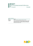
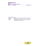
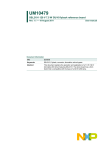
UM10436
UBA3070 230 V and 120 V retrofit LED driver reference design
Rev. 2 — 19 January 2011
User manual
Document information
Info
Content
Keywords
UBA3070, switch-mode current source, non-isolated AC/DC LED driver
Abstract
The NXP Semiconductors UBA3070 retrofit LED driver reference design
implements a single channel 350 mA LED driver. There are two versions
of the reference design. Both use the same PCB, however the population
of the PCBs is slightly different. One board is optimized for operation at
230 V (AC) 50 Hz mains voltage and the other board is optimized for
120 V (AC) 60 Hz. Both options provide an output power of approximately
8 W into a string of LEDs (typically 8 white LEDs). The primary objective of
this board is to achieve high efficiency in combination with a Power Factor
(PF) and ElectroMagnetic Interference (EMI) behavior that are fully
compliant with current regulations. This user manual describes the
UBA3070 retrofit LED driver reference design board version 1.00.
For details on the UBA3070 device refer to the UBA3070 data sheet and
for general application information refer to UBA3070 application note
AN10894.
UM10436
NXP Semiconductors
UBA3070 230 V and 120 V retrofit LED driver reference design
Revision history
Rev
Date
Description
v.2
20110119
second draft
v.1
20110113
first draft
Contact information
For more information, please visit: http://www.nxp.com
For sales office addresses, please send an email to: [email protected]
UM10436
User manual
All information provided in this document is subject to legal disclaimers.
Rev. 2 — 19 January 2011
© NXP B.V. 2011. All rights reserved.
2 of 33
UM10436
NXP Semiconductors
UBA3070 230 V and 120 V retrofit LED driver reference design
1. Introduction
The NXP Semiconductors UBA3070 retrofit LED driver reference design board is
intended to implement a reference design for a UBA3070 based AC/DC LED driver
intended for application in E27-type (and similar type) retrofit light sources. There are two
versions of the board, one is intended to operate at 230 V and the other is intended to
operate at 120 V. The boards demonstrate high energy conversion efficiency and are fully
compliant with existing PF and ElectroMagnetic Compatibility (EMC) regulations.
The circuit implements a single channel Boundary Conduction Mode (BCM) buck
converter and an AC/DC Graetz bridge rectifier input stage combined with a Spangler
circuit.
WARNING
Lethal voltage and fire ignition hazard
The non-insulated high voltages that are present when operating this product, constitute a
risk of electric shock, personal injury, death and/or ignition of fire.
This product is intended for evaluation purposes only. It shall be operated in a designated test
area by personnel qualified according to local requirements and labor laws to work with
non-insulated mains voltages and high-voltage circuits. This product shall never be operated
unattended.
2. Safety warning
This reference board is connected to a high AC voltage (up to 265 V). Touching the demo
board during operation must be avoided at all times. An isolated housing is obligatory
when used in uncontrolled, non laboratory environments. Galvanic isolation of the mains
phase using a fixed or variable transformer (Variac) is always recommended. These
devices can be recognized by the symbols shown in Figure 1
019aab173
a. Isolated
Fig 1.
019aab174
b. Not isolated
Variac isolation symbols
3. Features
Key reference board features include:
• Boundary conduction buck converter operates as a true switch-mode current source
• Designed to operate with an input voltage of 230 V, 50 Hz, ±20 % or 120 V, 60 Hz,
±20 %
• Optimized for an output power of between 6 and 10 W (typically 6 to 10 white LEDs)
at 350 mA output current
UM10436
User manual
All information provided in this document is subject to legal disclaimers.
Rev. 2 — 19 January 2011
© NXP B.V. 2011. All rights reserved.
3 of 33
UM10436
NXP Semiconductors
UBA3070 230 V and 120 V retrofit LED driver reference design
• No custom-made magnetic components required
• Intrinsically protected against short-circuit
• Open LED string OverVoltage Protection (OVP) (outside the main circular board
shape) facilitates experimentation with the reference board
• Built-in OverTemperature Protection (OTP)
• Small shallow form factor and circular PCB for assembly in a traditional Edison-type
(or similar type) light source.
4. Technical specification
The UBA3070 retrofit LED driver reference board implements a 350 mA switch-mode
current source. The board is intended to drive 6 W to 10 W into a string of 6 to 10 white
series LEDs with an intended input voltage of 230 V or 120 V depending on the version of
the board. The LED driver is optimized to supply between 6 W to 10 W to an LED string
load, although it can be used for loads outside this range. However, it may be necessary
to re-dimension several elements of the circuit. For additional information refer to Ref. 1
“AN10894” and Ref. 2 “UBA3070”.
Table 1.
Main characteristics of the UBA3070 230 V retrofit LED driver reference design
Parameter
Value
Remark
Output current
350 mA
±10 %
Supply voltage
230 V (AC)
±20 %
Efficiency
> 86 %
at 8 W load
Power factor
> 0.76
at 8 W load
Drive capability
4 W to 25 W
4 to 25 (white) series LEDs. Design is
optimized for between 6 W to 10 W.
Table 2.
Main characteristics of the UBA3070 120 V retrofit LED driver reference design
Parameter
Value
Remark
Output current
350 mA
±10 %
Supply voltage
120 V (AC)
±20 %
Efficiency
> 86 %
at 8 W load
Power factor
> 0.86
at 8 W load
Drive capability
4 W to 15 W
4 to 15 (white) series LEDs. Design is
optimized for between 6 W to 10 W.
5. Performance data
5.1 Output current
The output current of the LED driver board is primarily determined by the value of the
current sense resistor (parallel resistors R9 and R10). However, the output current is also
slightly dependent on the supply voltage and on the output voltage required by the LED
string load. Figure 2 shows the supply voltage dependence at a typical load of 8 W (8
white series LEDs) for the 230 V reference board and Figure 3 for the 120 V version.
Figure 4 shows how the output current depends on the load voltage (the length of the LED
string) for the 230 V version and Figure 5 shows the dependency for the 120 V version.
UM10436
User manual
All information provided in this document is subject to legal disclaimers.
Rev. 2 — 19 January 2011
© NXP B.V. 2011. All rights reserved.
4 of 33
UM10436
NXP Semiconductors
UBA3070 230 V and 120 V retrofit LED driver reference design
019aab175
400
Io
(mA)
300
200
100
0
100
140
180
220
260
300
V (V)
Fig 2.
Iout dependency as a function of AC supply voltage at 8 W output (230 V)
019aab176
400
Io
(mA)
300
200
100
0
70
90
110
130
150
170
V (V)
Fig 3.
UM10436
User manual
Iout dependency as a function of AC supply voltage at 8 W output (120 V)
All information provided in this document is subject to legal disclaimers.
Rev. 2 — 19 January 2011
© NXP B.V. 2011. All rights reserved.
5 of 33
UM10436
NXP Semiconductors
UBA3070 230 V and 120 V retrofit LED driver reference design
019aab177
400
Io
(mA)
300
200
100
0
10
Fig 4.
20
30
40
50
60
70
V (V)
80
Iout dependency as a function of LED load voltage (230 V)
019aab178
400
Io
(mA)
300
200
100
0
10
Fig 5.
20
30
40
50
60
70
V (V)
80
Iout dependency as a function of LED load voltage (120 V)
5.2 Efficiency
The UBA3070 retrofit LED driver reference board is based upon the principle of a
boundary conduction buck mode power converter. As in other buck mode power
converters the efficiency of such a converter is strongly dependent on the
down-conversion ratio of the converter. At a high output voltage the efficiency is higher
than at a low output voltage. Considering that the output current is near-constant, it can be
concluded that the efficiency of the converter increases with higher output power. Figure 6
shows the efficiency of the LED driver board as a function of the output power (number of
LEDs in series) for the 230 V version and Figure 7 for the 120 V version.
UM10436
User manual
All information provided in this document is subject to legal disclaimers.
Rev. 2 — 19 January 2011
© NXP B.V. 2011. All rights reserved.
6 of 33
UM10436
NXP Semiconductors
UBA3070 230 V and 120 V retrofit LED driver reference design
019aab179
100
η
(%)
95
90
(1)
(2)
(3)
85
80
75
0
5
10
15
20
25
Po (W)
(1) 184 V (AC) input voltage
(2) 230 V (AC) input voltage
(3) 276 V (AC) input voltage
Fig 6.
Typical efficiency of the LED driver board as a function of output power (230 V)
019aab180
100
η
(%)
95
(3)
90
(2)
(1)
85
80
75
0
5
10
15
20
25
Po (W)
(1) 96 V (AC) input voltage
(2) 120 V (AC) input voltage
(3) 144 V (AC) input voltage
Fig 7.
UM10436
User manual
Typical efficiency of the LED driver board as a function of output power (120 V)
All information provided in this document is subject to legal disclaimers.
Rev. 2 — 19 January 2011
© NXP B.V. 2011. All rights reserved.
7 of 33
UM10436
NXP Semiconductors
UBA3070 230 V and 120 V retrofit LED driver reference design
5.3 Power factor
The PF of the UBA3070 retrofit LED driver reference board is enhanced by the use of a
Spangler, or valley-fill, circuit. The PF varies with both the load voltage and the supply
voltage of the board. Figure 8 shows the PF as a function of the output power of the LED
driver board at various supply voltages for the 230 V version and Figure 9 for the 120 V
version.
019aab181
1.0
PF
0.9
(1)
0.8
(2)
0.7
(3)
0.6
0.5
0
5
10
15
20
25
Po (W)
(1) 184 V (AC) input voltage
(2) 230 V (AC) input voltage
(3) 276 V (AC) input voltage
Fig 8.
PF as a function of output power (number of LEDs) for the 230 V version
019aab182
1.0
PF
0.9
(1)
0.8
(2)
(3)
0.7
0.6
0.5
0
5
10
15
20
25
Po (W)
(1) 96 V (AC) input voltage
(2) 120 V (AC) input voltage
(3) 144 V (AC) input voltage
Fig 9.
UM10436
User manual
PF as a function of output power (number of LEDs) for the 120 V version
All information provided in this document is subject to legal disclaimers.
Rev. 2 — 19 January 2011
© NXP B.V. 2011. All rights reserved.
8 of 33
UM10436
NXP Semiconductors
UBA3070 230 V and 120 V retrofit LED driver reference design
5.4 ElectroMagnetic Interference (EMI) compliance
Both versions of the UBA3070 retrofit reference board (230 V and 120 V) are fully EMC
compliant. EMC graphs for both versions are shown in Figure 10 to Figure 15.
019aab167
Fig 10. EMI spectrum at 6 W output power (230 V)
UM10436
User manual
All information provided in this document is subject to legal disclaimers.
Rev. 2 — 19 January 2011
© NXP B.V. 2011. All rights reserved.
9 of 33
UM10436
NXP Semiconductors
UBA3070 230 V and 120 V retrofit LED driver reference design
019aab168
Fig 11. EMI spectrum at 8 W output power (230 V)
UM10436
User manual
All information provided in this document is subject to legal disclaimers.
Rev. 2 — 19 January 2011
© NXP B.V. 2011. All rights reserved.
10 of 33
UM10436
NXP Semiconductors
UBA3070 230 V and 120 V retrofit LED driver reference design
019aab169
Fig 12. EMI spectrum at 10 W output power (230 V)
UM10436
User manual
All information provided in this document is subject to legal disclaimers.
Rev. 2 — 19 January 2011
© NXP B.V. 2011. All rights reserved.
11 of 33
UM10436
NXP Semiconductors
UBA3070 230 V and 120 V retrofit LED driver reference design
019aab164
Fig 13. EMI spectrum at 6 W output power (120 V)
UM10436
User manual
All information provided in this document is subject to legal disclaimers.
Rev. 2 — 19 January 2011
© NXP B.V. 2011. All rights reserved.
12 of 33
UM10436
NXP Semiconductors
UBA3070 230 V and 120 V retrofit LED driver reference design
019aab165
Fig 14. EMI spectrum at 8 W output power (120 V)
UM10436
User manual
All information provided in this document is subject to legal disclaimers.
Rev. 2 — 19 January 2011
© NXP B.V. 2011. All rights reserved.
13 of 33
UM10436
NXP Semiconductors
UBA3070 230 V and 120 V retrofit LED driver reference design
019aab166
Fig 15. EMI spectrum at 10 W output power (120 V)
6. Reference board connectivity
The actual reference design is the part of the circuit that is located inside the circular
shape of the credit-card sized experimentation board. Connections to that part of the
circuit are shown in Figure 16. For experimentation purposes these connections are also
made available on the J3 and J4 screw terminal connectors (see Figure 17). Outside the
circular shape an additional circuit is available that may prove to be useful during
experimentation. This additional circuit is discussed in Section 7.5.
UM10436
User manual
All information provided in this document is subject to legal disclaimers.
Rev. 2 — 19 January 2011
© NXP B.V. 2011. All rights reserved.
14 of 33
UM10436
NXP Semiconductors
UBA3070 230 V and 120 V retrofit LED driver reference design
Cathode
Neutral
Anode
Live
019aab183
Fig 16. UBA3070 retrofit reference board main connections
UM10436
User manual
All information provided in this document is subject to legal disclaimers.
Rev. 2 — 19 January 2011
© NXP B.V. 2011. All rights reserved.
15 of 33
UM10436
NXP Semiconductors
UBA3070 230 V and 120 V retrofit LED driver reference design
Live 230 V
Neutral
Live 120 V
Cathode
Anode
019aab184
Fig 17. UBA3070 retrofit reference board alternative connections for experimentation
7. Circuit description
The circuit on the UBA3070 retrofit LED driver reference board consists of an input and
filtering section, a switching section, a current measurement and feedback section and an
output section. Outside the circular shape an open LED string OVP section is
implemented. The circuit diagram of the reference board is shown in Figure 19. Figure 20
shows the diagram including the open LED string OVP option that is located outside the
main circular area. The Bill of Materials (BOM) for the 230 V version is given in Table 3
and Table 4 for the 120 V version.
7.1 Input and filtering section
The input and filtering section consists of a Greatz diode bridge followed by a Spangler
valley fill circuit. Filtering and EMI suppression is achieved by the filter consisting of C1,
L1 and C4 and by inductor L3 and capacitor C11. The Spangler circuit C2, C3, D1, D2 and
D3 significantly improves the PF of the reference board. Capacitors C2 and C3 are
charged in series and discharged in parallel. This results in a larger phase angle where
energy is consumed from the mains utility infrastructure, and that leads to a higher PF.
UM10436
User manual
All information provided in this document is subject to legal disclaimers.
Rev. 2 — 19 January 2011
© NXP B.V. 2011. All rights reserved.
16 of 33
UM10436
NXP Semiconductors
UBA3070 230 V and 120 V retrofit LED driver reference design
7.2 Switching section
The switching section consists of IC1, (UBA3070) combined with the power components
Q2, D8, L2, R9 and R10. When the UBA3070 switches MOSFET Q2 on, the current in L2
ramps up, and when UBA3070 switches Q2 off, the L2 current continues to flow through
D8 and ramps down. The parallel resistor circuit of R9 and R10 is a current sense resistor
that is in the high current path, see Section 7.3 for further details.
7.3 Current measurement and feedback section
The operation of the UBA3070 boundary mode buck converter relies on the measurement
of two current levels:
• The detection of the peak inductor current level while MOSFET Q2 is on (primary
stroke)
• The detection of zero inductor current while MOSFET Q2 is off and the current is
flowing through D8 (secondary stroke)
Due to the current ramping up and ramping down with a constant slope, and there being
no dead-time between two subsequent cycles, the average current that is supplied by the
switching section is exactly half the inductor peak current.
7.3.1 Peak current detection
The peak inductor current is detected by measuring the voltage drop across R9 and R10.
This voltage drop is applied to the UBA3070 SENSE pin, and the UBA3070 reacts to the
detection of the peak current by switching off MOSFET Q2. The peak voltage level
(across R9 and R10) at which the detection of the peak current occurs is typically 0.52 V.
See Ref. 1 “AN10894” for more details.
7.3.2 Demag detection
Zero inductor current is detected by the indirect demag detection strategy. Indirect demag
detection relies on the phenomenon that a ringing voltage (caused by resonance between
inductor L2 and the (parasitic) capacitance CDS of Q2) appears at the DRAIN node of
MOSFET Q2 when the secondary stroke has finished. The resonating waveform
propagates through capacitor C8 and resistor R8 to the R7, R6, C7, D9a/b network and to
the UBA3070 MASK pin. The first valley of the ringing signal causes the MASK pin
voltage to drop below 100 mV and is therefore an indirect way of detecting
demagnetization of the L2 inductor.
7.4 Output section
The switching section produces a current waveform in the inductor that looks like a
sawtooth; current ramps-up linearly from 0 to Ipeak and then ramps down linearly from Ipeak
to 0. In most circumstances this type of current waveform must not be applied to an LED
string. For that reason, capacitor C9 is used in the output section to reduce the ripple on
the LED current. Details about the dimensioning of the ripple filter can be found in Ref. 1
“AN10894”. The LED string is connected to connectors J2.2 (anode of the LED string) and
J2.1 (cathode of the LED string).
UM10436
User manual
All information provided in this document is subject to legal disclaimers.
Rev. 2 — 19 January 2011
© NXP B.V. 2011. All rights reserved.
17 of 33
UM10436
NXP Semiconductors
UBA3070 230 V and 120 V retrofit LED driver reference design
7.5 Open LED string OVP
The open LED string OVP section is not a part of the actual reference design. The circuit
is added to the credit card sized board outside the main circular shape. It is intended to be
used only during experimentation. With Zener diode D11 the maximum output voltage of
the LED driver is set; in the default implementation this voltage is set to approximately
75 V.
In case of an open LED string, the output voltage of the LED driver would rise to
approximately the rectified mains voltage (for a 230 V mains voltage that would be
approximately 325 V (DC)). If the voltage rating of output capacitor C9 is 325 V (DC) or
above, there would technically be no objection against this. However, a 400 V C9
capacitor is much bigger and much more expensive than a 100 V capacitor. Normally 100
V is a sufficient voltage rating when the application is used with LED strings up to a length
of 25 in series LEDs.
For that reason a small 100 V C9 capacitor was mounted on the reference board by
default. In order to cover for wiring mistakes during experimentation the open LED string
OVP circuit was added outside the circular shape. The feature can be disabled by cutting
the jumper wire between J5 and J6. However, care must be taken that the voltage rating
of the C9 capacitor is not exceeded.
8. Circuit variations and extensions
8.1 Overtemperature output current reduction
Protection against overheating can be implemented by mounting a Negative Temperature
Coefficient (NTC) resistor in the R4 position. The resistive divider R4 and R5 must be
dimensioned so that the voltage applied to the PWM pin of the UBA3070 IC starts to
exceed the 1.0 V level when the temperature rises above a selected critical temperature.
This results in a reduction of the peak current in the LED string and thus in a reduction of
the average LED current and the associated heat generation.
The operation of this mechanism is as follows. The magnitude of the peak current that
flows through the L2 inductor can be controlled by feeding an analog voltage signal to the
UBA3070 PWM pin. When the CTRL level rises above 1.0 V (typically) the sense voltage
(measured across R9 and R10) that triggers peak current detection is reduced. Figure 18
shows how the sense level depends on the PWM pin control voltage.
UM10436
User manual
All information provided in this document is subject to legal disclaimers.
Rev. 2 — 19 January 2011
© NXP B.V. 2011. All rights reserved.
18 of 33
UM10436
NXP Semiconductors
UBA3070 230 V and 120 V retrofit LED driver reference design
Vsense(max)
(V)
0.52
1
(typ)
1.5
(typ)
VCTRL (V)
019aab170
Fig 18. Sense level and output current dependence as a function of control voltage
8.2 Output current level
The output current level of the UBA3070 retrofit reference board can be adapted by
changing the value of the current sense resistors (R9 and R10). Other components in the
switching section (see Section 7.2) may also need adaptation. Details regarding
re-dimensioning are given in Ref. 1 “AN10894”. Apart from re-dimensioning the switching
section it may be necessary to adapt components in the input and filtering section in order
to meet PF and EMI requirements.
8.3 Higher output voltage
By default the UBA3070 retrofit LED driver reference board supports a maximum output
voltage of up to 100 V (determined by the voltage rating of the C9 capacitor). With the
open LED string OVP enabled this voltage is reduced to 75 V. In the default
implementation the reference board is optimized for an output voltage ranging from 20 V
to 30 V. A higher output voltage can be supported if the voltage rating of the C9 capacitor
is changed. In most circumstances it is also necessary to also change the dimensioning of
the input and filtering section components in order to be compliant with PF and EMI
regulations.
8.4 Combining circuit variation and extensions
The circuit variations and extensions detailed above can be combined. It is the
responsibility of the user to correctly dimension the circuit and the components.
Assistance is available from NXP Semiconductors application support if needed.
UM10436
User manual
All information provided in this document is subject to legal disclaimers.
Rev. 2 — 19 January 2011
© NXP B.V. 2011. All rights reserved.
19 of 33
xxxx xxxxxxxxxxxxxxxxxxxxxxxxxxxxxx x xxxxxxxxxxxxxx xxxxxxxxxx xxx xxxxxx xxxxxxxxxxxxxxxxxxxxxxx xxxxxxxxxxxxxxxxxxxxxx
xxxxx xxxxxx xx xxxxxxxxxxxxxxxxxxxxxxxxxxxxx xxxxxxxxxxxxxxxxxxxxxx xxxxxxxxxxx xxxxxxx xxxxxxxxxxxxxxxxxxx
xxxxxxxxxxxxxxxx xxxxxxxxxxxxxx xxxxxx xx xxxxxxxxxxxxxxxxxxxxxxxxxxxxxxxx xxxxxxxxxxxxxxxxxxxxxxxx xxxxxxx
xxxxxxxxxxxxxxxxxxxxxxxxxxxxxxxxxxxxxxxxxxxxxx xxxxxxxxxxx xxxxx x x
NXP Semiconductors
9. Circuit diagrams
UM10436
User manual
L1
J2.2
C9
C2
J2.1
D8
D7b
D3
BR1
L2
R3
F1
D7a
J1.2
C6
D2
C11
L3
C1
C4
D5
J1.1
VCC
DRAIN
MASK
R6
C5
C5
R4
C8
R8
IC1
Q1
R7
D9a
D9b
Q2
UBA3070
GATE
D1
C3
D4
PWN
SENSE
D6
R5
GND
R9
R10
019aab171
UM10436
20 of 33
© NXP B.V. 2011. All rights reserved.
Fig 19. UBA3070 retrofit LED driver reference board (inside circular shape)
UBA3070 230 V and 120 V retrofit LED driver reference design
Rev. 2 — 19 January 2011
All information provided in this document is subject to legal disclaimers.
R2
xxxx xxxxxxxxxxxxxxxxxxxxxxxxxxxxxx x xxxxxxxxxxxxxx xxxxxxxxxx xxx xxxxxx xxxxxxxxxxxxxxxxxxxxxxx xxxxxxxxxxxxxxxxxxxxxx
xxxxx xxxxxx xx xxxxxxxxxxxxxxxxxxxxxxxxxxxxx xxxxxxxxxxxxxxxxxxxxxx xxxxxxxxxxx xxxxxxx xxxxxxxxxxxxxxxxxxx
xxxxxxxxxxxxxxxx xxxxxxxxxxxxxx xxxxxx xx xxxxxxxxxxxxxxxxxxxxxxxxxxxxxxxx xxxxxxxxxxxxxxxxxxxxxxxx xxxxxxx
xxxxxxxxxxxxxxxxxxxxxxxxxxxxxxxxxxxxxxxxxxxxxx xxxxxxxxxxx xxxxx x x
NXP Semiconductors
UM10436
User manual
L1
J2.2
J4.1
J2.1
J4.2
C9
R2
C2
D8
D7b
D3
BR1
L2
R3
F1
D7a
J1.2
C6
D2
C11
L3
C1
C4
D5
VCC
J1.1
DRAIN
MASK
R4
D10
R6
R12
C5
J3.1
C5
C8
R8
IC1
Q1
R7
D9a
D9b
Q2
UBA3070
J3.3
R13
GATE
D1
C3
D4
PWN
D11
SENSE
D6
R5
IC2
GND
R9
J5 J6
R10
C10
R11
019aab172
UM10436
21 of 33
© NXP B.V. 2011. All rights reserved.
Fig 20. UBA3070 retrofit LED driver reference board (full experimental board)
UBA3070 230 V and 120 V retrofit LED driver reference design
Rev. 2 — 19 January 2011
All information provided in this document is subject to legal disclaimers.
J3.2
UM10436
NXP Semiconductors
UBA3070 230 V and 120 V retrofit LED driver reference design
10. Bill of Materials (BOM)
Table 3 provides detailed component information for the 230 V default reference design
and Table 4 for the 120 V version.
Table 3.
UM10436
User manual
BOM for the 230 V retrofit LED driver reference design
Reference
Component
Package
Remarks
IC1
NXP Semiconductors UBA3070
SO8
-
IC2[1]
Vishay SFH615A
DIP4
-
Q1
NXP Semiconductors PBHV8540T
SOT23
-
Q2
ST STD5NK50Z-1
IPAK
-
BR1
Fairchild MB6S
TO-269AA
-
D1
1N4007
DO-41
-
D2
1N4007
DO-41
-
D3
1N4007
DO-41
-
D4
NXP Semiconductors BZX384-C15
SOD323
-
D5
NXP Semiconductors BAS316
SOD323
-
D6
NXP Semiconductors BZX384-C15
SOD323
-
D7
NXP Semiconductors BAV99
SOT23
-
D8
Vishay BYG20J
DO-214AC (SMA)
-
D9
NXP Semiconductors BAV99
SOT23
-
D10[1]
NXP Semiconductors BAS321
SOD323
-
D11[1]
NXP Semiconductors BZX384-C75
SOD323
-
C1
150 nF, 400 V
through-hole
-
C2
10 μF, 200 V
through-hole 2E
-
C3
10 μF, 200 V
through-hole 2E
-
C4
150 nF, 400 V
through-hole
-
C5
680 nF, 25 V
0805
-
C6
100 pF, 400 V
1206
-
C7
47 pF, 25 V
0603
-
C8
100 pF, 400 V
1206
-
C9
470 nF, 100 V
through-hole 2E
-
C10[1]
47 nF, 100 V
1206
-
C11
150 nF, 275 V
through-hole
-
F1
fuse 1 A slow blow
through-hole
-
L1
4.7 mH, 80 mA
through-hole
e.g. Murata 22R475C
L2
470 μH, 700 mA
through-hole 2E
e.g. Panasonic
ELC10D471E
L3
4.7 mH, 80 mA
through-hole
e.g. Murata 22R475C
R1
-
-
not present
R2
10 MΩ
1206
-
R3
10 MΩ
1206
-
R4
not mounted
0805
-
R5
10 kΩ
0805
-
All information provided in this document is subject to legal disclaimers.
Rev. 2 — 19 January 2011
© NXP B.V. 2011. All rights reserved.
22 of 33
UM10436
NXP Semiconductors
UBA3070 230 V and 120 V retrofit LED driver reference design
Table 3.
Reference
Component
Package
Remarks
R6
22 kΩ
0603
-
R7
2.4 kΩ
0603
-
R8
150 kΩ
1206
-
R9
1.5 Ω, 0.25 W
1206
-
R10
1.8 Ω, 0.25 W
1206
-
R11[1]
22 kΩ
0603
-
R12[1]
22 Ω
1206
-
R13[1]
2.2 kΩ
1206
-
J1
connector
-
wire mounting holes in
PCB
J2
connector
-
wire mounting holes in
PCB
J3[1]
Phoenix 2 terminal connector
2E pitch
Phoenix part number
1711725
J4[1]
Phoenix 2 terminal connector
2E pitch
Phoenix part number
1711725
[1]
Outside the main circular shape and not part of the actual reference design.
Table 4.
UM10436
User manual
BOM for the 230 V retrofit LED driver reference design …continued
BOM for the 120 V retrofit LED driver reference design
Reference
Component
Package
Remarks
IC1
NXP Semiconductors UBA3070
SO8
-
IC2[1]
Vishay SFH615A
DIP4
-
Q1
NXP Semiconductors
PBHV8540T
SOT23
-
Q2
ST STD5NK50Z-1
IPAK
-
BR1
Fairchild MB6S
TO-269AA
-
D1
1N4007
DO-41
-
D2
1N4007
DO-41
-
D3
1N4007
DO-41
-
D4
NXP Semiconductors
BZX384-C15
SOD323
-
D5
NXP Semiconductors BAS316
SOD323
-
D6
NXP Semiconductors
BZX384-C15
SOD323
-
D7
NXP Semiconductors BAV99
SOT23
-
D8
Vishay BYG20J
DO-214AC (SMA)
-
D9
NXP Semiconductors BAV99
SOT23
-
D10[1]
NXP Semiconductors BAS321
SOD323
-
D11[1]
NXP Semiconductors
BZX384-C75
SOD323
-
C1
150 nF, 400 V
through-hole
-
C2
22 μF, 100 V
through-hole 2E
-
C3
22 μF, 100 V
through-hole 2E
-
All information provided in this document is subject to legal disclaimers.
Rev. 2 — 19 January 2011
© NXP B.V. 2011. All rights reserved.
23 of 33
UM10436
NXP Semiconductors
UBA3070 230 V and 120 V retrofit LED driver reference design
Table 4.
BOM for the 120 V retrofit LED driver reference design …continued
Reference
Component
Package
Remarks
C4
150 nF, 200 V
through-hole
-
C5
680 nF, 25 V
0805
-
C6
220 pF, 200 V
1206
-
C7
47 pF, 25 V
0603
-
C8
220 pF, 200 V
1206
-
C9
470 nF, 100 V
through-hole 2E
-
C10[1]
47 nF, 100 V
1206
-
C11
150 nF, 150 V
through-hole
-
F1
fuse 1 A slow blow
through-hole
-
L1
4.7 mH, 80 mA
through-hole
e.g. Murata 22R475C
L2
470 μH, 700 mA
through-hole 2E
e.g. Panasonic
ELC10D471E
L3
4.7 mH, 80 mA
through-hole
e.g. Murata 22R475C
R1
-
-
not present
R2
4.7 MΩ
1206
-
R3
4.7 MΩ
1206
-
R4
not mounted
0805
-
R5
10 kΩ
0805
-
R6
22 kΩ
0603
-
R7
2.4 kΩ
0603
-
R8
75 kΩ
1206
-
R9
1.5 Ω, 0.25 W
1206
-
R10
1.5 Ω, 0.25 W
1206
-
R11[1]
22 kΩ
0603
-
R12[1]
22 Ω
1206
-
R13[1]
2.2 kΩ
1206
-
J1
connector
-
wire mounting holes in PCB
J2
connector
-
wire mounting holes in PCB
J3[1]
Phoenix 2 terminal connector
2E pitch
Phoenix part number
1711725
J4[1]
Phoenix 2 terminal connector
2E pitch
Phoenix part number
1711725
[1]
Outside the main circular shape and not part of the actual reference design.
11. Printed-Circuit Board (PCB)
The UBA3070 retrofit LED driver reference board is located in the circular shape of the
credit card sized experimentation board. The dimensions of the full experimentation board
are approximately 85 x 54 mm and the diameter of the circular board is 40 mm. The demo
board is produced on 1.6 mm FR4 with single-sided 1 oz. copper (35 μm). It is also
possible to use FR2 as the PCB material. A top view of the PCB is shown in Figure 21.
UM10436
User manual
All information provided in this document is subject to legal disclaimers.
Rev. 2 — 19 January 2011
© NXP B.V. 2011. All rights reserved.
24 of 33
UM10436
NXP Semiconductors
UBA3070 230 V and 120 V retrofit LED driver reference design
The full PCB accommodates the circuit as shown in Figure 20. The circular shape
contains the circuit as shown in Figure 19.
019aab185
Fig 21. PCB
The Gerber file set for the production of the PCBs is available from NXP Semiconductors
as shown in Figure 22 to Figure 24.
UM10436
User manual
All information provided in this document is subject to legal disclaimers.
Rev. 2 — 19 January 2011
© NXP B.V. 2011. All rights reserved.
25 of 33
UM10436
NXP Semiconductors
UBA3070 230 V and 120 V retrofit LED driver reference design
019aab186
Fig 22. Top silk screen (Top view)
UM10436
User manual
All information provided in this document is subject to legal disclaimers.
Rev. 2 — 19 January 2011
© NXP B.V. 2011. All rights reserved.
26 of 33
UM10436
NXP Semiconductors
UBA3070 230 V and 120 V retrofit LED driver reference design
019aab187
Fig 23. Bottom silk screen (Bottom view)
UM10436
User manual
All information provided in this document is subject to legal disclaimers.
Rev. 2 — 19 January 2011
© NXP B.V. 2011. All rights reserved.
27 of 33
UM10436
NXP Semiconductors
UBA3070 230 V and 120 V retrofit LED driver reference design
019aab188
Fig 24. Bottom copper (Bottom view)
UM10436
User manual
All information provided in this document is subject to legal disclaimers.
Rev. 2 — 19 January 2011
© NXP B.V. 2011. All rights reserved.
28 of 33
UM10436
NXP Semiconductors
UBA3070 230 V and 120 V retrofit LED driver reference design
12. Abbreviations
Table 5.
Abbreviations
Acronym
Description
EMC
ElectroMagnetic Compatibility
EMI
ElectroMagnetic Interference
MOSFET
Metal-Oxide Semiconductor Field-Effect Transistor
NTC
Negative Temperature Coefficient
OTP
OverTemperature Protection
OVP
OverVoltage Protection
PCB
Printed-Circuit Board
PF
Power Factor
13. References
UM10436
User manual
[1]
AN10894 — Application note: Application aspects of the UBA3070 switch mode
LED driver
[2]
UBA3070 — Data sheet: LED backlight driver IC
All information provided in this document is subject to legal disclaimers.
Rev. 2 — 19 January 2011
© NXP B.V. 2011. All rights reserved.
29 of 33
UM10436
NXP Semiconductors
UBA3070 230 V and 120 V retrofit LED driver reference design
14. Legal information
14.1 Definitions
Draft — The document is a draft version only. The content is still under
internal review and subject to formal approval, which may result in
modifications or additions. NXP Semiconductors does not give any
representations or warranties as to the accuracy or completeness of
information included herein and shall have no liability for the consequences of
use of such information.
14.2 Disclaimers
Limited warranty and liability — Information in this document is believed to
be accurate and reliable. However, NXP Semiconductors does not give any
representations or warranties, expressed or implied, as to the accuracy or
completeness of such information and shall have no liability for the
consequences of use of such information.
In no event shall NXP Semiconductors be liable for any indirect, incidental,
punitive, special or consequential damages (including - without limitation - lost
profits, lost savings, business interruption, costs related to the removal or
replacement of any products or rework charges) whether or not such
damages are based on tort (including negligence), warranty, breach of
contract or any other legal theory.
Notwithstanding any damages that customer might incur for any reason
whatsoever, NXP Semiconductors’ aggregate and cumulative liability towards
customer for the products described herein shall be limited in accordance
with the Terms and conditions of commercial sale of NXP Semiconductors.
Export control — This document as well as the item(s) described herein
may be subject to export control regulations. Export might require a prior
authorization from national authorities.
Evaluation products — This product is provided on an “as is” and “with all
faults” basis for evaluation purposes only. NXP Semiconductors, its affiliates
and their suppliers expressly disclaim all warranties, whether express, implied
or statutory, including but not limited to the implied warranties of
non-infringement, merchantability and fitness for a particular purpose. The
entire risk as to the quality, or arising out of the use or performance, of this
product remains with customer.
In no event shall NXP Semiconductors, its affiliates or their suppliers be liable
to customer for any special, indirect, consequential, punitive or incidental
damages (including without limitation damages for loss of business, business
interruption, loss of use, loss of data or information, and the like) arising out
the use of or inability to use the product, whether or not based on tort
(including negligence), strict liability, breach of contract, breach of warranty or
any other theory, even if advised of the possibility of such damages.
Notwithstanding any damages that customer might incur for any reason
whatsoever (including without limitation, all damages referenced above and
all direct or general damages), the entire liability of NXP Semiconductors, its
affiliates and their suppliers and customer’s exclusive remedy for all of the
foregoing shall be limited to actual damages incurred by customer based on
reasonable reliance up to the greater of the amount actually paid by customer
for the product or five dollars (US$5.00). The foregoing limitations, exclusions
and disclaimers shall apply to the maximum extent permitted by applicable
law, even if any remedy fails of its essential purpose.
Right to make changes — NXP Semiconductors reserves the right to make
changes to information published in this document, including without
limitation specifications and product descriptions, at any time and without
notice. This document supersedes and replaces all information supplied prior
to the publication hereof.
Safety of high-voltage evaluation products — The non-insulated high
voltages that are present when operating this product, constitute a risk of
electric shock, personal injury, death and/or ignition of fire. This product is
intended for evaluation purposes only. It shall be operated in a designated
test area by personnel that is qualified according to local requirements and
labor laws to work with non-insulated mains voltages and high-voltage
circuits.
Suitability for use — NXP Semiconductors products are not designed,
authorized or warranted to be suitable for use in life support, life-critical or
safety-critical systems or equipment, nor in applications where failure or
malfunction of an NXP Semiconductors product can reasonably be expected
to result in personal injury, death or severe property or environmental
damage. NXP Semiconductors accepts no liability for inclusion and/or use of
NXP Semiconductors products in such equipment or applications and
therefore such inclusion and/or use is at the customer’s own risk.
The product does not comply with IEC 60950 based national or regional
safety standards. NXP Semiconductors does not accept any liability for
damages incurred due to inappropriate use of this product or related to
non-insulated high voltages. Any use of this product is at customer’s own risk
and liability. The customer shall fully indemnify and hold harmless NXP
Semiconductors from any liability, damages and claims resulting from the use
of the product.
Applications — Applications that are described herein for any of these
products are for illustrative purposes only. NXP Semiconductors makes no
representation or warranty that such applications will be suitable for the
specified use without further testing or modification.
Customers are responsible for the design and operation of their applications
and products using NXP Semiconductors products, and NXP Semiconductors
accepts no liability for any assistance with applications or customer product
design. It is customer’s sole responsibility to determine whether the NXP
Semiconductors product is suitable and fit for the customer’s applications and
products planned, as well as for the planned application and use of
customer’s third party customer(s). Customers should provide appropriate
design and operating safeguards to minimize the risks associated with their
applications and products.
NXP Semiconductors does not accept any liability related to any default,
damage, costs or problem which is based on any weakness or default in the
customer’s applications or products, or the application or use by customer’s
third party customer(s). Customer is responsible for doing all necessary
testing for the customer’s applications and products using NXP
Semiconductors products in order to avoid a default of the applications and
the products or of the application or use by customer’s third party
customer(s). NXP does not accept any liability in this respect.
UM10436
User manual
Non-automotive qualified products — Unless this data sheet expressly
states that this specific NXP Semiconductors product is automotive qualified,
the product is not suitable for automotive use. It is neither qualified nor tested
in accordance with automotive testing or application requirements. NXP
Semiconductors accepts no liability for inclusion and/or use of
non-automotive qualified products in automotive equipment or applications.
In the event that customer uses the product for design-in and use in
automotive applications to automotive specifications and standards, customer
(a) shall use the product without NXP Semiconductors’ warranty of the
product for such automotive applications, use and specifications, and (b)
whenever customer uses the product for automotive applications beyond
NXP Semiconductors’ specifications such use shall be solely at customer’s
own risk, and (c) customer fully indemnifies NXP Semiconductors for any
liability, damages or failed product claims resulting from customer design and
use of the product for automotive applications beyond NXP Semiconductors’
standard warranty and NXP Semiconductors’ product specifications.
14.3 Trademarks
Notice: All referenced brands, product names, service names and trademarks
are the property of their respective owners.
All information provided in this document is subject to legal disclaimers.
Rev. 2 — 19 January 2011
© NXP B.V. 2011. All rights reserved.
30 of 33
UM10436
NXP Semiconductors
UBA3070 230 V and 120 V retrofit LED driver reference design
15. Tables
Table 1.
Table 2.
Table 3.
Table 4.
Table 5.
Main characteristics of the UBA3070 230 V
retrofit LED driver reference design . . . . . . . . . .4
Main characteristics of the UBA3070 120 V
retrofit LED driver reference design . . . . . . . . . .4
BOM for the 230 V retrofit LED driver
reference design . . . . . . . . . . . . . . . . . . . . . . .22
BOM for the 120 V retrofit LED driver
reference design . . . . . . . . . . . . . . . . . . . . . . .23
Abbreviations . . . . . . . . . . . . . . . . . . . . . . . . . .29
continued >>
UM10436
User manual
All information provided in this document is subject to legal disclaimers.
Rev. 2 — 19 January 2011
© NXP B.V. 2011. All rights reserved.
31 of 33
UM10436
NXP Semiconductors
UBA3070 230 V and 120 V retrofit LED driver reference design
16. Figures
Fig 1.
Fig 2.
Fig 3.
Fig 4.
Fig 5.
Fig 6.
Fig 7.
Fig 8.
Fig 9.
Fig 10.
Fig 11.
Fig 12.
Fig 13.
Fig 14.
Fig 15.
Fig 16.
Fig 17.
Fig 18.
Fig 19.
Fig 20.
Fig 21.
Fig 22.
Fig 23.
Fig 24.
Variac isolation symbols. . . . . . . . . . . . . . . . . . . . .3
Iout dependency as a function of AC supply
voltage at 8 W output (230 V) . . . . . . . . . . . . . . . .5
Iout dependency as a function of AC supply
voltage at 8 W output (120 V) . . . . . . . . . . . . . . . .5
Iout dependency as a function of LED load
voltage (230 V). . . . . . . . . . . . . . . . . . . . . . . . . . . .6
Iout dependency as a function of LED load
voltage (120 V). . . . . . . . . . . . . . . . . . . . . . . . . . . .6
Typical efficiency of the LED driver board as
a function of output power (230 V). . . . . . . . . . . . .7
Typical efficiency of the LED driver board as
a function of output power (120 V). . . . . . . . . . . . .7
PF as a function of output power
(number of LEDs) for the 230 V version . . . . . . . .8
PF as a function of output power
(number of LEDs) for the 120 V version . . . . . . . .8
EMI spectrum at 6 W output power (230 V). . . . . .9
EMI spectrum at 8 W output power (230 V). . . . .10
EMI spectrum at 10 W output power (230 V). . . . 11
EMI spectrum at 6 W output power (120 V). . . . .12
EMI spectrum at 8 W output power (120 V). . . . .13
EMI spectrum at 10 W output power (120 V). . . .14
UBA3070 retrofit reference board main
connections . . . . . . . . . . . . . . . . . . . . . . . . . . . . .15
UBA3070 retrofit reference board alternative
connections for experimentation . . . . . . . . . . . . .16
Sense level and output current dependence
as a function of control voltage . . . . . . . . . . . . . .19
UBA3070 retrofit LED driver reference board
(inside circular shape) . . . . . . . . . . . . . . . . . . . . .20
UBA3070 retrofit LED driver reference board
(full experimental board) . . . . . . . . . . . . . . . . . . .21
PCB . . . . . . . . . . . . . . . . . . . . . . . . . . . . . . . . . . .25
Top silk screen (Top view) . . . . . . . . . . . . . . . . . .26
Bottom silk screen (Bottom view). . . . . . . . . . . . .27
Bottom copper (Bottom view). . . . . . . . . . . . . . . .28
continued >>
UM10436
User manual
All information provided in this document is subject to legal disclaimers.
Rev. 2 — 19 January 2011
© NXP B.V. 2011. All rights reserved.
32 of 33
UM10436
NXP Semiconductors
UBA3070 230 V and 120 V retrofit LED driver reference design
17. Contents
1
2
3
4
5
5.1
5.2
5.3
5.4
6
7
7.1
7.2
7.3
7.3.1
7.3.2
7.4
7.5
8
8.1
8.2
8.3
8.4
9
10
11
12
13
14
14.1
14.2
14.3
15
16
17
Introduction . . . . . . . . . . . . . . . . . . . . . . . . . . . . 3
Safety warning . . . . . . . . . . . . . . . . . . . . . . . . . . 3
Features . . . . . . . . . . . . . . . . . . . . . . . . . . . . . . . 3
Technical specification . . . . . . . . . . . . . . . . . . . 4
Performance data. . . . . . . . . . . . . . . . . . . . . . . . 4
Output current. . . . . . . . . . . . . . . . . . . . . . . . . . 4
Efficiency . . . . . . . . . . . . . . . . . . . . . . . . . . . . . 6
Power factor . . . . . . . . . . . . . . . . . . . . . . . . . . . 8
ElectroMagnetic Interference (EMI)
compliance . . . . . . . . . . . . . . . . . . . . . . . . . . . . 9
Reference board connectivity. . . . . . . . . . . . . 14
Circuit description . . . . . . . . . . . . . . . . . . . . . . 16
Input and filtering section . . . . . . . . . . . . . . . . 16
Switching section . . . . . . . . . . . . . . . . . . . . . . 17
Current measurement and feedback section . 17
Peak current detection . . . . . . . . . . . . . . . . . . 17
Demag detection . . . . . . . . . . . . . . . . . . . . . . 17
Output section . . . . . . . . . . . . . . . . . . . . . . . . 17
Open LED string OVP . . . . . . . . . . . . . . . . . . 18
Circuit variations and extensions . . . . . . . . . 18
Overtemperature output current reduction . . . 18
Output current level . . . . . . . . . . . . . . . . . . . . 19
Higher output voltage . . . . . . . . . . . . . . . . . . . 19
Combining circuit variation and extensions . . 19
Circuit diagrams . . . . . . . . . . . . . . . . . . . . . . . 20
Bill of Materials (BOM). . . . . . . . . . . . . . . . . . . 22
Printed-Circuit Board (PCB) . . . . . . . . . . . . . . 24
Abbreviations . . . . . . . . . . . . . . . . . . . . . . . . . . 29
References . . . . . . . . . . . . . . . . . . . . . . . . . . . . 29
Legal information. . . . . . . . . . . . . . . . . . . . . . . 30
Definitions . . . . . . . . . . . . . . . . . . . . . . . . . . . . 30
Disclaimers . . . . . . . . . . . . . . . . . . . . . . . . . . . 30
Trademarks. . . . . . . . . . . . . . . . . . . . . . . . . . . 30
Tables . . . . . . . . . . . . . . . . . . . . . . . . . . . . . . . . 31
Figures . . . . . . . . . . . . . . . . . . . . . . . . . . . . . . . 32
Contents . . . . . . . . . . . . . . . . . . . . . . . . . . . . . . 33
Please be aware that important notices concerning this document and the product(s)
described herein, have been included in section ‘Legal information’.
© NXP B.V. 2011.
All rights reserved.
For more information, please visit: http://www.nxp.com
For sales office addresses, please send an email to: [email protected]
Date of release: 19 January 2011
Document identifier: UM10436