1
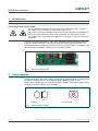
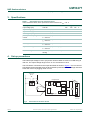
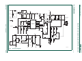
UM10477 SSL2101 120 V (AC) flyback task light 20 V/450 mA driver board Rev. 1 — 23 June 2011 User manual Document information Info Content Keywords SSL2101, LED driver, dimmable, task light, 450 mA LED Abstract This document describes the SSL2101 task light 120 V (AC), dimmable, 450 mA LED driver board. The board is designed to highlight the high performance dimming, wide compatibility, high-efficiency capability by driving various numbers of LEDs. UM10477 NXP Semiconductors SSL2101 120 V (AC) flyback task light 20 V/450 mA driver board Revision history Rev Date Description v.1 20110623 first issue Contact information For more information, please visit: http://www.nxp.com For sales office addresses, please send an email to: [email protected] UM10477 User manual All information provided in this document is subject to legal disclaimers. Rev. 1 — 23 June 2011 © NXP B.V. 2011. All rights reserved. 2 of 10 UM10477 NXP Semiconductors SSL2101 120 V (AC) flyback task light 20 V/450 mA driver board 1. Introduction WARNING Lethal voltage and fire ignition hazard The non-insulated high voltages that are present when operating this product, constitute a risk of electric shock, personal injury, death and/or ignition of fire. This product is intended for evaluation purposes only. It shall be operated in a designated test area by personnel qualified according to local requirements and labor laws to work with non-insulated mains voltages and high-voltage circuits. This product shall never be operated unattended. The SSL2101 task light board is a 120 V (AC), dimmable, 450 mA LED driver board. It employs a flyback converter to drive power LEDs that require galvanic isolation. The board is designed to highlight high performance dimming, wide dimmer compatibility, high efficiency and the capability of driving various numbers of LEDs. 019aac594 Fig 1. SSL2101 task light board 2. Safety warning Connect the board to the mains voltage. Avoid touching the board while it is connected to the mains voltage at all times. An isolated housing is obligatory when used in uncontrolled, non-laboratory environments. Galvanic isolation of the mains phase using a variable transformer is always recommended. 019aab174 019aab173 a. Isolated Fig 2. UM10477 User manual b. Not isolated Variac isolation symbols All information provided in this document is subject to legal disclaimers. Rev. 1 — 23 June 2011 © NXP B.V. 2011. All rights reserved. 3 of 10 UM10477 NXP Semiconductors SSL2101 120 V (AC) flyback task light 20 V/450 mA driver board 3. Specifications Table 1. Specifications for the reference board Unless otherwise stated, these specifications were measured at Tamb = 25 C Description Conditions Min Typ Max Unit input voltage (VIN) at 60 Hz 108 120 132 V 15 - 30 V - 450 - mA 50 60 70 kHz % output voltage (Vo) output current (Io) VIN = 120 V (AC); Vo = 16.4 V switching frequency peak-to-peak output ripple current VIN = 120 V (AC); Vo = 16.4 V; Io = 450 mA - 30 - Power Factor VIN = 120 V (AC); Vo = 16.4 V; Io = 450 mA 0.9 0.95 - efficiency VIN = 120 V (AC); Vo = 16.4 V; Io = 450 mA 77 80 - % output current regulation Line: 106 V (AC) to 135 V (AC); Io = 450 mA - - 6 % isolation voltage between primary and secondary winding - 2.5 - kV 4. Set-up procedures The board input voltage is 120 V (AC) and it can drive either a 5-LED or 9-LED string at 450 mA. The output voltage range is from 15 V to a maximum of 30 V. The LED load is connected to the output terminals as shown in Figure 3. Do not connect LED load to the driver board when the driver board is powered to avoid damage caused to LEDs due to the hot-plugging inrush current. 120 V (AC) 60 Hz task light board A + dimmer + V L A + V T1 - N = 005 A LED LED board 019aac582 Fig 3. UM10477 User manual Connection to the driver board All information provided in this document is subject to legal disclaimers. Rev. 1 — 23 June 2011 © NXP B.V. 2011. All rights reserved. 4 of 10 UM10477 NXP Semiconductors SSL2101 120 V (AC) flyback task light 20 V/450 mA driver board 5. Functional description The SSL2101 IC is used to configure a flyback converter operating at 60 kHz and produces a constant output current (450 mA) to drive up to 9-LEDs. The current corresponds to an output voltage between 15 V and 30 V. When an input voltage is applied to the SSL2101, it is initially powered by the rectified voltage. Once the SSL2101 starts switching, the SSL2101 is then supplied by the inductor’s auxiliary winding to improve efficiency. The flyback converter operates in Discontinuous Conduction Mode (DCM) to minimize the magnetic component and switching losses. In addition, a high Power Factor (PF) is obtained due to the DCM operation. When operating in Boundary Conduction Mode (BCM) at full load, flyback converter efficiency is optimized and enhanced by the valley switching detection. When mains dimmers are used, the circuit detects the rectified voltage change. In addition, the circuit reduces the duty cycle and switching frequency to reduce the output current for deep dimming. To increase the dimmer compatibility without sacrificing efficiency, the board uses a highly efficient, bleeding circuit to ensure flicker-free deep dimming with a wide range of mains dimmers. It detects circuit current and if necessary, supplements bleeding current to meet the required hold currents of triac dimmers. The bleeding circuit ensures the widest dimmer compatibility while keeping heat generation to the minimum. The circuit also includes an active damper to increase the efficiency and limit the inrush current during the phase cutting transient. An ElectroMagnetic interference (EMI) filter is included to ensure compliance with the EMI requirement of EN55015/FCC15. Five LEDs were used in the test application for optimal performance of this reference design. The design can be adapted to meet other LED solutions. UM10477 User manual All information provided in this document is subject to legal disclaimers. Rev. 1 — 23 June 2011 © NXP B.V. 2011. All rights reserved. 5 of 10 xxxx xxxxxxxxxxxxxxxxxxxxxxxxxxxxxx x xxxxxxxxxxxxxx xxxxxxxxxx xxx xxxxxx xxxxxxxxxxxxxxxxxxxxxxx xxxxxxxxxxxxxxxxxxxxxx xxxxx xxxxxx xx xxxxxxxxxxxxxxxxxxxxxxxxxxxxx xxxxxxxxxxxxxxxxxxxxxx xxxxxxxxxxx xxxxxxx xxxxxxxxxxxxxxxxxxx xxxxxxxxxxxxxxxx xxxxxxxxxxxxxx xxxxxx xx xxxxxxxxxxxxxxxxxxxxxxxxxxxxxxxx xxxxxxxxxxxxxxxxxxxxxxxx xxxxxxx xxxxxxxxxxxxxxxxxxxxxxxxxxxxxxxxxxxxxxxxxxxxxx xxxxxxxxxxx xxxxx x x line-c 1A thru 4 1 MOV1 ERZ-V07D241 120 V (AC) L1 isolation VREC 3LINE-D R3 3.9 kΩ 2NEUTRAL-B 3 2 - 744821120 D1 D3 1 + MBSX RGND L2 470 μH HER105 C11 82 pF 4 C2 47 nF (250 V) W2 D2 opt C3 220 nF R29 680 Ω thru neutral 16 AWG earth VCC D5 US1G sma N3 N2 R4 470 kΩ WBLEED C7 4.7 μF (35 V) D8 (30 V) VCC GND GND2 R39 BRIGHT 40 kΩ R12 RC2 RC2 PWM limit RC 330 Ω C9 10 μF RC 1 16 2 15 3 14 DRAIN C10 4 SO-16 11 7 10 8 9 C8 330 pF 7 5 C14 560 μF (35 V) C5 4.7 μF C15 560 μF (35 V) 14 V - 30 V DC 500 mA max R18 LED0.3 Ω 750311828 NC = 9 J1 SOURCE R11 33 kΩ R16 4 3 2 1 R23 10 Ω 0.68 Ω AUX ISENSE PWMLIMIT R16 16.2 kΩ R17 14.3 kΩ 4 2.2 nF GND4 12 6 6 GND5 SSL2101 13 GND3 5 LED+ C13 560 μF (35 V) 3A (100 V) 10 D7 LS4148 R19 5.1 kΩ R20 6.98 kΩ D9 30 V R24 32.4 kΩ R21 22 kΩ PWM limit R15 470 kΩ VCC VCC_1 W5 VREC VCC_1 R26 5.5 kΩ R33 120 kΩ thru R28 3.3 kΩ thru Q6 BSS87 SOT39 R32 200 Ω thru Q4 PZTA42T1G RGND Fig 4. Schematic diagram Q1 BC847B W4 D10 R30 4 1 75 V R27 270 kΩ R22 330 Ω ISO1 LTV817 R31 100 kΩ 3 2 Q5 ZVN332D LS4148 D13 BZV55-B2V4 RGND RGND Q3 MMBTA42 RGND R38 4.7 kΩ R37 1.2 kΩ RGND 019aac583 UM10477 6 of 10 © NXP B.V. 2011. All rights reserved. R35 12 Ω thru R36 215 kΩ wire D14 R34 8.8 kΩ R25 12 kΩ Q7 ZVP4525 2.2 kΩ thru C12 0.1 μF Q2 BC847B wire SSL2101 120 V (AC) flyback task light 20 V/450 mA driver board Rev. 1 — 23 June 2011 All information provided in this document is subject to legal disclaimers. screw hole 4-40 SBLEED D6 1 2 U1 W3 T1 8 N1 C4 220 nF NXP Semiconductors F1 line 6. Schematic UM10477 User manual W1 15 AWG UM10477 NXP Semiconductors SSL2101 120 V (AC) flyback task light 20 V/450 mA driver board 7. Bill of materials Table 2. Bill of materials Part reference Qty Description/value Manufacturer/part number D1 1 MBSX; TO-269AA Fairchild; MB2S C12 1 0.1 F; 16 V; 10 %; 0603 Murata; GRM188R71C104KA01D C8 1 330 pF; 5 %; 0805 AVX; 06033A331JAT2A C11 1 82 pF; 250 V; 5 %; 0805 Murata; GRM21A5C2E820JW01D C5 1 4.7 F; 10 %; 1206 Murata; UMK316BJ475KL-T C7 1 4.7 F; 35 V; 10 %; 1206 Murata; GMK325BJ475MN-T C9 1 10 F; 16 V; 20 %; 1206 Murata; GRM21BR61C106KE15L C2 1 47 nF; 250 V; 10 %; RAD_3P5X7P2X8 EPCOS; B32529C3473K C10 1 2.2 nF; 2 kV; 10 %; RAD_10ODX5X13H Murata; DEBB33D222KA2B C3; C4 2 220 nF; 250 V; 5 %; RAD_7P2X7P2X13 WIMA; MKP2 0.22/250/5 C13; C14; C15 3 560 F; 35 V; 20 %; RAD_10DX16L-H United ChemiCon; EKY-350ELL561MJ25S D7; D14 2 LS4148; DIO-LL-34 Vishay; LS4148-GS08 D5 1 HER105; DO-41-V Taiwan Semi; HER105 D6 1 100 V; 3 A; DIO-SMA MCC; SK310A-TP D8; D9 2 30 V Zener diode; DIO-SOD80C NXP Semiconductors; BZV55-B30,115 D13 1 2.4 V Zener diode; DIO-SOD80C NXP Semiconductors; BZV55-B2V4,115 D10 1 100 mA; 75 V; DO-35-V NXP Semiconductors; 1N4148+133 D3 1 HER105; DO-41-V Diodes, Inc.; HER105-TR F1 1 1 A; 250 V; axial, 5 mm 15 mm Littelfuse; 0224001.HXP L2 1 470 H; 10 %; radial Murata Power; 13R474C L1 1 744821120; 10 %; radial Wurth; 744821120 MOV1 1 ERZ-V07D241; disc 7 mm Panasonic; ERZ-V07D241 ISO1 1 LTV817; 4-DIP Lite-On; LTV-817 R11 1 33 k; 1 %; 0603 Panasonic; ERJ-3GEYJ333V R12 1 330 1 %; 0603 Yageo; RC0603FR-07330RL R23 1 10 ; 1 %; 0603 Panasonic; ERJ-3GEYJ100V R25 1 12 k1 %; 0603 Panasonic; ERJ-3GEYJ123V R26 1 5.49 k; 1 %; 0603 Panasonic; ERJ-3EKF5491V R34 1 6.8 k; 1 %; 0603 Stackpole; RMCF 1/16 6.8K 5% R R37 1 1.2 k; 1 %; 0603 Yageo; RC0603FR-071K2L R38 1 4.7 k; 1 %; 0603 Yageo; RC0603FR-074K7L R39 1 40.2 k; 1 %; 0603 Stackpole; RMCF0603FT40K2 R10 1 0.68 ; 1 %; 0805 Rohm; MCR10EZHFLR680 R15 1 470 k; 1 %; 0603 Stackpole; RMCF 1/16 470K 1% R R16 1 16.2 k; 1 %; 0603 Yageo; RC0603FR-0716K2L R17 1 14.3 k; 1 %; 0603 Stackpole; RMCF 1/16 14.3K 1% R R19 1 5.1 k; 1 %; 0603 Stackpole; RMCF 1/16 5.1K 1% R R20 1 6.98 k; 1 %; 0603 Panasonic; ERJ-3EKF6981V R21 1 22 k; 1 %; 0603 Stackpole; RMCF 1/16 22K 1% R UM10477 User manual All information provided in this document is subject to legal disclaimers. Rev. 1 — 23 June 2011 © NXP B.V. 2011. All rights reserved. 7 of 10 UM10477 NXP Semiconductors SSL2101 120 V (AC) flyback task light 20 V/450 mA driver board Table 2. Bill of materials …continued Part reference Qty Description/value Manufacturer/part number R22 1 330 ; 1 %; 0603 Yageo; RC0603FR-07330RL R24 1 32.4 k; 1 %; 0603 Panasonic; ERJ-3EKF3242V R4 1 470 k; 1 %; 1206 Yageo; RC1206FR-07470KL R18 1 0.3 ; 1 %; 1206 Stackpole; CSR 1/4 0.3 1% I R27 1 270 k; 1 %; 1206 Stackpole; RMCF 1/8 270K 5% R R31 1 100 k; 1 %; 1206 Yageo; RC1206FR-07100KL R30 1 2.2 k; 1 W; 1 %; RAX-CFR-25 Tyco or Stackpole; CFR35J2K2 CF1/22.2K5%R R3 1 3.9 k; 0.25 W; 1%; RAX-CFR-25-V Tyco or Stackpole; CFR35J3K9 CF1/23.9K5%R R28 1 3.3 k; 1 W; 1 %; RAX-CFR-25-V Tyco or Stackpole; CFR35J3K3 CF1/23.3K5%R R32 1 200 ; 0.25 W; 1 %; RAX-CFR-25-V Tyco or Stackpole; CFR25 5%200R CF1/22005%R R33 1 120 k; 0.25 W; 1 %; RAX-CFR-25-V Tyco or Stackpole; CFR25 5% 120K CF1/2120K5% R35 1 12 ; 0.25 W; 5 %; RAX-CFR-25-V Yageo; CFR-25JB-12R R36 1 215 k; 0.25 W; 1 %; RAX-CFR-25-V Yageo; MFR-25FBF-215K R29 1 680 ; 5 %; RAX-CFR-50-V Yageo; CFR-50JB-680R U1 1 SSL2101; SO16 NXP Semiconductors; SSL2101T/N1,518 Q4 1 PZTA42T1G; SOT223-4 NXP Semiconductors; PZTA42,115 Q7 1 ZVP4525; SOT23-6 Diodes, Inc.; ZVP4525E6TA Q1; Q2 2 BC847B; SOT23_C-BE NXP Semiconductors; BC847BVN,115 Q3 1 MMBTA42; SOT23_C-BE NXP Semiconductors;MMBTA42,215 Q5 1 ZVN3320; SOT23_D-GS Diodes, Inc.; ZVN3320 Q6 1 BSS87; SOT89-GDS NXP Semiconductors; BSS87,115 T1 1 750311770; XFMR-750311627 Wurth-Midcom; 750311770_ r01 UM10477 User manual All information provided in this document is subject to legal disclaimers. Rev. 1 — 23 June 2011 © NXP B.V. 2011. All rights reserved. 8 of 10 UM10477 NXP Semiconductors SSL2101 120 V (AC) flyback task light 20 V/450 mA driver board 8. Legal information 8.1 Definitions Draft — The document is a draft version only. The content is still under internal review and subject to formal approval, which may result in modifications or additions. NXP Semiconductors does not give any representations or warranties as to the accuracy or completeness of information included herein and shall have no liability for the consequences of use of such information. 8.2 Disclaimers Limited warranty and liability — Information in this document is believed to be accurate and reliable. However, NXP Semiconductors does not give any representations or warranties, expressed or implied, as to the accuracy or completeness of such information and shall have no liability for the consequences of use of such information. In no event shall NXP Semiconductors be liable for any indirect, incidental, punitive, special or consequential damages (including - without limitation - lost profits, lost savings, business interruption, costs related to the removal or replacement of any products or rework charges) whether or not such damages are based on tort (including negligence), warranty, breach of contract or any other legal theory. Notwithstanding any damages that customer might incur for any reason whatsoever, NXP Semiconductors’ aggregate and cumulative liability towards customer for the products described herein shall be limited in accordance with the Terms and conditions of commercial sale of NXP Semiconductors. Right to make changes — NXP Semiconductors reserves the right to make changes to information published in this document, including without limitation specifications and product descriptions, at any time and without notice. This document supersedes and replaces all information supplied prior to the publication hereof. Suitability for use — NXP Semiconductors products are not designed, authorized or warranted to be suitable for use in life support, life-critical or safety-critical systems or equipment, nor in applications where failure or malfunction of an NXP Semiconductors product can reasonably be expected to result in personal injury, death or severe property or environmental damage. NXP Semiconductors accepts no liability for inclusion and/or use of NXP Semiconductors products in such equipment or applications and therefore such inclusion and/or use is at the customer’s own risk. Applications — Applications that are described herein for any of these products are for illustrative purposes only. NXP Semiconductors makes no representation or warranty that such applications will be suitable for the specified use without further testing or modification. Customers are responsible for the design and operation of their applications and products using NXP Semiconductors products, and NXP Semiconductors accepts no liability for any assistance with applications or customer product UM10477 User manual design. It is customer’s sole responsibility to determine whether the NXP Semiconductors product is suitable and fit for the customer’s applications and products planned, as well as for the planned application and use of customer’s third party customer(s). Customers should provide appropriate design and operating safeguards to minimize the risks associated with their applications and products. NXP Semiconductors does not accept any liability related to any default, damage, costs or problem which is based on any weakness or default in the customer’s applications or products, or the application or use by customer’s third party customer(s). Customer is responsible for doing all necessary testing for the customer’s applications and products using NXP Semiconductors products in order to avoid a default of the applications and the products or of the application or use by customer’s third party customer(s). NXP does not accept any liability in this respect. Export control — This document as well as the item(s) described herein may be subject to export control regulations. Export might require a prior authorization from national authorities. Evaluation products — This product is provided on an “as is” and “with all faults” basis for evaluation purposes only. NXP Semiconductors, its affiliates and their suppliers expressly disclaim all warranties, whether express, implied or statutory, including but not limited to the implied warranties of non-infringement, merchantability and fitness for a particular purpose. The entire risk as to the quality, or arising out of the use or performance, of this product remains with customer. In no event shall NXP Semiconductors, its affiliates or their suppliers be liable to customer for any special, indirect, consequential, punitive or incidental damages (including without limitation damages for loss of business, business interruption, loss of use, loss of data or information, and the like) arising out the use of or inability to use the product, whether or not based on tort (including negligence), strict liability, breach of contract, breach of warranty or any other theory, even if advised of the possibility of such damages. Notwithstanding any damages that customer might incur for any reason whatsoever (including without limitation, all damages referenced above and all direct or general damages), the entire liability of NXP Semiconductors, its affiliates and their suppliers and customer’s exclusive remedy for all of the foregoing shall be limited to actual damages incurred by customer based on reasonable reliance up to the greater of the amount actually paid by customer for the product or five dollars (US$5.00). The foregoing limitations, exclusions and disclaimers shall apply to the maximum extent permitted by applicable law, even if any remedy fails of its essential purpose. 8.3 Trademarks Notice: All referenced brands, product names, service names and trademarks are the property of their respective owners. All information provided in this document is subject to legal disclaimers. Rev. 1 — 23 June 2011 © NXP B.V. 2011. All rights reserved. 9 of 10 UM10477 NXP Semiconductors SSL2101 120 V (AC) flyback task light 20 V/450 mA driver board 9. Contents 1 2 3 4 5 6 7 8 8.1 8.2 8.3 9 Introduction . . . . . . . . . . . . . . . . . . . . . . . . . . . . 3 Safety warning . . . . . . . . . . . . . . . . . . . . . . . . . . 3 Specifications. . . . . . . . . . . . . . . . . . . . . . . . . . . 4 Set-up procedures . . . . . . . . . . . . . . . . . . . . . . . 4 Functional description . . . . . . . . . . . . . . . . . . . 5 Schematic . . . . . . . . . . . . . . . . . . . . . . . . . . . . . . 6 Bill of materials . . . . . . . . . . . . . . . . . . . . . . . . . 7 Legal information. . . . . . . . . . . . . . . . . . . . . . . . 9 Definitions . . . . . . . . . . . . . . . . . . . . . . . . . . . . . 9 Disclaimers . . . . . . . . . . . . . . . . . . . . . . . . . . . . 9 Trademarks. . . . . . . . . . . . . . . . . . . . . . . . . . . . 9 Contents . . . . . . . . . . . . . . . . . . . . . . . . . . . . . . 10 Please be aware that important notices concerning this document and the product(s) described herein, have been included in section ‘Legal information’. © NXP B.V. 2011. All rights reserved. For more information, please visit: http://www.nxp.com For sales office addresses, please send an email to: [email protected] Date of release: 23 June 2011 Document identifier: UM10477