1
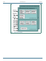
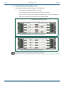
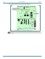
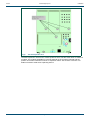
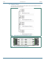
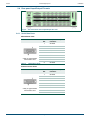
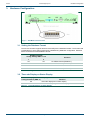
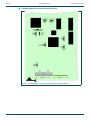
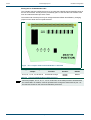
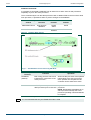
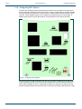
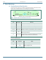
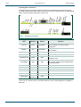
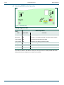
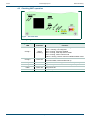
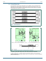
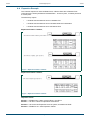
User Manual
Aurora
Router Control System
snellgroup.com
Aurora
Issue 6 Rev 1
www.snellgroup.com
Page 2
© 2013 Snell Limited
Aurora
www.snellgroup.com
Contents
Contents
1. Introduction. . . . . . . . . . . . . . . . . . . . . . . . . . . . . . . . . . . . . . . . . . . . . . . . . . . . . . . . . 7
2. Installation . . . . . . . . . . . . . . . . . . . . . . . . . . . . . . . . . . . . . . . . . . . . . . . . . . . . . . . . . 9
2.1 Installing and Removing Main Cards. . . . . . . . . . . . . . . . . . . . . . . . . . . . . . . . . . 10
2.2 Installing and Removing Input/Output Modules. . . . . . . . . . . . . . . . . . . . . . . . . . .11
2.3 Expansion Frames . . . . . . . . . . . . . . . . . . . . . . . . . . . . . . . . . . . . . . . . . . . . . . . 14
2.3.1 Expander Card Sub Modules . . . . . . . . . . . . . . . . . . . . . . . . . . . . . . . . . 15
2.4 Rear panel Input/Output Pin-outs . . . . . . . . . . . . . . . . . . . . . . . . . . . . . . . . . . . . 16
2.4.1 Serial Data Ports . . . . . . . . . . . . . . . . . . . . . . . . . . . . . . . . . . . . . . . . . . 16
2.4.2 Expansion Busses . . . . . . . . . . . . . . . . . . . . . . . . . . . . . . . . . . . . . . . . . 21
2.4.3 Timecode . . . . . . . . . . . . . . . . . . . . . . . . . . . . . . . . . . . . . . . . . . . . . . . . 22
2.4.4 Video Output . . . . . . . . . . . . . . . . . . . . . . . . . . . . . . . . . . . . . . . . . . . . . 23
3. Hardware Configuration. . . . . . . . . . . . . . . . . . . . . . . . . . . . . . . . . . . . . . . . . . . . . .
3.1 Setting the Database Format . . . . . . . . . . . . . . . . . . . . . . . . . . . . . . . . . . . . . . .
3.2 Timecode Display on Status Display . . . . . . . . . . . . . . . . . . . . . . . . . . . . . . . . . .
3.3 Enable/Disable Initial Router Tally Broadcast . . . . . . . . . . . . . . . . . . . . . . . . . . .
3.4 Setting the Status Display Standard . . . . . . . . . . . . . . . . . . . . . . . . . . . . . . . . . .
3.5 Configuration Switches 4 to 12 . . . . . . . . . . . . . . . . . . . . . . . . . . . . . . . . . . . . . .
3.6 Assigning Serial Ports . . . . . . . . . . . . . . . . . . . . . . . . . . . . . . . . . . . . . . . . . . . . .
3.7 Using Parallel Ports . . . . . . . . . . . . . . . . . . . . . . . . . . . . . . . . . . . . . . . . . . . . . . .
3.8 Changing Main Processor Board Options . . . . . . . . . . . . . . . . . . . . . . . . . . . . . .
3.9 Configuring 2638 Options . . . . . . . . . . . . . . . . . . . . . . . . . . . . . . . . . . . . . . . . . .
3.10 Configuring 2637 Options . . . . . . . . . . . . . . . . . . . . . . . . . . . . . . . . . . . . . . . . .
25
25
25
26
26
26
27
29
30
34
35
4. Status Monitoring . . . . . . . . . . . . . . . . . . . . . . . . . . . . . . . . . . . . . . . . . . . . . . . . . . .
4.1 Checking Processor Board Operation. . . . . . . . . . . . . . . . . . . . . . . . . . . . . . . . .
4.2 Checking 2638 Module Operation. . . . . . . . . . . . . . . . . . . . . . . . . . . . . . . . . . . .
4.3 Checking 2637 operation . . . . . . . . . . . . . . . . . . . . . . . . . . . . . . . . . . . . . . . . . .
37
37
40
41
5. Specification . . . . . . . . . . . . . . . . . . . . . . . . . . . . . . . . . . . . . . . . . . . . . . . . . . . . . . . 43
Appendix A. Aurora . . . . . . . . . . . . . . . . . . . . . . . . . . . . . . . . . . . . . . . . . . . . . . . . . . .
A.1 Single Frame – Internal Expansion. . . . . . . . . . . . . . . . . . . . . . . . . . . . . . . . . . .
A.2 Other Configurations for a Single Frame . . . . . . . . . . . . . . . . . . . . . . . . . . . . . .
A.3 External Expansion . . . . . . . . . . . . . . . . . . . . . . . . . . . . . . . . . . . . . . . . . . . . . . .
A.4 Expansion Example . . . . . . . . . . . . . . . . . . . . . . . . . . . . . . . . . . . . . . . . . . . . . .
Issue 6 Rev 1
Page 3
45
45
46
50
53
© 2013 Snell Limited
Aurora
Issue 6 Rev 1
www.snellgroup.com
Page 4
Contents
© 2013 Snell Limited
Aurora
www.snellgroup.com
Information and Notices
Information and Notices
Customer Support
United Kingdom (HQ)
+44 (0) 118 921 4214 (tel)
+44 (0) 118 921 4268 (fax)
[email protected]
Regional Support Contacts
Snell USA
+1 818 556 2616 (tel)
+1 818 556 2626 (fax)
[email protected]
Snell Germany
+49 (0) 6122 98 43 0 (tel)
+49 (0) 6122 98 43 44 (fax)
[email protected]
Snell Spain
+34 91 446 23 07 (tel)
+34 91 446 17 74 (fax)
[email protected]
Snell France
+33 1 41 95 30 50 (tel)
+33 1 41 95 30 51 (fax)
[email protected]
Snell Asia Pacific
+852 2356 1660 (tel)
+852 2575 1690 (fax)
[email protected]
Snell India
+91 124 462 6000 (tel)
+91 124 437 5888 (fax)
[email protected]
Snell Russia
+7 499 248 3443 (tel)
+7 499 248 1104 (fax)
[email protected]
Snell China
+86 10 6515 6158 (tel)
+86 10 6515 5659 (fax)
[email protected]
Customers with a support contract should call their personalized number, which can be found
in their contract, and be ready to provide their contract number and details.
Copyright and Disclaimer
Copyright protection claimed includes all forms and matters of copyrightable material and
information now allowed by statutory or judicial law or hereinafter granted, including without
limitation, material generated from the software programs which are displayed on the screen
such as icons, screen display looks etc.
Information in this manual and software are subject to change without notice and does not
represent a commitment on the part of Snell Ltd. The software described in this manual is
furnished under a license agreement and may not be reproduced or copied in any manner
without prior agreement with Snell Ltd. or their authorized agents.
Reproduction or disassembly of embedded computer programs or algorithms prohibited.
No part of this publication may be transmitted or reproduced in any form or by any means,
electronic or mechanical, including photocopy, recording or any information storage and
retrieval system, without permission being granted, in writing, by the publishers or their
authorized agents.
Snell operates a policy of continuous improvement and development. Snell reserves the right
to make changes and improvements to any of the products described in this document
without prior notice.
Issue 6 Rev 1
Page 5
© 2013 Snell Limited
Aurora
Issue 6 Rev 1
www.snellgroup.com
Page 6
Information and Notices
© 2013 Snell Limited
Aurora
www.snellgroup.com
Introduction
1. Introduction
Aurora is a self contained router control system capable of supporting a number of remote
control devices and matrices. For fail-safe operation in transmission environments,
redundancy is obtained by fitting dual processor cards and dual power supplies.
Each processor can be expanded within the main frame by adding an expander card via an
internal ribbon connector. Further expansion is possible by cascading up to eight expansion
frames. Each expansion frame can be fitted with up to two expander cards per processor.
The flexible assignment system allows the 32 assignable ports on a single frame to support a
variety of configurations. Normal configuration is for 16 control device ports, 16 matrix ports
and three remote control ports.
Smaller systems with fewer sub-boards and therefore less assignable ports can be built and
easily expanded later.
The full feature list is as follows:
Issue 6 Rev 1
•
Up to 32 assignable RS485 serial ports, 16 cue inputs and 32 cue outputs per main
6006 frame
•
Serial ports may be assigned to remote control, matrix and panel devices
•
Main and backup controller boards with controller expansion option
•
Expansion ports to cascade up to eight 6006 expansion frames
•
A fully expanded system can support up to 288 assignable serial ports, 144 cue inputs
and 288 cue outputs
•
Component analogue video output for status display
•
Active/standby control
•
Timecode lock
•
Two dedicated configuration and remote ports
•
Multi-standard reference loop through input
•
External power supply monitoring port
Page 7
© 2013 Snell Limited
Aurora
www.snellgroup.com
Fig 1.
Issue 6 Rev 1
Introduction
Aurora Overall Schematic
Page 8
© 2013 Snell Limited
Aurora
www.snellgroup.com
Installation
2. Installation
The 3U rack may be configured with a total of four main cards. Each card can accept
sub-boards according to the number of ports and the degree of redundancy required. It is
highly recommended to install a main and backup controller and a main and backup power
supply for fail-safe operation.
The following points should be observed during installation:
•
Remove shipping brackets
•
All rack equipment should be securely mounted
•
Ensure vents are unobstructed to allow cross-flow cooling
•
Power supplies are set for correct mains voltage
Shipping Brackets
Issue 6 Rev 1
Fig 2.
Front View Showing Shipping Brackets
Fig 3.
Side View Showing Ventilation Holes
Page 9
© 2013 Snell Limited
Aurora
www.snellgroup.com
Installation
2.1 Installing and Removing Main Cards
Take note of the following when installing and removing cards:
•
Each card has a dedicated position in the frame
•
Use card ejector handles to ease the task of removal or insertion
•
Avoid the use of excessive force, stiffness may indicate rear connector misalignment
•
Remember to replace internal expansion card cabling if fitted
Expansion Card Ribbon Cables
Note:
Issue 6 Rev 1
Fig 4.
The 6006 Aurora Main Frame Controller Card Positions
Fig 5.
The 6006 Aurora Expansion Frame Card Positions
Expansion frames do not require internal ribbon connectors.
Page 10
© 2013 Snell Limited
Aurora
www.snellgroup.com
Installation
2.2 Installing and Removing Input/Output Modules
Fig 6.
Note:
Issue 6 Rev 1
The 2633 Main Processor Showing Option Board Positions
Only 2637 serial I/O sub modules are used on the 2633 processor when used in the Aurora
frame.
Page 11
© 2013 Snell Limited
Aurora
www.snellgroup.com
Fig 7.
Note:
Issue 6 Rev 1
Installation
The 2633 Main Processor with Three 2637 Eight Port Serial Modules Fitted
Module orientation (DIL switch nearest board handles) when fitting modules. Each module
should be a gentle push-fit into its connectors. Four screws retain each module in position.
Page 12
© 2013 Snell Limited
Aurora
www.snellgroup.com
Fig 8.
Installation
The 2634 Expander Card
The 2634 expansion card has four module positions which can take either 2637 or 2638 sub
modules. The modules available for each slot depend on the functions required and the
position of the 2634 card when used in an expansion frame. See sections 3.2 and 3.4 for
details of modules used when expanding Aurora.
Issue 6 Rev 1
Page 13
© 2013 Snell Limited
Aurora
www.snellgroup.com
Installation
2.3 Expansion Frames
Up to eight Aurora frames fitted with 2634 expander cards, may be cascaded to the main
frame and used as expansion frames.
Fig 9.
System Expansion with Cascading Expansion Frames
Fig 10. The Aurora Expansion Frame Card Positions
Issue 6 Rev 1
Page 14
© 2013 Snell Limited
Aurora
www.snellgroup.com
Installation
2.3.1 Expander Card Sub Modules
For a single processor system either one or two 2634 expander cards are required for each
expansion frame depending upon requirements. A dual processor system can have two or
four 2634 expander cards fitted in each expansion frame.
2634 Expansion Sub Modules
Function
IC 1
IC 2
IC 3
IC 4
Main frame internal expansion
2637
2637
2638
Not Used
Expansion frame slot 1 (Exp A)
2637
2637
2638
Not Used
Expansion frame slot 2 (Exp A)
Not Used
Not Used
2637
2637
Expansion frame slot 3 (Exp B)
2637
2637
2638
Not Used
Expansion frame slot 4 (Exp B)
Not Used
Not Used
2637
2637
Table 1.
Important:
2634 Expansion Sub Modules
When 2637 sub modules are fitted in positions IC 1 and IC2, they are referred to as module
1 and 2 respectively, however when 2637 modules are fitted in positions IC3 and IC4, they
are referred to as module 2 and 1 respectively.
Fig 11. 64 Serial Ports, 32 Cue Inputs and 64 Cue Outputs with One Expansion Frame
Note:
Issue 6 Rev 1
Expansion frames are identical to Aurora main frames but with different boards. Only the
main frame provides a video output and requires reference and timecode inputs. Please
see section 3.2 for 2637 use in expanded systems.
Page 15
© 2013 Snell Limited
Aurora
www.snellgroup.com
Installation
2.4 Rear panel Input/Output Pin-outs
Fig 12. The Aurora Rear Panel Inputs/Output Pin Outs
2.4.1 Serial Data Ports
Matrix/Panel Ports
RS422/RS485 (Ports 1-32)
Pin
9 way ‘D’ type female
socket front view
Table 2.
Function
1
Chassis
2
RX-
3
TX+
4
GND
5
N/C
6
GND
7
RX+
8
TX-
9
Chassis
Matrix/Panel Ports
Remote Control Ports
RS422/RS485 (Ports 1-32)
Pin
9 way ‘D’ type female
socket front view
Table 3.
Issue 6 Rev 1
Function
1
Chassis
2
TX-
3
RX+
4
GND
5
N/C
6
GND
7
TX+
8
RX-
9
Chassis
Remote Control Ports
Page 16
© 2013 Snell Limited
Aurora
www.snellgroup.com
Installation
Config A/B
Config A/B *See following note
Pin
9 way ‘D’ type female
socket front view
Table 4.
Note:
RS485 Function
RS232 Function
1
Chassis
Chassis
2
TX-
TX
3
RX+
RX
4
Chassis
Chassis
5
N/C
N/C
6
Chassis
Chassis
7
TX+
N/C
8
RX-
N/C
9
Chassis
Chassis
Config A/B*
*See section 3.5 for setting the configuration port mode to either RS485 or RS232
Remote Ports 1 & 2
Remote Ports 1 & 2
Pin
9 way ‘D’ type female
socket front view
Table 5.
Function
1
Chassis
2
TX-
3
RX+
4
GND
5
N/C
6
GND
7
TX+
8
RX-
9
Chassis
Remote Ports 1 & 2
PSU Mon
PSU Mon
Pin
9 way ‘D’ type female
socket front view
Table 6.
Issue 6 Rev 1
Function
1
Chassis
2
Relay 1 Common
3
Relay 1 S/C
4
Relay 1 O/C
5
Relay 2 Common
6
Relay 2 S/C
7
Relay 2 O/C
8
N/C
9
N/C
PSU Mon
Page 17
© 2013 Snell Limited
Aurora
www.snellgroup.com
Installation
Active/Standby
Active/Standby
Pin
15 way ‘D’ type female
socket front view
Table 7.
Note:
Issue 6 Rev 1
Function
Specification
1
SET ACTIVE A
Active Low Input
2
SET IDLE A
Active Low Input
3
ACTIVE A
Logic Output
4
IDLE A
Logic Output
5
FAIL A
Logic Output
6
SET ACTIVE B
Active Low Input
7
SET IDLE B
Active Low Input
8
ACTIVE B
Logic Output
9
IDLE B
Logic Output
10
FAIL B
Logic Output
11
N/C
12
N/C
13
+5V LED Supply
14
GND
500 mA max current
Active/Standby
•
Active low inputs to be taken to 0V for correct operation.
•
Logic outputs are capable of sinking 3mA
Page 18
© 2013 Snell Limited
Aurora
www.snellgroup.com
2.4.1.1
Installation
Cue Inputs/Outputs
Cue Inputs
Cue Inputs 1 - 16
Pin
25 way ‘D’ type male
plug front view
Table 8.
Note:
Issue 6 Rev 1
Function
1
IN1
2
IN2
3
IN3
4
IN4
5
IN5
6
IN6
7
IN7
8
IN8
9
IN9
10
IN10
11
IN11
12
IN12
13
IN13
14
IN14
15
IN15
16
IN16
17
N/C
18
N/C
19
N/C
20
N/C
21
N/C
22
N/C
23
Supply Inputs 1 - 8
24
Supply Inputs 9 - 16
25
Chassis
Cue Inputs
Supply inputs may range from +5V to +15V. Current rating 0.5mA.
Page 19
© 2013 Snell Limited
Aurora
www.snellgroup.com
Installation
Cue Outputs
Cue Outputs 1 - 32
Pin
37 way ‘D’ type female
socket front view
Table 9.
Note:
Issue 6 Rev 1
Function
Pin
Function
1
Out 1
20
Out 20
2
Out 2
21
Out 21
3
Out 3
22
Out 22
4
Out 4
23
Out 23
5
Out 5
24
Out 24
6
Out 6
25
Out 25
7
Out 7
26
Out 26
8
Out 8
27
Out 27
9
Out 9
28
Out 28
10
Out 10
29
Out 29
11
Out 11
30
Out 30
12
Out 12
31
Out 31
13
Out 13
32
Out 32
14
Out 14
33
N/C
15
Out 15
34
N/C
16
Out 16
35
N/C
17
Out 17
36
N/C
18
Out 18
37
Chassis
19
Out 19
Cue Outputs
•
Cue outputs are open collector drivers and are all active low. They will accept
between +5V to +24V and will sink up to 40mA.
•
While configuration switches 4 to 9 and 11 to 12 (SW3: 4 to SW3: 8, SW4: 1 and
SW4:3 to SW4: 4) are not used they must be set to the UP position for correct system operation.
Page 20
© 2013 Snell Limited
Aurora
www.snellgroup.com
Installation
2.4.2 Expansion Busses
Upper (A) Main and Expansion Busses
Upper (A) Main and Expansion Busses
Pin
37 way ‘D’ type female
socket front view
Table 10.
Issue 6 Rev 1
Function
Pin
Function
1
RST +A
20
RST -A
2
IO +A
21
IO -A
3
SB +A
22
SB -A
4
FLG0 +A
23
FLG0 -A
5
FLG1 +A
24
FLG1 -A
6
FLG2 +A
25
FLG2 -A
7
ACC +A
26
ACC -A
8
EB0 +A
27
EB0 -A
9
EB1 +A
28
EB1 -A
10
EB2 +A
29
EB2 -A
11
EB3 +A
30
EB3 -A
12
EB4 +A
31
EB4 -A
13
EB5 +A
32
EB5 -A
14
EB6 +A
33
EB6 -A
15
EB7 +A
34
EB7 -A
16
EB8 +A
35
EB8 -A
17
N/C
36
N/C
18
N/C
37
Chassis
19
N/C
Upper (A) Main and Expansion Busses
Page 21
© 2013 Snell Limited
Aurora
www.snellgroup.com
Installation
Upper (B) Main and Expansion Busses
Upper (B) Main and Expansion Busses
Pin
37 way ‘D’ type female
socket front view
Table 11.
Function
Pin
Function
1
RST +B
20
RST -B
2
IO +B
21
IO -B
3
SB +B
22
SB -B
4
FLG0 +B
23
FLG0 -B
5
FLG1 +B
24
FLG1 -B
6
FLG2 +B
25
FLG2 -B
7
ACC +B
26
ACC -B
8
EB0 +B
27
EB0 -B
9
EB1 +B
28
EB1 -B
10
EB2 +B
29
EB2 -B
11
EB3 +B
30
EB3 -B
12
EB4 +B
31
EB4 -B
13
EB5 +B
32
EB5 -B
14
EB6 +B
33
EB6 -B
15
EB7 +B
34
EB7 -B
16
EB8 +B
35
EB8 -B
17
N/C
36
N/C
18
N/C
37
Chassis
19
N/C
Upper (B) Main and Expansion Busses
2.4.3 Timecode
LTC Input
9 way ‘D’ type male
plug front view
Table 12.
Issue 6 Rev 1
Pin
Function
1
LTC IN +
2
N/C
3
N/C
4
N/C
5
N/C
6
LTC IN -
7
Chassis
8
Chassis
9
Chassis
Timecode LTC Input
Page 22
© 2013 Snell Limited
Aurora
www.snellgroup.com
Installation
2.4.4 Video Output
(Presented as a Monochrome Signal)
Video Output
Pin
9 way ‘D’ type female
socket front view
Table 13.
Issue 6 Rev 1
Function
1
RED
2
N/C
3
BLUE
4
N/C
5
N/C
6
GREEN (Mono)
7
N/C
8
Sync
9
Chassis
Video Output
Page 23
© 2013 Snell Limited
Aurora
Issue 6 Rev 1
www.snellgroup.com
Page 24
Installation
© 2013 Snell Limited
Aurora
www.snellgroup.com
Hardware Configuration
3. Hardware Configuration
Fig 13. 2633 Main Processor Card
3.1 Setting the Database Format
The Aurora controller supports both Aurora and System 3 database formats. The format used
is dependent on which options have been enabled during database configuration. Switches
SW3-1 and SW3-2 set the database format.
Database Format
Config Settings SW3: 1 & 2
Function
1
2
UP
UP
SYSTEM3 format (DB303.01)
DOWN
UP
AURORA format (AUR01.00)
UP
DOWN
Reserved for future use
DOWN
DOWN
AURORA format (AUR01.01)
Table 14.
Setting the Database Format
3.2 Timecode Display on Status Display
Timecode Display on Status Display
Config Position 3 (SW3: 3)
UP
DOWN
Table 15.
Issue 6 Rev 1
Function
Timecode displayed on status display
Timecode not displayed on status display
Timecode Display on Status Display
Page 25
© 2013 Snell Limited
Aurora
www.snellgroup.com
Hardware Configuration
3.3 Enable/Disable Initial Router Tally Broadcast
Note:
The Enable/Disable Initial Router Tally Broadcast feature is available with firmware
version 1.24 and later.
Normally as Aurora does its background read of router tallies, if any are different, the new
status is broadcast to all the remote ports. On power-up, Aurora is reading one destination’s
crosspoint status every 20 ms, which means a command broadcast will be broadcast every
20 ms through each of the remote ports. The external devices connected to the remote ports
need to be able to process these commands at this rate (or faster).
If any of the remote devices cannot keep up with this rate, the internal buffers will start to fill
up and will block ports from getting responses to new commands until the backlog is cleared.
Once any of the buffers fill up, the commands will only empty at the rate the slowest external
device processes the commands.
To help get over this initial burst of data, the ability to disable the initial power-up broadcast of
crosspoint status has been added. This is configured using DIL switch 10 on the 2633
module.
Enable/Disable Initial Router Tally Broadcast
Config Position 10 (SW4: 2)
Table 16.
Note:
Function
UP
Initial Broadcast of router tallies is enabled
DOWN
Initial Broadcast of router tallies is disabled
Enable/Disable Initial Router Tally Broadcast
•
If the external devices do not have some sort of background refresh of crosspoint
status, there is a possibility that the external devices tallies could be out of sync
with the Aurora crosspoint tallies if the initial broadcast is disabled.
•
If during the initial poll of the routers by Aurora, there is no response to a tally
request for whatever reason, the initial poll state for the destinations on that router
port is cancelled which will cause the tallies to be broadcast to all remote ports
when the connection to that router section is re-established.
3.4 Setting the Status Display Standard
Status Display Standard
Config position 16 (SW4: 8)
Table 17.
Note:
Function
DOWN
525 lines mode
UP
625 lines mode
Setting the Status display Standard
The editor screen status display mode must agree with this switch setting.
3.5 Configuration Switches 4 to 12
While configuration switches 4 to 9 and 11 to 12 (SW3: 4 to SW3: 8, SW4: 1 and SW4: 3 to
SW4: 4) are not used they must be set to the UP position for correct system operation.
Issue 6 Rev 1
Page 26
© 2013 Snell Limited
Aurora
www.snellgroup.com
Hardware Configuration
3.6 Assigning Serial Ports
The 2637 serial port card can be used to provide Matrix, Device and Remote ports when used
on the 2633 main processor and 2634 expansion cards.
The configuration details are as follows:
Using the 2637card In the Main Frame
Assigning the 2637 Sub-Module Serial Ports
2633 Processor
Config Settings
(SW4: 5, 6, 7)
Note:
Issue 6 Rev 1
2637 position on
2633 Processor
2637 position on
2634 Expansion
IC 2
IC 1
Ports
Ports
25-32
17-24
Assignable Assignable
13
14
15
IC 1
Config
A/B*
Remote 1/2
UP
UP
UP
Remote 1/2
Device
Matrix
Device
Matrix
DOWN
UP
UP
Remote 1/2
Device
Device
Matrix
Matrix
UP
DOWN
UP
Remote 1/2
Device
Matrix
Matrix
Matrix
DOWN DOWN
UP
Remote 1/2
Device
Device
Device
Matrix
IC 2
Ports 1-8
Device
IC 3
Ports 9-16
Assignable
UP
UP
DOWN Remote 1/2
Device
Matrix
Remote
Matrix
DOWN
UP
DOWN Remote 1/2
Device
Matrix
Device
Remote
UP
DOWN DOWN Remote 1/2
Device
Table 18. Using the 2637card In the Main Frame
Matrix
Remote
Remote
•
The first port of the main processor IC1 sub module is wired to the ‘Config A’ port,
whilst the first port of the redundant processor IC1 sub-module is wired to the
‘Config B’ port. The remaining ports are wired to the sub-modules of main and
redundant systems in parallel.
•
The configuration switches 1 - 8 on the 2634 expansion card when fitted in the
main frame are not used and MUST be set to the DOWN position.
Page 27
© 2013 Snell Limited
Aurora
www.snellgroup.com
Hardware Configuration
Using the 2637 in Expansion Frames
Aurora can have up to 8 expansion frames. For a single processor system, either one or two
2634s are required, depending on port requirements. A dual processor system can have two
or four 2634 expander cards.
The 2634 card has 8 DIL switches on the front, used to configure the base address of the
card, the bus termination and the orientation of the 2637 sub modules base address. Each
2637 can run in one of the three modes, Matrix mode, Remote control mode and
Panel/Device mode. The mode of operation is determined by the switch setting on the 2634
card and the position of the 2637 card on the 2634 card, as defined on the table below.
Using the 2637 Sub-Modules in Expansion Frames
1
Switch Number
Use
Switches 1 to 5
Sub-Module Mode
2
3
4
5
DOWN DOWN DOWN DOWN DOWN
UP
DOWN DOWN DOWN DOWN
Sub-Module 1
Sub-Module 2
Local 2634, see 2633 DIL switch Table 18.
Device
Device
DOWN
UP
DOWN DOWN DOWN
Device
Device
UP
UP
DOWN DOWN DOWN
Device
Device
DOWN DOWN
UP
DOWN DOWN
Device
Device
UP
DOWN
UP
DOWN DOWN
Matrix
Matrix
DOWN
UP
UP
DOWN DOWN
Matrix
Matrix
UP
UP
UP
DOWN DOWN
Matrix
Matrix
DOWN DOWN DOWN
UP
DOWN DOWN
UP
DOWN
Matrix
Matrix
UP
DOWN
Matrix
Matrix
DOWN
UP
DOWN
UP
DOWN
Matrix
Matrix
UP
UP
DOWN
UP
DOWN
Matrix
Matrix
UP
UP
DOWN
Matrix
Matrix
DOWN DOWN
UP
DOWN
UP
UP
DOWN
Remote
Remote
DOWN
UP
UP
UP
DOWN
Device
Matrix
UP
UP
UP
UP
DOWN
Device
Remote
UP
Remote
Matrix
DOWN DOWN DOWN DOWN
Switch 6
Not Used
UP for any 2634 occupying a 2633 slot (slots 2
and 4)
Switch 7
DOWN for any 2634 occupying a 2634 slot
(slots 1 and 3)
UP - Terminate the BUS.
PLEASE NOTE - For an expanded System,
one of the 2634’s in the last frame should have
this switch UP. If a backup system is used, then
one 2634 in each system should have this
switch on.
Switch 8
Table 19.
Note:
Issue 6 Rev 1
Using the 2637 Sub-Modules in Expansion Frames
Switch 7 on the 2634 must be UP to let the hardware know that this 2634 occupies a 2633
position, otherwise the software will not find the sub modules. This is because of the
manner in which the ports physically map to the connectors on the backplane.
Page 28
© 2013 Snell Limited
Aurora
www.snellgroup.com
Hardware Configuration
Fig 14. Using the 2634 Expander Card in Expansion Frames
Note:
If a 2634 card in an expansion frame occupies slots 2 or 4, the slots that a 2633 controller
card normally occupies, then the sub modules must be in positions IC4 and IC3 for sub
module 1 and 2 respectively. If the 2634 card is used in slots 1 or 3 of an expansion frame,
then the 2637 sub module must occupy IC1 and IC2 respectively.
3.7 Using Parallel Ports
The 2638 module is an intelligent parallel I/O card with 16 optically isolated inputs and 32
collector driver outputs. It is used to interface GPI triggers and other parallel data to external
equipment.
The 2638 sub module may only be used on the 2634 expander card in position IC3. However,
there are rules defining the deployment of the card in expanded systems. Please see section
2.3, for details of 2638 sub module when used in Aurora expansion.
Issue 6 Rev 1
Page 29
© 2013 Snell Limited
Aurora
www.snellgroup.com
Hardware Configuration
3.8 Changing Main Processor Board Options
Fig 15. The 2633 Main Processor Card CPU and Video Option Jumpers
Issue 6 Rev 1
Page 30
© 2013 Snell Limited
Aurora
www.snellgroup.com
Hardware Configuration
Setting CPU and Video Processor Options
Processor Options
Jumper
Function
Position
Default
PL7
FLASH/ROM
FLASH
ROM
ROM
PL8
RAM/ROM
RAM
ROM
ROM
PL10
CACHE
DISABLE
ENABLE
ENABLE
PL11
VIDCLK
SLOW
FAST
FAST
PL 12
68030 CLK
FAST
SLOW
FAST
PL14
TEST
NORM
TEST
NORM
PL23
CPU SELECT
68030
68000
68030
PL24
BOOT
RUN
OFF
RUN
Table 20.
Setting CPU and Video Processor Options
Setting Watchdog Options
Watchdog Settings
Jumper
Function
Position
Default
PL9
WATCHDOG
ON
OFF
ON
PL21
WATCHDOG
ON
OFF
ON
Table 21.
Issue 6 Rev 1
Setting Watchdog Options
Page 31
© 2013 Snell Limited
Aurora
www.snellgroup.com
Hardware Configuration
Setting the PC CONFIG A/B modes
The controller may be configured from a PC by using the CONFIG A and CONFIG B ports at
the rear of the frame. These ports are provided by port 1 of the first 2637 sub module of the
main and redundant 2633 processor cards.
The serial mode of these ports may be changed between RS232 and RS485 by changing
jumpers on the 2633 card as explained below:
Fig 16. Port 1 Jumpers Under Central I/O Module on 2633 Card
Config Port Mode Setting on Main Processor
Jumper
Function
Position
Default
PL15, 16, 17, 18, 19, 20 and 22
Port Mode Change
RS485
RS232
RS232
Table 22.
Note:
Issue 6 Rev 1
Config Port Mode Setting on Main Processor
All seven jumpers, PL 15, 16, 17, 18, 19, 20 and 22, on the 2633 processor located under
the central 2637 I/O module, must be repositioned to change the serial mode of port 1 of
the first sub-module on the main and redundant processors.
Page 32
© 2013 Snell Limited
Aurora
www.snellgroup.com
Hardware Configuration
Database Downloads
It is possible to download a database from an editor PC to either active or idle processors
separately or just to the active processor.
This is controlled by PL6 on the 2633 processor card. In addition SW2 on the front of the 2633
main processor, is provided to allow or prevent changes to the database.
Database Write Options
Control
Function
Position
Default
PROG/SAFE SW 2
Write protects
database
PROG
SAFE
SAFE
PL 6
RS485 Inhibit
Dual
Enabled
Enabled
Table 23.
Database Write Options
Fig 17. 2633 Database Protect and Config A/B Mode
PL 6 Jumper
Position
Issue 6 Rev 1
Operation
ENABLED
(default)
Both config ports are active and
independent, irrespective of the
active processor
DUAL
ACTIVE processor port is active - Updates are downloaded to active
IDLE processor port is not active processor.
NOTE: Downloading a database to an
active processor will stop the active
processor operating until the download
is complete
Table 24.
Note:
Function
Allows the idle processor to be updated
independent of the active processor.
Once updates are complete the idle
controller can be switched to active.
PL 6 Jumper Position
It is recommended that only the ENABLED mode is used
Page 33
© 2013 Snell Limited
Aurora
www.snellgroup.com
Hardware Configuration
3.9 Configuring 2638 Options
The 2638 interface provides 32 open collector output lines and 16 optically isolated input
lines. It can occupy position IC3 of a 2634 expander card in a main frame and the IC3 position
of a 2634 card when used in slot 2 or 4 of an expansion frame.
Fig 18. Configuring 2638 Options
Setting the Default Output Pulse Length
SW1 configuration
OFF = lever down (nearest bottom card edge)
Default Pulse Duration
SW1
SW2
10 milliseconds
0
0
100 milliseconds
0
1
Video Frames
1
0
Reserved
1
1
Table 25.
Setting the Default Output Pulse Length
SW3 and SW4 are not currently used but should be off for compatibility with future releases of
the software.
The default pulse duration value may be overridden by software.
Enabling the Watchdog
Watchdog - PL4
Function
Position
Watchdog Enabled
ON (Default)
Watchdog Disabled
OFF
Table 26.
Enabling the Watchdog
Setting the Processor Mode
Processor Mode- PL5
Function
Position
Norm
Test
Table 27.
Issue 6 Rev 1
Norm (Default)
For test purposes only
Setting the Processor Mode
Page 34
© 2013 Snell Limited
Aurora
www.snellgroup.com
Hardware Configuration
3.10 Configuring 2637 Options
The 2637 sub module provides eight serial ports which can be configured according to the
mode of operation selected by the host processor. These normal modes of operation include
the multi-drop device interface, the router control or matrix interface and the remote control
interface. A flash EPROM mode is also available for programming the on-board RAM. In
addition several factory test modes exist for Snell engineers to test card functionality.
Fig 19. Configuring 2637 Options
On power up all ports will be disabled until the host processor initializes and configures the
mode of operation for the ports. However, port hardware set up can be determined by DIL
switch SW1 in addition to the PC configuration jumpers (see Table 28. on page 36) for the
first port (CONFIG A/B) of the first 2637 card on the main and backup 2633 processor cards.
Issue 6 Rev 1
Page 35
© 2013 Snell Limited
Aurora
www.snellgroup.com
Hardware Configuration
Configuring Port Hardware Settings
Switch SW1 Settings
Multi-drop Device
Router (Matrix) Control
Remote Control
OFF
ON
OFF
ON
OFF
ON
SW1-1
4 Wire
Circuit
2 Wire
Circuit
38.4 kBaud
for Port 1
9.6 kBaud
for Port 1
38.4 kBaud
for Port 1
19.2 kBaud
for Port 1
SW1-2
Not Used
Not Used
38.4 kBaud
for Port 2
9.6 kBaud
for Port 2
38.4 kBaud
for Port 2
19.2 kBaud
for Port 2
SW1-3
38.4 kBaud 9.6 kBaud 38.4 kBaud
for Ports 1-4 for Ports 1-4 for Port 3
9.6 kBaud
for Port 3
38.4 kBaud
for Port 3
19.2 kBaud
for Port 3
SW1-4
38.4 kBaud 9.6 kBaud 38.4 kBaud
for Ports 5-8 for Ports 5-8 for Port 4
9.6 kBaud
for Port 4
38.4 kBaud
for Port 4
19.2 kBaud
for Port 4
Table 28.
Configuring Port Hardware Settings
Default settings irrespective of board function is all OFF.
Setting Card Defaults
The following table lists the default settings for system jumpers located on the sub module:
2637 Processor Options
Mode
Jumper
Function
Default
Norm
Test
PL8
Factory Test
Norm
RAM
ROM
PL4
RAM/ROM Selection
ROM
27040
27256
PL7
Device Selection
27040
FAST
SLOW
PL6 CLK
CPU Clock Selection
FAST
FLASH
ROM
PL5
Device Selection
ROM
ON
OFF
PL3
Watchdog
ON
Table 29.
Issue 6 Rev 1
Setting Card Defaults
Page 36
© 2013 Snell Limited
Aurora
www.snellgroup.com
Status Monitoring
4. Status Monitoring
4.1 Checking Processor Board Operation
The 2633 processor card has 16 software programmable diagnostic LEDs which indicate
system modes, hardware/software errors and diagnostic information.
Diagnostic LEDs on the 2633 Main Processor Card
Fig 20. Diagnostic LEDs on the 2633 Main Processor Card
Reading Diagnostic Indicators
System Diagnostic Indicators
LED
Indication
9
ON
No response to tally request on matrix ports 1 - 8
10
ON
No response to tally request on matrix ports 9 -16
9 & 10
BOTH ON
11
ON
Unable to TX data to a control device on port 1 - 8
12
ON
Unable to TX data to a control device on port 9 - 16
11 & 12
BOTH ON
13
ON
Destination is not assigned to a matrix port
14
ON
General fault - an internal buffer is full or some unexpected
data has been detected
15
FLASHING
Data being transferred successfully between ACTIVE and
IDLE processors. This will only be flashing on the ACTIVE
processor, It will be OFF on the IDLE processor
16
Table 30.
ON
Meaning
No response to tally request on matrix ports 17 and above
Unable to TX data to a control device on port 17 and above
External timecode is present
Diagnostic Indicators
Confirming System Modes
System LEDs 1 to 4
LED
Indication
1&2
Flashing Alternately
1&2
Flashing Together
3
ON
OFF
4
Flashing
Table 31.
Issue 6 Rev 1
Mode
System running in ACTIVE mode
System running in IDLE mode
Invalid or corrupt system database
System database is OK
Downloading database from PC
Confirming System Modes
Page 37
© 2013 Snell Limited
Aurora
www.snellgroup.com
Status Monitoring
Checking Hardware and Software Errors
LEDs 5-8 indicate hardware and software errors. Normally all 4 LEDs should be OFF
indicating normal system operation.
Internal Hardware/Software Errors
LED Number
6
7
8
OFF
OFF
OFF
OFF
No error - normal system state
OFF
ON
OFF
OFF
Bus error
ON
ON
OFF
OFF
Address error
OFF
OFF
ON
OFF
Illegal instruction error
ON
OFF
ON
OFF
Divide by zero error
OFF
ON
ON
OFF
CHK instruction error
ON
ON
ON
OFF
TRAPV instruction error
OFF
OFF
OFF
ON
Privilege violation error
ON
OFF
OFF
ON
Trace error
OFF
ON
OFF
ON
Unexpected interrupt error
ON
ON
OFF
ON
Spurious interrupt error
OFF
ON
ON
Un-initialized interrupt error
OFF
Table 32.
Issue 6 Rev 1
LED Function
5
Checking Hardware and Software Errors
Page 38
© 2013 Snell Limited
Aurora
www.snellgroup.com
Status Monitoring
Checking Basic Functions
The 2633 processor and 2634 expansion cards have the following LEDs and test points
provided to allow monitoring of basic functions such as power, reference lock, and operational
status. Some indicators are specific to each card.
Fig 21. 2633 & 2634 Card LEDs
Checking Basic Functions
LED
Indication
Board
ACTIVE
Green
2633/2634
Lights to indicate that the board is in the
active condition in a dual processor
configuration
RESET
Red
2633/2634
Lights to indicate that the system is in a
reset condition
REF LCKD
Yellow
2633
Lights to indicate reference lock
625
Yellow
2633
Lights for 625, off for 525 reference
VIDPROC OK
Yellow
2633
Flashes to indicate that the video
processor is OK
VID RESET
Red
2633
Lights to indicate that the video processor
is in a reset condition (LED located behind
right board handle)
ACCESS
Yellow
2634
Monitors ACCESS line
VALID
Yellow
2634
Monitors VALID line
SUB PWR
Green
2633
Monitors Sub +5V rail (test point available)
MAIN PWR
Green
2633
Monitors +5V rail (test point available)
POWER
Green
2634
Monitors +5V rail (test point available)
TIMECODE
Yellow
(DIAG16)
2633
Table 33.
Function
Lights to indicate timecode present
2633 & 2634 LEDs
The 9 way ‘D’ connector, SK1 on the 2633 card is for use by Snell engineers to update the
flash-rom.
Issue 6 Rev 1
Page 39
© 2013 Snell Limited
Aurora
www.snellgroup.com
Status Monitoring
4.2 Checking 2638 Module Operation
Fig 22. 2638 Card LEDs
Reading Diagnostic LEDs
Diagnostic
LEDs
LED
Normal Operation
Indication
Function
Config 1
Yellow Flashing Module running, flash rate indicates mode:-
Idle Mode
1 Hz
Idle mode - host 2634 is backup in dual processor system
Active Mode 2 Hz
Active and scanning Dual Port RAM
Active Mode 4 Hz
Active but not scanning Dual Port RAM
Config 2
Yellow Flashing Input data changes detected
Config 3
Yellow Flashing Output data changes detected
Config 4
Yellow Flashing Flashes at 1/10 input scan rate
PWR
Table 34.
Green On
+5V power OK
2638 LEDs
The Dual Port RAM on the 2638 is used by the host processor to buffer parallel data either
being read from the 2638 inputs or written to its outputs.
Issue 6 Rev 1
Page 40
© 2013 Snell Limited
Aurora
www.snellgroup.com
Status Monitoring
4.3 Checking 2637 operation
Fig 23. 2637 Card LEDs
Reading Diagnostic LEDs
Diagnostic LEDs
LED
Indication
Function
Config 1
Yellow
Flashing
Flashes to indicate processor running:10Hz = running, not configured
5Hz = running, serial I/O disabled
2Hz = running, multi-drop device mode
1Hz = running, router control mode
0.5Hz = running, remote control mode/flash loader mode
Config 2
Yellow On
Fault indicator:Erroneous data, internal buffers full up
Config 3
Yellow On
Lights if valid Rx messages received on any serial port
Config 4
Yellow On
Lights if any Tx data transmitted on any serial port
PWR
Green On
+5V power OK
RST
Red On
Table 35.
Issue 6 Rev 1
Normal Operation
Indicates processor reset
2637 LEDs
Page 41
© 2013 Snell Limited
Aurora
Issue 6 Rev 1
www.snellgroup.com
Page 42
Status Monitoring
© 2013 Snell Limited
Aurora
www.snellgroup.com
Specification
5. Specification
Main Features
•
Up to 32 assignable RS485 serial ports, 16 cue inputs and 32 cue outputs in the main
frame
•
Serial ports may be flexibly assigned to matrix, panel, and remote control devices
•
Main and backup controller boards with controller expansion option
•
Component analogue video output for status display
•
Active/standby control
•
Timecode lock
•
Two dedicated configuration and remote ports
•
Multi-standard reference loop through input
•
External power supply monitoring port
•
Status monitoring on each module
Expansion Capability
•
Support for three 8 port serial cards on each controller card
•
Support for two 8 port serial cards on each controller expansion card
•
Support for 16 cue inputs and 32 cue outputs per main frame controller expansion
card
•
Expansion ports to cascade up to eight Aurora expansion frames
•
Each expander card in an expansion frame can support up to sixteen serial ports
•
Each expansion frame can support an additional 16 cue inputs and 32 cue outputs
•
A fully expanded system with one main frame and 8 expansion frames can support up
to 288 assignable serial ports, 144 cue inputs and 288 cue outputs
Connectors
(see section 2.4 for pin-outs)
Issue 6 Rev 1
•
RS422/RS485/RS232: 9 way ‘D’ type sockets
•
Cue inputs: 25 way ‘D’ type socket, 16 active low inputs with a separate supply input
of +5V to +15V at 0.5 mA
•
Cue outputs: 37 way ‘D’ type socket, 32 active low collector driver outputs, each capable of accepting between +5V to +24V and will sink a maximum of 40 mA
•
Active/standby: 15 way ‘D’ type plug, inputs are active low and logic outputs are capable of sinking 3mA, the +5V LED output will supply 500 mA
•
Video: BNC
•
Timecode: 9 way ‘D’ plug
•
Reference loop through: BNC
Page 43
© 2013 Snell Limited
Aurora
www.snellgroup.com
Specification
Power
•
110/220/240V AC 10%
•
Fully equipped 50/60Hz at 100VA
•
Dual power supply configuration
Mechanical
•
Frame: 3U 19” rack frame
•
Width: 483mm
•
Depth: 490mm
•
Height: 133mm
•
Weight: 7.2kg (frame and power supplies), 10.5 kg (fully equipped frame and power
supplies)
General
•
Issue 6 Rev 1
Temperature range: 0°C to +40°C
Page 44
© 2013 Snell Limited
Aurora
www.snellgroup.com
Aurora
Appendix A. Aurora
A.1 Single Frame – Internal Expansion
The diagrams below show the 2633 & 2634 positions in a Fully Populated Aurora Frame.
Switches on these cards determine the function of the relevant ports on the rear of the frame.
The switch settings in Fig 24. show the Factory Default settings. Other switch/port
configurations are discussed later.
Configuration 1: 16 Device (panels) Ports, 16 Matrix Ports, 2 Remote Ports
(factory default)
Fig 24. Configuration 1: 16 Device (panels) Ports, 16 Matrix Ports, 2 Remote Ports
Note:
Issue 6 Rev 1
•
If the 2633 card is used without a 2634 card the Aurora frame has 8 Device
(panels) Ports, 8 Matrix Ports, 2 Remote Ports
•
No backup Processor is fitted if Slot 3 and Slot 4 are empty.
Page 45
© 2013 Snell Limited
Aurora
www.snellgroup.com
Aurora
A.2 Other Configurations for a Single Frame
It is possible to change the switches on the 2633 card to suit a number system environments.
Changing the switches 13, 14, 15 on the 2633 modifies the ‘mix’ of ports on the rear of the
Aurora Controller.
The switches on the 2634 should remain set to the down position.
Note:
For Clarity only the switch settings of one of the 2633 cards is shown. Both 2633 cards
must be set identically.
Configuration 2: 16 Device Ports, 16 Matrix Ports & 2 Remote Ports
Fig 25. Configuration 2: 16 Device Ports, 16 Matrix Ports & 2 Remote Ports
Issue 6 Rev 1
Page 46
© 2013 Snell Limited
Aurora
www.snellgroup.com
Aurora
Configuration 3: 8 Device Ports, 24 Matrix Ports, 2 Remote Ports
Fig 26. Configuration 3: 8 Device Ports, 24 Matrix Ports, 2 Remote Ports
Configuration 4: 24 Device Ports, 8 Matrix Ports and 2 Remote Ports
Fig 27. Configuration 4: 24 Device Ports, 8 Matrix Ports and 2 Remote Ports
Issue 6 Rev 1
Page 47
© 2013 Snell Limited
Aurora
www.snellgroup.com
Aurora
Configuration 5: 8 Device Ports, 16 Matrix Ports, 6 Remote Ports
Fig 28. Configuration 5. 8 Device Ports, 16 Matrix Ports, 6 Remote Ports
Configuration 6: 16 Device Ports, 8 Matrix Ports, 6 Remote Ports
Fig 29. Configuration 6. 16 Device Ports, 8 Matrix Ports, 6 Remote Ports
Issue 6 Rev 1
Page 48
© 2013 Snell Limited
Aurora
www.snellgroup.com
Aurora
Configuration 7: 16 Device Ports, 4 Matrix Ports, 10 Remote Ports
Fig 30. Configuration 7. 16 Device Ports, 4 Matrix Ports, 10 Remote Ports
Issue 6 Rev 1
Page 49
© 2013 Snell Limited
Aurora
www.snellgroup.com
Aurora
A.3 External Expansion
Each Expansion Frame can be configured for a mix of Matrix, Device and Remote Ports
depending on the switch settings on the front of the 2634 card. Each 2634 in slot 1 (or 3)
allows extra Cues to be added. As with the Main Processor Frame, if there are no backup
cards required slot 3 and slot 4 are empty.
Fig 31. External Expansion
Sub Module 2637 Positions and Physical Rear Port Number
Fig 32. Sub Module 2637 Positions and Physical Rear Port Number
For Clarity only the switch settings of the 2634 cards in Expander A are shown.
If using a backup pair, the relevant switches of Expander B must be set to the identical
settings of Expander A. The switch settings of Slot 1 must match Slot 3, the switch settings of
Slot 2 must match Slot 4.
Issue 6 Rev 1
Page 50
© 2013 Snell Limited
Aurora
www.snellgroup.com
Aurora
Expansion Frame Switch Settings:
Adding Device ports;
Each 2634 adds 16 Device ports when configured as shown in Table 36.
Device Ports
SW1
SW2
SW3
SW4
SW5
to add 1st 16
UP
DOWN
DOWN
DOWN
DOWN
to add 2nd 16
DOWN
UP
DOWN
DOWN
DOWN
to add 3rd 16
UP
UP
DOWN
DOWN
DOWN
to add 4th 16
DOWN
DOWN
UP
DOWN
DOWN
Table 36.
Adding Device Ports
Adding Matrix ports;
Each 2634 adds 16 Matrix ports when configured as shown in Table 37.
Matrix Ports
SW1
SW2
SW3
SW4
SW5
to add 1st 16
UP
DOWN
UP
DOWN
DOWN
to add 2nd 16
DOWN
UP
UP
DOWN
DOWN
to add 3rd 16
UP
UP
UP
DOWN
DOWN
to add 4th 16
DOWN
DOWN
DOWN
UP
DOWN
to add 5th 16
UP
DOWN
DOWN
UP
DOWN
to add 6th 16
DOWN
UP
DOWN
UP
DOWN
to add 7th 16
UP
UP
DOWN
UP
DOWN
to add 8th 16
DOWN
DOWN
UP
UP
DOWN
Table 37.
Adding Matrix Ports
Adding Remote ports;
The 2634 adds 8 Remote ports when configured as shown in Table 38.
Remote Ports
SW1
SW2
SW3
SW4
SW5
to add 8 Ports
UP
DOWN
UP
UP
DOWN
Table 38.
Adding Remote ports
Special Combinations
It is possible to add a combination of Device/Matrix/Remote ports using the 2634 card.
The 2634 adds a mix of 8 Device 8 Matrix 4 Remote ports when configured as shown in
Table 39.
Note:
As these special combinations may only be used once in each system, it is best to expand
Aurora controllers in blocks of 16 Device or Matrix ports.
Sub Module 1 (IC4)
Sub Module 2 (IC3)
SW1
SW2
SW3
SW4
SW5
to add 8 Device Ports
AND 8 Matrix Ports
DOWN
UP
UP
UP
DOWN
to add 8 Device Ports
AND 4 Remote Ports
UP
UP
UP
UP
DOWN
to add 4 Remote Ports
AND 8 Matrix Ports
Table 39.
DOWN DOWN DOWN DOWN
UP
Special Combinations
When adding to an existing Expanded System, use 2634 switch settings that have not been
used in the original set-up.
Issue 6 Rev 1
Page 51
© 2013 Snell Limited
Aurora
www.snellgroup.com
Aurora
Expansion Frame Termination
The final Expansion frame MUST BE TERMINATED. The termination is set by sw8
Switch 8 = UP for the last Expansion frame in system, terminates the BUS
Switch 8 = DOWN for ALL other Expansion frames
Issue 6 Rev 1
Page 52
© 2013 Snell Limited
Aurora
www.snellgroup.com
Aurora
A.4 Expansion Example
The customer requires an extra 24 Matrix Ports, 8 Device Ports and 4 Remote Ports
connected to the Factory default Aurora Mainframe - 16 device ports, 16 matrix ports and
2 remote ports.
Therefore they require
•
1 off 2634 with the switches set as a 16 Matrix Port
•
1 off 2634 with the switches set as a 8 Matrix-8 Device Combination
•
1 off 2634 with the switches set as a 8 Remote Port
Expansion Frame 1 Contains;
Fig 33. Expansion Frame 1 Contains
Expansion Frame 2 Contains;
Fig 34. Expansion Frame 2 Contains
Important Points:
Switch 7 = DOWN when a 2634 occupies Slots 1 and Slot 3
Switch 7 = UP when a 2634 occupies Slots 2 and Slot 4
Switch 8 = UP for the last Expansion frame in system, terminates the BUS
Switch 8 = DOWN for ALL other Expansion frames
Issue 6 Rev 1
Page 53
© 2013 Snell Limited
Aurora
Issue 6 Rev 1
www.snellgroup.com
Page 54
Aurora
© 2013 Snell Limited