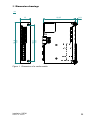
1
User Manual Installation Industrial Ethernet Rail Switch Power Media Module RSPM Installation RSPM Release 08 08/2014 Technical Support https://hirschmann-support.belden.eu.com The naming of copyrighted trademarks in this manual, even when not specially indicated, should not be taken to mean that these names may be considered as free in the sense of the trademark and tradename protection law and hence that they may be freely used by anyone. © 2014 Hirschmann Automation and Control GmbH Manuals and software are protected by copyright. All rights reserved. The copying, reproduction, translation, conversion into any electronic medium or machine scannable form is not permitted, either in whole or in part. An exception is the preparation of a backup copy of the software for your own use. For devices with embedded software, the end-user license agreement on the enclosed CD/DVD applies. The performance features described here are binding only if they have been expressly agreed when the contract was made. This document was produced by Hirschmann Automation and Control GmbH according to the best of the company's knowledge. Hirschmann reserves the right to change the contents of this document without prior notice. Hirschmann can give no guarantee in respect of the correctness or accuracy of the information in this document. Hirschmann can accept no responsibility for damages, resulting from the use of the network components or the associated operating software. In addition, we refer to the conditions of use specified in the license contract. You can get the latest version of this manual on the Internet at the Hirschmann product site (www.hirschmann.com). Printed in Germany Hirschmann Automation and Control GmbH Stuttgarter Str. 45-51 72654 Neckartenzlingen Germany Tel.: +49 1805 141538 RSPM 040 044-001-08-0814 -30.07.2014 Contents Safety instructions 5 About this manual 8 Key 8 1 Description 9 1.1 General description 9 1.2 Device name and product code 10 1.3 Combination options 13 1.4 Media module variants 1.4.1 Port configuration 1.4.2 Media module slots on the RSPE device 14 14 15 1.5 Ethernet ports 1.5.1 100 Mbit/s F/O port 1.5.2 10/100 Mbit/s twisted pair port 1.5.3 Support of PoE and PoE+ 15 15 16 16 1.6 Display elements 1.6.1 Media module status 1.6.2 Port state 18 18 19 2 Installation 20 2.1 Unpacking and checking the content of the package 20 2.2 Mounting a media module 20 2.3 Installing an SFP transceiver (optional) 21 2.4 Connecting data cables 21 3 Maintenance and service 22 4 Disassembly 23 4.1 Removing an SFP transceiver (optional) 23 4.2 Removing a media module 23 5 Technical data 24 A Further Support 33 Installation RSPM Release 08 08/2014 3 4 Installation RSPM Release 08 08/2014 Safety instructions General safety instructions You operate this device with electricity. The proper and safe operation of this device depends on proper handling during transportation, proper storage and installation, and careful operation and maintenance procedures. Improper usage of the device entails the risk of physical injury or significant property damage. Before connecting any cable, read this document, and the safety instructions and warnings. Operate the device with undamaged components exclusively. Follow precisely the prescribed safety requirements for the voltage connections. You will find detailed information regarding the voltage supply in the “User Manual Installation RSPE”. The device is free of any service components. In case of a damaged or malfunctioning the device, turn off the working voltage and return the device to Hirschmann for inspection. Qualification requirements for personnel Only allow qualified personnel to work on the device. Qualified personnel have the following characteristics: Qualified personnel are properly trained. Training as well as practical knowledge and experience make up their qualifications. This is the prerequisite for grounding and labeling circuits, devices, and systems in accordance with current standards in safety technology. Qualified personnel are aware of the dangers that exist in their work. Qualified personnel are familiar with appropriate measures against these hazards in order to reduce the risk for themselves and others. Qualified personnel receive training on a regular basis. Certified usage Use the device solely for the application cases described in the Hirschmann product information, including this manual. Operate the device solely according to the technical specifications. See “Technical data” on page 24. National and international safety regulations Verify that the electrical installation meets local or nationally applicable safety regulations. Shielded ground The shielded ground wire of the twisted pairs cables is connected to the front panel as a conductor. Beware of possible short circuits when connecting a cable section with conductive shield braiding. Installation RSPM Release 08 08/2014 5 ESD Guidelines The modules are equipped with electrostatically sensitive components. These can be destroyed, or their life cycles reduced, by the effects of an electrical field or by a charge equalization if the connections are touched. You will find information about electrostatically endangered assemblies in DIN EN 61340-5-1 (2007-08) and DIN EN 61340-5-2 (2007-08). CE marking The statements in this chapter refer only to media modules which are completely and correctly mounted in a RSPE device (see on page 20 “Mounting a media module”). The labeled devices comply with the regulations contained in the following European directive(s): 2011/65/EU (RoHS) Directive of the European Parliament and of the Council on the restriction of the use of certain hazardous substances in electrical and electronic equipment. 2004/108/EC (EMC) Directive of the European Parliament and the council for standardizing the regulations of member states with regard to electromagnetic compatibility. In accordance with the above-named EU directive(s), the EU conformity declaration will be at the disposal of the relevant authorities at the following address: Hirschmann Automation and Control GmbH Stuttgarter Str. 45-51 72654 Neckartenzlingen Germany Tel.: +49 1805 141538 The device can be used in the industrial sector. Interference immunity: EN 61000-6-2 Emitted interference: EN 55022 Reliability: EN 60950-1 You find more information on technical and industry standards here: “Technical data” on page 24 Warning! This is a class A device. This device can cause interference in living areas, and in this case the operator may be required to take appropriate measures. 6 Installation RSPM Release 08 08/2014 LED or laser components LED or LASER components according to IEC 60825-1 (2007): CLASS 1 LASER PRODUCT CLASS 1 LED PRODUCT Note: You will find additional warning and safety information in the “User Manual Installation RSPE”. FCC note: The statements in this chapter refer only to media modules which are completely and correctly mounted in a RSPE device (see on page 20 “Mounting a media module”). This device complies with part 15 of the FCC rules. Operation is subject to the following two conditions: (1) this device may not cause harmful interference; (2) this device must accept any interference received, including interference that may cause undesired operation. Appropriate testing has established that this device fulfills the requirements of a class A digital device in line with part 15 of the FCC regulations. These requirements are designed to provide sufficient protection against interference when the device is being used in a business environment. The device creates and uses high frequencies and can also radiate these frequencies. If it is not installed and used in accordance with this operating manual, it can cause radio transmission interference. The use of this device in a residential area can also cause interference, and in this case the user is obliged to cover the costs of removing the interference. Recycling note After usage, this device must be disposed of properly as electronic waste, in accordance with the current disposal regulations of your county, state, and country. Installation RSPM Release 08 08/2014 7 About this manual The “Installation” user manual contains a device description, safety instructions, a description of the display, and the other information that you need to install the device. Key The symbols used in this manual have the following meanings: 8 Listing Work step Subheading Installation RSPM Release 08 08/2014 1 1.1 Description General description You can choose from between a wide range of variants. You have the option to set up your device individually based on different criteria: Types of connectors Support of PoE and PoE+ Temperature range Certifications The RSPM media modules are designed for the special requirements of industrial automation. They meet the relevant technical standards, provide very high operational reliability, even under extreme conditions, and also long-term reliability and flexibility. You have the option of choosing various media to connect to the terminal devices and other network components: Multimode optical fiber Singlemode optical fiber Twisted pair cable Installation RSPM Release 08 08/2014 9 1.2 Device name and product code Item Characteristic 1 ... 4 5 6 Product Data rate Hardware type 7 8 ... 10 (hyphen) Port configuration Part A 11 ... 13 14 15 ... 16 17 ... 18 19 20 21 ... 25 26 ... 27 Table 1: 10 Characteristic value RSPM 2 0 2 – 4Z6 4T1 Description Rail Switch Power Media Module 10/100 Mbit/s Standard Standard with PoE and PoE+ 4× 4× SFP slot for 100 Mbit/s F/O connections RJ45 socket for 10/100 Mbit/s twisted pair connections Port configuration 4Z6 4× SFP slot for 100 Mbit/s F/O connections Part B 4T1 4× RJ45 socket for 10/100 Mbit/s twisted pair connections Temperature range S Standard +32 °F ... +140 °F (0 °C ... +60 °C) T Extended −40 °F ... +158 °F (−40 °C ... +70 °C) E Extended with con- −40 °F ... +158 °F formal coating (−40 °C ... +70 °C) Certificates and decla- You will find detailed information on the certificates and decrations larations applying to your device in a separate overview. See table 2 on page 11. Customer-specific ver- HH Hirschmann Standard sion Hardware configura- S Standard tion Software configuration 9 without configuration Software version 99.9. without software Maintenance 99 without software Device name and product code Installation RSPM Release 08 08/2014 Installation RSPM Release 08 08/2014 Application case Certificates and declarations Standard applications CE EN 60950-1 EN 61131-2 FCC ISA 12.12.01 – Class I, Div. 2 UL 61010-1, UL 61010-2-210 UL 60950-1 IEC 61850-3 IEEE 1613 GL EN 50121-4 Substation applications Navy applications Railway applications Table 2: Characteristic valuea Z9 Y9 X9 V9 X X X X X X X X X X X X X X X X (X) (X) (X) (x) (x) X X VY X X X X VU X X X X VT X X X X (X) (x) X X (X) (x) X X (X) (X) (x) X X Assignment: application cases, certificates and declarations, characteristic values a. X = Certificate or declaration present (X) = Certificate or declaration in preparation (x) = Certificate or declaration available upon request U9 X X X X UT X X X X T9 X X X X (X) (x) (X) X UY X X X X (X) TY X X X X (X) (x) (X) X X X 11 12 3RVLWLRQ 'HVFULSWLRQ 3URGXFW5DLO6ZLWFK3RZHU0HGLD0RGXOH 'DWDUDWH 0ELWV +DUGZDUHW\SH6WDQGDUGZLWK3R(DQG3R( ² 3RUWFRQILJXUDWLRQ3DUW$î5-VRFNHWIRU0ELWV73 3RUWFRQILJXUDWLRQ3DUW%î6)3VORWIRU0ELWV)2 7HPSHUDWXUHUDQJH6WDQGDUG))&& $SSURYDOVDQGGHFODUDWLRQV&((1(1)&& &XVWRPHUVSHFLILFYHUVLRQ+LUVFKPDQQ6WDQGDUG +DUGZDUHFRQILJXUDWLRQ6WDQGDUG 6RIWZDUHFRQILJXUDWLRQZLWKRXWFRQILJXUDWLRQ 6RIWZDUHYHUVLRQZLWKRXWVRIWZDUH 0DLQWHQDQFHZLWKRXWVRIWZDUH 5630 7 = 6 = ++ 6 Release 08 08/2014 Installation RSPM Table 3: Sample product code RSPM22-4T14Z6SZ9HHS999.9.99 Installation RSPM Release 08 08/2014 1.3 Combination options Item 1 ... 4 Product Device characteristic Attribute RSPM values 5 ... 6 7 8 ... 10 Data rate Port conand hardfiguration ware type Part A 20 – 4Z6 4T1 4T1 RSPM 22 Table 4: – 4T1 4T1 11 ... 13 Port configuration Part B 4Z6 4Z6 4T1 4Z6 4T1 14 15 ... 16 Temperature Certificates range and declarations S; T; E T9; TY; U9; UT; UY; V9; VT; VU; VY; X9; Y9; Z9 S; T; E T9; TY; U9; UT; UY; V9; VT; VU; VY; X9; Y9; Z9 Combination options of the RSPM device variants 17 ... 18 Customerspecific version HH 19 20 21 ... 25 26 ... 27 Hardware Software Software Mainteconfiguration configuration version nance S 9 99.9. 99 HH S 9 99.9. 99 13 1.4 Media module variants The media modules have different interface types. The different interfaces of the media modules provide you with the following functions: Specific functions of the TP/TX interface Auto Polarity Exchange Autocrossing (device may be connected with a crossed-over or an uncrossed cable) Autonegotiation (selecting the operating mode: speed/duplex) Link Control Specific functions of the F/O interface Link Down monitoring 1.4.1 Port configuration The 8 ports of the media modules are arranged in the port configuration parts A and B, each part comprising 4 ports. The media module variants provide one of the following interface types for each port configuration part: SFP slot for 100 Mbit/s F/O connections RJ45 socket for 10/100 Mbit/s twisted pair connections See “Device name and product code” on page 10. A B RSPM20-4Z64Z6... RSPM20-4T14Z6... RSPM20-4T14T1... RSPM22-4T14Z6... RSPM22-4T14T1... A Port configuration Part A B Port configuration Part B 14 Installation RSPM Release 08 08/2014 1.4.2 Media module slots on the RSPE device 1 1 2 2 Slot 1 for media module RSPM All media modules are pluggable except RSPM20-4Z64Z6... (8 F/O ports) Slot 2 for media module RSPM All media modules are pluggable. 1.5 Ethernet ports You have the option to connect terminal devices or other segments to the ports of the media modules via twisted-pair cables or F/O cables. Connect the ports of the media modules plugged into the basic module as required in order to set up your industrial Ethernet or expand your existing network. 1.5.1 100 Mbit/s F/O port This port is an SFP slot. See “Accessories” on page 31. The 100 Mbit/s F/O port offers you the ability to connect network components according to the IEEE 802.3 100BASE-FX standard. This port supports: 100 Mbit/s half-duplex mode, 100 Mbit/s full duplex mode Default setting: Full duplex Note: Insert the RSPM20-4Z64Z6... media module in the media module slot 2 only. See “Media module slots on the RSPE device” on page 15. Installation RSPM Release 08 08/2014 15 1.5.2 10/100 Mbit/s twisted pair port This port is an RJ45 socket. The 10/100 Mbit/s twisted pair port offers you the ability to connect network components according to the IEEE 802.3 10BASE-T/100BASE-TX standard. This port supports: Autonegotiation Autopolarity Autocrossing (if autonegotiation is activated) 100 Mbit/s half-duplex mode, 100 Mbit/s full duplex mode 10 Mbit/s half-duplex mode, 10 Mbit/s full duplex mode Delivery state: autonegotiation active The socket housing is electrically connected with the front panel. 1 2 3 4 5 6 7 8 Table 5: 1.5.3 Pin 1 2 3 6 4,5,7,8 Function RD+ Receive path RD− Receive path TD+ Transmission path TD− Transmission path — Pin assignment of the 10/100 Mbit/ twisted pair port, RJ-45 socket, MDI-X mode Support of PoE and PoE+ The media module variant RSPM 22 in connection with the RSPE32 and RSPE 37 device variants supports Power over Ethernet (PoE) and Power over Ethernet Plus (PoE+). See “Device name and product code” on page 10. The 10/100 Mbit/s twisted pair port allows you to connect network components as a PoE voltage sink according to the standard IEEE 802.3 10BASET/100BASE-TX and IEEE 802.3af/at. With the presence of the PoE power supply, a separate power supply for the connected device is unnecessary. The PoE power is supplied via the wire pairs transmitting the signal (phantom voltage). The individual ports (joint PoE voltage) are not electrically insulated from each other. Maximum power available to PoE end devices in total: 124 W Maximum power available to a media module: 62 W 16 Installation RSPM Release 08 08/2014 Note: Connect only PoE-supplier devices whose data connections are located in the interior of the building and are specified as SELV circuits. The PoE support complies with the following technical standards: Technical standard IEEE 802.3af IEEE 802.3at Table 6: Description Brief description Classes Brief description Classes PoE max. Powered Device (PD) class 0 (15,4 W) PoE+ max. Powered Device (PD) class 4 (30 W) PoE support: technical standards In accordance with IEEE 802.3af and IEEE 802.3at: Endpoint PSE Alternative A. Installation RSPM Release 08 08/2014 17 1.6 Display elements 1.6.1 Media module status Device variant RSPM 20 1 LED is located on the upper part of the media module. This LED provides information on the working voltage status of the media module. Power LED Display Power Working voltage Color Activity — None Green Lights up Meaning Media module is inoperative Operating voltage is on Device variant RSPM 22 2 LEDs are located on the upper part of the media module. These LEDs combined provide information on the working voltage status and the PoE status of the media module. Power P LED Display Power Working voltage Color Activity — None Green Lights up Yellow Lights up 18 Meaning Media module is inoperative Voltage supply to the media module is on Voltage supply to the PoE port is on PoE voltage is missing or is too low Installation RSPM Release 08 08/2014 1.6.2 Port state These LEDs provide port-related information. The LEDs are directly located on the ports. L/D TX L/D Display Link status Color Activity — None FX PoE LED L/D Green Lights up Flashes 1 time a period Flashes 3 times a period Yellow Lights up Flashing Flashes 1 time a period PoE PoE status — None Green Lights up Yellow Flashes 1 time a period Flashes 3 times a period Installation RSPM Release 08 08/2014 Meaning Device detects an invalid or missing link Device detects a valid link Port is switched to stand-by Port is switched off Device detects a non-supported SFP transceiver or a non-supported data rate Device is transmitting and/or receiving data Device detects at least one unauthorized MAC address (Port Security Violation) RSPM 20: LED is without any function RSPM 22: No powered device connected Power device is supplied with PoE voltage Output budget has been exceeded Device has detected a connected powered device PoE administrator status deactivated 19 2 Installation The devices have been developed for practical application in a harsh industrial environment. Hirschmann supplies the media modules ready for operation. The following steps should be performed to install and configure a device: Checking the package contents Mounting a media module Installing an SFP transceiver (optional) Connecting data cables 2.1 Checking the package contents Proceed as follows: Check whether the package includes all items named in the section “Scope of delivery” on page 30. Check the individual parts for transport damage. 2.2 Mounting a media module Hirschmann supplies the media modules ready for operation. The media modules provide restricted hot-swap-capability. You have the option of mounting the media modules while the device is operating. To start the operation, it is necessary to restart the device. Proceed as follows: Remove the dummy panel (if mounted) from the media module slot on the device. Insert the media module into the slot on the device. Fasten the media module to the device by tightening the 2 screws. Restart the device. 20 Installation RSPM Release 08 08/2014 2.3 Installing an SFP transceiver (optional) For this device, only use suitable SFP modules from Hirschmann. See “Accessories” on page 31. Proceed as follows: Remove the protective cap from the SFP transceiver. Push the SFP transceiver with the lock closed into the socket until you hear it latch in. 2.4 Connecting data cables In general, adhere to the following recommendations for data cable connections in environments with high electrical interference levels: Keep the length of the data cables as short as possible. Use optical data cables for the data transmission between the buildings. When using copper cables, provide a sufficient gap between the power supply cables and the data cables. Ideally, install the cables in separate cable channels. Use shielded cables. Connect the data cable according to your requirements. For further information see “Device name and product code” on page 10. Installation RSPM Release 08 08/2014 21 3 Maintenance and service When designing this device, Hirschmann largely avoided using high-wear parts. The parts subject to wear and tear are dimensioned to last longer than the lifetime of the product when it is operated normally. Operate this device according to the specifications. Relays are subject to natural wear. This wear depends on the frequency of the switching operations. Check the resistance of the closed relay contacts and the switching function depending on the frequency of the switching operations. Hirschmann are continually working on improving and developing their software. Check regularly whether there is an updated version of the software that provides you with additional benefits. You find information and software downloads on the Hirschmann product pages on the Internet (www.hirschmann.com). Depending on the degree of pollution in the operating environment, check at regular intervals that the ventilation slots in the device are not obstructed. Note: You will find information about the complaints and returns procedures on the Internet under http://www.beldensolutions.com/en/Service/Repairs/index.phtml . 22 Installation RSPM Release 08 08/2014 4 Disassembly 4.1 Removing an SFP transceiver (optional) Proceed as follows: Pull the SFP transceiver out of the socket by means of the opened lock. 2 1 Close the SFP transceiver with the protective cap. 4.2 Removing a media module You have the option to remove the media modules while the device is operating. Proceed as follows: Loosen the 2 screws on the media module. Pull the media module to the front out of the slot. Close the media module slot on the device with a dummy panel. See “Accessories” on page 31. Installation RSPM Release 08 08/2014 23 5 Technical data General technical data Dimensions Weight Climatic conditions during operation RSPM RSPM20-4Z64Z6... RSPM20-4T14T1... RSPM22-4T14T1... RSPM20-4T14Z6... RSPM22-4T14Z6... Ambient air temperaturea See “Dimension drawings” on page 25. 0.64 lb (290 g) 0.29 lb (130 g) 0.49 lb (220 g) Devices with operating temperature characteristic value S (standard): +32 °F ... +140 °F (0 °C ... +60 °C) b Devices with the operating temperature characteristic value E and T (Extended) c: −40 °F ... +158 °F (−40 °C ... +70 °C) d −40 °F ... +185 °F (−40 °C ... +85 °C) for 16 hours (tested in accordance with IEC 60068-2-2) d Maximum inner temperature of Devices with operating temperature device (guideline) characteristic value S (standard): 190 °F (88 °C) Devices with operating temperature characteristic value E and T (extended): 208 °F (98 °C) Humidity 5 % ... 95 % (non-condensing) Air pressure minimum 700 hPa (+9842 ft; +3000 m) maximum 1060 hPa (−1312 ft; −400 m) Climatic condi- Ambient air temperaturea −40 °F ... +185 °F (−40 °C ... +85 °C) tions during Humidity 5 % ... 95 % storage (non-condensing) Air pressure minimum 700 hPa (+9842 ft; +3000 m) maximum 1060 hPa (−1312 ft; −400 m) Pollution degree 2 Protection Laser protection Class 1 in compliance with IEC 60825-1 classes Degree of protection of the IP20 RSPE device a. b. c. d. 24 Temperature of the ambient air at a distance of 2 inches (5 cm) from the device Hirschmann recommends to use SFP transceivers with the "EEC" extension. Note the specifications for the basic device in the “User Manual Installation RSPE”. Use SFP transceivers with the “EEC” extension only, otherwise the standard temperature range applies. Installation RSPM Release 08 08/2014 Dimension drawings 6,64 1.38 3.98 0.26 5.06 101,05 128,56 35 5.69 144,56 mm inch Figure 1: Dimensions of a media module Installation RSPM Release 08 08/2014 25 26 EMC and immunity EMC interference emission Radiated emission EN 55022 GL Guidelines FCC 47 CFR Part 15 EN 61000-6-4 Conducted emission EN 55022 GL Guidelines FCC 47 CFR Part 15 EN 61000-6-4 EN 55022 EN 61000-6-4 a. b. c. d. DC supply connection DC supply connection DC supply connection DC supply connection Telecommunication connections Telecommunication connections Standard applicationsa Merchant Navy b Railway applications (trackside) c Substation applications d Class A — Class A Fulfilled Class A EMC 1 Class A Fulfilled Class A — Class A Fulfilled Class A — Class A Fulfilled Class A — Class A Fulfilled Class A Fulfilled Class A EMC 1 Class A Fulfilled Class A Fulfilled Class A — Class A Fulfilled Class A Fulfilled Class A — Class A Fulfilled Class A Fulfilled EN 61131-2, CE, FCC – applies to all devices Merchant Navy – applies to devices with the certification codes VU, U9, UY, UW, UX EN 50121-4 – applies to devices with the certification codes VT, T9, TY EN 61850-3, IEEE 1613 – applies to devices with the certification codes V9, VY, VU, VT Standard applicationsa Merchant Navy b Railway applications (trackside) c Substation applications d Contact discharge ± 4 kV ± 6 kV ± 6 kV ± 8 kV Air discharge ± 8 kV ± 8 kV ± 8 kV ± 15 kV 80 MHz ... 3000 MHz 10 V/m 10 V/m 20 V/m 10 V/m EMC interference immunity Release 08 08/2014 Installation RSPM Electrostatic discharge EN 61000-4-2 IEEE C37.90.3 EN 61000-4-2 IEEE C37.90.3 Electromagnetic field EN 61000-4-3 Installation RSPM Release 08 08/2014 Substation applications d — Merchant Navy b Railway applications (trackside) c — — ± 2 kV ± 2 kV ± 2 kV ± 4 kV ± 4 kV ± 4 kV ± 2 kV ± 4 kV ± 2 kV — ± 1 kV ± 2 kV — ± 1 kV ± 2 kV — ± 1 kV ± 2 kV ± 5 kV ± 1 kV ± 1 kV ± 1 kV ± 2 kV ± 2 kV 10 V 10 V 10 V 10 V EMC interference immunity Standard applicationsa IEEE 1613 80 MHz ... 1000 MHz Fast transients (burst) EN 61000-4-4 DC supply connection IEEE C37.90.1 EN 61000-4-4 Data line IEEE C37.90.1 Voltage surges - DC supply connection EN 61000-4-5 line/ground IEEE 1613 line/ground EN 61000-4-5 line/line Voltage surges - data line EN 61000-4-5 line/ground Conducted disturbances EN 61000-4-6 150 kHz ... 80 MHz 35 V/m 27 28 EMC interference immunity Damped vibration – DC supply connection EN 61000-4-12 line/ground IEEE C37.90.1 EN 61000-4-12 line/line IEEE C37.90.1 Damped oscillation - data line EN 61000-4-12 line/ground IEEE C37.90.1 EN 61000-4-12 line/line Pulse magnetic fields EN 61000-4-9 a. b. c. d. Merchant Navy b Railway applications (trackside) c Substation applications d — — — 2.5 kV — — — 1 kV — — — 2.5 kV — — — ± 1 kV — — 300 A/m — EN 61131-2, CE, FCC – applies to all devices Merchant Navy – applies to devices with the certification codes VU, U9, UY, UW, UX EN 50121-4 – applies to devices with the certification codes VT, T9, TY EN 61850-3, IEEE 1613 – applies to devices with the certification codes V9, VY, VU, VT Stability Release 08 08/2014 Installation RSPM IEC 60068-2-6, test Fc Vibration IEC 60068-2-27, test Ea Shock a. b. c. d. Standard applicationsa Standard applicationsa 5 Hz ... 8.4 Hz with 0.14 in. (3.5 mm) amplitude 8.4 Hz ... 150 Hz with 1 g — Merchant Navy b 2 Hz ... 13.2 Hz with 0.04 in. (1 mm) amplitude 13.2 Hz ... 200 Hz with 0.7 g — 0.53 oz (15 g) at 11 ms — EN 61131-2, CE, FCC – applies to all devices Merchant Navy – applies to devices with the certification codes VU, U9, UY, UW, UX EN 50121-4 – applies to devices with the certification codes VT, T9, TY EN 61850-3, IEEE 1613 – applies to devices with the certification codes V9, VY, VU, VT Railway applications Substation (trackside) c applications d — 2 Hz ... 9 Hz with 0.12 in. (3 mm) amplitude — 9 Hz ... 200 Hz with 1 g — 200 Hz ... 500 Hz with 1.5 g — 0.35 oz (10 g) at 11 ms Network range Note: The line lengths specified for the transceivers apply for the respective fiber data (fiber attenuation and BLP/dispersion). Product code M-FASTSFP-... -MM/LC... -MM/LC... -SM/LC... -SM+/LC... -LH/LC... -LH/LC... Wave length Fiber System attenuation Example Fiber atten- BLP/ for F/O line uation dispersion length a MM MM SM SM SM SM 1310 nm 1310 nm 1310 nm 1310 nm 1550 nm 1550 nm 50/125 µm 62.5/125 µm 9/125 µm 9/125 µm 9/125 µm 9/125 µm 0-8 dB 0-11 dB 0-13 dB 10-29 dB 10-29 dB 10-29 dB 0-5 km 0-4 km 0-25 km 25-65 km 47-104 km 55-140 km Table 7: Fiber port 100BASE-FX (SFP fiber optic Fast Ethernet Transceiver) 1.0 dB/km 1.0 dB/km 0.4 dB/km 0.4 dB/km 0.25 dB/km 0.18 dB/kmb 800 MHz×km 500 MHz×km 3.5 ps/(nm×km) 3.5 ps/(nm×km) 19 ps/(nm×km) 18 ps/(nm×km) a. including 3 dB system reserve when compliance with the fiber data is observed b. with ultra-low-loss optical fiber MM = Multimode, SM = Singlemode, LH = Singlemode Longhaul 10/100/1000 Mbit/s twisted pair port Length of a twisted pair segment Installation RSPM Release 08 08/2014 max. 100 m (for cat5e cable) 29 Power consumption/power output The order numbers correspond to the product codes of the devices. See “Device name and product code” on page 10. Device name RSPM20-4Z64Z6... RSPM20-4T14T1... RSPM20-4T14Z6... RSPM22-4T14T1... including PoE output power RSPM22-4T14Z6... including PoE output power Maximum power consumptiona 9W 2W 5W 2W 5W Power output 31 BTU (IT)/h 7 BTU (IT)/h 17 BTU (IT)/h 7 BTU (IT)/h 17 BTU (IT)/h a. The total power consumption is made up of the power to the basic module and the power to the media modules used. Scope of delivery Number 1× 1× 30 Article Installation user manual Device Installation RSPM Release 08 08/2014 Accessories Note: Please note that recommended accessories for the products possibly have different characteristics than the device and thus limit the application area of the overall system. For example, adding an accessory having the class of protection IP 20 to a device having the class of protection IP 65 reduces the class of protection of the overall system to IP 20. Name Dust protection cap (50 pieces) for RJ 45 sockets Dust protection cap (25 pieces) for RJ 45 slot Dummy panel for unused module slot Order number 943 936-001 943 942-001 942-131-001 Fast Ethernet SFP transceiver Order number M-FAST SFP-TX/RJ45 942 098-001 M-FAST SFP-TX/RJ45 EEC 942 098-002 Note the following for the M-FAST SFP-TX... transceivers: Twisted pair ports realized through these transceivers have longer link failure detection times when compared to twisted pair ports provided by the device. When using these SFP transceivers, assume a higher failover time for RSTP. Not applicable for combo ports. M-FAST SFP-MM/LC 943 865-001 M-FAST SFP-MM/LC EEC 943 945-001 M-FAST SFP-SM/LC 943 866-001 M-FAST SFP-SM/LC EEC 943 946-001 M-FAST SFP-SM+/LC 943 867-001 M-FAST SFP-SM+/LC EEC 943 947-001 M-FAST SFP-LH/LC 943 868-001 M-FAST SFP-LH/LC EEC 943 948-001 Installation RSPM Release 08 08/2014 31 Underlying technical standards Name CSA C22.2 No. 142 Canadian National Standard(s) – Process Control Equipment – Industrial Products ISA 12.12.01, Nonincendive Electrical Equipment for Use in Class I, Division 2 CSA C22.2 No. 213 Hazardous Locations EN 50121-4 Railway applications – EMC – Emission and immunity of the signalling and telecommunications apparatus (Rail Trackside) EN 55022 Information technology equipment – Radio disturbance characteristics – Limits and methods of measurement EN 60950-1 Information technology equipment – Safety – Part 1: General requirements EN 61000-6-2 Electromagnetic compatibility (EMC) – Part 6-2: Generic standards – Immunity for industrial environments EN 61131-2 Programmable controllers – Part 2: Equipment requirements and tests FCC 47 CFR Part 15 Code of Federal Regulations German Lloyd Classification and Construction Guidelines VI-7-3 Part 1 Ed.2003 IEC/EN 61850-3 Communication networks and systems in substations – Part 3: General requirements IEEE 1613 IEEE Standard Environmental and Testing Requirements for Communication Networking Devices in Electric Power Substations IEEE 802.1AB Station and Media Access Control Connectivity Discovery IEEE 802.1D MAC Bridges (switching function) IEEE 802.1Q Virtual LANs (VLANs, MRP, Spanning Tree) IEEE 802.3 Ethernet UL 61010-1, UL 61010-2-210 Safety for Control Equipment UL 60950-1 Safety for Information Technology Equipment Table 8: List of technical and industry standards The device has an approval based on a specific standard or de facto standard only if the approval indicator appears on the housing. If your device has a shipping approval according to Germanischer Lloyd, you find the approval mark printed on the device label. You will find out whether your device has other shipping approvals on the Hirschmann website under www.hirschmann.com in the product information. The device generally fulfills the technical and industry standards named in their current versions. 32 Installation RSPM Release 08 08/2014 A Further Support Technical Questions For technical questions, please contact any Hirschmann dealer in your area or Hirschmann directly. You will find the addresses of our partners on the Internet at http://www.hirschmann.com Contact our support at https://hirschmann-support.belden.eu.com You can contact us in the EMEA region at Tel.: +49 (0)1805 14-1538 E-mail: [email protected] in the America region at Tel.: +1 (717) 217-2270 E-mail: [email protected] in the Asia-Pacific region at Tel.: +65 6854 9860 E-mail: [email protected] Hirschmann Competence Center The Hirschmann Competence Center is ahead of its competitors: Consulting incorporates comprehensive technical advice, from system evaluation through network planning to project planning. Training offers you an introduction to the basics, product briefing and user training with certification. The current technology and product training courses can be found at http://www.hicomcenter.com Support ranges from the first installation through the standby service to maintenance concepts. With the Hirschmann Competence Center, you have decided against making any compromises. Our client-customized package leaves you free to choose the service components you want to use. Internet: http://www.hicomcenter.com Installation RSPM Release 08 08/2014 33