1
Reference Manual
GUI Graphical User Interface
Rail Switch Power Enhanced (HiOS-2S/2A/3S RSPE)
RM GUI HiOS-2S/2A/3S RSPE
Release 4.0 07/2014
Technical Support
https://hirschmann-support.belden.eu.com
The naming of copyrighted trademarks in this manual, even when not specially indicated, should
not be taken to mean that these names may be considered as free in the sense of the trademark
and tradename protection law and hence that they may be freely used by anyone.
© 2014 Hirschmann Automation and Control GmbH
Manuals and software are protected by copyright. All rights reserved. The copying, reproduction,
translation, conversion into any electronic medium or machine scannable form is not permitted,
either in whole or in part. An exception is the preparation of a backup copy of the software for
your own use. For devices with embedded software, the end-user license agreement on the
enclosed CD/DVD applies.
The performance features described here are binding only if they have been expressly agreed
when the contract was made. This document was produced by Hirschmann Automation and
Control GmbH according to the best of the company's knowledge. Hirschmann reserves the right
to change the contents of this document without prior notice. Hirschmann can give no guarantee
in respect of the correctness or accuracy of the information in this document.
Hirschmann can accept no responsibility for damages, resulting from the use of the network
components or the associated operating software. In addition, we refer to the conditions of use
specified in the license contract.
You can get the latest version of this manual on the Internet at the Hirschmann product site
(http://www.hirschmann.com).
Printed in Germany
Hirschmann Automation and Control GmbH
Stuttgarter Str. 45-51
72654 Neckartenzlingen
Germany
Tel.: +49 1805 141538
Rel. 4.0 - 07/2014 – 23.07.2014
Contents
Contents
Safety instructions
13
About this Manual
15
Key
17
Graphical User Interface
19
1
Basic Settings
29
1.1
System
30
1.2
Network
37
1.3
Software
41
1.4
Load/Save
44
1.5
External Memory
57
1.6
Port
1.6.1 Configuration
1.6.2 Statistics
1.6.3 Utilization
61
62
66
68
1.7
Power over Ethernet
70
1.8
Global
71
1.9
Port
74
1.10 Restart
77
2
Time
79
2.1
Basic Settings
2.1.1 Global
2.1.2 Daylight Saving Time
80
81
83
2.2
SNTP
87
2.3
SNTP Client
88
2.4
SNTP Server
93
RM GUI HiOS-2S/2A/3S RSPE
Release 4.0 07/2014
3
Contents
2.5
PTP
96
2.6
PTP Global
97
2.7
Boundary Clock
100
2.8
Boundary Clock Global
101
2.9
Boundary Clock Port
106
2.10 Transparent Clock
110
2.11 Transparent Clock Global
111
2.12 Transparent Clock Port
115
3
Device Security
117
3.1
User Management
118
3.2
Authentication List
123
3.3
Management Access
126
3.4
Server
3.4.1 Information
3.4.2 SNMP
3.4.3 Telnet
3.4.4 HTTP
3.4.5 HTTPS
3.4.6 SSH
127
128
130
132
134
136
139
3.5
IP Access Restriction
143
3.6
Web
146
3.7
Command Line Interface
3.7.1 Global
3.7.2 Login Banner
147
148
150
3.8
SNMPv1/v2 Community
152
3.9
Pre-login Banner
154
4
Network Security
4.1
Port Security
4.1.1 Wizard
158
162
4.2
802.1X Port Authentication
164
4.3
802.1X Global
165
4.4
802.1X Port Configuration
168
4.5
802.1X Port Clients
174
4
157
RM GUI HiOS-2S/2A/3S RSPE
Release 4.0 07/2014
Contents
4.6
802.1X EAPOL Port Statistics
176
4.7
802.1X Port Authentication History
178
4.8
Integrated Authentication Server
180
4.9
RADIUS
182
4.10 RADIUS Global
183
4.11 RADIUS Authentication Server
185
4.12 RADIUS Accounting Server
187
4.13 RADIUS Authentication Statistics
189
4.14 RADIUS Accounting Statistics
191
4.15 DoS
193
4.16 DoS Global
194
4.17 DHCP Snooping
198
4.18 DHCP Snooping Global
199
4.19 DHCP Snooping Configuration
4.19.1 Port
4.19.2 VLAN
201
202
205
4.20 DHCP Snooping Statistics
206
4.21 DHCP Snooping Bindings
207
4.22 Dynamic ARP Inspection
209
4.23 Global
210
4.24 Configuration
4.24.1 Port
4.24.2 VLAN
212
213
215
4.25 ARP Rules
217
4.26 Dynamic ARP Inspection Statistics
219
4.27 ACL
221
4.28 ACL IPv4 Rule
222
4.29 ACL IPv4 Rule
229
4.30 ACL MAC Rule
233
4.31 ACL MAC Rule
240
4.32 ACL Assignment
244
4.33 Time Profile
247
RM GUI HiOS-2S/2A/3S RSPE
Release 4.0 07/2014
5
Contents
5
Switching
251
5.1
Switching Global
252
5.2
Rate Limiter
256
5.3
Filter for MAC Addresses
259
5.4
IGMP Snooping
262
5.5
IGMP Snooping Global
263
5.6
IGMP Snooping Configuration
5.6.1 VLAN
5.6.2 Port
265
266
268
5.7
IGMP Snooping Enhancements
5.7.1 Wizard
270
273
5.8
IGMP Querier
275
5.9
IGMP-Multicasts
278
5.10 QoS/Priority
280
5.11 Global
281
5.12 Port Configuration
283
5.13 802.1D/p Mapping
286
5.14 IP DSCP Mapping
288
5.15 Queue Management
290
5.16 DiffServ
292
5.17 Overview
293
5.18 Global
294
5.19 Class
5.19.1 Create
295
296
5.20 DiffServ Policy
5.20.1 Create
301
302
5.21 Assignment
5.21.1 Create
312
313
5.22 MRP-IEEE
314
5.23 MRP-IEEE Configuration
315
6
RM GUI HiOS-2S/2A/3S RSPE
Release 4.0 07/2014
Contents
5.24 Multiple MAC Registration Protocol
5.24.1 Configuration
5.24.2 Service Requirement
5.24.3 Statistics
317
318
320
322
5.25 Multiple VLAN Registration Protocol
5.25.1 Configuration
5.25.2 Statistics
324
325
327
5.26 VLAN
329
5.27 VLAN Global
331
5.28 VLAN Configuration
332
5.29 VLAN Port
335
5.30 VLAN Voice
337
5.31 MAC Based VLAN
340
5.32 Subnet Based VLAN
342
5.33 Protocol Based VLAN
5.33.1 Allocate Ethertypes
344
346
5.34 L2-Redundancy
347
5.35 MRP
348
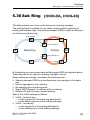
5.36 Sub Ring
353
5.37 PRP
358
5.38 PRP Configuration
360
5.39 DAN/VDAN Table
363
5.40 Proxy Node Table
364
5.41 Statistics
365
5.42 HSR
366
5.43 HSR Configuration
368
5.44 DAN/VDAN Table
374
5.45 Proxy Node Table
375
5.46 Statistics
376
5.47 Spanning Tree
377
5.48 Spanning Tree - Global
378
RM GUI HiOS-2S/2A/3S RSPE
Release 4.0 07/2014
7
Contents
5.49 Spanning Tree - Port
5.49.1 CIST
5.49.2 Guards
383
384
389
5.50 Link Aggregation
393
5.51 Link Backup
403
6
Routing
407
6.1
Routing Global
408
6.2
Interfaces
412
6.3
Configuration
6.3.1 Wizard
413
416
6.4
Secondary Interface addresses
419
6.5
ARP
420
6.6
ARP Global
421
6.7
ARP Current
424
6.8
ARP Static
6.8.1 Wizard
426
428
6.9
Router Discovery
430
6.10 Routing Table
432
6.11 Tracking
436
6.12 Tracking Configuration
437
6.13 Applications
442
6.14 L3 Relay
6.14.1 Create
443
446
6.15 Loopback Interface
448
6.16 Multicast Routing
450
6.17 Multicast Routing Global
6.17.1 Configuration
6.17.2 Statistics
451
452
454
6.18 Multicast Routing Boundary Configuration
456
6.19 Multicast Routing Static
459
8
RM GUI HiOS-2S/2A/3S RSPE
Release 4.0 07/2014
Contents
6.20 IGMP
462
6.21 IGMP Configuration
6.21.1 Port
6.21.2 Cache Information
6.21.3 Interface Membership
463
465
468
470
6.22 IGMP Proxy Configuration
471
6.23 IGMP Proxy Database
6.23.1 Groups
6.23.2 Source List
473
473
475
6.24 L3-Redundancy
476
6.25 VRRP/HiVRRP
477
6.26 VRRP/HiVRRP Configuration
6.26.1 Wizard
478
484
6.27 HiVRRP Domains
489
6.28 VRRP Statistics
491
6.29 Tracking
493
7
Diagnostics
7.1
Status Configuration
496
7.2
Device Status
7.2.1 Global
7.2.2 Port
7.2.3 Status
497
498
502
503
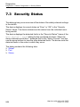
7.3
Security Status
7.3.1 Global
7.3.2 Port
7.3.3 Status
504
505
510
511
7.4
Signal Contact
512
7.5
Signal Contact 1
7.5.1 Global
7.5.2 Port
7.5.3 Status
513
514
519
520
7.6
MAC Notification
521
7.7
Alarms (Traps)
523
7.8
System
525
7.9
System Information
526
RM GUI HiOS-2S/2A/3S RSPE
Release 4.0 07/2014
495
9
Contents
7.10 Hardware State
527
7.11 Configuration Check
528
7.12 IP Address Conflict Detection
530
7.13 ARP Table
536
7.14 Selftest
537
7.15 Email Notification
540
7.16 Email Notification Global
541
7.17 Receiver
545
7.18 Mail Server
547
7.19 Syslog
549
7.20 Ports
551
7.21 SFP
552
7.22 TP cable diagnosis
553
7.23 Port Monitor
7.23.1 Global
7.23.2 Link Flap
7.23.3 CRC/Fragments
555
556
559
560
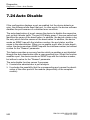
7.24 Auto Disable
562
7.25 Port Mirroring
566
7.26 LLDP
569
7.27 Configuration
570
7.28 Topology Discovery
7.28.1 LLDP
7.28.2 LLDP-MED
574
575
577
7.29 SFlow
579
7.30 SFlow Configuration
7.30.1 Global
7.30.2 Sampler
7.30.3 Poller
580
581
582
583
7.31 SFlow Receiver
584
7.32 Report
586
7.33 Global
587
7.34 Persistent Logging
592
10
RM GUI HiOS-2S/2A/3S RSPE
Release 4.0 07/2014
Contents
7.35 System Log
595
7.36 Audit Trail
596
8
Advanced
597
8.1
DHCP L2 Relay
598
8.2
DHCP L2 Relay Configuration
8.2.1 Interface
8.2.2 VLAN
599
600
601
8.3
DHCP L2 Relay Statistics
603
8.4
DHCP Server
604
8.5
DHCP Server Global
605
8.6
Pool
607
8.7
Lease Table
611
8.8
DNS
613
8.9
DNS Client
614
8.10 DNS Client Global
615
8.11 DNS Client Current
617
8.12 DNS Client Static
618
8.13 Static Hosts
620
8.14 Industrial Protocols
622
8.15 IEC61850-MMS
623
8.16 Command Line Interface
626
A
Appendix
A.1
Technical Data
628
A.2
List of RFCs
629
A.3
Underlying IEEE Standards
631
A.4
Underlying IEC Norms
632
A.5
Underlying ANSI Norms
633
A.6
Maintenance
634
A.7
Literature references
635
RM GUI HiOS-2S/2A/3S RSPE
Release 4.0 07/2014
627
11
Contents
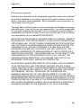
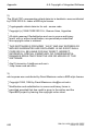
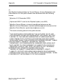
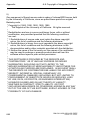
A.8
Copyright of Integrated Software
A.8.1 lighttpd
A.8.2 Expat
A.8.3 libcurl
A.8.4 libssh2
A.8.5 OpenSSH
A.8.6 OpenSSL
A.8.7 Parts of the FreeBSD IP stack
B
Index
655
C
Readers’ Comments
658
D
Further Support
661
12
636
636
637
638
639
640
650
653
RM GUI HiOS-2S/2A/3S RSPE
Release 4.0 07/2014
Safety instructions
Safety instructions
WARNING
UNCONTROLLED MACHINE ACTIONS
To avoid uncontrolled machine actions caused by data loss, configure all
the data transmission devices individually.
Before you start any machine which is controlled via data transmission, be
sure to complete the configuration of all data transmission devices.
Failure to follow these instructions can result in death, serious injury,
or equipment damage.
RM GUI HiOS-2S/2A/3S RSPE
Release 4.0 07/2014
13
Safety instructions
14
RM GUI HiOS-2S/2A/3S RSPE
Release 4.0 07/2014
About this Manual
About this Manual
The “GUI” reference manual contains detailed information on using the
graphical interface to operate the individual functions of the device.
The “Command Line Interface” reference manual contains detailed information on using the Command Line Interface to operate the individual functions
of the device.
The “Installation” user manual contains a device description, safety instructions, a description of the display, and the other information that you need to
install the device.
The “Basic Configuration” user manual contains the information you need to
start operating the device. It takes you step by step from the first startup operation through to the basic settings for operation in your environment.
The “Redundancy Configuration” user manual document contains the information you require to select the suitable redundancy procedure and
configure it.
The “Routing Configuration User Manual” document contains the information
you need to start operating the routing function. It takes you step-by-step
from a small router application through to the router configuration of a
complex network.
The manual enables you to configure your router by following the examples.
The document “HiView User Manual” contains information about the GUI
application HiView. This application offers you the possibility to use the
graphical user interface without other applications such as a Web browser or
an installed Java Runtime Environment (JRE).
RM GUI HiOS-2S/2A/3S RSPE
Release 4.0 07/2014
15
About this Manual
The Industrial HiVision network management software provides you with
additional options for smooth configuration and monitoring:
ActiveX control for SCADA integration
Auto-topology discovery
Browser interface
Client/server structure
Event handling
Event log
Simultaneous configuration of multiple devices
Graphical user interface with network layout
SNMP/OPC gateway
16
RM GUI HiOS-2S/2A/3S RSPE
Release 4.0 07/2014
Key
Key
The designations used in this manual have the following meanings:
List
Work step
Subheading
Link
Note:
Cross-reference with link
A note emphasizes an important fact or draws your attention to a dependency.
Courier
ASCII representation in the graphical user interface
RM GUI HiOS-2S/2A/3S RSPE
Release 4.0 07/2014
17
Key
18
RM GUI HiOS-2S/2A/3S RSPE
Release 4.0 07/2014
Graphical User Interface
Graphical User Interface
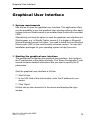
System requirements
Use HiView to open the graphical user interface. This application offers
you the possibility to use the graphical user interface without other applications such as a Web browser or an installed Java Runtime Environment
(JRE).
Alternatively you have the option to open the graphical user interface in a
Web browser, e.g. in Mozilla Firefox version 3.5 or higher or Microsoft
Internet Explorer version 6 or higher. You need to install the Java Runtime
Environment (JRE) in the most recently released version. You can find
installation packages for your operating system at http://java.com.
Starting the graphical user interface
The prerequisite for starting the graphical user interface, first configure
the IP parameters of the device correctly. The “Basic Configuration” user
manual contains detailed information that you need to specify the IP
parameters.
Start the graphical user interface in HiView:
Start HiView.
In the URL field of the start window, enter the IP address of your
device.
Click "Open".
HiView sets up the connection to the device and displays the login
window.
RM GUI HiOS-2S/2A/3S RSPE
Release 4.0 07/2014
19
Graphical User Interface
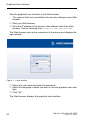
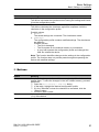
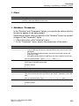
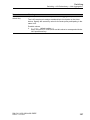
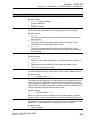
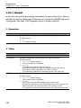
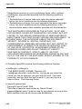
Start the graphical user interface in the Web browser:
– This requires that Java is enabled in the security settings of your Web
browser.
Start your Web browser.
Write the IP address of the device in the address field of the Web
browser. Use the following form: https://xxx.xxx.xxx.xxx
The Web browser sets up the connection to the device and displays the
login window.
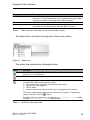
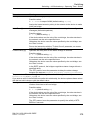
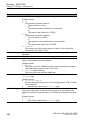
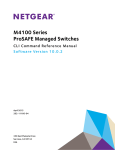
Figure 1: Login window
Select the user name and enter the password.
Select the language in which you want to use the graphical user interface.
Click "Ok".
The Web browser displays the graphical user interface.
20
RM GUI HiOS-2S/2A/3S RSPE
Release 4.0 07/2014
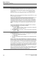
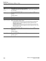
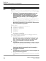
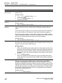
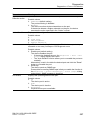
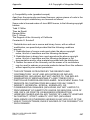
Graphical User Interface
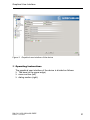
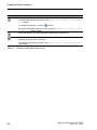
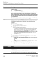
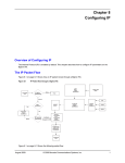
Figure 2: Graphical user interface of the device
Operating Instructions
The graphical user interface of the device is divided as follows:
Tab area (at the upper edge)
menu section (left)
dialog section (right).
RM GUI HiOS-2S/2A/3S RSPE
Release 4.0 07/2014
21
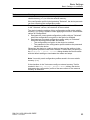
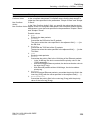
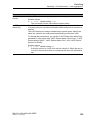
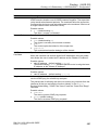
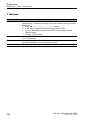
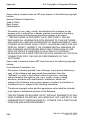
Graphical User Interface
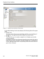
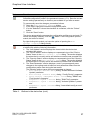
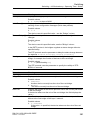
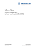
Figure 3: Graphical user interface of the device
In the default setting, the tab area displays the following tabs at the upper
edge.
"Online" tab
This tab contains the menus and dialogs with the current settings of
the device. You right-click the tab to open the context menu.
"+" tab
This tab allows you to create a snapshot or to display a previously
created snapshot.
A snapshot contains the settings and operating parameters the device
had at a given time in the past. The device allows you to compare the
current operating status with the operating status the device had at a
given time in the past.
22
RM GUI HiOS-2S/2A/3S RSPE
Release 4.0 07/2014
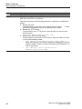
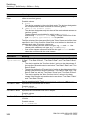
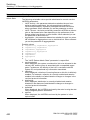
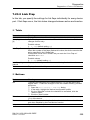
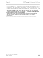
Graphical User Interface
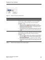
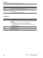
Figure 4: “Online” tab with context menu
Designation
Snapshot
Meaning
Create
Load …
The device generates a snapshot of the current settings. This
will take 20 s or longer, depending on the device settings.
In the tab area at the upper edge, the device adds the
"Snapshot …" tab.
While the device is generating the snapshot, the tab
displays the symbol
. The menu section and the dialog
section are concealed meanwhile. To continue to work,
change back to the "Online" tab.
If the snapshot is entirely generated, the symbol on the tab
disappears. The menu section and the dialog section are
visible.
The device loads a previously generated snapshot from a file.
This will take 10 s or longer, depending on the device settings.
In the tab area at the upper edge, the device adds the
"Snapshot …" tab.
While the device is loading the snapshot, the tab displays
the symbol
. The menu section and the dialog section
are concealed meanwhile. To continue to work, change
back to the "Online" tab.
If the snapshot is entirely generated, the symbol on the tab
disappears. The menu section and the dialog section are
visible.
Table 1:
“Online” tab: functions in the context menu
RM GUI HiOS-2S/2A/3S RSPE
Release 4.0 07/2014
23
Graphical User Interface
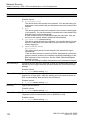
The "Snapshot …" tab displays the values in the usual way in the dialog
fields. The fields are write-protected, thus modifying the values is impossible. You right-click the tab to open the context menu.
Designation
Save As...
Close
Table 2:
Meaning
Exports the snapshot and saves the settings and operating parameters as a file on your PC.
Closes the "Snapshot …" tab. Unsaved information are lost.
“Snapshot” tab: functions in the context menu
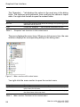
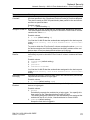
The menu displays the menu items. When you click a menu item, the user
interface displays the corresponding dialog in the dialog area.
Figure 5: Menu section with context menu
You right-click the menu section to open the context menu.
Designation
Expand All
Collapse All
Table 3:
24
Meaning
Expands the nodes in the menu tree. The menu section displays the
menu items for all levels.
Collapses the nodes in the menu tree. The menu section displays
the menu items for the top level.
Menu section: Functions in the context menu
RM GUI HiOS-2S/2A/3S RSPE
Release 4.0 07/2014
Graphical User Interface
Designation
Expand Node
Meaning
Expands the selected node and collapses the other nodes in the
menu tree. This function allows you to expand a main node without
scrolling and without collapsing other nodes manually.
Allows you to quickly jump back to a previously selected menu item.
Allows you to quickly jump forward to a previously selected menu
item when you have previously used the "Back" function.
Back
Forward
Table 3:
Menu section: Functions in the context menu (cont.)
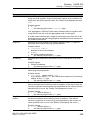
The status line is located in the top part of the menu section.
Figure 6: Status line
The status line contains the following buttons:
Button
Function
Refreshes the status line. The buttons display the values loaded from the volatile
memory (RAM) of the device.
Terminates the refreshing of the status line.
When you position the mouse pointer over the button, the user interface opens
a bubble help with the following information:
The time at which the device last refreshed the values
Name of the user logged in
Device name
Network protocol by means of which you are logged in to the device.
The device automatically refreshes the values once a minute. To refresh the
display manually, click the
button.
By right-clicking this symbol you can open the Basic Settings > System dialog
and the Basic Settings > Network dialog directly.
Table 4:
Buttons in the status line
RM GUI HiOS-2S/2A/3S RSPE
Release 4.0 07/2014
25
Graphical User Interface
Button
Function
When you position the mouse pointer over the button, the user interface opens
a bubble help with the summary of the Diagnostics > System > Configuration
Check dialog.
To refresh the display, click the
button.
By right-clicking this symbol you can open the Diagnostics > System > Config-
uration Check dialog directly.
Ends the session and terminates the connection to the device.
Displays the time in seconds after which the device automatically ends the
session when the user is inactive.
You specify the timeout period in the Device Security > Management Access >
Web dialog.
Table 4:
26
Buttons in the status line (cont.)
RM GUI HiOS-2S/2A/3S RSPE
Release 4.0 07/2014
Graphical User Interface
Button
Function
Displays that the configuration profile in the volatile memory (RAM) differs from the
Selected configuration profile in the permanent memory (NVM). Save the current
device settings permanently so that they are available to you after a restart.
To permanently save the changes, proceed as follows:
Open the Basic Settings > Load/Save dialog.
In the table, highlight the desired configuration profile.
If in the "Selected" column the checkbox is unmarked, click the "Select"
button.
Click the "Save" button.
The device automatically compares the configuration profiles once a minute. To
refresh the display manually, click the
button. If the configuration profiles
match, the button is hidden.
By right-clicking this symbol you have the option of opening the Basic
Settings > Load/Save dialog directly.
When you position the mouse pointer over the button, the user interface opens
a bubble help with the following information:
The "Last Update" section displays the time at which the device last
refreshed the values.
The "Device Status" section displays a compressed view of the "Device
Status" frame in the Basic Settings > System dialog. The section displays
the alarm that is currently active and whose occurrence was recorded first.
The "Security Status" section displays a compressed view of the "Security
Status" frame in the Basic Settings > System dialog. The section displays
the alarm that is currently active and whose occurrence was recorded first.
The "Boot Parameter" section displays a note if you permanently save
changes to the settings and at least one boot parameter differs from the
configuration profile used during the last restart.
The following settings cause the boot parameters to change:
– Basic Settings > External Memory dialog, "Enable Automatic Software
Update" parameter
– Basic Settings > External Memory dialog, "Config Priority" parameter
– Device Security > Management Access > Server dialog, "SNMP" tab,
"Port Number" parameter
– Diagnostics > System > Selftest dialog, "RAM Test" parameter
– Diagnostics > System > Selftest dialog, "Activate SysMon1" parameter
– Diagnostics > System > Selftest dialog, "Load default config on error"
parameter
Table 4:
Buttons in the status line (cont.)
RM GUI HiOS-2S/2A/3S RSPE
Release 4.0 07/2014
27
Graphical User Interface
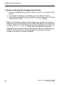
Notes on Saving the Configuration Profile
To copy changed settings to the volatile memory (RAM), click the "Set"
button.
To refresh the display in the dialogs, click the "Reload" button.
To keep the changed settings even after restarting the device, click the
"Save" button in the Basic Settings > Load/Save dialog.
Note: Unintentional changes to the settings may cause the connection
between your PC and the device to be terminated. Before you change the
settings, enable the "Undo Modifications of Configuration" function in the
Basic Settings > Load/Save dialog. With this function, the device
restores the active configuration profile saved in the non-volatile memory
(NVM) if the connection is interrupted after the settings have been
changed. The device remains reachable.
28
RM GUI HiOS-2S/2A/3S RSPE
Release 4.0 07/2014
Basic Settings
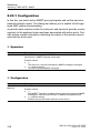
1 Basic Settings
With this menu you can configure the basic settings of the device.
The menu contains the following dialogs:
System
Network
Software
Load/Save
External Memory
Port
Power over Ethernet
Restart
RM GUI HiOS-2S/2A/3S RSPE
Release 4.0 07/2014
29
Basic Settings
Basic Settings > System
1.1 System
Basic Settings > System
With this dialog you can display device properties and monitor individual
operating statuses.
Device Status
The fields in this frame display the device status and inform you about
alarms that have occurred. You specify the parameters that the device
monitors in the Diagnostics > Status Configuration > Device Status
dialog.
Parameters
Symbol
Alarm Counter
Alarm Reason
Meaning
Displays the device status.
Possible values:
The device status is OK. The monitored parameters have the
desired status.
An alarm has occurred. At least one monitored parameter differs
from the desired status.
Displays the number of current alarms.
Displays the cause of the alarm and the time at which the device triggered
the alarm. If the "Alarm Counter" displays more than 1 alarm, use the
arrow buttons to call up the other alarm states.
Possible values:
Cause of the event (Date and time in the format Month, Day, Year
hh:mm:ss AM/PM).
The device triggers an alarm if a monitored parameter differs from the
desired status. In the Diagnostics > Status Configuration > Device
Status dialog the parameters are sorted by priority: High priority at the top,
low priority at the bottom.
Note: The device reports an alarm if you connect one power supply unit
exclusively for the supply voltage to a device with multiple ports. To avoid
this alarm, you deactivate the monitoring of the missing power supply
units in the Diagnostics > Status Configuration > Device Status
dialog.
30
RM GUI HiOS-2S/2A/3S RSPE
Release 4.0 07/2014
Basic Settings
Basic Settings > System
Security Status
The fields in this frame display the security status and inform you about
alarms that have occurred. You specify the parameters that the device
monitors in the Diagnostics > Status Configuration > Security
Status dialog.
Parameters
Symbol
Alarm Counter
Alarm Reason
Meaning
Displays the security status.
Possible values:
The device status is OK. The monitored parameters have the
desired status.
An alarm has occurred. At least one monitored parameter differs
from the desired status.
Displays the number of current alarms.
Displays the cause of the alarm and the time at which the device triggered
the alarm. If the "Alarm Counter" displays more than 1 alarm, use the
arrow buttons to call up the other alarm states.
Possible values:
Cause of the event (Date and time in the format Month, Day, Year
hh:mm:ss AM/PM).
The device triggers an alarm if a monitored parameter differs from the
desired status. In the Diagnostics > Status Configuration > Security
Status dialog the parameters are sorted by priority: High priority at the top,
low priority at the bottom.
Signal Contact Status
The fields in this frame display the security status and inform you about
alarms that have occurred. You specify the parameters that the device
monitors in the Diagnostics > Status Configuration > Signal
Contact dialog.
Parameters
Symbol
Meaning
Displays the security status.
Possible values:
The device status is OK. The monitored parameters have the
desired status.
An alarm has occurred. At least one monitored parameter differs
from the desired status.
RM GUI HiOS-2S/2A/3S RSPE
Release 4.0 07/2014
31
Basic Settings
Basic Settings > System
Parameters
Alarm Counter
Alarm Reason
Meaning
Displays the number of current alarms.
Displays the cause of the alarm and the time at which the device triggered
the alarm. If the "Alarm Counter" displays more than 1 alarm, use the
arrow buttons to call up the other alarm states.
Possible values:
Cause of the event (Date and time in the format Month, Day, Year
hh:mm:ss AM/PM).
The device triggers an alarm if a monitored parameter differs from the
desired status. In the Diagnostics > Status Configuration > Signal
Contact dialog the parameters are sorted by priority: High priority at the
top, low priority at the bottom.
System Data
The fields in this frame display operating data and information on the location of the device.
Parameters
Name
Meaning
Specifies the device name.
Location
Possible values:
Alphanumeric ASCII character string with 0..255 characters
Specifies the location of the device.
Contact
Possible values:
Alphanumeric ASCII character string with 0..255 characters
Specifies the contact person for this device.
Device Type
Possible values:
Alphanumeric ASCII character string with 0..255 characters
Displays the product name of the basic device.
32
RM GUI HiOS-2S/2A/3S RSPE
Release 4.0 07/2014
Basic Settings
Basic Settings > System
Parameters
Module {0}
Meaning
Displays the product name of the inserted module.
The device offers you the possibility of inserting or removing the
modules on-the-fly during operation. If you remove a module, the
module settings in the device are saved and are still available even
after a reboot.
– If you replace the module with an identical module, the device
applies the settings to the new module immediately.
– If you replace the module with a different type of module, the
module remains inoperative until reboot of the device. The
power LED on the module flashes 3 times per second. After the
reboot, the device applies the factory settings to the new
module.
The checkbox displays the operation state of the module. It gives
you the option to delete the module settings.
Power Supply {0}
Possible values:
marked (grayed out)
The module is plugged in and ready for use.
marked
The module has been removed.
The module settings are stored in the device.
unmarked
The module has been removed.
The settings of the module are deleted.
Displays the status of the power supply unit on the relevant voltage
supply connection.
Possible values:
present
not present
defective
RM GUI HiOS-2S/2A/3S RSPE
Release 4.0 07/2014
33
Basic Settings
Basic Settings > System
Parameters
Uptime
Temperature (°C)
Meaning
Displays the time that has elapsed since this device was last
restarted.
Possible values:
Time in the format day(s), hh:mm:ss
The middle field displays the current temperature in the device in
°C.
This field specifies the lower temperature threshold in °C.
If the temperature in the device falls below this value, the
device generates an alarm.
This field specifies the upper temperature threshold in °C.
If the temperature in the device exceeds this value, the
device generates an alarm.
Possible values:
-99..99 (integer)
You activate the monitoring of the temperature thresholds in the
Diagnostics > Status Configuration > Device Status dialog.
The “Installation” user manual contains detailed information about
setting the temperature thresholds.
Device View
The image in this frame displays a simplified version of the structure of the
device and its equipment with modules.
34
RM GUI HiOS-2S/2A/3S RSPE
Release 4.0 07/2014
Basic Settings
Basic Settings > System
The image also displays the states of the device status LEDs and the
ports at the time of the last update.
The following symbols represent the status of the individual ports. In some
situations, these symbols interfere with one another. If you position the
mouse pointer over the port icon, a bubble help displays a detailed
description of the port state.
Criterion
Bandwidth of the
device port
Symbol
10 Mbit/s
Port activated, connection okay, full-duplex mode
100 Mbit/s
Port activated, connection okay, full-duplex mode
Operating state
1000 Mbit/s
Port activated, connection okay, full-duplex mode
Half-duplex mode activated
See the Basic Settings > Port dialog, "Configuration" tab,
"Automatic Configuration" checkbox, "Manual Configuration"
field and "Manual Cable Crossing (Auto. Conf. off)" field.
Autonegotiation activated
See the Basic Settings > Port dialog, "Configuration" tab,
"Automatic Configuration" checkbox.
Port is blocked by a redundancy function.
AdminLink
Port is deactivated, connection okay
Port is deactivated, no connection set up
See the Basic Settings > Port dialog, "Configuration" tab,
"Port on" checkbox, and "Link/ Current Settings" field.
Reloading
The graphical user interface automatically updates the display of the
dialog every 100 seconds. In the process, it updates the fields and
symbols with the values that are saved in the volatile memory (RAM) of the
device. At the bottom left of the dialog, you will find the time of the next
update.
Figure 7: Time to next Reload
RM GUI HiOS-2S/2A/3S RSPE
Release 4.0 07/2014
35
Basic Settings
Basic Settings > System
Note: The graphical user interface uses this function to update the display
in the Basic Settings > System dialog.
Buttons
Button
Set
Reload
Help
36
Meaning
Transfers the changes to the volatile memory (RAM) of the device and
applies them. To save the changes in the non-volatile memory, proceed
as follows:
Open the Basic Settings > Load/Save dialog.
In the table, highlight the desired configuration profile.
If in the "Selected" column the checkbox is unmarked, click the
"Select" button.
Click the "Save" button.
Updates the fields with the values that are saved in the volatile memory
(RAM) of the device.
Opens the online help.
RM GUI HiOS-2S/2A/3S RSPE
Release 4.0 07/2014
Basic Settings
Basic Settings > Network
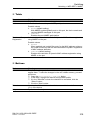
1.2 Network
Basic Settings > Network
This dialog allows you to specify the IP, VLAN and HiDiscovery settings
required for the access to the device management through the network.
Management Interface
This frame allows you to specify the following settings:
The source from which the device management receives its IP parameters
VLAN in which the management can be accessed
Parameters
Meaning
IP Address Assign- Specifies the source from which the device receives its IP parameters
ment
after starting:
Possible values:
BOOTP
The device receives its IP parameters from a BOOTP or DHCP server.
The server evaluates the MAC address of the device, then assigns the
IP parameters.
DHCP (default setting)
The device receives its IP parameters from a DHCP server.
The server evaluates the MAC address, the DHCP name, or other
parameters of the device, then assigns the IP parameters.
Local
The device uses the IP parameters from the internal memory. You
specify the settings for this in the "IP Parameter" frame.
Note: If there is no response from the BOOTP or DHCP server, the device
sets the IP address to 0.0.0.0 and makes another attempt to obtain a valid
IP address.
RM GUI HiOS-2S/2A/3S RSPE
Release 4.0 07/2014
37
Basic Settings
Basic Settings > Network
Parameters
VLAN ID
Meaning
Specifies the ID of the VLAN in which the device management is accessible through the network.
Possible values:
1..4042 (default setting: 1)
MAC Address
You access the device management through device ports that are
members of this VLAN.
You specify which VLAN a certain device port is assigned to in the
Switching > VLAN > Configuration dialog.
Displays the MAC address of the device. The device management can be
accessed via the network using the MAC address.
HiDiscovery Protocol
This frame allows you to specify settings for the access to the device
using the HiDiscovery protocol.
On a PC the HiDiscovery software displays you the Hirschmann devices
in the network that can be accessed on which the HiDiscovery function is
switched on. You can access these devices even if they have invalid IP
parameters or none at all. The HiDiscovery software allows you to change
the IP parameters in the device.
Parameters
Operation
Meaning
Activates/deactivates the HiDiscovery function in the device.
Possible values:
On (default setting)
HiDiscovery is activated.
You can use the HiDiscovery software to access the device from your
PC.
Off
HiDiscovery is deactivated.
38
RM GUI HiOS-2S/2A/3S RSPE
Release 4.0 07/2014
Basic Settings
Basic Settings > Network
Parameters
Access
Meaning
Activates/deactivates the write access to the device using HiDiscovery.
Possible values:
readWrite (default setting)
The HiDiscovery software is given write access to the device.
With this setting you can change the IP parameters in the device.
readOnly
The HiDiscovery software is given read-only access to the device.
With this setting you can view the IP parameters in the device.
Signal
Recommendation: Change the setting to readOnly exclusively after
putting the device into operation.
Activates/deactivates the flashing of the port LEDs as does the function of
the same name in the HiDiscovery software. The function allows you to
identify the device in the field.
Possible values:
unmarked (default setting)
The flashing of the port LEDs is inactive.
marked
The flashing of the port LEDs is active.
The port LEDs flash until you disable the function again.
Note: With the HiDiscovery software you access the device through
device ports that are members of the same VLAN as the device management exclusively. You specify which VLAN a certain device port is
assigned to in the Switching > VLAN > Configuration dialog.
BOOTP/ DHCP
Parameters
Client ID
Meaning
Displays the DHCP client ID that the device sends to the BOOTP or DHCP
server. If the server is configured accordingly, it reserves an IP address for
this DHCP client ID. Therefore, the device receives the same IP from the
server every time it requests it.
The DHCP client ID that the device sends is the device name specified in
the "Name" field in the Basic Settings > System dialog.
RM GUI HiOS-2S/2A/3S RSPE
Release 4.0 07/2014
39
Basic Settings
Basic Settings > Network
IP Parameter
This frame allows you to assign the IP parameters manually. These fields
can be edited if you have selected the value Local in the "Management
Interface" frame, "IP Address Assignment" field.
Parameters
IP Address
Netmask
Gateway address
Meaning
Specifies the IP address under which the device management can be
accessed through the network.
Possible values:
Valid IPv4 address
(default setting: —)
Specifies the netmask.
The netmask identifies the network prefix and the host address of the
device in the IP address.
Possible values:
Valid IPv4 netmask
(default setting: —)
Specifies the IP address of a router through which the device accesses
other devices outside its own network.
Possible values:
Valid IPv4 address
(default setting: —)
Buttons
Button
Set
Reload
Help
40
Meaning
Transfers the changes to the volatile memory (RAM) of the device and
applies them. To save the changes in the non-volatile memory, proceed
as follows:
Open the Basic Settings > Load/Save dialog.
In the table, highlight the desired configuration profile.
If in the "Selected" column the checkbox is unmarked, click the
"Select" button.
Click the "Save" button.
Updates the fields with the values that are saved in the volatile memory
(RAM) of the device.
Opens the online help.
RM GUI HiOS-2S/2A/3S RSPE
Release 4.0 07/2014
Basic Settings
Basic Settings > Software
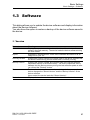
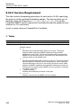
1.3 Software
Basic Settings > Software
This dialog allows you to update the device software and display information
about the device software.
You also have the option to restore a backup of the device software saved in
the device.
Version
Parameters
Stored Version
Export
Running Version
Backup Version
Restore
Bootcode
Meaning
Displays the version number and creation date of the device software
stored in the flash memory. The device loads the device software during
the next restart.
Exports the "Stored Version" of the device software and saves it as an
image file on your PC.
Displays the version number and creation date of the device software that
the device loaded during the last restart and is currently running.
Displays the version number and creation date of the device software
saved as a backup in the flash memory. The device copied this device
software into the backup memory during the last software update or after
you clicked the "Restore" button.
Restores the device software saved as a backup. In the process, the
device changes the "Stored Version" and the "Backup Version" of the
device software.
Upon restart, the device loads the "Stored Version".
Displays the version number and creation date of the boot code.
RM GUI HiOS-2S/2A/3S RSPE
Release 4.0 07/2014
41
Basic Settings
Basic Settings > Software
Software Update
Parameters
File
…
Update
Meaning
Specifies the path and the file name of the image file with which you
update the device software.
The device gives you the following options for updating the device software:
Software update from the PC
If the file is located on your PC or on a network drive, click the " … "
button and select the file there.
Software update from a TFTP server
If the file is located on a TFTP server, enter the URL for the file in the
following form:
tftp://<IP address>/<path>/<file name>
Software update from an SCP or SFTP server
If the file is located on an SCP or SFTP server, enter the URL for the
file in one of the following forms:
– scp:// or sftp://<IP address>/<path>/<file name>
When you click the "Update" button, the device displays the
"Authentication" window. There you enter "Username" and "Password", to login to the server.
– scp:// or sftp://<user>:<password>@<IP
address>/<path>/<file name>
Displays the "Open" dialog. If the image file is located on your PC or on a
network drive, you select the image file here.
Updates the device software
The device installs the selected file in the flash memory, replacing the
previously saved device software. Upon restart, the device loads the
installed device software.
The device copies the existing software into the backup memory.
To remain logged in to the device during the software update, move the
mouse pointer occasionally. Alternatively, specify a sufficiently high value
in the Device Security > Management Access > Web dialog, field "Web
Interface Session Timeout [min]" before the software update.
Alternatively, the device allows you to update the device software by rightclicking in the table if the image file is located in the external memory.
42
RM GUI HiOS-2S/2A/3S RSPE
Release 4.0 07/2014
Basic Settings
Basic Settings > Software
Table
Parameters
File Location
Index
File name
Firmware
Applet
Logic
Meaning
Displays the storage location of the device software.
Possible values:
RAM
Volatile memory of the device
FLASH
Non-volatile memory (NVM) of the device
SD CARD
External SD memory (ACA31)
USB
External USB memory (ACA21)
Displays the index of the device software.
For the device software in the flash memory, the index has the following
meaning:
1
Upon restart, the device loads this device software.
2
The device copied this device software into the backup area during the
last software update.
Displays the device-internal file name of the device software.
Displays the version number and creation date of the device software.
Displays the version number of the graphical user interface (GUI).
Displays the version number of the logic module for devices with programmable hardware (FPGA).
Buttons
Button
Reload
Help
Meaning
Updates the fields with the values that are saved in the volatile memory
(RAM) of the device.
Opens the online help.
RM GUI HiOS-2S/2A/3S RSPE
Release 4.0 07/2014
43
Basic Settings
Basic Settings > Load/Save
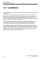
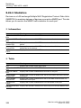
1.4 Load/Save
Basic Settings > Load/Save
This dialog allows you to save the device settings permanently in a configuration profile.
The device can hold several configuration profiles. When you activate an
alternative configuration profile, you change to other device settings. You
have the option of exporting the configuration profiles to your PC or to a
server. Vice versa you have the option of importing the configuration profiles
from your PC or from a server to the device.
In the default setting, the device saves the configuration profiles unencrypted. When you enter in the frame a password, the device saves the
current and the afterwards created configuration profiles encrypted.
Unintentional changes to the settings may cause the connection between
your PC and the device to be terminated. To maintain the device accessible,
enable the "Undo Modifications of Configuration" function before changing
settings. If the connection terminates, the device loads the configuration
profile saved in the non-volatile memory (NVM).
44
RM GUI HiOS-2S/2A/3S RSPE
Release 4.0 07/2014
Basic Settings
Basic Settings > Load/Save
External Memory
Parameters
Selected external
memory
Status
Meaning
Specifies the external memory that the device uses for file operations. On
this external memory, the device stores items including copies of the
device software.
Possible values:
SD
External SD memory (ACA31).
USB
External USB memory (ACA21).
Displays the operating state of the external memory.
Possible values:
notPresent
No external memory connected.
removed
Someone has removed the external memory from the device during
operation.
ok
The external memory is connected and ready for operation.
outOfMemory
The memory space is occupied on the external memory.
genericErr
The device has detected an error.
Configuration Encryption
Parameters
Active
Meaning
Displays whether the configuration encryption is switched on in the device.
Possible values:
unmarked
The configuration encryption is switched off.
The device loads a configuration profile from the non-volatile memory
solely (NVM) if it is unencrypted.
marked
The configuration encryption is switched on.
The device loads a configuration profile from the non-volatile memory
(NVM) if it is encrypted and the password matches the password stored
in the device.
If the "Config Priority" field has the value first or second and the configuration profile is unencrypted, the "Security Status" frame in the Basic
Settings > System dialog displays an alarm.
In the Diagnostics > Status Configuration > Security Status dialog,
"Global" tab, "Monitor" column you specify whether the device monitors
the "Load unencrypted config from external memory" parameter.
RM GUI HiOS-2S/2A/3S RSPE
Release 4.0 07/2014
45
Basic Settings
Basic Settings > Load/Save
Parameters
Set Password
Meaning
Encrypts configuration profiles and uses a password to make unauthorized access more difficult.
Enter the new password in the "Set Password" dialog.
When you are changing an existing password, also enter the existing
password.
Mark the "Save Configuration afterwards" checkbox to use encryption
also for the Selected configuration profile in the non-volatile memory
(NVM) and in the external memory.
Note: Use this function solely if a maximum of 1 configuration profile is
stored in the non-volatile memory (NVM) of the device. Before creating
additional configuration profiles, decide for or against permanently activated configuration encryption in the device. Save additional configuration
profiles either unencrypted or encrypted with the same password.
If you are replacing a device with an encrypted configuration profile, e.g.
due to a defect, you proceed as follows:
Restart the new device and assign the IP parameters.
Open the Basic Settings > Load/Save dialog on the new device.
Encrypt the configuration profile in the new device - see above. Enter
the same password you used in the defective device.
Install the external memory from the defective device in the new
device.
Restart the new device.
When it is restarted, the device loads the configuration profile with the
settings of the defective device from the external memory. The device
copies the settings into the volatile memory (RAM) and into the nonvolatile memory (NVM).
Note: The prerequisite for loading a configuration profile from the external
memory is that the "Config Priority" field in the Basic Settings > External
Memory dialog displays the value first or second.
This value is set as the default setting.
Delete
Cancels the configuration encryption in the device.
Enter the existing password in the "Delete" dialog.
Mark the "Save Configuration afterwards" checkbox to remove the
encryption also for the Selected configuration profile in the non-volatile memory (NVM) and in the external memory.
Note: If you keep additional encrypted configuration profiles in the
memory, the device prevents you from activating or designating these
configuration profiles as Selected.
46
RM GUI HiOS-2S/2A/3S RSPE
Release 4.0 07/2014
Basic Settings
Basic Settings > Load/Save
Information
Parameters
NVM in sync with
running config
Meaning
Displays whether the configuration profile in the volatile memory (RAM) and
the Selected configuration profile in the non-volatile memory (NVM) are the
same.
Possible values:
marked
The configuration profiles are the same.
unmarked
The configuration profiles differ. The device saves changes temporarily if, for example, you click on "Set" in a dialog while the device is
operating.
External memory in Displays whether the Selected configuration profile in the external
sync with NVM
memory and the Selected configuration profile in the non-volatile memory
(NVM) are the same.
Possible values:
marked
The configuration profiles are the same.
unmarked
The configuration profiles differ.
Possible causes:
– No external memory is connected to the device.
– In the Basic Settings > External Memory dialog, the "Auto-save
config on external memory" function is switched off.
RM GUI HiOS-2S/2A/3S RSPE
Release 4.0 07/2014
47
Basic Settings
Basic Settings > Load/Save
Undo Modifications of Configuration
Parameters
Operation
Meaning
When a user switches on the function, the device continuously checks
whether it can still be reached from the IP address of the user. If the
connection is lost, after a specified time period the device loads the
"Selected" configuration profile from the non-volatile memory (NVM). Afterwards, the device can be accessed again.
Possible values:
On
Function is switched on:
– You specify the time period between the loss of the connection
and the loading of the configuration profile in the field "Period to
undo while Connection is lost [s]".
– If the non-volatile memory (NVM) contains multiple configuration
profiles, the device loads the configuration profile designated as
"Selected".
Off (default setting)
Function is switched off.
Switch the function off again before you close the graphical user interface. You thus prevent the device from restoring the configuration
profile designated as "Selected".
Note: Before you switch on the function, save the settings in the configuration profile. Current changes, that are saved temporarily, are therefore
maintained in the device.
Period to undo while Specifies the time in seconds after which the device loads the "Selected"
Connection is lost configuration profile from the non-volatile memory (NVM) if the connection
[s]
is lost.
Possible values:
30..600 (default setting 600)
Watchdog IP
Address
Specify a sufficiently large value. Take into account the time when you are
viewing the dialogs of the graphical user interface without changing or
updating them.
Displays the IP address of the PC on which you have activated the function.
Possible values:
IPv4 address (default setting: 0.0.0.0)
48
RM GUI HiOS-2S/2A/3S RSPE
Release 4.0 07/2014
Basic Settings
Basic Settings > Load/Save
Table
Parameters
Storage Type
Meaning
Displays the storage location of the configuration profile.
Name
Possible values:
RAM (volatile memory of the device)
In the volatile memory, the device stores the settings for the current
operation.
NVM (non-volatile memory of the device)
From the non-volatile memory, the device loads the Selected configuration profile during a restart or when applying the function "Undo
Modifications of Configuration".
The non-volatile memory provides space for multiple configuration
profiles, depending on the number of settings saved in the configuration profile.
The device manages a maximum of 20 configuration profiles in the
non-volatile memory.
If you highlight a configuration profile in the table and click "Activate",
the device loads this configuration profile into the volatile memory
(RAM).
ENVM (external memory)
On the external memory, the device saves a backup copy of the
Selected configuration profile.
The prerequisite is that in the Basic Settings > External Memory
dialog you mark the "Auto-save config on external memory" checkbox.
Displays the name of the configuration profile.
Modification Date
(UTC)
Possible values:
running-config
Name of the configuration profile in the volatile memory (RAM).
config
Name of the factory setting configuration profile in the non-volatile
memory (NVM).
User-defined name
The device allows you to save a configuration profile with a userdefined name by highlighting an existing configuration profile in the
table and clicking the "Save As..." button.
Displays the time (UTC) at which a user last saved the configuration
profile.
RM GUI HiOS-2S/2A/3S RSPE
Release 4.0 07/2014
49
Basic Settings
Basic Settings > Load/Save
Parameters
Selected
Meaning
Displays whether the configuration profile is designated as Selected.
Possible values:
marked
The configuration profile is designated as Selected.
– The device loads the configuration profile into the volatile memory
RAM during a restart or when applying the function "Undo Modifications of Configuration".
– When you click "Save", the device saves the temporarily saved
settings in this configuration profile.
unmarked
Another configuration profile is designated as Selected.
Encrypted
To designate another configuration profile as Selected, you highlight the
desired configuration profile in the table and click "Activate".
Displays whether the configuration profile is encrypted.
Possible values:
marked
The configuration profile is encrypted.
unmarked
The configuration profile is unencrypted.
You activate/deactivate the encryption of the configuration profile in the
"Configuration Encryption" frame.
Encryption Verified Displays whether the password of the encrypted configuration profile
matches the password stored in the device.
Software Version
50
Possible values:
marked
The passwords match. The device is able to unencrypt the configuration profile.
unmarked
The passwords are different. The device is unable to unencrypt the
configuration profile.
Displays the version number of the device software that the device ran
when it saved the configuration profile.
RM GUI HiOS-2S/2A/3S RSPE
Release 4.0 07/2014
Basic Settings
Basic Settings > Load/Save
Parameters
Fingerprint
Meaning
Displays the checksum saved in the configuration profile.
The device calculates the checksum when saving the settings and inserts
it into the configuration profile.
Fingerprint Verified Displays whether the checksum in the configuration profile is valid.
The device calculates the checksum again and compares it with the
checksum in the configuration profile.
Possible values:
marked
The saved settings are consistent. The checksums match.
unmarked
The configuration profile contains modified settings. The checksums
are different.
Possible causes:
– The file is damaged.
– The file system on the external memory is inconsistent.
– A user has exported the configuration profile and changed the
XML file outside the device.
Note: This function identifies changes to the settings in the configuration
profile. The function does not provide protection against operating the
device with modified settings.
Buttons
Button
Set
Reload
Meaning
Transfers the changes to the volatile memory (RAM) of the device and
applies them. To save the changes in the non-volatile memory, proceed
as follows:
Open the Basic Settings > Load/Save dialog.
In the table, highlight the desired configuration profile.
If in the "Selected" column the checkbox is unmarked, click the
"Select" button.
Click the "Save" button.
Updates the fields with the values that are saved in the volatile memory
(RAM) of the device.
RM GUI HiOS-2S/2A/3S RSPE
Release 4.0 07/2014
51
Basic Settings
Basic Settings > Load/Save
Button
Save
Meaning
Transfers the settings from the volatile memory (RAM) into the configuration profile designated as “Selected” in the non-volatile memory (NVM).
If the checkbox in the "Auto-save config on external memory" field is
marked in the Basic Settings > External Memory dialog, the device
generates a copy of the configuration profile on the external memory.
Note: If you intend to downgrade to the software version HiOS 2.x.xx, note
the the following information:
Using an up-to-date software version, the device saves the settings in a
compressed configuration profile. When booting with the above
mentioned software version, the device is able to read uncompressed
configuration profiles exclusively. If upon booting solely a compressed
configuration profile is available, the device boots applying the delivery
settings. The settings in the compressed configuration profile are then
lost.
To save the configuration profile which is compatible with the software
version mentioned above, you proceed as follows:
Before downgrading
Click the
and "Export..."buttons to export the configuration
profile as an unencrypted XML file.
After downgrading
Click the
and "Import..."buttons to import the configuration
profile.
Activate
Loads the settings of the configuration profile highlighted in the table to the
volatile memory (RAM).
The device terminates the connection to the graphical user interface.
Reload the graphical user interface.
Login again.
The device immediately uses the settings of the configuration profile
on the fly.
Switch on the function "Undo Modifications of Configuration" before you
activate another configuration profile. If the connection is lost afterwards,
the device loads the last configuration profile designated as Selected from
the non-volatile memory (NVM). The device can then be accessed again.
If the configuration encryption is inactive, the device loads the configuration profile if it is unencrypted. If the configuration encryption is active, the
device loads the configuration profile if it is encrypted and the password
matches the password stored in the device.
When you activate an older configuration profile, the device takes over the
settings of the functions contained in this software version. The device
sets the settings of new functions to the default value.
52
RM GUI HiOS-2S/2A/3S RSPE
Release 4.0 07/2014
Basic Settings
Basic Settings > Load/Save
Button
Delete
Select
Meaning
Removes the configuration profile highlighted in the table from the nonvolatile memory (NVM) or from the external memory.
If the configuration profile is designated as "Selected", the device prevents
you from removing the configuration profile.
Designates the configuration profile highlighted in the table as "Selected".
In the "Selected" column, the checkbox is then marked.
The device loads the settings of this configuration profile to the volatile
memory(RAM) during a restart or when applying the function "Undo Modifications of Configuration".
Designate an unencrypted configuration profile solely as "Selected"
when the configuration encryption in the device is disabled.
Designate an encrypted configuration profile solely as "Selected"
when the following prerequisites are fulfilled:
– The configuration encryption in the device is enabled.
– The password of the configuration profile matches the password
saved in the device.
Otherwise, the device is unable to load and encrypt the settings in the
configuration profile the next time it restarts. For this case you specify in
the Diagnostics > System > Selftest dialog whether the device starts
with the default settings or terminates the restart and stops.
Note: You solely mark configuration profiles saved in the non-volatile
memory (NVM).
If the checkbox in the "Auto-save config on external memory" field is
marked in the Basic Settings > External Memory dialog, the device
designates the configuration profile of the same name on the external
memory as Selected.
RM GUI HiOS-2S/2A/3S RSPE
Release 4.0 07/2014
53
Basic Settings
Basic Settings > Load/Save
Button
Export...
Meaning
Opens a menu with the following buttons.
Exports the configuration profile selected in the table and saves it as an
XML file on the PC or on a server.
The device gives you the following options for exporting a configuration
profile:
Export to the PC
To save the file on your PC or on a network drive, click the " ... " button
and select the storage location and specify the file name.
Export to a TFTP server
To save the file on a TFTP server, enter the URL for the file in the
following form:
tftp://<IP address>/<path>/<file name>
Export to an SCP or SFTP server
To save the file on an SCP or SFTP server, enter the URL for the file
in one of the following forms:
– scp:// or sftp://<IP address>/<path>/<file name>
When you click the "OK" button, the device displays the "Authentication" window. There you enter "Username" and "Password", to
login to the server.
– scp:// or sftp://<user>:<password>@<IP
address>/<path>/<file name>
54
RM GUI HiOS-2S/2A/3S RSPE
Release 4.0 07/2014
Basic Settings
Basic Settings > Load/Save
Button
Import...
Meaning
Imports a configuration profile saved in XML format from a PC or from a
server in the network.
You specify the storage location for the configuration profile to be
imported in the "Storage Type" field.
You specify the name of the configuration profile to be imported in the
"Name" field.
The device gives you the following options for importing a configuration
profile:
Import from the PC
If the file is located on your PC or on a network drive, click the " … "
button and select the file there.
Import from a TFTP server
If the file is located on a TFTP server, enter the URL for the file in the
following form:
tftp://<IP address>/<path>/<file name>
Import from an SCP or SFTP server
If the file is located on an SCP or SFTP server, enter the URL for the
file in one of the following forms:
– scp:// or sftp://<IP address>/<path>/<file name>
When you click the "OK" button, the device displays the "Authentication" window. There you enter "Username" and "Password", to
login to the server.
– scp:// or sftp://<user>:<password>@<IP
address>/<path>/<file name>
If the configuration encryption is inactive, the device imports the configuration profile when it is unencrypted.
View...
Save As...
If the configuration encryption is active, the device imports the configuration profile when it is unencrypted and the password matches the password saved in the device.
Displays the settings of the configuration profile highlighted in the table in
clear text as an XML.
If the configuration profile is encrypted, enter the password in order to see
the settings in clear text.
Copies the configuration profile highlighted in the table and saves it with a
user-defined name in the non-volatile memory (NVM). The device designates the new configuration profile as Selected.
Note: Before creating additional configuration profiles, decide for or
against permanently activated configuration encryption in the device.
Save additional configuration profiles either unencrypted or encrypted with
the same password.
If the checkbox in the "Auto-save config on external memory" field is
marked in the Basic Settings > External Memory dialog, the device
designates the configuration profile of the same name on the external
memory as Selected.
RM GUI HiOS-2S/2A/3S RSPE
Release 4.0 07/2014
55
Basic Settings
Basic Settings > Load/Save
Button
Back to factory
defaults...
Help
56
Meaning
Resets the settings in the device to the default values.
The device deletes the saved configuration profiles from the volatile
memory (RAM) and from the non-volatile memory (NVM).
If an external memory is connected, the device deletes the configuration profiles saved on the external memory.
After a brief period, the device reboots and loads the default values.
Opens the online help.
RM GUI HiOS-2S/2A/3S RSPE
Release 4.0 07/2014
Basic Settings
Basic Settings > External Memory
1.5 External Memory
Basic Settings > External Memory
This dialog allows you to activate functions that the device automatically
executes in combination with the external memory. The dialog also displays
the operating state and identifying characteristics of the external memory.
Table
Parameters
Type
Meaning
Displays the type of the external memory.
Status
Possible values:
SD
External SD memory (ACA31)
USB
External USB memory (ACA21)
Displays the operating state of the external memory.
Writable
Possible values:
notPresent
No external memory connected.
removed
Someone has removed the external memory from the device during
operation.
ok
The external memory is connected and ready for operation.
outOfMemory
The memory space is occupied on the external memory.
genericErr
The device has detected an error.
Displays whether the device has write access to the external memory.
Manufacturer ID
Product Name
Version
Serial Number
Possible values:
marked
The device has write access to the external memory.
unmarked
The device has read-only access to the external memory. Possibly the
write protection is activated on the external memory.
Displays the name of the memory manufacturer.
Displays the product name specified by the memory manufacturer.
Displays the version number specified by the memory manufacturer.
Displays the serial number specified by the memory manufacturer.
RM GUI HiOS-2S/2A/3S RSPE
Release 4.0 07/2014
57
Basic Settings
Basic Settings > External Memory
Parameters
Enable Automatic
Software Update
Meaning
Specifies whether the device updates the device software automatically
upon restart.
Enable Automatic
SSH Key Upload
Possible values:
marked (default setting)
During a restart the device updates the device software automatically
when the following files are located in the external memory:
– the image file of the device software
– a text file “startup.txt” with the content
autoUpdate=<Image_file_name>.bin
unmarked
The device performs the restart without updating the device software.
Specifies whether the device loads a DSA/RSA key (host key) for the SSH
server from an external memory upon restart.
Possible values:
marked (default setting)
During a restart, the device loads the DSA/RSA key (host key) when
the following files are located on the external memory:
– SSH RSA key file
– SSH DSA key file
– a text file "startup.txt" with the content
autoUpdateRSA=<filename_of_the_SSH_RSA_key>
autoUpdateDSA=<filename_of_the_SSH_DSA_key>
The device displays messages on the system console of the V.24
interface.
unmarked
The device performs the restart without loading a DSA/RSA key (host
key) from an external memory.
58
RM GUI HiOS-2S/2A/3S RSPE
Release 4.0 07/2014
Basic Settings
Basic Settings > External Memory
Parameters
Config Priority
Meaning
Specifies the memory from which the device loads the configuration profile
upon reboot.
Possible values:
disable
The device loads the configuration profile from the non-volatile
memory (NVM).
first, second
The device loads the configuration profile from the external memory
designated as first. If the device does not find a configuration profile
there, it loads the configuration profile from the external memory
designated as second, and so on.
If the device does not find a configuration profile on the external
memory, it loads the configuration profile from the non-volatile
memory (NVM).
Note: When loading the configuration profile from the external memory
(ENVM), the device overwrites the settings of the Selected configuration
profile in the non-volatile memory (NVM).
If the "Config Priority" field has the value first or second and the configuration profile is unencrypted, the "Security Status" frame in the Basic
Settings > System dialog displays an alarm.
In the Diagnostics > Status Configuration > Security Status dialog,
"Global" tab, "Monitor" column you specify whether the device monitors
the "Load unencrypted config from external memory" parameter.
Auto-save config on Specifies whether the device generates a copy on the external memory
external memory
when saving the configuration profile.
Possible values:
marked (default setting)
The device generates a copy of the configuration profile on the
external memory when you click "Save" in the Basic Settings >
Load/Save dialog.
unmarked
The device does not generate a copy of the configuration profile.
RM GUI HiOS-2S/2A/3S RSPE
Release 4.0 07/2014
59
Basic Settings
Basic Settings > External Memory
Buttons
Button
Set
Reload
Help
60
Meaning
Transfers the changes to the volatile memory (RAM) of the device and
applies them. To save the changes in the non-volatile memory, proceed
as follows:
Open the Basic Settings > Load/Save dialog.
In the table, highlight the desired configuration profile.
If in the "Selected" column the checkbox is unmarked, click the
"Select" button.
Click the "Save" button.
Updates the fields with the values that are saved in the volatile memory
(RAM) of the device.
Opens the online help.
RM GUI HiOS-2S/2A/3S RSPE
Release 4.0 07/2014
Basic Settings
Basic Settings > Port
1.6 Port
Basic Settings > Port
This dialog allows you to specify settings for the individual device ports. The
dialog also displays the operating mode, connection status, bit rate and
duplex mode for every device port.
The dialog contains the following tabs:
Configuration
Statistics
Utilization
RM GUI HiOS-2S/2A/3S RSPE
Release 4.0 07/2014
61
Basic Settings
Basic Settings > Port
1.6.1
Configuration
Table
Parameters
Port
Name
Meaning
Displays the number of the device port to which the table entry relates.
Name of the device port.
Enter the name of your choice.
Port on
Possible values:
Alphanumeric ASCII character string with 0..64 characters
Activates/deactivates the device port.
State
Possible values:
marked (default setting)
The device port is activated.
unmarked
The device port is deactivated. The device port does not send or
receive any data.
Displays whether the device port is currently physically switched on or off.
Power State (Port
off)
Possible values:
marked
The device port is switched on.
unmarked
The device port is switched off.
If the "Port on" function is switched on, the "Auto Disable" function has
switched off the device port.
You specify the settings of the "Auto Disable" function in the
Diagnostics > Ports > Auto Disable dialog.
Physically switches off the device port, or leaves it on when you deactivate
the "Port on" function.
Auto Power Down
Possible values:
marked
The device port remains physically switched on. A connected device
receives an active link.
unmarked (default setting)
The device port is physically switched off.
Specifies how the device port behaves when no cable is connected.
Possible values:
no-power-save (default setting)
The device port remains activated.
auto-power-down
The device port switches to the energy-saving mode.
unsupported
The device port does not support this function and remains activated.
62
RM GUI HiOS-2S/2A/3S RSPE
Release 4.0 07/2014
Basic Settings
Basic Settings > Port
Parameters
Meaning
Automatic Configu- Enables/disables the automatic selection of the operating mode for the
ration
device port.
Possible values:
marked (default setting)
The device port negotiates the operating mode independently using
autonegotiation and detects the devices connected to the TP port
automatically (Auto Cable Crossing). This setting has priority over the
manual setting of the device port.
Elapse several seconds until the device port has set the operating
mode.
unmarked
The device port operates with the values you specify in the "Manual
Configuration" field and in the "Manual Cable Crossing (Auto. Conf.
off)" field.
Manual Configura- Specifies the operating mode of the device ports when the function "Autotion
matic Configuration" is inactive.
Possible values:
10 Mbit/s HDX
Half duplex connection
10 Mbit/s FDX
Full duplex connection
100 Mbit/s HDX
Half duplex connection
100 Mbit/s FDX (default setting on TP ports)
Full duplex connection
1000 Mbit/s FDX (default setting on optical ports)
Full duplex connection
Link/ Current
Settings
The operating modes actually available depend on the media module
used.
Displays the operating mode which the device port currently uses.
Possible values:
–
No cable connected, no link.
10 Mbit/s HDX
Half duplex connection
10 Mbit/s FDX
Full duplex connection
100 Mbit/s HDX
Half duplex connection
100 Mbit/s FDX
Full duplex connection
1000 Mbit/s FDX
Full duplex connection
RM GUI HiOS-2S/2A/3S RSPE
Release 4.0 07/2014
63
Basic Settings
Basic Settings > Port
Parameters
Manual Cable
Crossing (Auto.
Conf. off)
Flow Control
Meaning
Specifies the devices connected to a TP port.
The prerequisite is that the function "Automatic Configuration" is disabled.
Possible values:
mdi
The device interchanges the send- and receive-line pairs on the
device port.
mdix (default setting on TP ports)
The device prevents the interchange of the send- and receive-line
pairs on the device port.
auto-mdix
The device detects the send and receive line pairs of the connected
device and automatically adapts to them.
Example: When you connect a end device with a crossed cable, the
device automatically resets the port from mdix to mdi.
unsupported (default setting on optical ports or TP-SFP ports)
The device port does not support this function.
Activates/deactivates the flow control on the device port.
Possible values:
unmarked
Flow control on the device port is deactivated.
marked (default setting)
The sending and evaluating of pause data packets (full-duplex operation) or collisions (half-duplex operation) is activated on the port.
To switch on the flow control in the device, also switch on the
"Activate Flow Control" function in the Switching > Global dialog.
Activate the flow control also on the port of the device that is
connected to this port.
On an uplink port, activating the flow control can possibly cause undesired sending breaks in the higher-level network segment (“wandering
backpressure”).
When you are using a redundancy function, you deactivate the flow control
on the participating device ports. If the flow control and the redundancy
function are active at the same time, there is a risk that the redundancy
function will not operate as intended.
64
RM GUI HiOS-2S/2A/3S RSPE
Release 4.0 07/2014
Basic Settings
Basic Settings > Port
Parameters
MTU
Meaning
Specifies the maximum allowed size of Ethernet packets on the port in
bytes.
Possible values:
1518..12288 (default setting: 1518)
With the parameter set to 1518, the port transmits the Ethernet
packets up to the following size:
– 1518 bytes without VLAN tag
(1514 bytes + 4 bytes CRC)
– 1522 bytes with VLAN tag
(1518 bytes + 4 bytes CRC)
This setting allows you to increase the size of the Ethernet packets for
specific applications. The following list contains possible applications:
If you use the PRP redundancy protocol, you may require an "MTU"
that is larger by 6 bytes.
If you use the device in the transfer network with double VLAN
tagging, you may require an "MTU" that is larger by 4 bytes.
If you want to route oversized data packets to other
networks, increase the maximum permissible size of the IP packets on the
router interface; see the Routing > Interfaces > Configuration dialog.
Activates/deactivates the port LED flashing. This function allows you to
identify the port in the field.
Applies to HiOS-3S:
Signal
Possible values:
unmarked (default setting)
The flashing of the port LEDs is inactive.
marked
The flashing of the port LEDs is active.
The port LEDs flash until you disable the function again.
Buttons
Button
Set
Meaning
Transfers the changes to the volatile memory (RAM) of the device and
applies them. To save the changes in the non-volatile memory, proceed
as follows:
Open the Basic Settings > Load/Save dialog.
In the table, highlight the desired configuration profile.
If in the "Selected" column the checkbox is unmarked, click the
"Select" button.
Click the "Save" button.
Reload
Updates the fields with the values that are saved in the volatile memory
(RAM) of the device.
Reset port counters Resets the counter for the port statistics to 0.
Help
Opens the online help.
RM GUI HiOS-2S/2A/3S RSPE
Release 4.0 07/2014
65
Basic Settings
Basic Settings > Port
1.6.2
Statistics
This tab displays the following overview per device port:
Number of data packets/bytes received on the device
"Received Packets"
"Received Octets"
"Received Unicast Packets"
"Received Multicast Packets"
"Received Broadcast Packets"
Number of data packets/bytes sent from the device
"Transmitted Packets"
"Transmitted Octets"
"Transmitted Unicast Packets"
"Transmitted Multicast Packets"
"Transmitted Broadcast Packets"
Number of errors detected by the device
"Received Fragments"
"Detected CRC errors"
"Detected Collisions"
Number of data packets per size category received on and sent from the
device
"Packets 64 bytes"
"Packets 65 to 127 bytes"
"Packets 128 to 255 bytes"
"Packets 256 to 511 bytes"
"Packets 512 to 1023 bytes"
"Packets 1024 to 1518 bytes"
Number of data packets discarded by the device
"Received Discards"
"Transmitted Discards"
To sort the table by a specific criterion click the header of the corresponding
row.
For example, to sort the table based on the number of received bytes in
ascending order, click the header of the "Received Octets" column once. To
sort in descending order, click the header again.
66
RM GUI HiOS-2S/2A/3S RSPE
Release 4.0 07/2014
Basic Settings
Basic Settings > Port
To reset the counter for the port statistics in the table to 0, click the "Reset
port counters" button.
in the Basic Settings > Port > Statistics dialog, or
in the Basic Settings > Restart dialog
Buttons
Button
Set
Meaning
Transfers the changes to the volatile memory (RAM) of the device and
applies them. To save the changes in the non-volatile memory, proceed
as follows:
Open the Basic Settings > Load/Save dialog.
In the table, highlight the desired configuration profile.
If in the "Selected" column the checkbox is unmarked, click the
"Select" button.
Click the "Save" button.
Reload
Updates the fields with the values that are saved in the volatile memory
(RAM) of the device.
Reset port counters Resets the counter for the port statistics to 0.
Help
Opens the online help.
RM GUI HiOS-2S/2A/3S RSPE
Release 4.0 07/2014
67
Basic Settings
Basic Settings > Port
1.6.3
Utilization
This tab displays the utilization (network load) for the individual device ports.
Table
Parameters
Port
Utilization [%]
Lower Threshold
[%]
Meaning
Displays the number of the device port to which the table entry relates.
Displays the current utilization in percent in relation to the time interval
specified in the "Control Interval [s]" column.
The utilization is the relationship of the received data quantity to the
maximum possible data quantity at the currently configured data rate.
Specifies a lower threshold for the utilization. If the utilization of the device
port falls below this value, the "Alarm" field displays an alarm.
Possible values:
0.00..100.00 (default setting: 0.00)
Upper Threshold
[%]
The value 0 deactivates the lower threshold.
Specifies an upper threshold for the utilization. If the utilization of the
device port exceeds this value, the "Alarm" field displays an alarm.
Possible values:
0.00..100.00 (default setting: 0.00)
Control Interval [s]
The value 0 deactivates the upper threshold.
Specifies the interval in seconds.
Alarm
Possible values:
1..3600 (default setting 30)
Displays the utilization alarm status.
Possible values:
marked
The utilization of the device port is below the value specified in the
"Lower Threshold [%]" field or above the value specified in the "Upper
Threshold [%]" field. The device sends a SNMP trap.
unmarked
The utilization of the device port is above the value specified in the
"Lower Threshold [%]" field and below the value specified in the
"Upper Threshold [%]" field.
The prerequisite for sending SNMP traps is that you enable the function in the Diagnostics > Status Configuration > Alarms (Traps)
dialog and at least 1 SNMP manager is specified.
68
RM GUI HiOS-2S/2A/3S RSPE
Release 4.0 07/2014
Basic Settings
Basic Settings > Port
Buttons
Button
Set
Meaning
Transfers the changes to the volatile memory (RAM) of the device and
applies them. To save the changes in the non-volatile memory, proceed
as follows:
Open the Basic Settings > Load/Save dialog.
In the table, highlight the desired configuration profile.
If in the "Selected" column the checkbox is unmarked, click the
"Select" button.
Click the "Save" button.
Reload
Updates the fields with the values that are saved in the volatile memory
(RAM) of the device.
Reset port counters Resets the counter for the port statistics to 0.
Help
Opens the online help.
RM GUI HiOS-2S/2A/3S RSPE
Release 4.0 07/2014
69
Basic Settings
Basic Settings > Power over Ethernet
1.7 Power over Ethernet
Basic Settings > Power over Ethernet
The device contains Power over Ethernet (PoE) ports. PoE allows you to
supply current to a powered device (PD) such as an IP phone via the twisted
pair cable. The PoE ports support Power over Ethernet according to
IEEE 802.3at.
The system provides an internal maximum power budget for the ports. The
ports reserve power according to the detected class of a connected powered
device. The real delivered power is equal to or less than the reserved power.
You manage the power output with the "Priority" feature. When the sum of
the power required by the connected devices exceeds the power available,
the device turns off power supplied to the ports according to configured
priority. The device turns off power supplied to the ports starting with ports
configured as a low priority first. When several ports have a low priority, the
device turns off power starting with the higher numbered ports.
The menu contains the following dialogs:
Global
Port
70
RM GUI HiOS-2S/2A/3S RSPE
Release 4.0 07/2014
Basic Settings
Basic Settings > Power over Ethernet > Global
1.8 Global
Basic Settings > Power over Ethernet > Global
Based on the settings specified in this dialog, the device provides power to
the end-user devices. If the power consumption reaches the user-specified
threshold, the device sends an SNMP trap.
Operation
Parameters
Operation
Meaning
Switches on or off the Power over Ethernet function
Possible values:
On (default setting)
Off
Configuration
Parameters
Send Trap
Meaning
Activates/deactivates the sending of SNMP traps.
The device sends an SNMP trap when the power consumption exceeds
the user-specified threshold.
Possible values:
Yes (default setting)
The device sends SNMP traps.
No
The device does not send any SNMP traps.
Threshold [%]
The prerequisite for sending SNMP traps is that you enable the function in
the Diagnostics > Status Configuration > Alarms (Traps) dialog and
at least 1 SNMP manager is specified.
Specifies the threshold value for the power consumption in percent.
The device measures the total output power and sends an SNMP trap, if
the power output exceeds this threshold.
Possible values:
0..99 (default setting: 90)
RM GUI HiOS-2S/2A/3S RSPE
Release 4.0 07/2014
71
Basic Settings
Basic Settings > Power over Ethernet > Global
System Power
Parameters
Budget [W]
Reserved [W]
Delivered [W]
Meaning
Displays the sum of the power available for the global budget.
Displays the global reserved power. The device reserves power according
to the detected classes of connected powered devices. Reserved power
is equal to or less than the actual delivered power.
Displays the actual power delivered to the modules.
Table
Parameters
Module
Configured power
budget [W]
Maximum Power
Budget [W]
Reserved
Power [W]
Delivered
Power [W]
Power Source
Threshold [%]
Trap Notification
Meaning
Device module to which the table entries relate.
Specifies the power of the modules for the distribution at the ports.
Possible values:
0..n (default setting: n)
Here, n corresponds to the value in the "Maximum power budget [W]"
field.
Displays the maximum power available for this module.
Displays the power reserved for the module according to the detected
classes of the connected powered devices.
Displays the actual power delivered to powered devices connected to this
port.
Displays the power sourcing equipment for the device.
Possible values:
internal
Specifies the threshold value for the power consumption of the module in
percent. The device measures the total output power and sends an SNMP
trap, if the power output exceeds this threshold.
Possible values:
0..99 (default setting: 90)
Specifies whether the device sends an SNMP trap when the power
consumption of the module exceeds the user-specified threshold.
Possible values:
marked (default setting)
The device sends an SNMP trap.
unmarked
The device does not send an SNMP trap.
The prerequisite for sending SNMP traps is that you enable the function in
the Diagnostics > Status Configuration > Alarms (Traps) dialog and
at least 1 SNMP manager is specified.
72
RM GUI HiOS-2S/2A/3S RSPE
Release 4.0 07/2014
Basic Settings
Basic Settings > Power over Ethernet > Global
Buttons
Button
Set
Reload
Help
Meaning
Transfers the changes to the volatile memory (RAM) of the device and
applies them. To save the changes in the non-volatile memory, proceed
as follows:
Open the Basic Settings > Load/Save dialog.
In the table, highlight the desired configuration profile.
If in the "Selected" column the checkbox is unmarked, click the
"Select" button.
Click the "Save" button.
Updates the fields with the values that are saved in the volatile memory
(RAM) of the device.
Opens the online help.
RM GUI HiOS-2S/2A/3S RSPE
Release 4.0 07/2014
73
Basic Settings
Basic Settings > Power over Ethernet > Port
1.9 Port
Basic Settings > Power over Ethernet > Port
The device turns off power to the end equipment according to the priority
levels and port numbers. Set the port priority to help prevent overloading the
power supply. The device also turns off power to end equipment for a configured time period.
Table
Parameters
Port
PoE enable
Status
Priority
Meaning
Displays the number of the device port.
Activates/deactivates the PoE power provided to the port.
When the function is switched on or off, the device logs an event in the log
file (system log).
Possible values:
On (default setting)
Off
Displays the status of the port Powered Device (PD) detection.
Possible values:
disabled
Indicates that the Power Sourcing Equipment (PSE) state diagram is
in the DISABLED state.
deliveringPower
Indicates that the device identified the class of the connected PD and
the PSE state diagram is in the POWER ON state.
otherFault
Indicates that the PSE state diagram is in the IDLE state.
searching
Indicates the PSE state diagram is in a state other than the listed
states.
Specifies the port priority.
The control mechanisms switch off ports with low priority first and thus use
the priority specified in this parameter to prevent current overloads. To
prevent the ports from switching off set the ports to a higher priority that
are connected to network-relevant devices.
Possible values:
critical
high
low (default setting)
74
RM GUI HiOS-2S/2A/3S RSPE
Release 4.0 07/2014
Basic Settings
Basic Settings > Power over Ethernet > Port
Parameters
Detected Class
Meaning
Displays the power class of the powered device connected to the port.
Class 0 - 4
Possible values:
Class 0
Class 1
Class 2
Class 3
Class 4
Activates/deactivates the current of the classes 0 - 4 on the ports.
Consumption [W]
Possible values:
marked (default setting)
unmarked
Displays the current power consumption of the port in watts.
Name
Enable Auto Shutdown
Possible values:
0..30
Specifies the name of the device port.
Enter the name of your choice.
Possible values:
Alphanumeric ASCII character string with 0..32 characters
Activates/deactivates the Auto Shutdown function according to the
settings.
Possible values:
marked
unmarked (default setting)
Auto Shutdown
Specifies the time at which the device disables the power for the port upon
Start Time [hh:mm] activation of the Auto Shutdown function.
Possible values:
00:00..23:59 (default setting: 00:00)
Auto Shutdown End Specifies the time at which the device enables the power for the port upon
Time [hh:mm]
activation of the Auto Shutdown function.
Possible values:
00:00..23:59 (default setting: 00:00)
RM GUI HiOS-2S/2A/3S RSPE
Release 4.0 07/2014
75
Basic Settings
Basic Settings > Power over Ethernet > Port
Buttons
Button
Set
Reload
Help
76
Meaning
Transfers the changes to the volatile memory (RAM) of the device and
applies them. To save the changes in the non-volatile memory, proceed
as follows:
Open the Basic Settings > Load/Save dialog.
In the table, highlight the desired configuration profile.
If in the "Selected" column the checkbox is unmarked, click the
"Select" button.
Click the "Save" button.
Updates the fields with the values that are saved in the volatile memory
(RAM) of the device.
Opens the online help.
RM GUI HiOS-2S/2A/3S RSPE
Release 4.0 07/2014
Basic Settings
Basic Settings > Restart
1.10 Restart
Basic Settings > Restart
This dialog allows you to restart the device, reset port counters and address
tables, and delete log files.
Restart
Parameters
Cold start...
Meaning
Opens the "Restart" dialog to initiate an immediate or delayed restart of
the device.
If the configuration profile in the volatile memory (RAM) and the Selected
configuration profile in the non-volatile memory (NVM) differ, the device
displays the "Warning" dialog.
To permanently save the changes, click "Yes" in the <"Warning"
dialog.
To discard the changes, click "No" in the "Warning" dialog.
In the "Delay (hh:mm:ss)" lield you specify the delay time for the
delayed restart.
Possible values:
00:00:00..596:31:23 (default setting: 00:00:00)
When the delay time elapsed, the device restarts and goes through the
following phases:
The device performs a RAM test if this function is switched on in the
Diagnostics > System > Selftest dialog.
The device starts the device software that the "Stored Version" field
displays in the Basic Settings > Software dialog.
The device loads the settings from the "Selected" configuration profile,
see Basic Settings > Load/Save dialog.
Note: During the restart, the device does not transfer any data. During this
time, the device cannot be accessed by the graphical user interface or
other management systems.
Restart in
(hh:mm:ss)
Interrupt
Specifies whether the device monitors module removal.
Possible values:
00:00:00..596:31:23 (Delayed restart activated)
(Delayed restart deactivated)
To refresh the display of the remaining time, click "Reload".
Aborts a delayed restart.
RM GUI HiOS-2S/2A/3S RSPE
Release 4.0 07/2014
77
Basic Settings
Basic Settings > Restart
Buttons
Button
Reset MAC
Address Table
Meaning
Removes the MAC addresses from the forwarding table that have the
value learned in the "Status" field in the Switching > Filter for MAC
Addresses dialog.
Reset ARP Table Removes the dynamically set up addresses from the ARP table - see the
Diagnostics > System > ARP Table dialog.
Reset port counters Resets the counter for the port statistics to 0 - see the Basic Settings >
Port dialog, "Statistics" tab.
Reset IGMP
Removes the IGMP Snooping entries and resets the counter in the "InforSnooping counters mation" frame to 0 - see the Switching > IGMP Snooping > Global dialog.
Delete Log File
Removes the logged events from the log file - see the Diagnostics >
Report > System Log dialog.
Delete Persistent
Removes the log files from the external memory - see the Diagnostics >
Log File
Report > Persistent Logging dialog.
Clear Email Notifi- Resets the counter in the "Information" frame to 0 or -, see the
cation Statistics
Diagnostics > Email Notification > Global dialog.
Reload
Updates the fields with the values that are saved in the volatile memory
(RAM) of the device.
Help
Opens the online help.
78
RM GUI HiOS-2S/2A/3S RSPE
Release 4.0 07/2014
Time
2 Time
The device allows you to synchronize the system time in the device and in
the network with SNTP (Simple Network Time Protocol) and PTP (Precision
Time Protocol). PTP is significantly more accurate than SNTP. If both protocols are activated in the device, PTP has priority.
The device is equipped with a buffered hardware clock. This clock maintains
the correct time if the power supply fails or you disconnect the device from
the power supply. After the device is started, the current time is available to
you, e.g. for log entries.
The hardware clock bridges a power supply downtime of 3 hours. The
prerequisite is that the power supply of the device has been connected
continually for at least 5 minutes beforehand.
The menu contains the following dialogs:
Basic Settings
SNTP
PTP
RM GUI HiOS-2S/2A/3S RSPE
Release 4.0 07/2014
79
Time
Time > Basic Settings
2.1 Basic Settings
Time > Basic Settings
With this dialog you can specify time-related settings independently of the
time synchronization protocol specified.
The dialog contains the following tabs:
Global
Daylight Saving Time
80
RM GUI HiOS-2S/2A/3S RSPE
Release 4.0 07/2014
Time
Time > Basic Settings
2.1.1
Global
In this tab, you specify the system time in the device and the time zone.
Configuration
Parameters
Meaning
System Time (UTC) Displays the current date and time with reference to Universal Time Coordinated (UTC).
System Time
Displays the current date and time with reference to the local time:
"System Time" = "System Time (UTC)" + "Local Offset [min]" + "Daylight
Saving Time"
Set Time from PC The device uses the time on the PC as the system time.
Time Source
Displays the time source from which the device gets the time information.
The device automatically selects the available time source with the
greatest accuracy.
Local Offset [min]
Possible values:
local
System clock of the device.
sntp
The SNTP client is activated and the device is synchronized by an
SNTP server.
ptp
PTP is activated and the clock of the device is synchronized with a
PTP master clock.
Specifies the difference between the local time and "System Time (UTC)"
in minutes: "Local Offset [min]" = "System Time" − "System Time (UTC)"
Possible values:
-780..840 (default setting 60)
Set Offset from PC The device determines the time zone on your PC and uses it to calculate
the difference between the local time and "System Time (UTC)".
RM GUI HiOS-2S/2A/3S RSPE
Release 4.0 07/2014
81
Time
Time > Basic Settings
Buttons
Button
Set
Reload
Help
82
Meaning
Transfers the changes to the volatile memory (RAM) of the device and
applies them. To save the changes in the non-volatile memory, proceed
as follows:
Open the Basic Settings > Load/Save dialog.
In the table, highlight the desired configuration profile.
If in the "Selected" column the checkbox is unmarked, click the
"Select" button.
Click the "Save" button.
Updates the fields with the values that are saved in the volatile memory
(RAM) of the device.
Opens the online help.
RM GUI HiOS-2S/2A/3S RSPE
Release 4.0 07/2014
Time
Time > Basic Settings
2.1.2
Daylight Saving Time
On this tab you activate the automatic daylight saving time function. You
specify the beginning and the end of summertime using a predefined profile,
or you specify these settings individually. During summertime, the device
puts the local time forward by 1 hour.
Operation
Parameters
Daylight Saving
Time
Meaning
When you enable the function, the device automatically changes between
summertime and wintertime.
Possible values:
On
Off (default setting)
Profile...
The times at which the device changes between summertime and wintertime are specified in the "Summertime Begin" and "Summertime End"
frames.
Displays the "Profile..." dialog. There you select a predefined profile for the
beginning and the end of summertime. This profile overwrites the settings
in the "Summertime Begin" and "Summertime End" frames.
RM GUI HiOS-2S/2A/3S RSPE
Release 4.0 07/2014
83
Time
Time > Basic Settings
Summertime Begin
In the first 3 fields you specify the day for the beginning of summertime,
and in the last field the time.
The devices switches to summertime when the time in the "Systemtime"
field reaches the value entered here.
Parameters
Week
Meaning
Specifies the week in the current month.
Day
Possible values:
none (default setting)
first
second
third
fourth
last
Specifies the day of the week.
Month
Possible values:
none (default setting)
sun
mon
tue
wed
thu
fri
sat
Specifies the month.
Systemtime
Possible values:
none (default setting)
jan
feb
mar
apr
may
jun
jul
aug
sep
oct
nov
dec
Specifies the time.
Possible values:
<HH:MM> (default setting: 00:00)
84
RM GUI HiOS-2S/2A/3S RSPE
Release 4.0 07/2014
Time
Time > Basic Settings
Summertime End
In the first 3 fields you specify the day for the end of summertime, and in
the last field the time.
The devices switches to wintertime when the time in the "Systemtime"
field reaches the value entered here.
Parameters
Week
Meaning
Specifies the week in the current month.
Day
Possible values:
none (default setting)
first
second
third
fourth
last
Specifies the day of the week.
Month
Possible values:
none (default setting)
sun
mon
tue
wed
thu
fri
sat
Specifies the month.
Systemtime
Possible values:
none (default setting)
jan
feb
mar
apr
may
jun
jul
aug
sep
oct
nov
dec
Specifies the time.
Possible values:
<HH:MM> (default setting: 00:00)
RM GUI HiOS-2S/2A/3S RSPE
Release 4.0 07/2014
85
Time
Time > Basic Settings
Buttons
Button
Set
Reload
Help
86
Meaning
Transfers the changes to the volatile memory (RAM) of the device and
applies them. To save the changes in the non-volatile memory, proceed
as follows:
Open the Basic Settings > Load/Save dialog.
In the table, highlight the desired configuration profile.
If in the "Selected" column the checkbox is unmarked, click the
"Select" button.
Click the "Save" button.
Updates the fields with the values that are saved in the volatile memory
(RAM) of the device.
Opens the online help.
RM GUI HiOS-2S/2A/3S RSPE
Release 4.0 07/2014
Time
Time > SNTP
2.2 SNTP
Time > SNTP
SNTP (Simple Network Time Protocol) is a procedure described in the RFC
4330 for time synchronization in the network.
The device allows you to synchronize the system time in the device as an
SNTP client. As the SNTP server, the device makes the time information
available to other devices.
The menu contains the following dialogs:
SNTP Client
SNTP Server
RM GUI HiOS-2S/2A/3S RSPE
Release 4.0 07/2014
87
Time
Time > SNTP > Client
2.3 SNTP Client
Time > SNTP > Client
With this dialog you specify the settings with which the device operates as an
SNTP client.
As an SNTP client the device obtains the time information from both SNTP
servers and NTP servers and synchronizes the local clock with the time of
the time server.
Operation
Parameters
Operation
Meaning
When the function is on, the device operates as an SNTP client.
Possible values:
On
Off (default setting)
Configuration
Parameters
Mode
Meaning
Specifies whether the device actively requests the time information from
an SNTP server known and configured in the network (Unicast mode) or
passively waits for the time information from a random SNTP server
(Broadcast mode).
Possible values:
unicast (default setting)
The device takes the time information from the configured SNTP
server exclusively. The device sends Unicast requests to the SNTP
server and evaluates its responses.
broadcast
The device obtains the time information from one or more SNTP or
NTP servers. The device evaluates the Broadcasts or Multicasts from
these servers exclusively.
Request Interval [s] Specifies the interval in seconds at which the device requests time information from the SNTP server.
Possible values:
5..3600 (default setting 30)
88
RM GUI HiOS-2S/2A/3S RSPE
Release 4.0 07/2014
Time
Time > SNTP > Client
Parameters
Broadcast Recv
Timeout [s]
Meaning
Specifies the time in seconds a client in broadcast client mode waits
before changing the status from synchronizedToRemoteServer to
notSynchronized when the client receives no broadcast packets.
Possible Values:
128..2048 (default setting: 320)
Disable Client after Specifies whether the device disables the SNTP client when it has
successful
successfully synchronized the time.
Synchronization
Possible values:
marked
The device deactivates the SNTP client after successful synchronization.
unmarked (default setting)
The SNTP client remains activated after successful synchronization.
State
Parameters
State
Meaning
Displays the status of the SNTP client.
Possible values:
disabled
The SNTP client is disabled.
notSynchronized
The SNTP client is not synchronized with any SNTP or NTP server.
syncToRemoteServer
The SNTP client is synchronized with an SNTP or NTP server.
RM GUI HiOS-2S/2A/3S RSPE
Release 4.0 07/2014
89
Time
Time > SNTP > Client
Table
In the table you specify the settings for up to 4 SNTP servers.
Parameters
Index
Meaning
Displays a sequential number to which the table entry relates.
Possible values:
1..4
The device automatically defines this number.
When you delete a table entry, this leaves a gap in the numbering. When
you create a new table entry, the device fills the first gap.
After starting, the device sends requests to the SNTP server configured in
the first table entry. If the server does not reply, the device sends its
requests to the SNTP server configured in the next table entry.
Description
If none of the configured SNTP servers responds in the meantime, the
SNTP client loses its synchronization. The device cyclically sends
requests to each SNTP server until a server delivers a valid time. The
device synchronizes itself with this SNTP server, even if the other servers
can be reached again later.
Specifies the name of the SNTP server.
Address
Possible values:
Alphanumeric ASCII character string with 1..32 characters
Specifies the IP address of the SNTP server.
Target UDP Port
Possible values:
Valid IPv4 address or hostname (default setting: 0.0.0.0)
Specifies the UDP Port on which the SNTP server expects the time information.
Possible values:
1..65535 (default setting 123)
Exception: Port 2222 is reserved for internal functions.
90
RM GUI HiOS-2S/2A/3S RSPE
Release 4.0 07/2014
Time
Time > SNTP > Client
Parameters
Status
Active
Meaning
Displays the connection status between the SNTP client and the SNTP
server.
Possible values:
success
The device has successfully synchronized the time with the SNTP
server.
badDateEncoded
The time information received contains protocol errors - synchronization failed.
other
– The value 0.0.0.0 is entered for the IP address of the SNTP
server - synchronization failed.
or
– The SNTP client is using a different SNTP server.
requestTimedOut
The device has not received a reply from the SNTP server - synchronization failed.
serverKissOfDeath
The SNTP server is overloaded. The device is requested to synchronize itself with another SNTP server. If no other SNTP server is available, the device asks at intervals longer than the setting in the
"Request Interval [s]" field, whether the server is still overloaded.
serverUnsynchronized
The SNTP server is not synchronized with either a local or an external
reference clock - synchronization failed.
versionNotSupported
The SNTP versions on the client and the server are incompatible with
each other - synchronization failed.
Activates/deactivates the connection to the SNTP server.
Possible values:
marked
The connection to the SNTP server is activated.
The SNTP client has access to the SNTP server.
unmarked (default setting)
The connection to the SNTP server is deactivated.
The SNTP client has no access to the SNTP server.
RM GUI HiOS-2S/2A/3S RSPE
Release 4.0 07/2014
91
Time
Time > SNTP > Client
Buttons
Button
Set
Reload
Create
Remove
Help
92
Meaning
Transfers the changes to the volatile memory (RAM) of the device and
applies them. To save the changes in the non-volatile memory, proceed
as follows:
Open the Basic Settings > Load/Save dialog.
In the table, highlight the desired configuration profile.
If in the "Selected" column the checkbox is unmarked, click the
"Select" button.
Click the "Save" button.
Updates the fields with the values that are saved in the volatile memory
(RAM) of the device.
Adds a new table entry.
Removes the highlighted table entry.
Opens the online help.
RM GUI HiOS-2S/2A/3S RSPE
Release 4.0 07/2014
Time
Time > SNTP > Server
2.4 SNTP Server
Time > SNTP > Server
With this dialog you specify the settings with which the device operates as an
SNTP server.
The SNTP server provides the Universal Time Coordinated (UTC) without
considering local time differences.
If the setting is appropriate, the SNTP server operates in the broadcast
mode: In broadcast mode, the SNTP server automatically sends broadcast
messages or multicast messages according to the broadcast send interval.
Operation
Parameters
Operation
Meaning
When the function is on, the device operates as an SNTP server.
Possible values:
On
Off (default setting)
Note the setting in the "Disable Server at local Time Source" checkbox in
the "Configuration" frame.
Configuration
Parameters
UDP Port
Broadcast Admin
Mode
Meaning
Specifies the number of the UDP port on which the SNTP server of the
device receives requests from other clients.
Possible values:
1..65535 (default setting 123)
Exception: Port 2222 is reserved for internal functions.
Activates/deactivates the Broadcast mode:
marked
The SNTP server replies to requests from SNTP clients in Unicast
mode and also sends SNTP packets in Broadcast mode as Broadcasts or Multicasts.
unmarked (default setting)
The SNTP server replies to requests from SNTP clients in the Unicast
mode.
RM GUI HiOS-2S/2A/3S RSPE
Release 4.0 07/2014
93
Time
Time > SNTP > Server
Parameters
Meaning
Broadcast Destina- Specifies the IP address to which the SNTP server of the device sends the
tion Address
SNTP packets in Broadcast mode.
Possible values:
Valid IPv4 address (default setting: 0.0.0.0)
Broadcast Port
Broadcast and Multicast addresses are permitted.
Specifies the number of the UDP port on which the SNTP server sends the
SNTP packets in Broadcast mode.
Possible values:
1..65535 (default setting 123)
Exception: Port 2222 is reserved for internal functions.
Broadcast VLAN ID Specifies the ID of the VLAN in which the SNTP server of the device sends
the SNTP packets in Broadcast mode.
Possible values:
0..4042 (default setting 1)
Broadcast Send
Interval [s]
If you set the value to 0, the SNTP server of the device sends the SNTP
packets in the same VLAN in which the management functions of the
device can be accessed. See the Basic Settings > Network dialog.
Specifies the time interval at which the SNTP server of the device sends
SNTP broadcast packets.
Disable Server at
local Time Source
Possible values:
64..1024 (default setting 128)
Specifies whether the device disables the SNTP Broadcast server when
the device is synchronized to the local clock.
Possible values:
marked
The device disables the SNTP Broadcast server when the device is
synchronized to the local clock. The SNTP server continues to reply
to requests from SNTP clients. In the SNTP packet, the SNTP server
informs the clients that it is synchronized locally.
unmarked (default setting)
The SNTP Broadcast server remains active when the device is
synchronized to the local clock.
94
RM GUI HiOS-2S/2A/3S RSPE
Release 4.0 07/2014
Time
Time > SNTP > Server
State
Parameters
State
Meaning
Displays the state of the SNTP server.
Possible values:
disabled
The SNTP server is disabled.
notSynchronized
The SNTP server is not synchronized with either a local or an external
reference clock.
syncToLocal
The SNTP server is synchronized with the hardware clock of the
device.
syncToRefclock
The SNTP server is synchronized with an external reference clock,
e.g. PTP.
syncToRemoteServer
The SNTP server is synchronized with an SNTP server that is higher
than the device in a cascade.
Buttons
Button
Set
Reload
Help
Meaning
Transfers the changes to the volatile memory (RAM) of the device and
applies them. To save the changes in the non-volatile memory, proceed
as follows:
Open the Basic Settings > Load/Save dialog.
In the table, highlight the desired configuration profile.
If in the "Selected" column the checkbox is unmarked, click the
"Select" button.
Click the "Save" button.
Updates the fields with the values that are saved in the volatile memory
(RAM) of the device.
Opens the online help.
RM GUI HiOS-2S/2A/3S RSPE
Release 4.0 07/2014
95
Time
Time > PTP
2.5 PTP
Time > PTP
PTP (Precision Time Protocol) is a procedure described in the IEEE 15882008 standard that supplies the devices in the network with a precise time.
The procedure enables the clocks in the network to be synchronized to a
degree of precision of just a few 100 ns. The protocol uses Multicast communication, so the load on the network due to the PTP synchronization
messages is negligible.
Using the “Best Master Clock” algorithm, the devices determine the devices
in the network with the most accurate time which are to be used as a reference time source (Grandmaster). Subsequently the participating devices
synchronize themselves with this reference time source.
If you want to transport PTP time accurately through your network, use
devices with PTP hardware support exclusively on the transport paths.
The protocol differentiates between the following clocks:
Boundary Clock (BC)
This clock has any number of PTP ports and operates as both PTP
master and PTP slave. In its respective network segment, the clock operates as an Ordinary Clock.
– As PTP slave, the clock synchronizes itself with a PTP master that is
higher than the device in the cascade.
– As PTP master, the clock forwards the time information via the
network to PTP slaves that are higher than the device in the cascade.
Transparent Clock (TC)
This clock has any number of PTP ports. In contrast to the Boundary
Clock, this clock corrects the time information before forwarding it, without
synchronizing itself.
The menu contains the following dialogs:
PTP Global
Boundary Clock
Transparent Clock
96
RM GUI HiOS-2S/2A/3S RSPE
Release 4.0 07/2014
Time
Time > PTP > Global
2.6 PTP Global
Time > PTP > Global
With this dialog you can configure basic settings for PTP.
Operation IEEE 1588/PTP
Parameters
Operation IEEE
1588/PTP
Meaning
When the function is on, the device synchronizes its clock with PTP. If
SNTP is activated in the device at the same time, PTP has priority.
When the function is off, the device transmits the PTP synchronization
messages without any correction at all device ports.
Possible values:
On
Off (default setting)
Configuration IEEE 1588/PTP
Parameters
PTP Mode
Meaning
Specifies the PTP version and mode of the local clock.
Possible values:
v2-transparent-clock (default setting)
v2-boundary-clock
Sync Lower Bound Specifies the lower threshold value in nanoseconds for the path difference
[ns]
between the local clock and the reference time source (Grandmaster). If
the path difference falls below this value one time, then the local clock is
classed as synchronized.
Possible values:
0..999999999 (default setting 30)
RM GUI HiOS-2S/2A/3S RSPE
Release 4.0 07/2014
97
Time
Time > PTP > Global
Parameters
Meaning
Sync Upper Bound Specifies the upper boundary in nanoseconds for the path difference
[ns]
between the local clock and the reference time source (Grandmaster). If
the path difference exceeds this value one time, then the local clock is
classed as unsynchronized.
Enable PTP
Management
Possible values:
31..1000000000 (default setting 5000)
Activates/deactivates the PTP management defined in the PTP standard.
Possible values:
marked
PTP management is activated.
unmarked (default setting)
PTP management is deactivated.
Status
Parameters
Is Synchronized
Max Offset Absolute [ns]
PTP Time
98
Meaning
Displays whether the local clock is synchronized with the reference clock
(Grandmaster).
The local clock is synchronized when the path difference between the
local clock and the reference clock (Grandmaster) falls below the synchronization lower boundary one time. This status is kept until the path difference exceeds the synchronization upper boundary one time.
You specify the synchronization boundaries in the "Configuration IEEE
1588/PTP" frame.
Displays the maximum path difference in nanoseconds that has occurred
since the local clock was synchronized with the reference clock (Grandmaster).
Displays the date and time for the PTP time scale when the local clock is
synchronized with the reference clock (Grandmaster).
Format: Month Day, Year hh:mm:ss AM/PM
RM GUI HiOS-2S/2A/3S RSPE
Release 4.0 07/2014
Time
Time > PTP > Global
Buttons
Button
Set
Reload
Help
Meaning
Transfers the changes to the volatile memory (RAM) of the device and
applies them. To save the changes in the non-volatile memory, proceed
as follows:
Open the Basic Settings > Load/Save dialog.
In the table, highlight the desired configuration profile.
If in the "Selected" column the checkbox is unmarked, click the
"Select" button.
Click the "Save" button.
Updates the fields with the values that are saved in the volatile memory
(RAM) of the device.
Opens the online help.
RM GUI HiOS-2S/2A/3S RSPE
Release 4.0 07/2014
99
Time
Time > PTP > Boundary Clock
2.7 Boundary Clock
Time > PTP > Boundary Clock
With this menu you can configure the Boundary Clock mode for the local
clock.
The menu contains the following dialogs:
Boundary Clock Global
Boundary Clock Port
100
RM GUI HiOS-2S/2A/3S RSPE
Release 4.0 07/2014
Time
Time > PTP > Boundary Clock > Global
2.8 Boundary Clock Global
Time > PTP > Boundary Clock > Global
With this dialog you enter general, cross-port settings for the Boundary Clock
mode for the local clock. The Boundary Clock (BC) operates according to
PTP version 2 (IEEE 1588-2008).
The settings are effective when the local clock operates as the Boundary
Clock (BC). For this, you select in the Time > PTP > Global dialog in the
"PTP Mode" field the value v2-boundary-clock.
Operation IEEE 1588/PTPv2 BC
Parameters
Priority 1
Meaning
Specifies priority 1 for the port.
Possible values:
0..255 (default setting 128)
Priority 2
The “Best Master Clock” algorithm first evaluates priority 1 of the participating devices in order to determine the reference time source (Grandmaster).
The lower you set this value, the more probable it is that the device
becomes the reference time source (Grandmaster).
See “Grandmaster” on page 103.
Specifies priority 2 for the port.
Possible values:
0..255 (default setting 128)
Domain Number
The “Best Master Clock” algorithm evaluates priority 2 of the participating
devices if the previously evaluated criteria are the same for multiple
devices.
The lower you set this value, the more probable it is that the device
becomes the reference time source (Grandmaster).
See “Grandmaster” on page 103.
Assigns the device to a PTP domain.
Possible values:
0..255 (default setting: 0)
The device transmits time information from and to devices in the same
domain exclusively.
RM GUI HiOS-2S/2A/3S RSPE
Release 4.0 07/2014
101
Time
Time > PTP > Boundary Clock > Global
Status IEEE1588 / PTPv2 BC
Parameters
Two Step
Steps Removed
Meaning
Displays that the clock is operating in Two-Step mode.
Displays the number of communication paths passed through between the
local clock of the device and the reference clock (Grandmaster).
For a PTP slave, the value 1 means that the clock is connected with the
reference time source (Grandmaster) directly via 1 communication path.
Offset to Master [ns] Displays the measured difference (offset) between the local clock and the
reference clock (Grandmaster) in nanoseconds. The PTP slave calculates
the difference from the time information received.
In Two-Step mode the time information consists of 2 PTP synchronization
messages each, which the PTP master sends cyclically:
The first synchronization message (sync message) contains an estimated value for the exact sending time of the message.
The second synchronization message (follow-up message) contains
the exact sending time of the first message.
The PTP slave uses the two PTP synchronization messages to calculate
the difference (offset) from the master and corrects its clock by this difference. Here the PTP slave also considers the "Delay to Master [ns]".
Delay to Master [ns] Displays the delay when transmitting the PTP synchronization messages
from the PTP master to the PTP slave in nanoseconds.
The PTP slave sends a “Delay Request” packet to the PTP master and
thus determines the exact sending time of the packet. When it receives the
packet, the PTP master generates a time stamp and sends this in a “Delay
Response” packet back to the PTP slave. The PTP slave uses the two
packets to calculate the delay, and considers this starting from the next
offset measurement.
Prerequisite: The delay mechanism of the slave ports is set to the value
e2e.
Identities
Parameters
Meaning
Clock Identity
Displays the device’s own identification number (UUID).
Parent Port Identity Displays the port identification number (UUID) of the directly superior
master device.
Grandmaster Iden- Displays the identification number (UUID) of the reference clock device.
tity
102
RM GUI HiOS-2S/2A/3S RSPE
Release 4.0 07/2014
Time
Time > PTP > Boundary Clock > Global
The device displays the identities as byte sequences in hexadecimal
notation.
The identification numbers (UUID) are made up as follows:
The device identification number consists of the MAC address of the
device, with the values ff and fe added between byte 3 and byte 4.
The port UUID consists of the device identification number followed by
a 16-bit port ID.
Grandmaster
This frame displays the criteria that the “Best Master Clock” algorithm
evaluates when determining the reference clock (Grandmaster).
The algorithm first evaluates priority 1 of the participating devices. The
device with the smallest value for priority 1 becomes the reference time
source (Grandmaster).If the value is the same for multiple devices, the
algorithm takes the next criterion, and if this is also the same, it takes the
next criterion after this one. If all the values are the same for multiple
devices, the smallest value in the "Clock Identifier" field decides which
device becomes the reference time source (Grandmaster).
The device allows you to influence which device in the network becomes
the reference clock (Grandmaster). To do this, you go to the "Operation
IEEE1588 / PTPv2 BC" frame and modify the value in the "Priority 1" field
or the "Priority 2" field.
Parameters
Priority 1
Clock Class
Clock Accuracy
Clock Variance
Priority 2
Meaning
Displays priority 1 for the device that is currently the reference time source
(Grandmaster).
Class of the reference clock (Grandmaster).
Parameter for the Best Master Clock algorithm.
Estimated accuracy of the reference clock (Grandmaster).
Parameter for the Best Master Clock algorithm.
Variance of the reference clock, also known as the “offset scaled log variance”.
Parameter for the Best Master Clock algorithm.
Displays priority 2 for the device that is currently the reference time source
(Grandmaster).
RM GUI HiOS-2S/2A/3S RSPE
Release 4.0 07/2014
103
Time
Time > PTP > Boundary Clock > Global
Local Time Properties
Parameters
Time Source
UTC Offset [s]
UTC Offset Valid
Time Traceable
Meaning
Specifies the time source from which the local clock gets its time information.
Possible values:
atomicClock
gps
terrestrialRadio
ptp
ntp
handSet
other
internalOscillator (default setting)
Specifies the difference between the PTP time scale and the UTC.
See the "PTP Timescale" field.
Possible values:
-32768..32767 (default setting 35)
Specifies whether the value entered in the "UTC Offset [s]" field is correct.
Possible values:
marked
unmarked (default setting)
Displays whether the device gets the time from a primary UTC reference,
e.g. from an NTP server.
Frequency
Traceable
Possible values:
marked
unmarked
Displays whether the device gets the frequency from a primary UTC reference, e.g. from an NTP server.
PTP Timescale
Possible values:
marked
unmarked
Displays whether the device uses the PTP time scale.
Possible values:
marked
unmarked
According to IEEE 1588, the PTP time scale is the TAI atomic time started
on 01.01.1970.
In contrast to UTC, TAI does not use leap seconds.
On 01.01.2011, the difference between TAI and UTC was +34 seconds.
104
RM GUI HiOS-2S/2A/3S RSPE
Release 4.0 07/2014
Time
Time > PTP > Boundary Clock > Global
Buttons
Button
Set
Reload
Help
Meaning
Transfers the changes to the volatile memory (RAM) of the device and
applies them. To save the changes in the non-volatile memory, proceed
as follows:
Open the Basic Settings > Load/Save dialog.
In the table, highlight the desired configuration profile.
If in the "Selected" column the checkbox is unmarked, click the
"Select" button.
Click the "Save" button.
Updates the fields with the values that are saved in the volatile memory
(RAM) of the device.
Opens the online help.
RM GUI HiOS-2S/2A/3S RSPE
Release 4.0 07/2014
105
Time
Time > PTP > Boundary Clock > Port
2.9 Boundary Clock Port
Time > PTP > Boundary Clock > Port
With this dialog you specify special settings for the Boundary Clock (BC) on
every individual device port.
The settings are effective when the local clock operates as the Boundary
Clock (BC). For this, you select in the Time > PTP > Global dialog in the
"PTP Mode" field the value v2-boundary-clock.
Table
Parameters
Port
PTP Enable
PTP Status
Meaning
Displays the number of the device port to which the table entry relates.
Specifies whether the device port transmits PTP synchronization
messages.
Possible values:
marked (default setting)
The device port sends and receives PTP synchronization messages.
unmarked
The device port blocks PTP synchronization messages.
Displays the current status of the device port.
Possible values:
initializing
Initialization phase
faulty
Faulty mode: error in the PTP protocol.
disabled
PTP is disabled on the device port.
listening
Device port is waiting for PTP synchronization messages.
pre-master
PTP pre-master mode
master
PTP master mode
passive
PTP passive mode
uncalibrated
PTP uncalibrated mode
slave
PTP slave mode
106
RM GUI HiOS-2S/2A/3S RSPE
Release 4.0 07/2014
Time
Time > PTP > Boundary Clock > Port
Parameters
Sync Interval
Delay Mechanism
Meaning
Specifies the interval in seconds at which the device port transmits PTP
synchronization messages.
Possible values:
0.25
0.5
1 (default setting)
2
Specifies the mechanism with which the device measures the delay for
transmitting the PTP synchronization messages:
Possible values:
disabled
The measurement of the delay for the PTP synchronization messages
for the connected PTP devices is inactive.
E2E (default setting)
End-to-end: As the PTP slave, the device port measures the delay for
the PTP synchronization messages to the PTP master.
The device displays the measured value in the Time > PTP >
Boundary Clock > Global dialog.
P2P
Peer-to-peer: The device measures the delay for the PTP synchronization messages for the connected PTP devices, provided that these
devices support P2P.
This mechanism saves the device from having to determine the delay
again in the case of a reconfiguration.
P2P Delay
Displays the measured Peer-to-Peer delay for the PTP synchronization
messages.
The prerequisite is that you select the value p2p in the "Delay Mechanism"
field.
P2P Delay Interval Specifies the interval in seconds at which the device port measures the
Peer-to-Peer delay.
Prerequisite: You have set the value p2p on this device port and on the
port of the remote terminal. See the "Delay Mechanism" field in the Time >
PTP > Boundary Clock > Global dialog.
Network Protocol
Possible values:
1 (default setting)
2
4
8
16
32
Specifies which protocol the device port uses to transmit the PTP synchronization messages.
Possible values:
IEEE 802.3 (default setting)
UDP/IPv4
RM GUI HiOS-2S/2A/3S RSPE
Release 4.0 07/2014
107
Time
Time > PTP > Boundary Clock > Port
Parameters
Announce Interval
[s]
Meaning
Specifies the interval in seconds at which the device port transmits
messages for the PTP topology discovery.
Assign the same value to all devices of a PTP domain.
Possible values:
1
2 (default setting)
4
8
16
Announce Timeout Specifies the timeout for the announce interval.
Possible values:
2..10 (default setting 3)
The value represents the number of the announce intervals.
Assign the same value to all devices of a PTP domain.
Example: For the standard setting (Announce Interval = 2 s and Announce
Timeout = 3), the Timeout is 3 x 2 s = 6 s.
E2E Delay Interval Displays the interval in seconds at which the device port measures the
[s]
End-to-End delay:
If the device port is operating as the PTP master, the device assigns
the port the value 8.
If the device port is operating as the PTP slave, the value is specified
by the PTP master connected to the port.
V1 Hardware
Specifies whether the device port adjusts the length of the PTP synchroCompatibility
nization messages when you have set in the "Network Protocol" field the
value UDP/IPv4.
It is possible that other devices in the network expect the PTP synchronization messages to be the same length as PTPv1 messages.
Possible values:
auto (default setting)
The device automatically detects whether other devices in the network
expect the PTP synchronization messages to be the same length as
PTPv1 messages. If this is the case, the device extends the length of
the PTP synchronization messages before transmitting them.
on
The device extends the length of the PTP synchronization messages
before transmitting them.
off
The device transmits PTP synchronization messages without
changing the length.
108
RM GUI HiOS-2S/2A/3S RSPE
Release 4.0 07/2014
Time
Time > PTP > Boundary Clock > Port
Parameters
Asymmetry
Meaning
Corrects the measured delay value corrupted by asymmetrical transmission paths.
Possible values:
-2000000000..2000000000 (default setting: 0)
VLAN
The value represents the delay symmetry in nanoseconds.
A measured delay value of x ns corresponds to an asymmetry of x·2 ns.
The value is positive if the delay from the PTP master to the PTP slave is
longer than in the opposite direction.
Specifies the VLAN ID with which the device marks the PTP synchronization messages on this port.
Possible values:
none (default setting)
The device transmits PTP synchronization messages without a VLAN
tag.
0..4042
You specify VLANs that you have already set up in the device from the
list.
VLAN Priority
Verify that that the device port is a member of the VLAN.
See the Switching > VLAN > Configuration dialog.
Specifies the priority with which the device transmits the PTP synchronization messages marked with a VLAN ID (Layer 2, IEEE 802.1p).
Possible values:
0..7 (default setting 4)
If you have specified in the "VLAN" field the value none, the device ignores
the VLAN priority.
Buttons
Button
Set
Reload
Help
Meaning
Transfers the changes to the volatile memory (RAM) of the device and
applies them. To save the changes in the non-volatile memory, proceed
as follows:
Open the Basic Settings > Load/Save dialog.
In the table, highlight the desired configuration profile.
If in the "Selected" column the checkbox is unmarked, click the
"Select" button.
Click the "Save" button.
Updates the fields with the values that are saved in the volatile memory
(RAM) of the device.
Opens the online help.
RM GUI HiOS-2S/2A/3S RSPE
Release 4.0 07/2014
109
Time
Time > PTP > Transparent Clock
2.10 Transparent Clock
Time > PTP > Transparent Clock
With this menu you can configure the Transparent Clock mode for the local
clock.
The menu contains the following dialogs:
Transparent Clock Global
Transparent Clock Port
110
RM GUI HiOS-2S/2A/3S RSPE
Release 4.0 07/2014
Time
Time > PTP > Transparent Clock > Global
2.11 Transparent Clock Global
Time > PTP > Transparent Clock > Global
With this dialog you can enter general, cross-port settings for the Transparent Clock mode for the local clock. The Transparent Clock (BC) operates
according to PTP version 2 (IEEE 1588-2008).
The settings are effective when the local clock operates as the Transparent
Clock (TC). For this, you select in the Time > PTP > Global dialog in the
"PTP Mode" field the value v2-transparent-clock.
RM GUI HiOS-2S/2A/3S RSPE
Release 4.0 07/2014
111
Time
Time > PTP > Transparent Clock > Global
Operation IEEE 1588/PTPv2 TC
Parameters
Meaning
Delay Mecha- Specifies the mechanism with which the device measures the delay for transnism
mitting the PTP synchronization messages.
Primary
Domain
Network
Protocol
Possible values:
E2E (default setting)
As the PTP slave, the device port measures the delay for the PTP synchronization messages to the PTP master.
The device displays the measured value in the Time > PTP > Transparent
Clock > Global dialog.
P2P
The device measures the delay for the PTP synchronization messages for
every connected PTP device, provided that the device supports P2P.
This mechanism saves the device from having to determine the delay
again in the case of a reconfiguration.
If you specify this value, in the "Network Protocol" field is the value IEEE
802.3 available exclusively.
E2E-optimized
Like E2E, with the following special characteristics:
– The device transmits the delay requests of the PTP slaves solely to the
PTP master, even though these requests are multicast messages. The
device thus spares the other devices from unnecessary multicast
requests.
– If the master-slave topology changes, the device relearns the device
port for the PTP master as soon as it receives a synchronization
message from another PTP master.
– If the device does not know a PTP master, it transmits delay requests
to the device ports.
disabled
The delay measuring is disabled on the device port. The device discards
messages for the delay measuring.
Assigns the device to a PTP domain.
Possible values:
0..255 (default setting: 0)
The device transmits time information from and to devices in the same domain
exclusively.
Specifies which protocol the device port uses to transmit the PTP synchronization messages.
Possible values:
IEEE 802.3 (default setting)
UDP/IPv4
112
RM GUI HiOS-2S/2A/3S RSPE
Release 4.0 07/2014
Time
Time > PTP > Transparent Clock > Global
Parameters
Multi Domain
Mode
VLAN ID
VLAN Priority
Meaning
Specifies the PTP domains in which the device corrects PTP synchronization
messages.
Possible values:
marked
The device corrects PTP synchronization messages in every PTP domain.
unmarked (default setting)
The device corrects PTP synchronization messages in the primary PTP
domain exclusively. See the "Primary Domain" field.
Specifies the VLAN ID with which the device marks the PTP synchronization
messages on this port.
Possible values:
none (default setting)
The device transmits PTP synchronization messages without a VLAN tag.
0..4042
You specify VLANs that you have already set up in the device from the list.
Specifies the priority with which the device transmits the PTP synchronization
messages marked with a VLAN ID (Layer 2, IEEE 802.1p).
Possible values:
0..7 (default setting 4)
If you have specified the value none in the "VLAN ID" field the device ignores
the specified value.
Local Synchronization
Parameters
Syntonize
Synchronize local
clock
Meaning
Specifies whether the device synchronizes the frequency of the Transparent Clock with the PTP master.
Possible values:
marked (default setting)
The device synchronizes the frequency.
unmarked
The frequency remains constant.
Specifies whether the device synchronizes the local system time.
Possible values:
marked
The device synchronizes the local system time with the time received
via PTP.
The prerequisite is that the function in the "Syntonize" field is activated.
unmarked (default setting)
The local system time remains constant.
RM GUI HiOS-2S/2A/3S RSPE
Release 4.0 07/2014
113
Time
Time > PTP > Transparent Clock > Global
Parameters
Current Master
Meaning
Displays the port identification number (UUID) of the master device on
which the device synchronizes its frequency.
If the value contains zeros exclusively, this is because:
The "Syntonize" function is deactivated.
or
The device cannot find a PTP master.
Offset to Master [ns] Displays the measured difference (offset) between the local clock and the
PTP master in nanoseconds. The device calculates the difference from
the time information received.
Prerequisite: The "Synchronize local clock" function is activated.
Delay to Master [ns] Displays the delay when transmitting the PTP synchronization messages
from the PTP master to the PTP slave in nanoseconds.
Prerequisite:
The "Synchronize local clock" function is activated.
In the "Delay Mechanism" field, the value e2e is selected.
Status IEEE1588 / PTPv2 TC
Parameters
Clock Identity
Meaning
Displays the device’s own identification number (UUID).
The device displays the identities as byte sequences in hexadecimal notation.
The device identification number consists of the MAC address of the
device, with the values ff and fe added between byte 3 and byte 4.
Buttons
Button
Set
Reload
Help
114
Meaning
Transfers the changes to the volatile memory (RAM) of the device and
applies them. To save the changes in the non-volatile memory, proceed
as follows:
Open the Basic Settings > Load/Save dialog.
In the table, highlight the desired configuration profile.
If in the "Selected" column the checkbox is unmarked, click the
"Select" button.
Click the "Save" button.
Updates the fields with the values that are saved in the volatile memory
(RAM) of the device.
Opens the online help.
RM GUI HiOS-2S/2A/3S RSPE
Release 4.0 07/2014
Time
Time > PTP > Transparent Clock > Port
2.12 Transparent Clock Port
Time > PTP > Transparent Clock > Port
With this dialog you specify special settings for the Transparent Clock (TC)
on each individual device port.
The settings are effective when the local clock operates as the Transparent
Clock (TC). For this, you select in the Time > PTP > Global dialog in the
"PTP Mode" field the value v2-transparent-clock.
Table
Parameters
Port
PTP Enable
Meaning
Displays the number of the device port to which the table entry relates.
Specifies whether the device port transmits PTP synchronization
messages.
Possible values:
marked (default setting)
The device port sends and receives PTP synchronization messages.
unmarked
The device port blocks PTP synchronization messages.
P2P Delay Interval Specifies the interval in seconds at which the device port measures the
[s]
Peer-to-Peer delay.
Prerequisite: You have set the value p2p on this device port and on the
port of the remote terminal. See the "Delay Mechanism" field in the Time >
PTP > Transparent Clock > Global dialog.
Possible values:
1 (default setting)
2
4
8
16
32
RM GUI HiOS-2S/2A/3S RSPE
Release 4.0 07/2014
115
Time
Time > PTP > Transparent Clock > Port
Parameters
P2P Delay
Asymmetry
Meaning
Displays the measured Peer-to-Peer delay for the PTP synchronization
messages.
The prerequisite is that you select the value p2p in the "Delay Mechanism"
field.
Corrects the measured delay value corrupted by asymmetrical transmission paths.
Possible values:
-2000000000.. 2000000000 (default setting: 0)
The value represents the delay symmetry in nanoseconds.
A measured delay value of x ns corresponds to an asymmetry of x·2 ns.
The value is positive if the delay from the PTP master to the PTP slave is
longer than in the opposite direction.
Buttons
Button
Set
Reload
Help
116
Meaning
Transfers the changes to the volatile memory (RAM) of the device and
applies them. To save the changes in the non-volatile memory, proceed
as follows:
Open the Basic Settings > Load/Save dialog.
In the table, highlight the desired configuration profile.
If in the "Selected" column the checkbox is unmarked, click the
"Select" button.
Click the "Save" button.
Updates the fields with the values that are saved in the volatile memory
(RAM) of the device.
Opens the online help.
RM GUI HiOS-2S/2A/3S RSPE
Release 4.0 07/2014
Device Security
3 Device Security
This menu allows you to specify the settings for the access to the device.
The menu contains the following dialogs:
User Management
Authentication List
Management Access
Pre-login Banner
RM GUI HiOS-2S/2A/3S RSPE
Release 4.0 07/2014
117
Device Security
Device Security > User Management
3.1 User Management
Device Security > User Management
The device allows users to access its management functions when they log
in with valid login data.
In this dialog you manage the users of the local user management. You also
specify the following settings here:
Settings for the login
Settings for saving the passwords
Specify policy for valid passwords
The method that the device uses for the authentication you specify in the
Device Security > Authentication List dialog.
Configuration
This frame allows you to specify settings for the login.
Parameters
Number of Login
Attempts
Meaning
Number of login attempts possible.
Possible values:
0..5 (default setting: 0)
If the user makes one more unsuccessful login attempt, the device locks
access for the user.
The device allows users with the Administrator authorization to remove
the lock exclusively.
The value 0 deactivates the lock. The user has unlimited attempts to login.
Minimum Password The device accepts the password if it contains at least the number of charLength
acters specified here.
The device checks the password according to this setting, regardless of
the setting for the "Policy Check" checkbox.
Possible values:
1..64 (default setting: 6)
118
RM GUI HiOS-2S/2A/3S RSPE
Release 4.0 07/2014
Device Security
Device Security > User Management
Password Policy
This frame allows you to specify the policy for valid passwords. The
device checks every new password and password change according to
this policy.
The settings effect the "Password" field. The prerequisite is that you mark
the "Policy Check" checkbox.
Parameters
Minimum Upper
Cases
Meaning
The device accepts the password if it contains at least as many uppercase letters as specified here.
Possible values:
0..16 (default setting: 1)
Minimum Lower
Cases
The value 0 deactivates this setting.
The device accepts the password if it contains at least as many lower-case
letters as specified here.
Possible values:
0..16 (default setting: 1)
The value 0 deactivates this setting.
Minimum Numbers The device accepts the password if it contains at least as many numbers
as specified here.
Possible values:
0..16 (default setting: 1)
Minimum Special
Characters
The value 0 deactivates this setting.
The device accepts the password if it contains at least as many special
characters as specified here.
Possible values:
0..16 (default setting: 1)
The value 0 deactivates this setting.
RM GUI HiOS-2S/2A/3S RSPE
Release 4.0 07/2014
119
Device Security
Device Security > User Management
Table
Every user requires an active user account to gain access to the management functions of the device. The table allows you to set up and manage
user accounts.
To change settings, click the desired parameter in the table and modify
the value.
Parameters
User Name
Active
Meaning
Displays the name of the user account.
To create a new user account, click the "Create" button.
Activates/deactivates the user account.
Possible values:
marked
The user account is active. The device accepts the login of a user with
this user name.
unmarked (default setting)
The user account is inactive. The device rejects the login of a user with
this user name.
Password
When one user account exists with the administrator access role, this
user account is always active.
Displays ***** (asterisks) instead of the password with which the user logs
in. To change the password, click the relevant field.
Possible values:
Alphanumeric ASCII character string with 6..64 characters
The minimum length of the password is specified in the "Configuration"
frame. The device differentiates between upper and lower case.
If you mark the checkbox in the "Policy Check" field, the device checks the
password according to the policy specified in the "Password Policy" frame.
The device always checks the minimum length of the password, even if
the checkbox in the "Policy Check" field is unmarked.
120
RM GUI HiOS-2S/2A/3S RSPE
Release 4.0 07/2014
Device Security
Device Security > User Management
Parameters
Access Role
User locked
Policy Check
Meaning
Specifies the access role that regulates the access of the user to the individual functions of the device.
Possible values:
unauthorized
The user is blocked, and the device rejects the user login.
Assign this value to temporarily lock the user account. If a detected
error occurs when another access role is being assigned, the device
assigns this access role to the user account.
guest (default value)
The user is authorized to monitor the device.
auditor
The user is authorized to monitor the device and to save the log file in
the Diagnostics > Report > Audit Trail dialog.
operator
The user is authorized to monitor the device and to change the
settings—with the exception of security settings for device access.
administrator
The user is authorized to monitor the device and to change the
settings.
Locks/unlocks the user’s access to the management functions of the
device.
Possible values:
marked
The user’s access is locked.
The device automatically locks a user if the user makes too many
unsuccessful login attempts.
unmarked (default value)
The user’s access is unlocked.
Specifies whether the device checks the password according to the specified policy when it is being set up or changed.
Possible values:
marked
The device checks the password according to the policy specified in
the "Password Policy" frame.
unmarked (default value)
The device accepts the password without checking it.
RM GUI HiOS-2S/2A/3S RSPE
Release 4.0 07/2014
121
Device Security
Device Security > User Management
Parameters
SNMP Auth Type
SNMP Encryption
Type
Meaning
Specifies the authentication protocol that the device applies for user
access via SNMPv3.
Possible values:
hmacmd5 (default value)
For this user account, the device uses protocol HMACMD5.
hmacsha
For this user account, the device uses protocol HMACSHA..
Specifies the encryption protocol that the device applies for user access
via SNMPv3.
Possible values:
none
No encryption
des (default value)
DES encryption
aesCfb128
AES128 encryption
Buttons
Button
Set
Set and back
Back
Reload
Remove
Create
Help
122
Meaning
Transfers the changes to the volatile memory (RAM) of the device and
applies them. To save the changes in the non-volatile memory, proceed
as follows:
Open the Basic Settings > Load/Save dialog.
In the table, highlight the desired configuration profile.
If in the "Selected" column the checkbox is unmarked, click the
"Select" button.
Click the "Save" button.
Transfers the changes to the volatile memory (RAM) of the device and goes
back to the previous dialog.
Displays the previous dialog again. Changes are lost.
Updates the fields with the values that are saved in the volatile memory
(RAM) of the device.
Removes the highlighted table entry.
Adds a new table entry.
Opens the online help.
RM GUI HiOS-2S/2A/3S RSPE
Release 4.0 07/2014
Device Security
Device Security > Authentication List
3.2 Authentication List
Device Security > Authentication List
The device allows users to access its management functions when they log
in with valid login data exclusively. The device authenticates the users either
using the local user management or with a RADIUS server in the network.
With the port-based access control according to IEEE 802.1X, the device
allows connected terminal devices to access the network if they log in with
valid login data. The device authenticates the terminal devices either with a
RADIUS server in the network or with an integrated authentication server
implemented in the device.
In this dialog you manage the authentication lists. In a list you specify which
method the device uses for the authentication. Here you have the option to
differentiate the application with which the device is accessed, e.g. via a
console or with the graphical user interface.
RM GUI HiOS-2S/2A/3S RSPE
Release 4.0 07/2014
123
Device Security
Device Security > Authentication List
Table
Parameters
Name
Policy 1
Policy 2
Policy 3
Policy 4
Policy 5
Meaning
Displays the name of the list.
To create a new list, click the "Create" button.
Possible values:
Alphanumeric ASCII character string with 1..32 characters
Displays the authentication method that the device uses for access via the
application specified in the "Dedicated Applications" field. To change the
value, click the relevant field.
The device gives you the option of a fall-back solution. For this, you
specify one other method in each of the "Policy 2" to "Policy 5" fields. If the
authentication with the specified method is unsuccessful, the device uses
the next policy.
Possible values:
local (default setting)
The device authenticates the users by using the local user management, see the Device Security > User Management dialog.
radius
The device authenticates the users with a RADIUS server in the
network. You specify the RADIUS server in the Network Security >
RADIUS > Authentication Server dialog..
reject
The device rejects the authentication request from the user.
ias
The device authenticates the terminal devices logging in via 802.1X
with the integrated authentication server (IAS) implemented on the
device. The integrated authentication server manages the login data
in a separate database, see the Network Security > 802.1X Port
Authentication > Integrated Authentication Server dialog.
Dedicated Applica- Displays the dedicated applications. When users access the device with
tions
the relevant application, the device uses the specified policies for the
authentication.
Active
To allocate another application to the list or remove the allocation, click the
"Allocate Applications" button. Allocate one application solely to one list.
Activates/deactivates the list.
Possible values:
marked
The list is activated. The device uses the policies in this list when
users access the device with the relevant application.
unmarked (default setting)
The list is deactivated.
124
RM GUI HiOS-2S/2A/3S RSPE
Release 4.0 07/2014
Device Security
Device Security > Authentication List
Note: If the table does not contain a list, the access to the management
functions is possible using CLI through the V.24 interface of the device
exclusively. In this case, the device authenticates the user by using the
local user management, see the Device Security > User Management
dialog.
Buttons
Button
Set
Set and back
Back
Reload
Remove
Create
Allocate Applications
Help
Meaning
Transfers the changes to the volatile memory (RAM) of the device and
applies them. To save the changes in the non-volatile memory, proceed
as follows:
Open the Basic Settings > Load/Save dialog.
In the table, highlight the desired configuration profile.
If in the "Selected" column the checkbox is unmarked, click the
"Select" button.
Click the "Save" button.
Transfers the changes to the volatile memory (RAM) of the device and goes
back to the previous dialog.
Displays the previous dialog again. Changes are lost.
Updates the fields with the values that are saved in the volatile memory
(RAM) of the device.
Removes the highlighted table entry.
Adds a new table entry.
Opens the "Allocate Applications" window.
The "Possible Applications" field displays the applications that can be
allocated to the highlighted list.
The "Dedicated Applications" field displays the applications that are
allocated to the highlighted list.
Buttons:
–
> : Moves the highlighted entries from the "Possible Applications" field to the "Dedicated Applications" field.
–
>> : Moves all entries to the "Dedicated Applications" field.
–
< : Moves the highlighted entries from the "Dedicated Applications" field to the "Possible Applications" field.
–
<< : Moves all entries to the "Possible Applications" field.
Opens the online help.
RM GUI HiOS-2S/2A/3S RSPE
Release 4.0 07/2014
125
Device Security
Device Security > Management Access
3.3 Management Access
Device Security > Management Access
This dialog allows you to set up the server services with which users or applications can access the management functions of the device. You also have
the option of restricting the access for IP address ranges and individual
management services.
The menu contains the following dialogs:
Server
IP Access Restriction
Web
Command Line Interface
SNMPv1/v2 Community
126
RM GUI HiOS-2S/2A/3S RSPE
Release 4.0 07/2014
Device Security
Device Security > Management Access > Server
3.4 Server
Device Security > Management Access > Server
This dialog allows you to set up the server services with which users or applications can access the management functions of the device.
The dialog contains the following tabs:
Information
SNMP
Telnet
HTTP
HTTPS
SSH
RM GUI HiOS-2S/2A/3S RSPE
Release 4.0 07/2014
127
Device Security
Device Security > Management Access > Server
3.4.1
Information
This tab displays as an overview which server services are enabled.
Table
Parameters
Function
Status
Meaning
Displays the name of the server services.
Possible values:
SNMPv1 enabled
This server service allows access to the device through SNMP
version 1, see the "SNMP" tab.
SNMPv2 enabled
This server service allows access to the device through SNMP
version 2, see the "SNMP" tab.
SNMPv3 enabled
This server service allows access to the device through SNMP
version 3, see the "SNMP" tab.
Telnet Server
This server service allows access to the device through Telnet, see
the "Telnet" tab.
HTTP Server
This server service allows access to the device through HTTP, see the
"HTTP" tab.
HTTPS Server
This server service allows access to the device through HTTPS, see
the "HTTPS" tab.
SSH
This server service allows access to the device through SSH, see the
"SSH" tab.
Displays whether the device port is currently physically enabled or
disabled.
Possible values:
marked
Server service is enabled.
unmarked
Server service is disabled.
128
RM GUI HiOS-2S/2A/3S RSPE
Release 4.0 07/2014
Device Security
Device Security > Management Access > Server
Buttons
Button
Set
Reload
Help
Meaning
Transfers the changes to the volatile memory (RAM) of the device and
applies them. To save the changes in the non-volatile memory, proceed
as follows:
Open the Basic Settings > Load/Save dialog.
In the table, highlight the desired configuration profile.
If in the "Selected" column the checkbox is unmarked, click the
"Select" button.
Click the "Save" button.
Updates the fields with the values that are saved in the volatile memory
(RAM) of the device.
Opens the online help.
RM GUI HiOS-2S/2A/3S RSPE
Release 4.0 07/2014
129
Device Security
Device Security > Management Access > Server
3.4.2
SNMP
This tab allows you to specify settings for the SNMP agent of the device and
to enable/disable access to the device with different SNMP versions.
The SNMP agent enables access to the management functions of the device
with SNMP-based applications, for example with the graphical user interface.
Configuration
Parameters
SNMPv1 enabled
Meaning
Activates/deactivates the access to the device with SNMP version 1.
Possible values:
marked (default setting)
Access activated.
unmarked
Access deactivated.
You specify the community name in the Device Security > Management
Access > SNMPv1/v2 Community dialog.
SNMPv2 enabled
Activates/deactivates the access to the device with SNMP version 2.
Possible values:
marked (default setting)
Access activated.
unmarked
Access deactivated.
You specify the community name in the Device Security > Management
Access > SNMPv1/v2 Community dialog.
SNMPv3 enabled
Activates/deactivates the access to the device with SNMP version 3.
Possible values:
marked (default setting)
Access activated.
unmarked
Access deactivated.
Use this function, for example, for the Industrial HiVision network management software to make changes to the settings.
130
RM GUI HiOS-2S/2A/3S RSPE
Release 4.0 07/2014
Device Security
Device Security > Management Access > Server
Parameters
Port Number
Meaning
Specifies the number of the UDP port on which the SNMP agent receives
requests from clients.
Possible values:
1..65535 (default setting 161)
Exception: Port 2222 is reserved for internal functions.
SNMPover802
enabled
To enable the SNMP agent to use the new port after a change, you
proceed as follows:
Click the "Set" button.
Select in the Basic Settings > Load/Save dialog the active configuration profile and click the "Save" button.
Restart the device.
Activates/deactivates the access to the device through SNMP over IEEE802.
Possible values:
unmarked (default setting)
Access inactive.
marked
Access active.
The HiDiscovery software uses SNMP over IEEE-802 to access devices
without an IP address.
Buttons
Button
Set
Reload
Help
Meaning
Transfers the changes to the volatile memory (RAM) of the device and
applies them. To save the changes in the non-volatile memory, proceed
as follows:
Open the Basic Settings > Load/Save dialog.
In the table, highlight the desired configuration profile.
If in the "Selected" column the checkbox is unmarked, click the
"Select" button.
Click the "Save" button.
Updates the fields with the values that are saved in the volatile memory
(RAM) of the device.
Opens the online help.
RM GUI HiOS-2S/2A/3S RSPE
Release 4.0 07/2014
131
Device Security
Device Security > Management Access > Server
3.4.3
Telnet
This tab allows you to specify settings for the Telnet server of the device and
to switch the server on/off.
The Telnet server enables access to the management functions of the device
with the Command Line Interface via a Telnet connection.
Operation
Parameters
Operation
Meaning
If the function is on, the Telnet server is activated.
Possible values:
Off
Server is deactivated.
On (default setting)
Server is activated. You can access the management functions of the
device via Telnet.
Configuration
Parameters
TCP Port
Meaning
Specifies the number of the TCP port on which the server receives
requests from clients.
Possible values:
1..65535 (default setting 23)
Exception: Port 2222 is reserved for internal functions.
Connection Count
The server restarts automatically after the port is changed. Existing
connections remain in place.
Displays how many clients are currently logged on to the server.
Possible values:
0..5 (default setting: 5)
132
RM GUI HiOS-2S/2A/3S RSPE
Release 4.0 07/2014
Device Security
Device Security > Management Access > Server
Parameters
Max. Number of
Connections
Meaning
Specifies how many clients can be logged on to the server at the same
time.
Session Timeout
[min]
Possible values:
0..5 (default setting: 5)
Specifies the timeout in minutes. After the device has been inactive for this
time it ends the session for the user logged on.
Possible values:
0..160 (default setting: 5)
The value 0 deactivates the function. The user remains logged on
when inactive.
A change in the value takes effect the next time a user logs into the device.
Buttons
Button
Set
Reload
Help
Meaning
Transfers the changes to the volatile memory (RAM) of the device and
applies them. To save the changes in the non-volatile memory, proceed
as follows:
Open the Basic Settings > Load/Save dialog.
In the table, highlight the desired configuration profile.
If in the "Selected" column the checkbox is unmarked, click the
"Select" button.
Click the "Save" button.
Updates the fields with the values that are saved in the volatile memory
(RAM) of the device.
Opens the online help.
RM GUI HiOS-2S/2A/3S RSPE
Release 4.0 07/2014
133
Device Security
Device Security > Management Access > Server
3.4.4
HTTP
This tab allows you to specify settings for the HTTP server of the device and
to switch the server on/off.
The HTTP server provides the graphical user interface (GUI) via an HTTP
connection. The graphical user interface communicates with the device
based on SNMP and enables access to the management functions.
The device supports up to 10 simultaneous connections via HTTP or HTTPS.
Operation
Parameters
Operation
Meaning
Enables/disables the HTTP server.
Possible values:
Off
The server is disabled.
On (default setting)
The server is enabled.
The management functions of the device are accessible through an
unencrypted HTTP connection.
Note: When you change the setting and click the "Set" button, the device
ends the session and terminates the connection. Then login again.
Configuration
Parameters
TCP Port
Meaning
Specifies the number of the TCP port on which the server receives
requests from clients.
Possible values:
1..65535 (default setting 80)
Exception: Port 2222 is reserved for internal functions.
The server restarts automatically after the port is changed. In the process,
the device terminates open connections to the server.
134
RM GUI HiOS-2S/2A/3S RSPE
Release 4.0 07/2014
Device Security
Device Security > Management Access > Server
Buttons
Button
Set
Reload
Help
Meaning
Transfers the changes to the volatile memory (RAM) of the device and
applies them. To save the changes in the non-volatile memory, proceed
as follows:
Open the Basic Settings > Load/Save dialog.
In the table, highlight the desired configuration profile.
If in the "Selected" column the checkbox is unmarked, click the
"Select" button.
Click the "Save" button.
Updates the fields with the values that are saved in the volatile memory
(RAM) of the device.
Opens the online help.
RM GUI HiOS-2S/2A/3S RSPE
Release 4.0 07/2014
135
Device Security
Device Security > Management Access > Server
3.4.5
HTTPS
This tab allows you to specify settings for the HTTPS server of the device and
to switch the server on/off.
The HTTP server provides the graphical user interface (GUI) via an
encrypted HTTP connection. The graphical user interface communicates
with the device based on SNMP via the encrypted HTTP connection and
enables access to the management functions.
The device supports up to 10 simultaneous connections via HTTP or HTTPS.
A digital certificate is required for the encryption of the HTTP connection. The
device allows you to create this certificate yourself or to load an existing
certificate onto the device.
Operation
Parameters
Operation
Meaning
Enables/disables the HTTPS server.
Possible values:
Off
The server is disabled.
On (default setting)
The server is enabled.
The management functions of the device are accessible through an
encrypted HTTPS connection.
The device can then be started if there is a certificate on the device exclusively.
Note: When you change the setting and click the "Set" button, the device
ends the session and terminates the connection. Then login again.
Note: When you switch off the server, the connection between the graphical user interface (GUI) and the device is interrupted. To continue
working with the graphical user interface, switch the server on again via
the Command Line Interface (CLI).
136
RM GUI HiOS-2S/2A/3S RSPE
Release 4.0 07/2014
Device Security
Device Security > Management Access > Server
Configuration
Parameters
TCP Port
Meaning
Specifies the number of the TCP port on which the server receives
requests from clients.
Possible values:
1..65535 (default setting 443)
Exception: Port 2222 is reserved for internal functions.
The server restarts automatically after the port is changed. In the process,
the device terminates open connections to the server.
Certificate
Parameters
Present
Meaning
Displays whether the digital certificate is present on the device.
Create
Possible values:
marked
The certificate is present.
unmarked
The certificate has been removed.
Creates a digital certificate on the device.
To get the server to use this certificate, click the "Create" button and
restart the server. You can restart the server via the Command Line Interface (CLI) exclusively.
Delete
Oper Status
Alternatively, you have the option to copy your own certificate to the
device—see the "Certificate Import" dialog.
Deletes the digital certificate.
To permanently remove the certificate from the device, save the changes.
In the process, the device switches off the HTTPS server.
Displays whether the device is generating a digital certificate at the
moment.
Possible values:
none
The device does not create a certificate.
busy
The device does not create a certificate at the moment.
It is possible that another user triggered this action.
Note: In the Web browser, a warning appears when you are loading the
graphical user interface if you are using a certificate that has not been
verified by a certifying organization. To load the graphical user interface,
add an exception rule for the certificate in the Web browser.
RM GUI HiOS-2S/2A/3S RSPE
Release 4.0 07/2014
137
Device Security
Device Security > Management Access > Server
Certificate Import
Parameters
URL
…
Import
Meaning
Specifies the path and file name of the certificate.
X.509 certificates (PEM) are permitted.
The device gives you the following options for copying the certificate to the
device:
Import from the PC
If the certificate is on your PC or on a network drive, click the " … "
button and select the file that contains the certificate.
Import from a TFTP server
If the certificate is on a TFTP server, enter the URL for the file in the
following form: tftp://<IP address>/<Path>/<File name>.
Import from an SCP or SFTP server
If the certificate is on an SCP or SFTP server, you enter the URL for
the file in the following form:
– scp:// or sftp://<IP address>/<path>/<file name>
When you click the "Import" button, the device displays the
"Authentication" window. There you enter "Username" and "Password", to login to the server.
– scp:// or sftp://<user>:<password>@<IP
address>/<path>/<file name>
Displays the "Open" dialog. Here you select the certificate file to be copied
if the file is located on your PC or on a network drive.
Copies the certificate specified in the "URL" field to the device.
To get the server to use this certificate, click the "Set" button and restart
the server. Restarting the server is possible solely through the Command
Line Interface (CLI).
Buttons
Button
Set
Reload
Help
138
Meaning
Transfers the changes to the volatile memory (RAM) of the device and
applies them. To save the changes in the non-volatile memory, proceed
as follows:
Open the Basic Settings > Load/Save dialog.
In the table, highlight the desired configuration profile.
If in the "Selected" column the checkbox is unmarked, click the
"Select" button.
Click the "Save" button.
Updates the fields with the values that are saved in the volatile memory
(RAM) of the device.
Opens the online help.
RM GUI HiOS-2S/2A/3S RSPE
Release 4.0 07/2014
Device Security
Device Security > Management Access > Server
3.4.6
SSH
This tab allows you to switch the SSH server on/off in the device and specify
its settings.
The server works with SSH version 2. The SSH server enables access to the
management functions of the device with the Command Line Interface via an
encrypted connection (secure shell).
The SSH server identifies itself to the clients using its public RSA or DSA key.
When first setting up the connection, the client program displays the user the
fingerprint of this key. The fingerprint contains a hexadecimal number
sequence that is easy to check. When you make this number sequence available to the users via a reliable channel, they have the option to compare both
fingerprints. If the number sequences match, the client is connected to the
correct server.
The device allows you to create the private and public keys (host keys)
required for RSA and DSA directly on the device. Otherwise you have the
option to copy your own keys to the device in PEM format.
As an alternative, the device allows you to load the DSA/RSA key (host key)
from an external memory upon restart. You activate this function in the Basic
Settings > External Memory dialog, "Enable Automatic SSH Key Upload"
field.
Operation
Parameters
Operation
Meaning
If the function is on, encrypted access to the management functions of the
device is possible via the Command Line Interface (CLI).
Possible values:
Off
Server is deactivated.
On (default setting)
Server is activated. You can access the management functions of the
device via SSH.
The server can solely then be started if there is an RSA or DSA signature
on the device.
When the function is off, existing connections remain in place. However,
the device prevents new connections from being set up.
RM GUI HiOS-2S/2A/3S RSPE
Release 4.0 07/2014
139
Device Security
Device Security > Management Access > Server
Configuration
Parameters
TCP Port
Meaning
Specifies the number of the TCP port on which the server receives
requests from clients.
Possible values:
1..65535 (default setting 22)
Exception: Port 2222 is reserved for internal functions.
Session Count
Max. Number of
Sessions
The server restarts automatically after the port is changed. Existing
connections remain in place.
Displays how many connections to the server are currently set up.
Specifies the maximum number of connections to the server that can be
set up simultaneously.
Session Timeout
[min]
Possible values:
1..5 (default setting 5)
Specifies the timeout in minutes. After the device has been inactive for this
time it ends the session for the user logged on.
Possible values:
1..160 (default setting: 5)
The value 0 deactivates the function. The user remains logged on
when inactive.
A change in the value takes effect the next time a user logs into the device.
Fingerprint
The fingerprint is an easily verified hexadecimal number sequence that
uniquely identifies the RSA or DSA key (host key) of the SSH server.
Parameters
DSA
RSA
Meaning
Number sequence of the public DSA key of the server.
Number sequence of the public RSA key of the server.
After importing a new RSA or DSA key, the device continues to display
the existing fingerprint until you restart the server.
140
RM GUI HiOS-2S/2A/3S RSPE
Release 4.0 07/2014
Device Security
Device Security > Management Access > Server
Signature
Parameters
DSA Present
Meaning
Displays whether a DSA key (host key) is present on the device.
RSA Present
Possible values:
marked
A key is present.
unmarked
No key is present.
Displays whether an RSA key (host key) is present on the device.
Create
Possible values:
marked
A key is present.
unmarked
No key is present.
Creates a key (host key) on the device. The device creates the key solely
when the server is deactivated.
Length of the key created:
2048 bit (RSA)
1024 bit (DSA)
To get the server to use the key created, click the "Set" button. Then you
switch the server on.
Delete
Alternatively, you have the option to copy your own key to the device in
PEM format—see the "Key Import" frame.
Removes the key (host key) from the device.
Oper Status
To permanently remove the key from the device, click the "Set" button.
Until you restart the server, the existing connections remain in place.
However, the device prevents new connections from being set up.
Displays whether the device is generating a key (host key) at the moment.
Possible values:
none
The device does not create a key.
busy
The device does not create a key at the moment.
It is possible that another user triggered this action.
RM GUI HiOS-2S/2A/3S RSPE
Release 4.0 07/2014
141
Device Security
Device Security > Management Access > Server
Key Import
Parameters
URL
Meaning
Specifies the path and file name of your own DSA/RSA key (host key).
The device accepts the DSA/RSA key if it has the following key length:
2048 bit (RSA)
1024 bit (DSA)
…
Import
The device gives you the following options for copying the key to the
device:
Import from the PC
If the key is on your PC or on a network drive, click the " … " button
and select the file that contains the key (host key).
Import from a TFTP server
If the key is on a TFTP server, enter the URL for the file in the following
form: tftp://<IP address>/<Path>/<File name>.
Import from an SCP or SFTP server
If the key is on an SCP or SFTP server, you enter the URL for the file
in the following form:
– scp:// or sftp://<IP address>/<path>/<file name>
When you click the "Import" button, the device displays the
"Authentication" window. There you enter "Username" and "Password", to login to the server.
– scp:// or sftp://<user>:<password>@<IP
address>/<path>/<file name>
Displays the "Open" dialog. Here you select the key to be copied if the file
is located on your PC or on a network drive.
Copies the key (host key) specified in the "URL" field to the device.
To get the server to use this key, click the "Set" button and restart the
server.
Buttons
Button
Set
Reload
Help
142
Meaning
Transfers the changes to the volatile memory (RAM) of the device and
applies them. To save the changes in the non-volatile memory, proceed
as follows:
Open the Basic Settings > Load/Save dialog.
In the table, highlight the desired configuration profile.
If in the "Selected" column the checkbox is unmarked, click the
"Select" button.
Click the "Save" button.
Updates the fields with the values that are saved in the volatile memory
(RAM) of the device.
Opens the online help.
RM GUI HiOS-2S/2A/3S RSPE
Release 4.0 07/2014
Device Security
Device Security > Management Access > IP Access Restriction
3.5 IP Access Restriction
Device Security > Management Access > IP Access Restriction
This dialog enables you to restrict the access to the management functions
of the device to specific IP address ranges and selected IP-based applications.
If the function is switched off, you can access the management functions
of the device from any IP address and via all applications.
If the function is switched on, the access is restricted. You access the
management functions under the following conditions:
– At least one table entry is activated.
and
– You are accessing the device with a permitted application from a
permitted IP address range.
Operation
Parameters
Operation
Meaning
If the function is on, the access to the management functions of the device
is restricted.
Possible values:
Off (default setting)
On
Access to the management functions of the device is restricted.
Note: Before you enable the function, verify that at least one active entry
in the table allows you access. Otherwise, the connection to the device
terminates when you change the settings. To access the management
functions is possible solely using CLI through the V.24 interface of the
device.
RM GUI HiOS-2S/2A/3S RSPE
Release 4.0 07/2014
143
Device Security
Device Security > Management Access > IP Access Restriction
Table
You have the option of defining up to 16 table entries and activating them
separately.
Parameters
Index
Meaning
Displays a sequential number to which the table entry relates.
The device automatically defines this number.
Possible values:
1..16
IP Address Range
When you delete a table entry, this leaves a gap in the numbering. When
you create a new table entry, the device fills the first gap.
Specifies the IP address range for which you specify the access to the
management functions with this table entry.
HTTP
Possible values:
Valid IPv4 address and netmask in CIDR notation
0.0.0.0/0 (default setting for newly created entries)
Activates/deactivates the HTTP access.
HTTPS
Possible values:
marked (default setting)
Access is activated for the adjacent IP address range.
unmarked
Access is deactivated.
Activates/deactivates the HTTPS access.
SNMP
Possible values:
marked (default setting)
Access is activated for the adjacent IP address range.
unmarked
Access is deactivated.
Activates/deactivates the SNMP access.
Telnet
Possible values:
marked (default setting)
Access is activated for the adjacent IP address range.
unmarked
Access is deactivated.
Activates/deactivates the Telnet access.
Possible values:
marked (default setting)
Access is activated for the adjacent IP address range.
unmarked
Access is deactivated.
144
RM GUI HiOS-2S/2A/3S RSPE
Release 4.0 07/2014
Device Security
Device Security > Management Access > IP Access Restriction
Parameters
SSH
Meaning
Activates/deactivates the SSH access.
Active
Possible values:
marked (default setting)
Access is activated for the adjacent IP address range.
unmarked
Access is deactivated.
Activates/deactivates the table entry.
Possible values:
marked (default setting)
Table entry is activated. The device restricts access to its management functions to the adjacent IP address range and the selected IPbased applications.
unmarked
Table entry is deactivated.
In the default setting, there is an entry in the table for the IP address range
0.0.0.0/0, in which the access for all applications is activated. This table
entry allows you access to the device regardless of your location, e.g. to
initially configure the function. You have the option to change or delete
this table entry. When you create a new table entry it has the same properties.
Note: To start the graphical user interface in a web browser you require
the "HTTP" or "HTTPS" service, see the Device Security > Management
Access > Server dialog.
Buttons
Button
Set
Reload
Create
Remove
Help
Meaning
Transfers the changes to the volatile memory (RAM) of the device and
applies them. To save the changes in the non-volatile memory, proceed
as follows:
Open the Basic Settings > Load/Save dialog.
In the table, highlight the desired configuration profile.
If in the "Selected" column the checkbox is unmarked, click the
"Select" button.
Click the "Save" button.
Updates the fields with the values that are saved in the volatile memory
(RAM) of the device.
Adds a new table entry.
Removes the highlighted table entry.
Opens the online help.
RM GUI HiOS-2S/2A/3S RSPE
Release 4.0 07/2014
145
Device Security
Device Security > Management Access > Web
3.6 Web
Device Security > Management Access > Web
With this dialog you specify settings for the graphical user interface (Webbased interface).
Configuration
Parameters
Web Interface
Session Timeout
[min]
Meaning
Specifies the timeout in minutes. After the device has been inactive for this
time it ends the session for the user logged on.
Possible values:
0..160 (default setting 5)
The value 0 deactivates the function, and the user remains logged on
when inactive.
Buttons
Button
Set
Reload
Help
146
Meaning
Transfers the changes to the volatile memory (RAM) of the device and
applies them. To save the changes in the non-volatile memory, proceed
as follows:
Open the Basic Settings > Load/Save dialog.
In the table, highlight the desired configuration profile.
If in the "Selected" column the checkbox is unmarked, click the
"Select" button.
Click the "Save" button.
Updates the fields with the values that are saved in the volatile memory
(RAM) of the device.
Opens the online help.
RM GUI HiOS-2S/2A/3S RSPE
Release 4.0 07/2014
Device Security
Device Security > Management Access > CLI
3.7 Command Line Interface
Device Security > Management Access > CLI
With this dialog you specify settings for the Command Line Interface (CLI).
You find detailed information about the Command Line Interface in the
“Command Line Interface” reference manual.
The dialog contains the following tabs:
Global
Login Banner
RM GUI HiOS-2S/2A/3S RSPE
Release 4.0 07/2014
147
Device Security
Device Security > Management Access > CLI
3.7.1
Global
This tab allows you to change the CLI prompt and to specify the automatic
closing of sessions through the V.24 interface when they have been inactive.
Configuration
Parameters
Login Prompt
Meaning
Specifies the character string that the device displays in the Command
Line Interface (CLI) at the start of every command line.
Possible values:
Alphanumeric ASCII character string with 0..128 characters
(0x20..0x7E) including space characters
Wildcards
– %d date
– %i IP address
– %m MAC address
– %p product name
– %t time
Default setting: (RSPE)
Changes to this setting are immediately effective in the active CLI session.
V.24 Timeout [min] Defines the time in minutes after which the device automatically closes the
session of a logged on user in the Command Line Interface via the V.24
interface when it has been inactive.
Possible values:
0..160 (default setting: 5)
The value 0 deactivates the function, and the user remains logged on
when inactive.
A change in the value takes effect the next time a user logs into the device.
For Telnet and SSH, you specify the timeout in the Device Security >
Management Access > Server dialog.
148
RM GUI HiOS-2S/2A/3S RSPE
Release 4.0 07/2014
Device Security
Device Security > Management Access > CLI
Buttons
Button
Set
Reload
Help
Meaning
Transfers the changes to the volatile memory (RAM) of the device and
applies them. To save the changes in the non-volatile memory, proceed
as follows:
Open the Basic Settings > Load/Save dialog.
In the table, highlight the desired configuration profile.
If in the "Selected" column the checkbox is unmarked, click the
"Select" button.
Click the "Save" button.
Updates the fields with the values that are saved in the volatile memory
(RAM) of the device.
Opens the online help.
RM GUI HiOS-2S/2A/3S RSPE
Release 4.0 07/2014
149
Device Security
Device Security > Management Access > CLI
3.7.2
Login Banner
This tab page allows you to replace the CLI start screen with your own text.
In the default setting, the CLI start screen displays information about the
device, such as the software version and the device settings. With the function on this tab page, you deactivate this information and replace it with an
individually specified text.
To display your own text in the CLI and in the graphical user interface before
the login, you use the Device Security > Pre-login Banner dialog.
Operation
Parameters
Operation
Meaning
When this function is on, the device displays the text information specified
in the "Banner Text" field to the users that login to the device via the
Command Line Interface (CLI).
When the function is off, the CLI start screen displays information about
the device. The text information in the "Banner Text" field is kept.
Possible values:
Off (default setting)
On
Banner Text
Parameters
Banner Text
Meaning
Defines the character string that the device displays in the Command Line
Interface at the start of every command line.
Possible values:
Alphanumeric ASCII character string with 0..1024 characters
(0x20..0x7E) including space character
Tab \t
Line break \n
Remaining Charac- Displays how many characters are still remaining in the "Banner Text" field
ters
for the text information.
Possible values:
1024..0
150
RM GUI HiOS-2S/2A/3S RSPE
Release 4.0 07/2014
Device Security
Device Security > Management Access > CLI
Buttons
Button
Set
Reload
Help
Meaning
Transfers the changes to the volatile memory (RAM) of the device and
applies them. To save the changes in the non-volatile memory, proceed
as follows:
Open the Basic Settings > Load/Save dialog.
In the table, highlight the desired configuration profile.
If in the "Selected" column the checkbox is unmarked, click the
"Select" button.
Click the "Save" button.
Updates the fields with the values that are saved in the volatile memory
(RAM) of the device.
Opens the online help.
RM GUI HiOS-2S/2A/3S RSPE
Release 4.0 07/2014
151
Device Security
Device Security > Management Access > SNMPv1/v2 Community
3.8 SNMPv1/v2 Community
Device Security > Management Access > SNMPv1/v2 Community
With this dialog you specify the community name for SNMPv1/v2 applications.
Applications send requests via SNMPv1/v2 with a community name in the
SNMP data packet header. Depending on the community name, the application gets read authorization or read and write authorization for the device.
You activate the access to the device via SNMPv1/v2 in the Device
Security > Management Access > Server dialog.
Table
Parameters
Community
Name
Meaning
Displays the authorization for SNMPv1/v2 applications to the device:
Write
For requests with the community name entered, the application
receives read and write authorization for the device.
Read
For requests with the community name entered, the application
receives read authorization for the device.
Specifies the community name for the adjacent authorization.
Possible values:
Alphanumeric ASCII character string with 0..32 characters
private (default setting for read and write authorizations)
public (default setting for read authorization)
152
RM GUI HiOS-2S/2A/3S RSPE
Release 4.0 07/2014
Device Security
Device Security > Management Access > SNMPv1/v2 Community
Buttons
Button
Set
Reload
Help
Meaning
Transfers the changes to the volatile memory (RAM) of the device and
applies them. To save the changes in the non-volatile memory, proceed
as follows:
Open the Basic Settings > Load/Save dialog.
In the table, highlight the desired configuration profile.
If in the "Selected" column the checkbox is unmarked, click the
"Select" button.
Click the "Save" button.
Updates the fields with the values that are saved in the volatile memory
(RAM) of the device.
Opens the online help.
RM GUI HiOS-2S/2A/3S RSPE
Release 4.0 07/2014
153
Device Security
Device Security > Pre-login Banner
3.9 Pre-login Banner
Device Security > Pre-login Banner
This dialog allows you to display a greeting or information text to users before
they login to the device.
The users see this text in the login dialog of the graphical user interface (GUI)
and of the Command Line Interface (CLI). Users logging in with SSH see the
text - regardless of the client used - before or during the login.
To display the text in the Command Line Interface (CLI) exclusively, use the
settings in the Device Security > Management Access > CLI dialog.
Operation
Parameters
Operation
Meaning
When this function is on, the device displays a greeting or information text
in the login dialog of the graphical user interface (GUI) and of the
Command Line Interface (CLI).
Possible values:
Off (default setting)
The device does not display a text in the login dialog. If you entered a
text in the "Banner Text" field, this text is saved on the device.
On
The device displays the text specified in the "Banner Text" field in the
login dialog.
154
RM GUI HiOS-2S/2A/3S RSPE
Release 4.0 07/2014
Device Security
Device Security > Pre-login Banner
Banner Text
Parameters
Banner Text
Meaning
Specifies the greeting or information text that the device displays in the
login dialog of the graphical user interface (GUI) and of the Command Line
Interface (CLI).
Possible values:
Alphanumeric ASCII character string with 0..512 characters
(0x20..0x7E) including space character
Tab \t
Line break \n
Remaining Charac- Displays how many characters are still remaining in the "Banner Text"
ters
field.
Possible values:
512..0
Buttons
Button
Set
Reload
Help
Meaning
Transfers the changes to the volatile memory (RAM) of the device and
applies them. To save the changes in the non-volatile memory, proceed
as follows:
Open the Basic Settings > Load/Save dialog.
In the table, highlight the desired configuration profile.
If in the "Selected" column the checkbox is unmarked, click the
"Select" button.
Click the "Save" button.
Updates the fields with the values that are saved in the volatile memory
(RAM) of the device.
Opens the online help.
RM GUI HiOS-2S/2A/3S RSPE
Release 4.0 07/2014
155
Device Security
Device Security > Pre-login Banner
156
RM GUI HiOS-2S/2A/3S RSPE
Release 4.0 07/2014
Network Security
4 Network Security
This menu allows you to specify settings which help to protect the network
against undesired or dangerous access.
The data packets go through the filter functions of the device in the following
sequence:
DoS … if permit or accept, then progress to the next rule
ACL … if permit or accept, then progress to the next rule
The menu contains the following dialogs:
Port Security
802.1X Port Authentication
RADIUS
DoS
ACL
RM GUI HiOS-2S/2A/3S RSPE
Release 4.0 07/2014
157
Network Security
Network Security > Port Security
4.1 Port Security
Network Security > Port Security
The device allows you to transmit data packets from desired sources. When
this function is enabled, the device checks the VLAN ID and MAC address of
the sender before it transmits a data packet. The device discards data
packets from other sources and registers this event. If the "Auto Disable"
function is also enabled, the device disables the port. This restriction makes
MAC Spoofing attacks more difficult.
In this dialog a "Wizard" helps you to connect the device ports with one or
more desired sources. In the device these addresses are known as "Static
Addresses".
To keep the setup process as simple as possible, the device allows you to
record the desired senders automatically. The device “learns” the senders by
evaluating the received data packets. In the device these addresses are
known as "Dynamic Addresses". When a user-defined upper limit has been
reached ("Dynamic Limit"), the device stops the “learning” on the relevant
port and transmits exclusively the data packets of the senders already
recorded. When you adjust the upper limit to the number of expected
senders, you thus make MAC Flooding attacks more difficult.
Note: With the automatic recording of the "Dynamic Addresses", the device
always discards the 1st data packet from unknown senders. Using this 1st
data packet, the device checks whether the upper limit has been reached.
The device records the sender until the upper limit is reached. Afterwards,
the device transmits data packets that it receives on the relevant port from
this sender.
158
RM GUI HiOS-2S/2A/3S RSPE
Release 4.0 07/2014
Network Security
Network Security > Port Security
Operation
Parameters
Operation
Meaning
When this function is enabled, the device checks the VLAN ID and MAC
address of the source before it transmits a data packet.
Possible values:
On
The device transmits solely a received data packet if its source is
desired on the relevant device port. Also activate the checking of the
source on the relevant device ports.
Off (default setting)
The device transmits every received data packet without checking the
source.
Table
Parameters
Port
Active
Meaning
Displays the number of the device port to which the table entry relates.
Activates/deactivates the checking of the source on the device port.
Possible values:
marked
The device checks every data packet received on the device port and
transmits it if its source is desired. Also enable the function in the
"Operation" frame.
unmarked (default setting)
The device transmits every data packet received on the port without
checking the source.
Note: If you are operating the device as an active subscriber within an
MRP ring, we recommend you unmark the checkbox.
Violation Traps
Specifies if the device sends an SNMP trap when it discards data packets
from an undesired source on the port.
Possible values:
marked
The device sends an SNMP trap.
unmarked (default setting)
The device does not send an SNMP trap.
The prerequisite for sending SNMP traps is that you enable the function in
the Diagnostics > Status Configuration > Alarms (Traps) dialog and
at least 1 SNMP manager is specified.
RM GUI HiOS-2S/2A/3S RSPE
Release 4.0 07/2014
159
Network Security
Network Security > Port Security
Parameters
Violation Trap
Frequency [s]
Meaning
Specifies the delay time in seconds that the device waits after sending an
SNMP trap before sending the next SNMP trap.
Possible values:
0..3600 (default setting: 0)
Dynamic Limit
The value 0 deactivates the delay time.
Specifies the upper limit for the number of automatically registered
sources ("Dynamic Addresses"). When the upper limit has been reached,
the device stops “learning” on this port.
Adjust the value to the number of expected sources.
If the port registers more senders than specified here, the port disables the
"Auto Disable" function. Prerequisite is that in the Diagnostics > Ports >
Auto Disable dialog you mark the "Port Security" checkbox in the "Configuration" frame.
Possible values:
0..600 (default setting: 600)
Static Limit
The value 0 deactivates the automatic registering of sources on this port.
Specifies the upper limit for the number of sources connected to the port
("Static Addresses"). The "Wizard" helps you to connect the port with one
or more desired sources.
Possible values:
0..64 (default setting: 64)
The value 0 prevents you from connecting a source with the port.
Current Dynamic
Displays the number of senders that the device automatically detected.
See the wizard, field "Dynamic Addresses".
Current Static
Displays the number of senders that are linked with the port.
See the wizard, field "Static Addresses".
Last Violating VLAN Displays the VLAN ID and MAC address of an undesired sender whose
ID/MAC
data packets the device last discarded on this port.
Trapped Violations Displays the number of discarded data packets on this device port that
caused the device to send an SNMP trap.
160
RM GUI HiOS-2S/2A/3S RSPE
Release 4.0 07/2014
Network Security
Network Security > Port Security
Buttons
Button
Set
Reload
Wizard
Help
Meaning
Transfers the changes to the volatile memory (RAM) of the device and
applies them. To save the changes in the non-volatile memory, proceed
as follows:
Open the Basic Settings > Load/Save dialog.
In the table, highlight the desired configuration profile.
If in the "Selected" column the checkbox is unmarked, click the
"Select" button.
Click the "Save" button.
Updates the fields with the values that are saved in the volatile memory
(RAM) of the device.
Opens the "Port Security" dialog.
In the "Port Security" dialog you assign the permitted MAC addresses to a
port.
Opens the online help.
RM GUI HiOS-2S/2A/3S RSPE
Release 4.0 07/2014
161
Network Security
Network Security > Port Security
4.1.1
Wizard
Select Port
The Wizard helps you to connect the device ports with one or more
desired sources.
Parameters
Select Port
Meaning
Specifies the device port that you assign to the sender in the next step.
Addresses
The Wizard helps you to connect the device ports with one or more
desired sources. When you have specified the settings, click the "Finish"
button. To save the changes, click in the Network Security > Port Security the "Set" button.
Parameters
VLAN
Meaning
Specifies the VLAN ID of the desired source.
Possible values:
1..4042
MAC Address
To transfer the VLAN ID and the MAC address to the "Static Addresses"
field, click the "Add" button.
Specifies the MAC address of the desired source.
Possible values:
Valid unicast MAC address
Enter the value in one of the following formats:
– without a separator, for example 001122334455
– separated by spaces, for example 00 11 22 33 44 55
– separated by colons, for example 00:11:22:33:44:55
– separated by hyphens, for example 00-11-22-33-44-55
– separated by points, for example 00.11.22.33.44.55
– separated by points after every 4th character, for example
0011.2233.4455
Add
162
To transfer the VLAN ID and the MAC address to the "Static Addresses"
field, click the "Add" button.
Transfers the values specified in the "VLAN ID" and "MAC Address" fields
to the "Static Addresses" field.
RM GUI HiOS-2S/2A/3S RSPE
Release 4.0 07/2014
Network Security
Network Security > Port Security
Parameters
Static Addresses
Remove
<
<<
Meaning
Displays the VLAN ID and MAC address of desired senders connected to
the port.
The device uses this field to display the number of senders connected to
the port and the upper limit. You specify the upper limit for the number of
entries in the table, "Static Limit" field.
Removes the entries highlighted in the "Static Addresses" field.
Moves the entries highlighted in the "Dynamic Addresses" field to the
"Static Addresses" field.
Moves every entry from the "Dynamic Addresses" field to the "Static
Addresses" field.
If the "Dynamic Addresses" field contains more entries than are allowed in
the "Static Addresses" field, the device moves the foremost entries until
the upper limit is reached.
Dynamic Addresses Displays in ascending order the VLAN ID and MAC address of the senders
automatically recorded on this port. The device transmits data packets
from these senders when it receives the data packets on this port.
You specify the upper limit for the number of entries in the table, "Dynamic
Limit" field.
The " < " and "<<" buttons allow you to transfer entries from this field into
the "Static Addresses" field. In this way, you connect relevant sender with
the port.
Note: The device saves the sources connected with the port until you
deactivate the checking of the source on the relevant port or in the "Operation" frame.
Buttons
Button
Back
Next
Finish
Cancel
Meaning
Displays the previous page again. Changes are lost.
Saves the changes and opens the next page.
Saves the changes and closes the wizard.
Closes the Wizard. Changes are lost.
After closing the Wizard, click the "Set" button to save your settings.
RM GUI HiOS-2S/2A/3S RSPE
Release 4.0 07/2014
163
Network Security
Network Security > 802.1X Port Authentication
4.2 802.1X Port Authentication
Network Security > 802.1X Port Authentication
With the port-based access control according to IEEE 802.1X, the device
monitors the access to the network from connected terminal devices. The
device (authenticator) allows a terminal device (supplicant) to access the
network if it logs in with valid login data. The authenticator and the terminal
devices communicate via the EAPoL (Extensible Authentication Protocol
over LANs) authentication protocol.
The device supports the following methods to authenticate terminal devices:
radius
A RADIUS server in the network authenticates the terminal devices.
ias
The Integrated Authentication Server (IAS) implemented in the device
authenticates the terminal devices. Compared to RADIUS, the IAS
provides basic functions exclusively.
The menu contains the following dialogs:
802.1X Global
802.1X Port Configuration
802.1X Port Clients
802.1X EAPOL Port Statistics
802.1X Port Authentication History
Integrated Authentication Server
164
RM GUI HiOS-2S/2A/3S RSPE
Release 4.0 07/2014
Network Security
Network Security > 802.1X Port Authentication > Global
4.3 802.1X Global
Network Security > 802.1X Port Authentication > Global
This dialog allows you to specify basic settings for the port-based access
control.
Operation
Parameters
Operation
Meaning
When this function is enabled, the device checks the access to the
network from connected end devices.
Possible values:
On
The port-based access control is enabled.
Off (default setting)
The port-based access control is disabled.
RM GUI HiOS-2S/2A/3S RSPE
Release 4.0 07/2014
165
Network Security
Network Security > 802.1X Port Authentication > Global
Configuration
Parameters
Activate VLAN
Assignment
Activate Dynamic
VLAN Creation
Activate Monitor
Mode
Meaning
When this function is enabled, the RADIUS authentication server assigns
the relevant device port to a VLAN. This function allows you to provide
selected services to the connected end device in this VLAN.
Possible values:
unmarked (default setting)
The function is disabled. The relevant device port is assigned to the
VLAN specified in the Network Security > 802.1X Port
Authentication > Port Configuration dialog, row "Assigned VLAN
ID".
marked
The function is enabled. If the end device successfully authenticates
itself, the device assigns to the relevant device port the VLAN ID transferred by the RADIUS authentication server.
When this function is enabled, the device creates the VLAN assigned by
the RADIUS authentication server if it does not exist.
Possible values:
unmarked (default setting)
The function is disabled. If the assigned VLAN does not exist, the port
remains assigned to the original VLAN.
marked
The function is enabled. The device creates the VLAN if it does not
exist.
Activates/deactivates the Telnet access.
When the monitor mode is enabled, the device monitors the authentication
and helps with diagnosing detected errors. If a end device has not logged
in successfully, the device gives the end device access to the network.
Possible values:
unmarked (default setting)
The monitor mode is inactive.
marked
The monitor mode is active.
Information
Parameters
Monitor Mode
Clients
166
Meaning
Displays to how many end devices the device gave network access even
though they did not login successfully.
This requires that you activate the "Activate Monitor Mode " function; see
the "Configuration" frame.
RM GUI HiOS-2S/2A/3S RSPE
Release 4.0 07/2014
Network Security
Network Security > 802.1X Port Authentication > Global
Parameters
Non Monitor Mode
Clients
Authentication
Method
Meaning
Displays the number of end devices to which the device gave network
access after successful login.
Displays the method that the device currently uses to authenticate the end
devices using IEEE 802.1X.
You specify the method used in the Device Security > Authentication
List dialog.
To authenticate the end devices through a RADIUS server, you assign
the radius policy to the 8021x list.
To authenticate the end devices through the Integrated Authentication
Server (IAS) you assign the ias policy to the 8021x list.
Buttons
Button
Set
Reload
Help
Meaning
Transfers the changes to the volatile memory (RAM) of the device and
applies them. To save the changes in the non-volatile memory, proceed
as follows:
Open the Basic Settings > Load/Save dialog.
In the table, highlight the desired configuration profile.
If in the "Selected" column the checkbox is unmarked, click the
"Select" button.
Click the "Save" button.
Updates the fields with the values that are saved in the volatile memory
(RAM) of the device.
Opens the online help.
RM GUI HiOS-2S/2A/3S RSPE
Release 4.0 07/2014
167
Network Security
Network Security > 802.1X Port Authentication > Port Configuration
4.4 802.1X Port Configuration
Network Security > 802.1X Port Authentication > Port Configuration
This dialog allows you to specify the access settings for every device port.
If multiple terminal devices are connected to a port, the device allows you to
authenticate these individually (multi-client authentication). In this case, the
device allows logged in terminal devices to access the network. In contrast,
the device blocks access for unauthenticated terminal devices, or for terminal
devices whose authentication has elapsed.
Table
Parameters
Port
Port Initialization
Meaning
Displays the number of the device port.
Initializes the device port in order to activate the access control on the port
or reset it to its initial state. Use this function exclusively to ports in which
the "Port Control" column contains the value auto.
Possible values:
unmarked (default setting)
Keeps the current status of the device port.
marked
Initializes the device port.
When initialization is complete, the device changes the value to
unmarked again.
Port Reauthentica- If this function is enabled, the authenticator requests the end device to
tion
login again. Use this function exclusively to ports in which the "Port
Control" column contains the value auto.
Possible values:
unmarked (default setting)
Keeps the end device logged in.
marked
Requests the end device to login again. Afterwards, the device
changes the value to unmarked again.
The device also allows you to periodically request the end device to login
again, see the "Reauthentication Enabled" column.
168
RM GUI HiOS-2S/2A/3S RSPE
Release 4.0 07/2014
Network Security
Network Security > 802.1X Port Authentication > Port Configuration
Parameters
Authentication
Activity
Meaning
Displays the current state of the authenticator (authenticator PAE state).
Backend Authentication State
Possible values:
initialize
disconnected
connecting
authenticating
authenticated
aborting authenticating
held
force Authorized
force Unauthorized
Displays the current state of the connection to the authentication server
(backend authentication state).
Authentication
State
Possible values:
request
response
success
fail
timeout
idle
initialize
Displays the current state of the authentication on the device port
(controlled port status).
Maximum Users
Possible values:
authorized
The terminal device is logged in successfully.
unauthorized
The terminal device is not logged in.
Specifies the upper limit for the number of end devices that the device
authenticates on this port at the same time. This upper limit applies exclusively to ports in which the "Port Control" column contains the value
macBased.
Possible values:
1..16 (default setting: 16)
RM GUI HiOS-2S/2A/3S RSPE
Release 4.0 07/2014
169
Network Security
Network Security > 802.1X Port Authentication > Port Configuration
Parameters
Port Control
Quiet Period [s]
Meaning
Specifies how the device grants access to the network (port control mode).
Possible values:
ForceUnauthorized
The device blocks the access to the network. You use this setting if a
end device is connected to the port that does not receive access to the
network.
auto
The device grants access to the network if the end device has logged
in successfully. You use this setting if a end device is connected to the
port that logs in at the authenticator.
If other end devices are connected through the same port, they get
access to the network without additional authentication.
ForceAuthorized (default setting)
The device grants access to the network. You use this setting if a end
device is connected to the port that receives access to the network
without logging in.
Applies to HiOS-2A, HiOS-3S:
multi-client
The device grants access to the network if the end device logs in
successfully.
If the end device does not send any EAPoL data packets, the device
grants or denies access to the network individually depending on the
MAC address of the end device. See the "MAC Authorized Bypass
Enabled" column.
You use this setting if multiple end devices are connected to the port.
Specifies the time period in seconds in which the authenticator does not
accept any more logins from the end device after an unsuccessful login
attempt.
Possible values:
0..65535 (default setting: 60)
Transmit Period [s] Specifies the period in seconds after which the authenticator requests the
end device to login again. After this waiting period, the device sends an
EAP request/identity data packet to the end device.
Possible values:
1..65535 (default setting: 30)
Supplicant Timeout Specifies the period in seconds for which the authenticator waits for the
Period [s]
login of the end device.
Server Timeout [s]
Possible values:
1..65535 (default setting: 30)
Specifies the period in seconds for which the authenticator waits for the
response from the authentication server (RADIUS or IAS).
Possible values:
1..65535 (default setting: 30)
170
RM GUI HiOS-2S/2A/3S RSPE
Release 4.0 07/2014
Network Security
Network Security > 802.1X Port Authentication > Port Configuration
Parameters
Max Request
Constant
Meaning
Specifies how often the authenticator requests the end device to login until
the time specified in the "Supplicant Timeout Period [s]" field has elapsed.
The device sends an EAP request/identity data packet to the end device
as often as specified here.
Possible values:
0..10 (default setting: 2)
Assigned VLAN ID Displays the ID of the VLAN that the authenticator assigned to the port.
This value applies exclusively to ports in which the "Port Control" column
contains the value auto.
Possible values:
0..4042 (default setting: 0)
You find the VLAN ID that the authenticator assigned to the device ports
in the Network Security > 802.1X Port Authentication > Port Clients
dialog.
Assignment
Reason
To ports in which the "Port Control" column contains the value macBased:
the device assigns the VLAN tag based on the MAC address of the end
device when it receives data packets without a VLAN tag.
Displays the cause for the assignment of the VLAN ID. This value applies
exclusively to ports in which the "Port Control" column contains the value
auto.
Possible values:
notAssigned (default setting)
radius
guestVlan
unauthenticatedVLAN
Reauthentication
Period [s]
You find the VLAN ID that the authenticator assigned to the device ports
in the Network Security > 802.1X Port Authentication > Port Clients
dialog.
Specifies the period in seconds after which the authenticator periodically
requests the end device to login again.
Reauthentication
Enabled
Possible values:
1..65535 (default setting: 3600)
If this function is enabled, the authenticator periodically requests the end
device to login again.
Possible values:
marked
Periodically requests the end device to login again. You specify this
time period in the "Reauthentication Period [s]" field.
This setting becomes ineffective if the authenticator has assigned the
end device the ID of a Voice, Unauthenticated or Guest VLAN.
unmarked (default setting)
Keeps the end device logged in.
RM GUI HiOS-2S/2A/3S RSPE
Release 4.0 07/2014
171
Network Security
Network Security > 802.1X Port Authentication > Port Configuration
Parameters
Guest VLAN ID
Meaning
Specifies the ID of the VLAN that the authenticator assigns to the port if
the end device does not login during the time period specified in the
"Guest VLAN Period" field. This value applies exclusively to ports in which
the "Port Control" column contains the value auto.
This function allows you to grant end devices, without 802.1X support,
access to selected services in the network.
Possible values:
0..4042 (default setting: 0)
The effect of the value 0 is that the authenticator does not assign a guest
VLAN to the port.
Applies to HiOS-2A, HiOS-3S: When you enable the function in the "MAC
Authorized Bypass Enabled" field, the device automatically sets the value
to 0.
Note: Assign to the port a VLAN set up statically in the device.
Guest VLAN Period Specifies the period in seconds for which the authenticator waits for
EAPOL data packets after the end device is connected. If this period
elapses, the authenticator grants the end device access to the network
and assigns the port to the guest VLAN specified in the "Guest VLAN ID"
field.
Possible values:
1..300 (default setting: 90)
172
RM GUI HiOS-2S/2A/3S RSPE
Release 4.0 07/2014
Network Security
Network Security > 802.1X Port Authentication > Port Configuration
Parameters
Unauthenticated
VLAN ID
Meaning
Specifies the ID of the VLAN that the authenticator assigns to the port if
the end device does not login successfully. This value applies exclusively
to ports in which the "Port Control" column contains the value auto.
This function allows you to grant end devices without valid login data
access to selected services in the network.
Possible values:
0..4042 (default setting 0)
The effect of the value 0 is that the authenticator does not assign a Unauthenticated VLAN to the port.
Note: Assign to the port a VLAN set up statically in the device.
MAC Authorized
Bypass Enabled
Applies to HiOS-2A, HiOS-3S:
When this function is enabled, the authenticator uses the MAC-based
authentication before it assigns a guest VLAN ID to the port.
This function allows you to authenticate end devices without 802.1X
support on the basis of their MAC address.
Possible values:
marked
The MAC-based authentication is enabled. The device sends the
MAC address of the end device to the RADIUS authentication server.
The device assigns the port to the corresponding VLAN as if the
authentication had been performed through 802.1X directly.
unmarked (default setting)
The MAC-based authentication is disabled.
Buttons
Button
Set
Reload
Help
Meaning
Transfers the changes to the volatile memory (RAM) of the device and
applies them. To save the changes in the non-volatile memory, proceed
as follows:
Open the Basic Settings > Load/Save dialog.
In the table, highlight the desired configuration profile.
If in the "Selected" column the checkbox is unmarked, click the
"Select" button.
Click the "Save" button.
Updates the fields with the values that are saved in the volatile memory
(RAM) of the device.
Opens the online help.
RM GUI HiOS-2S/2A/3S RSPE
Release 4.0 07/2014
173
Network Security
Network Security > 802.1X Port Authentication > Port Clients
4.5 802.1X Port Clients
Network Security > 802.1X Port Authentication > Port Clients
This dialog displays information on the connected end devices.
Table
Parameters
Port
User Name
MAC Address
Filter ID
Meaning
Displays the number of the device port.
Displays the user name with which the terminal device logged in.
Displays the MAC address of the terminal device.
Applies to HiOS-2A, HiOS-3S:
Displays the name of the filter list that the RADIUS authentication server
assigned to the end device after successful authentication.
The authentication server transfers the filter ID attributes in the Access
Accept data packet.
Assigned VLAN ID Displays the VLAN ID that the authenticator assigned to the port after the
successful authentication of the end device.
Assignment
Reason
For ports for which in the Network Security > 802.1X Port
Authentication > Port Configuration dialog, column "Port Control" the
value is macBased: the device assigns the VLAN tag based on the MAC
address of the end device when it receives data packets without a VLAN
tag.
Displays the reason for the assignment of the VLAN.
Possible values:
default
radius
unauthenticatedVlan
guestVlan
monitorVlan
invalid
The field displays solely a valid value as long as the client is authenticated.
174
RM GUI HiOS-2S/2A/3S RSPE
Release 4.0 07/2014
Network Security
Network Security > 802.1X Port Authentication > Port Clients
Parameters
Session Timeout
Meaning
Displays the remaining time in seconds until the login of the end device
expires. This value applies solely if for the port in the Network Security >
802.1X Port Authentication > Port Configuration dialog, column "Port
Control" the value is auto.
The authentication server assigns the timeout period to the device through
RADIUS. The value 0 means that the authentication server has not
assigned a timeout.
Termination Action Displays the action performed by the device when the login has elapsed.
Possible values:
default
reauthenticate
Buttons
Button
Reload
Help
Meaning
Updates the fields with the values that are saved in the volatile memory
(RAM) of the device.
Opens the online help.
RM GUI HiOS-2S/2A/3S RSPE
Release 4.0 07/2014
175
Network Security
Network Security > 802.1X Port Authentication > Statistics
4.6 802.1X EAPOL Port Statistics
Network Security > 802.1X Port Authentication > Statistics
This dialog displays which EAPoL data packets the end device has sent and
received for the authentication of the end devices.
Table
Parameters
Port
Received Frames
Transmitted Frames
Start Frames
Logoff Frames
Response/ID Frames
Response Frames
Request/ID Frames
Request Frames
Invalid Frames
Error Frames
Frame Version
Frame Source
Meaning
Displays the number of the device port.
Displays the total number of EAPOL data packets that the device
received on the port.
Displays the total number of EAPOL data packets that the device
sent on the port.
Displays the number of EAPOL start data packets that the device
received on the port.
Displays the number of EAPOL logoff data packets that the device
received on the port.
Displays the number of EAP response/identity data packets that the
device received on the port.
Displays the number of valid EAP response data packets that the
device received on the port (without EAP response/identity data
packets).
Displays the number of EAP request/identity data packets that the
device received on the port.
Displays the number of valid EAP request data packets that the
device received on the port (without EAP request/identity data
packets).
Displays the number of EAPOL data packets with an unknown frame
type that the device received on the port.
Displays the number of EAPOL data packets with an invalid packet
body length field that the device received on the port.
Displays the protocol version number of the EAPOL data packet that
the device last received on the port.
Displays the sender MAC address of the EAPOL data packet that the
device last received on the port.
The value 00:00:00:00:00:00 means that the port has not
received any EAPOL data packets yet.
176
RM GUI HiOS-2S/2A/3S RSPE
Release 4.0 07/2014
Network Security
Network Security > 802.1X Port Authentication > Statistics
Buttons
Button
Reload
Reset
Help
Meaning
Updates the fields with the values that are saved in the volatile memory
(RAM) of the device.
Resets the entire table.
Opens the online help.
RM GUI HiOS-2S/2A/3S RSPE
Release 4.0 07/2014
177
Network Security
Network Security > 802.1X Port Authentication > Port Authentication History
4.7 802.1X Port Authentication
History
Network Security > 802.1X Port Authentication > Port Authentication History
The device registers the authentication process of the end devices that are
connected to its ports. This dialog displays the information recorded during
the authentication.
Table
Parameters
Port
Authentification
Time Stamp
Result Age
MAC Address
VLAN ID
Authentication
Status
Access Status
Meaning
Displays the number of the device port.
Displays the time at which the authenticator authenticated the terminal
device.
Displays since when this entry has been entered in the table.
Displays the MAC address of the terminal device.
Displays the ID of the VLAN that was assigned to the terminal device
before the login.
Displays the status of the authentication on the device port.
Possible values:
success
The authentication was successful.
failure
The authentication failed.
Displays whether the device grants the terminal device access to the
network.
Possible values:
granted
The device grants the terminal device access to the network.
denied
The device denies the terminal device access to the network.
Assigned VLAN ID Displays the ID of the VLAN that the authenticator assigned to the port.
178
RM GUI HiOS-2S/2A/3S RSPE
Release 4.0 07/2014
Network Security
Network Security > 802.1X Port Authentication > Port Authentication History
Parameters
Assignment Type
Meaning
Displays the type of the VLAN that the authenticator assigned to the port.
Assignment
Reason
Possible values:
default
radius
unauthenticatedVlan
guestVlan
monitorVlan
notAssigned
Displays the reason for the assignment of the VLAN ID and the VLAN
type.
Port
Parameters
Port
Meaning
Simplifies the table and displays solely the entries relating to the port
selected here. This makes it easier for you to record the table and sort it
as you desire.
Possible values:
all
The table displays the entries for every device port.
<Port number>
The table displays the entries that apply to the port selected here.
Buttons
Button
Reload
Reset
Help
Meaning
Updates the fields with the values that are saved in the volatile memory
(RAM) of the device.
Resets the entire table.
Opens the online help.
RM GUI HiOS-2S/2A/3S RSPE
Release 4.0 07/2014
179
Network Security
Network Security > 802.1X Port Authentication > Integrated Authentication Server
4.8 Integrated Authentication
Server
Network Security > 802.1X Port Authentication > Integrated Authentication Server
The Integrated Authentication Server (IAS) allows you to authenticate end
devices using IEEE 802.1X. Compared to RADIUS, the IAS has a very
limited range of functions. The authentication is based solely on the user
name and the password.
In this dialog you manage the login data of the terminal devices. The device
allows you to set up up to 100 sets of login data.
To authenticate the end devices through the Integrated Authentication
Server you assign you assign in the Device Security > Authentication
List dialog the ias policy to the 8021x list.
Table
Parameters
User Name
Password
Meaning
Displays the user name of the end device.
To create a new user, click the "Create" button.
Specifies the password with which the user authenticates.
Possible values:
Alphanumeric ASCII character string with 0..64 characters
Active
The device differentiates between upper and lower case.
Activates/deactivates the login data.
Possible values:
marked
The login data is active. A end device has the option of logging in
through 802.1x using this login data.
unmarked (default setting)
The login data is inactive.
180
RM GUI HiOS-2S/2A/3S RSPE
Release 4.0 07/2014
Network Security
Network Security > 802.1X Port Authentication > Integrated Authentication Server
Buttons
Button
Set
Reload
Create
Remove
Help
Meaning
Transfers the changes to the volatile memory (RAM) of the device and
applies them. To save the changes in the non-volatile memory, proceed
as follows:
Open the Basic Settings > Load/Save dialog.
In the table, highlight the desired configuration profile.
If in the "Selected" column the checkbox is unmarked, click the
"Select" button.
Click the "Save" button.
Updates the fields with the values that are saved in the volatile memory
(RAM) of the device.
Opens the "Create" dialog to add a new entry to the table.
In the "User Name" field, you specify the user name of the end device.
Removes the highlighted table entry.
Opens the online help.
RM GUI HiOS-2S/2A/3S RSPE
Release 4.0 07/2014
181
Network Security
Network Security > RADIUS
4.9 RADIUS
Network Security > RADIUS
With its factory settings, the device authenticates users based on the local
user management. However, as the size of a network increases, it becomes
more difficult to keep the login data of the users consistent across the
devices.
RADIUS (Remote Authentication Dial-In User Service) allows you to manage
the users at a central location in the network. A RADIUS server performs the
following tasks here:
Authentication
The authentication server authenticates the users when the RADIUS
client at the access point forwards the users’ login data to the server.
Authorization
The authentication server authorizes logged in users for selected services
by assigning various parameters for the relevant terminal device to the
RADIUS client at the access point.
Accounting
The accounting server records the traffic data that has occurred during
the port authentication according to IEEE 802.1X. This enables you to
subsequently determine which services the users have used, and to what
extent.
The device operates in the role of the RADIUS client if you assign the radius
policy to an application in the Device Security > Authentication List
dialog. The device forwards the users’ login data to the primary authentication server. The authentication server decides whether the login data is valid
and transfers the user’s authorizations to the device.
The device also allows you to authenticate end devices with IEEE 802.1X
through an authentication server. To do this, you assign the radius policy to
the 8021x list in the Device Security > Authentication List dialog.
The menu contains the following dialogs:
RADIUS Global
RADIUS Authentication Server
RADIUS Accounting Server
RADIUS Authentication Statistics
RADIUS Accounting Statistics
182
RM GUI HiOS-2S/2A/3S RSPE
Release 4.0 07/2014
Network Security
Network Security > RADIUS > Global
4.10 RADIUS Global
Network Security > RADIUS > Global
This dialog allows you to specify basic settings for RADIUS.
RADIUS Configuration
Parameters
Max. Number of
Retransmits
Timeout [s]
Meaning
Specifies how often the device retransmits an unanswered request to the
authentication server before the device sends the request to an alternative
authentication server.
Possible values:
1..15 (default setting: 4)
Specifies how many seconds the device waits for a response after a
request to an authentication server before it retransmits the request.
Possible values:
1..30 (default setting: 5)
Enable Accounting Enables/disables the accounting function:
Mode
Possible values:
unmarked (default setting)
The accounting function is inactive.
marked
The accounting function is active.
The active server specified in the Network Security > RADIUS >
RADIUS Accounting Server dialog registers the traffic data that occurs
during the authentication and the authorization.
NAS IP-Address
Specifies the IP address that the device transfers to the authentication
(Attribute 4)
server as attribute 4. Enter the IP address of the device or another available address.
Possible values:
Valid IPv4 address (default setting: 0.0.0.0)
In many cases, there is a firewall between the device and the authentication server. In the Network Address Translation (NAT) in the firewall
changes the original IP address, and the authentication server receives
the translated IP address of the device.
The device transfers the IP address in this field unchanged across the
Network Address Translation (NAT).
RM GUI HiOS-2S/2A/3S RSPE
Release 4.0 07/2014
183
Network Security
Network Security > RADIUS > Global
Buttons
Button
Set
Reload
Clear RADIUS
Statistics ...
Help
184
Meaning
Transfers the changes to the volatile memory (RAM) of the device and
applies them. To save the changes in the non-volatile memory, proceed
as follows:
Open the Basic Settings > Load/Save dialog.
In the table, highlight the desired configuration profile.
If in the "Selected" column the checkbox is unmarked, click the
"Select" button.
Click the "Save" button.
Updates the fields with the values that are saved in the volatile memory
(RAM) of the device.
Deletes the statistics in the Network Security > RADIUS > Authentication Statistics dialog and in the Network Security > RADIUS >
Accounting Statistics dialog.
Opens the online help.
RM GUI HiOS-2S/2A/3S RSPE
Release 4.0 07/2014
Network Security
Network Security > RADIUS > Authentication Server
4.11 RADIUS Authentication
Server
Network Security > RADIUS > Authentication Server
This dialog allows you to specify up to 8 authentication servers. An authentication server authenticates and authorizes the users when the device
forwards the login data to the server.
The device sends the login data to the specified primary authentication
server. If the server does not respond, the device contacts the specified
secondary authentication server that is highest in the table. If no response
comes from this server either, the device contacts the next server in the table.
Table
Parameters
Index
Name
Address
UDP Port
Secret
Meaning
Displays a sequential number to which the table entry relates.
The device automatically defines this number.
Possible values:
1..8
Displays the name of the server.
To change the value, click the relevant field.
Possible values:
Alphanumeric ASCII character string with 1..32 characters
(Default setting: Default-RADIUS-Server)
Specifies the IP address of the server.
Possible values:
Valid IPv4 address
Specifies the number of the UDP port on which the server receives
requests.
Possible values:
0..65535 (default setting: 1812)
Exception: Port 2222 is reserved for internal functions.
Displays ****** (asterisks) when you specify a password with which the
device logs in to the server. To change the password, click the relevant
field.
Possible values:
Alphanumeric ASCII character string with 1..64 characters
You get the password from the administrator of the authentication server.
RM GUI HiOS-2S/2A/3S RSPE
Release 4.0 07/2014
185
Network Security
Network Security > RADIUS > Authentication Server
Parameters
Primary Server
Meaning
Specifies the authentication server as primary or secondary.
Active
Possible values:
marked
The server is specified as the primary authentication server. The
device sends the login data for authenticating the users to this authentication server.
If you activate multiple servers, the device specifies the last server
activated as the primary authentication server.
unmarked (default setting)
The server is the secondary authentication server. The device sends
the login data to the secondary authentication server if it does not
receive a response from the primary authentication server.
Activates/deactivates the connection to the server.
Possible values:
marked (default setting)
The connection is active. The device sends the login data for authenticating the users to this server if the preconditions named above are
fulfilled.
unmarked
The connection is inactive. The device does not send any login data
to this server.
Buttons
Button
Set
Reload
Create
Remove
Help
186
Meaning
Transfers the changes to the volatile memory (RAM) of the device and
applies them. To save the changes in the non-volatile memory, proceed
as follows:
Open the Basic Settings > Load/Save dialog.
In the table, highlight the desired configuration profile.
If in the "Selected" column the checkbox is unmarked, click the
"Select" button.
Click the "Save" button.
Updates the fields with the values that are saved in the volatile memory
(RAM) of the device.
Opens the "Create" dialog to add a new entry to the table.
In the "Address" field, you specify the IP address of the server.
Removes the highlighted table entry.
Opens the online help.
RM GUI HiOS-2S/2A/3S RSPE
Release 4.0 07/2014
Network Security
Network Security > RADIUS > Accounting Server
4.12 RADIUS Accounting Server
Network Security > RADIUS > Accounting Server
This dialog allows you to specify up to 8 accounting servers. An accounting
server records the traffic data that has occurred during the port authentication according to IEEE 802.1X. Prerequisite is that you activate in the
Network Security > RADIUS > Global menu the "Enable Accounting Mode"
function.
The device sends the traffic data to the first accounting server that can be
reached. If it does not respond, the device contacts the next server in the
table.
Table
Parameters
Index
Name
Address
UDP Port
Meaning
Displays a sequential number to which the table entry relates.
The device automatically defines this number.
Possible values:
1..8
Displays the name of the server.
To change the value, click the relevant field.
Possible values:
Alphanumeric ASCII character string with 1..32 characters
(Default setting: Default-RADIUS-Server)
Specifies the IP address of the server.
Possible values:
Valid IPv4 address
Specifies the number of the UDP port on which the server receives
requests.
Possible values:
0..65535 (default setting: 1813)
Exception: Port 2222 is reserved for internal functions.
RM GUI HiOS-2S/2A/3S RSPE
Release 4.0 07/2014
187
Network Security
Network Security > RADIUS > Accounting Server
Parameters
Secret
Meaning
Displays ****** (asterisks) when you specify a password with which the
device logs in to the server. To change the password, click the relevant
field.
Possible values:
Alphanumeric ASCII character string with 1..16 characters
Active
You get the password from the administrator of the authentication server.
Activates/deactivates the connection to the server.
Possible values:
marked (default setting)
The connection is active. The device sends traffic data to this server if
the preconditions named above are fulfilled.
unmarked
The connection is inactive. The device does not send any traffic data
to this server.
Buttons
Button
Set
Reload
Create
Remove
Help
188
Meaning
Transfers the changes to the volatile memory (RAM) of the device and
applies them. To save the changes in the non-volatile memory, proceed
as follows:
Open the Basic Settings > Load/Save dialog.
In the table, highlight the desired configuration profile.
If in the "Selected" column the checkbox is unmarked, click the
"Select" button.
Click the "Save" button.
Updates the fields with the values that are saved in the volatile memory
(RAM) of the device.
Opens the "Create" dialog to add a new entry to the table.
In the "Address" field, you specify the IP address of the server.
Removes the highlighted table entry.
Opens the online help.
RM GUI HiOS-2S/2A/3S RSPE
Release 4.0 07/2014
Network Security
Network Security > RADIUS > Authentication Statistics
4.13 RADIUS Authentication
Statistics
Network Security > RADIUS > Authentication Statistics
This dialog displays information about the communication between the
device and the authentication server. The table displays the information for
each server in a separate row.
To delete the statistic, click in the Network Security > RADIUS > Global
dialog the "Clear RADIUS Statistics ..." button.
Table
Parameters
Name
Address
Round Trip Time
Access Requests
Retransmitted
Access Request
Packets
Access Accepts
Meaning
Displays the name of the server.
Displays the IP address of the server.
Displays the time interval in hundredths of a second between the last
response received from the server (Access Reply/Access Challenge) and
the corresponding data packet sent (Access Request).
Displays the number of access data packets that the device sent to the
server. This value does not take repetitions into account.
Displays the number of access data packets that the device retransmitted
to the server.
Displays the number of access accept data packets that the device
received from the server.
Access Rejects
Displays the number of access reject data packets that the device
received from the server.
Access Challenges Displays the number of access challenge data packets that the device
received from the server.
Malformed Access Displays the number of malformed access response data packets that the
Responses
device received from the server (including data packets with an invalid
length).
Bad Authenticators Displays the number of access response data packets with an invalid
authenticator that the device received from the server.
Pending Requests Displays the number of access request data packets that the device sent
to the server to which it has not yet received a response from the server.
Timeouts
Displays how often no response to the server was received before the
specified waiting time elapsed.
RM GUI HiOS-2S/2A/3S RSPE
Release 4.0 07/2014
189
Network Security
Network Security > RADIUS > Authentication Statistics
Parameters
Unknown Types
Packets Dropped
Meaning
Displays the number data packets with an unknown data type that the
device received from the server on the authentication port.
Displays the number of data packets that the device received from the
server on the authentication port and then discarded them.
Buttons
Button
Reload
Help
190
Meaning
Updates the fields with the values that are saved in the volatile memory
(RAM) of the device.
Opens the online help.
RM GUI HiOS-2S/2A/3S RSPE
Release 4.0 07/2014
Network Security
Network Security > RADIUS > Accounting Statistics
4.14 RADIUS Accounting
Statistics
Network Security > RADIUS > Accounting Statistics
This dialog displays information about the communication between the
device and the accounting server. The table displays the information for each
server in a separate row.
To delete the statistic, click in the Network Security > RADIUS > Global
dialog the "Clear RADIUS Statistics ..." button.
Table
Parameters
Name
Address
Round Trip Time
Accounting
Request Packets
Retransmitted
Accounting
Request Packets
Received Packets
Meaning
Displays the name of the server.
Displays the IP address of the server.
Displays the time interval in hundredths of a second between the last
response received from the server (Accounting Response) and the corresponding data packet sent (Accounting Request).
Displays the number of accounting request data packets that the device
sent to the server. This value does not take repetitions into account.
Displays the number of accounting request data packets that the device
retransmitted to the server.
Displays the number of accounting response data packets that the device
received from the server.
Malformed Packets Displays the number of malformed accounting response data packets that
the device received from the server (including data packets with an invalid
length).
Bad Authenticators Displays the number of accounting response data packets with an invalid
authenticator that the device received from the server.
Pending Requests Displays the number of accounting request data packets that the device
sent to the server to which it has not yet received a response from the
server.
Timeouts
Displays how often no response to the server was received before the
specified waiting time elapsed.
Unknown Types
Displays the number data packets with an unknown data type that the
device received from the server on the accounting port.
Packets Dropped
Displays the number of data packets that the device received from the
server on the accounting port and then discarded them.
RM GUI HiOS-2S/2A/3S RSPE
Release 4.0 07/2014
191
Network Security
Network Security > RADIUS > Accounting Statistics
Buttons
Button
Reload
Help
192
Meaning
Updates the fields with the values that are saved in the volatile memory
(RAM) of the device.
Opens the online help.
RM GUI HiOS-2S/2A/3S RSPE
Release 4.0 07/2014
Network Security
Network Security > DoS
4.15 DoS
Network Security > DoS
The device supports you in protecting against invalid or fake data traffic that
aims to bring down specific services or devices (Denial of Service, DoS).
With this menu you can use various filters to restrict the data traffic for Denial
of Service attacks.
The menu contains the following dialog:
DoS Global
RM GUI HiOS-2S/2A/3S RSPE
Release 4.0 07/2014
193
Network Security
Network Security > DoS > Global
4.16 DoS Global
Network Security > DoS > Global
With this dialog you can configure the DoS settings for the TCP/UDP, IP and
ICMP protocols.
TCP/UDP
The attaching stations uses port scans to prepare network attacks. Here
the station attempts to use the network to detect the devices present and
the services they provide.
This frame allows you to activate or deactivate the detection of port scans.
The device detects the following scan types:
Null scan
Xmas scan
SYN/FIN scan
TCP offset protection
TCP SYN protection
L4 port protection
Minimal header scan
Parameter
Activate Null Scan
Filter
Meaning
Activates/deactivates the null scan.
Possible values:
marked
The device detects incoming data packets with no TCP flags set and
the TCP sequence number reset to 0 and discards them.
unmarked (default setting)
The null scan is inactive.
Activate Xmas Filter Activates/deactivates the Xmas scan.
Possible values:
marked
The device detects incoming data packets with the TCP flags FIN,
URG and PUSH set simultaneously and the TCP sequence number
reset to 0 and discards them.
unmarked (default setting)
The Xmas scan is inactive.
194
RM GUI HiOS-2S/2A/3S RSPE
Release 4.0 07/2014
Network Security
Network Security > DoS > Global
Parameter
Activate SYN/FIN
Filter
Meaning
Activates/deactivates the SYN/FIN scan.
Possible values:
marked
The device detects incoming data packets with the TCP flags SYN
and FIN set simultaneously and discards these.
unmarked (default setting)
The SYN/FIN scan is inactive.
Activate TCP Offset Activates/deactivates the TCP offset scan.
Protection
Possible values:
marked
The device detects incoming TCP data packets whose fragment offset
field of the IP header is equal to 1 and discards them.
The device accepts UDP and ICMP packets whose fragment offset
field of the IP header is equal to 1.
unmarked (default setting)
The TCP offset scan is inactive.
Activate TCP SYN Activates/deactivates the TCP SYN scan.
Protection
Possible values:
marked
The device detects incoming data packets with the TCP flag SYN set
and a L4 source port <1024 and discards them.
unmarked (default setting)
The TCP SYN scan is inactive.
Activate L4 Port
Activates/deactivates the L4 port scan.
Protection
Possible values:
marked
The device detects incoming TCP and UDP data packets whose
source port number and destination port number are identical and
discards them.
unmarked (default setting)
The L4 port scan is inactive.
Activate Minimal
Activates/deactivates the minimal header scan.
Header Filter
Possible values:
marked
The device detects incoming data packets whose IP payload length in
the IP header less the outer IP header size is smaller than the
minimum TCP header size. If this is the first fragment that the device
detects, the device discards the data packet.
unmarked (default setting)
The minimal header scan is inactive.
RM GUI HiOS-2S/2A/3S RSPE
Release 4.0 07/2014
195
Network Security
Network Security > DoS > Global
IP
This frame allows you to activate or deactivate the land attack filter. With
the land attack method, the attacking station sends data packets whose
source and destination addresses are identical to those of the recipient.
When you activate this filter, the device detects data packets with identical
source and destination addresses and discards these.
Parameter
Activate Land
Attack Filter
Meaning
Activates/deactivates the land attack scan.
Possible values:
marked
The device detects incoming IP data packets whose source and destination IP address are identical and discards them.
unmarked (default setting)
The land attack scan is inactive.
ICMP
This dialog provides you with filter options for the following ICMP parameters:
Fragmented data packets
ICMP packets from a specific size upwards
Broadcast pings
Parameter
Filter Fragmented
Packets
Allowed Packet
Size
Meaning
Activates/deactivates the filter for fragmented ICMP packets.
Possible values:
marked
The device detects fragmented ICMP packets and discards these.
unmarked (default setting)
The filter for fragmented ICMP packets is inactive.
Specifies the maximum allowed size of ICMP packets in bytes.
Possible values:
0..1472 (default setting: 512)
Note: Mark the "Filter by Packetsize" checkbox if you want the device to
discard incoming data packets whose size exceeds the maximum allowed
size for ICMP packets.
196
RM GUI HiOS-2S/2A/3S RSPE
Release 4.0 07/2014
Network Security
Network Security > DoS > Global
Parameter
Meaning
Filter by Packetsize Activates/deactivates the filter for incoming ICMP data packets whose
size exceeds the maximum allowed packet size.
Drop Broadcast
Ping
Possible values:
marked
The device detects ICMP data packets whose size exceeds the
packet size specified in the "Allowed Packet Size" field and discards
them.
unmarked (default setting)
The device forwards ICMP data packets whose size exceeds the
allowed packet size.
Activates/deactivates the filter for broadcast pings.
Possible values:
marked
The device drops broadcast pings.
unmarked (default setting)
The device forwards broadcast pings.
Buttons
Button
Set
Reload
Help
Meaning
Transfers the changes to the volatile memory (RAM) of the device and
applies them. To save the changes in the non-volatile memory, proceed
as follows:
Open the Basic Settings > Load/Save dialog.
In the table, highlight the desired configuration profile.
If in the "Selected" column the checkbox is unmarked, click the
"Select" button.
Click the "Save" button.
Updates the fields with the values that are saved in the volatile memory
(RAM) of the device.
Opens the online help.
RM GUI HiOS-2S/2A/3S RSPE
Release 4.0 07/2014
197
Network Security
Network Security > DHCP Snooping
4.17 DHCP Snooping (HiOS-2A,
Network Security > DHCP Snooping
HiOS-3S)
DHCP Snooping is a function that supports the network security. DHCP
Snooping monitors DHCP packets between the DHCP client and the DHCP
server and acts like a firewall between the unsecured hosts and the secured
DHCP servers.
With this dialog you can display, monitor and configure the following device
properties:
Validate DHCP packets from untrusted sources and filter out invalid
packets.
Limit DHCP data traffic from trusted and untrusted sources.
Set up and update the DHCP Snooping binding database. This database
contains the MAC address, IP address, VLAN and port of DHCP clients
at untrusted ports.
Validate follow-up requests from untrusted hosts on the basis of the
DHCP Snooping binding database.
You can activate DHCP Snooping globally and for a specific VLAN. You
specify the security status (trusted or untrusted) on individual ports. Make
sure that the DHCP service can be reached via trusted ports. For DHCP
Snooping you typically configure the user/client ports as untrusted and the
uplink ports as trusted.
The menu contains the following dialogs:
DHCP Snooping Global (HiOS-2A, HiOS-3S)
DHCP Snooping Configuration (HiOS-2A, HiOS-3S)
DHCP Snooping Statistics (HiOS-2A, HiOS-3S)
DHCP Snooping Bindings (HiOS-2A, HiOS-3S)
198
RM GUI HiOS-2S/2A/3S RSPE
Release 4.0 07/2014
Network Security
Network Security > DHCP Snooping > Global
4.18 DHCP Snooping
Global (HiOS-2A, HiOS-3S)
Network Security > DHCP Snooping > Global
This dialog allows you to configure the global DHCP Snooping parameters
for your device:
Activate/deactivate DHCP Snooping globally.
Enable/disable the checking of the source MAC address.
Configure the name, storage location and storing interval for the binding
database.
Operation
Parameters
Operation
Meaning
Enables/disables the DHCP Snooping function globally.
Possible values:
On
Off (default setting)
Configuration
Parameters
Verify MAC
Meaning
When this function is enabled, the device verifies the source MAC address
in the Ethernet packet. The device compares this address with the MAC
address of the client in the received DHCP packet.
Possible values:
marked
The device verifies the source MAC address.
unmarked (default setting)
The device ignores the source MAC address.
RM GUI HiOS-2S/2A/3S RSPE
Release 4.0 07/2014
199
Network Security
Network Security > DHCP Snooping > Global
Binding Database
Parameters
Meaning
Remote File Name Specifies the name of the file in which the device saves the DHCP
Snooping binding database.
Note:
The device saves solely dynamic bindings in the persistent binding database. The device saves static bindings in the configuration profile.
Remote IP Address Specifies the remote IP address under which the device saves the
persistent DHCP Snooping binding database. With the value 0.0.0.0 the
device saves the binding database locally.
Store Interval [s]
Possible values:
Valid IPv4 address
0.0.0.0 (default setting)
The device saves the DHCP Snooping binding database locally.
Specifies the time delay in seconds after which the device saves the
DHCP Snooping binding database when it detects a change in the database.
Possible values:
15..86400 (default setting: 300)
Buttons
Button
Set
Reload
Help
200
Meaning
Transfers the changes to the volatile memory (RAM) of the device and
applies them. To save the changes in the non-volatile memory, proceed
as follows:
Open the Basic Settings > Load/Save dialog.
In the table, highlight the desired configuration profile.
If in the "Selected" column the checkbox is unmarked, click the
"Select" button.
Click the "Save" button.
Updates the fields with the values that are saved in the volatile memory
(RAM) of the device.
Opens the online help.
RM GUI HiOS-2S/2A/3S RSPE
Release 4.0 07/2014
Network Security
Network Security > DHCP Snooping > Configuration
4.19 DHCP Snooping
Configuration (HiOS-2A,
Network Security > DHCP Snooping > Configuration
HiOS-3S)
This dialog allows you to configure DHCP Snooping for individual ports and
for individual VLANs.
The dialog contains the following tabs:
Port
VLAN
RM GUI HiOS-2S/2A/3S RSPE
Release 4.0 07/2014
201
Network Security
Network Security > DHCP Snooping > Configuration
4.19.1 Port
This tab page allows you to configure DHCP Snooping for individual ports.
Configure a port as trusted/untrusted.
Activate/deactivate the logging of invalid packets for individual ports.
Limit the number of DHCP packets.
Deactivate a port automatically if the DHCP data traffic exceeds the specified limit.
Table
Parameters
Port
Trust Enable
Log Enable
Meaning
Displays the number of the device port to which the table entry relates.
Activates/deactivates the security status (trusted, untrusted) of the port.
When this function is active, the port is configured as trusted. Typically,
you have connected the trusted port to a DHCP server.
When this function is inactive, the port is configured as untrusted.
Possible values:
marked
The port is specified as trusted. DHCP Snooping forwards permissible
client packets through trusted ports.
unmarked (default setting)
The port is configured as untrusted. On untrusted ports, the device
compares the receiver port with the client port in the binding database.
When this function is enabled, the device registers invalid packets that the
device detects on this port.
Possible values:
marked
The device registers invalid packets.
unmarked (default setting)
The device ignores invalid packets.
202
RM GUI HiOS-2S/2A/3S RSPE
Release 4.0 07/2014
Network Security
Network Security > DHCP Snooping > Configuration
Parameters
Rate Limit
Meaning
Specifies the maximum number of DHCP packets per burst interval for this
port. If the number of incoming DHCP packets is currently exceeding the
specified limit in a burst interval, the device discards the additional
incoming DHCP packets.
The value -1 deactivates the limitation.
Possible values:
-1 (default setting)
Deactivates the limitation of the number of DHCP packets per burst
interval on this port.
0..150 packets per interval
Limits the maximum number of DHCP packets per burst interval on
this port.
Burst Interval
Auto Disable
You specify the burst interval in the "Burst Interval" column.
When you activate the auto-disable function, the device also disables the
port. You find the auto-disable function in the "Auto Disable" column.
Specifies the length of the burst interval in seconds on this port. The burst
interval is relevant for the rate limiting function.
You specify the maximum number of DHCP packets per burst interval in
the "Rate Limit" column.
Possible values:
1..15 (default setting: 1)
Specifies whether the device disables the port if the port receives too
many DHCP packets.
Possible values:
marked (default setting)
The device disables the port if the port receives in the time specified
in the "Burst Interval" field more DHCP packets than specified in the
"Rate Limit" field.
– If the device disabled the port, the Diagnostics > Ports > Auto
Disable dialog displays the cause.
– The "Auto Disable" function allows you to re-enable the port automatically.
unmarked
The port remains enabled.
RM GUI HiOS-2S/2A/3S RSPE
Release 4.0 07/2014
203
Network Security
Network Security > DHCP Snooping > Configuration
Buttons
Button
Set
Reload
Help
204
Meaning
Transfers the changes to the volatile memory (RAM) of the device and
applies them. To save the changes in the non-volatile memory, proceed
as follows:
Open the Basic Settings > Load/Save dialog.
In the table, highlight the desired configuration profile.
If in the "Selected" column the checkbox is unmarked, click the
"Select" button.
Click the "Save" button.
Updates the fields with the values that are saved in the volatile memory
(RAM) of the device.
Opens the online help.
RM GUI HiOS-2S/2A/3S RSPE
Release 4.0 07/2014
Network Security
Network Security > DHCP Snooping > Configuration
4.19.2 VLAN
This tab page allows you to configure DHCP Snooping for individual VLANs.
Table
Parameters
VLAN ID
Active
Meaning
Displays the VLAN ID to which the table entry relates.
When this function is enabled, DHCP Snooping is active on this VLAN.
DHCP Snooping forwards valid DHCP client messages to the trusted ports
in VLANs without routing.
Possible values:
marked
DHCP Snooping is active on this VLAN.
unmarked (default setting)
DHCP Snooping is inactive on this VLAN. The device forwards DHCP
packets according to the switching settings without monitoring the
packets. The binding database remains unchanged.
Note: To activate DHCP Snooping for a port, activate DHCP Snooping
globally in the Network Security > DHCP Snooping > Global dialog. Verify
that you assigned the port to a VLAN in which DHCP Snooping is active.
Buttons
Button
Set
Reload
Help
Meaning
Transfers the changes to the volatile memory (RAM) of the device and
applies them. To save the changes in the non-volatile memory, proceed
as follows:
Open the Basic Settings > Load/Save dialog.
In the table, highlight the desired configuration profile.
If in the "Selected" column the checkbox is unmarked, click the
"Select" button.
Click the "Save" button.
Updates the fields with the values that are saved in the volatile memory
(RAM) of the device.
Opens the online help.
RM GUI HiOS-2S/2A/3S RSPE
Release 4.0 07/2014
205
Network Security
Network Security > DHCP Snooping > Statistics
4.20 DHCP Snooping
Statistics (HiOS-2A, HiOS-3S)
Network Security > DHCP Snooping > Statistics
With DHCP Snooping, the device logs detected errors and generates statistics. With this dialog you can display DHCP Snooping statistics for each port
and delete the statistics.
The device logs the following:
Errors detected when validating the MAC address of the DHCP client
DHCP client messages with a detected incorrect port
DHCP server messages to untrusted ports
Table
Parameters
Meaning
Port
Displays the number of the device port to which the table entry relates.
MAC Verify Failures Displays the number of discrepancies between the MAC address of the
DHCP client in the ‘chaddr’ field of the DHCP data packet and the source
address in the Ethernet packet.
Invalid Client
Displays the number of incoming DHCP client messages received on the
Messages
port for which the device expects the client on another port according to
the DHCP Snooping binding database.
Invalid Server
Displays the number of DHCP server messages the device received on
Messages
the untrusted port.
Buttons
Button
Reload
Reset
Help
206
Meaning
Updates the fields with the values that are saved in the volatile memory
(RAM) of the device.
Resets the entire table.
Opens the online help.
RM GUI HiOS-2S/2A/3S RSPE
Release 4.0 07/2014
Network Security
Network Security > DHCP Snooping > Bindings
4.21 DHCP Snooping
Bindings (HiOS-2A, HiOS-3S)
Network Security > DHCP Snooping > Bindings
DHCP Snooping uses DHCP messages to set up and update the binding
database.
Static bindings
The device allows you to enter up to 1,024 static DHCP Snooping bindings in the database.
Dynamic bindings
The dynamic binding database contains data for clients on untrusted ports
exclusively.
This menu allows you to specify the settings for static and dynamic bindings.
Set up new static bindings and set them to active/inactive.
Display, activate/deactivate or delete static bindings that have been set
up.
Table
Parameters
MAC Address
Meaning
Specifies the MAC address in the table entry that you bind to a "IP
Address" and "VLAN ID".
IP Address
Possible values:
Valid Unicast MAC address
Enter the value in one of the following formats:
– without a separator, e.g. 001122334455
– separated by spaces, e.g. 00 11 22 33 44 55
– separated by colons, e.g. 00:11:22:33:44:55
– separated by hyphens, e.g. 00-11-22-33-44-55
– separated by points, e.g. 00.11.22.33.44.55
– separated by points after every 4th character, e.g.
0011.2233.4455
Specifies the IP address for the static DHCP Snooping binding.
VLAN ID
Possible values:
Valid Unicast IPv4 address smaller than 224.x.x.x and outside the
range 127.0.0.0/8 (default setting: 0.0.0.0)
Specifies the ID of the VLAN to which the table entry applies.
Possible values:
All VLAN IDs that are set up
RM GUI HiOS-2S/2A/3S RSPE
Release 4.0 07/2014
207
Network Security
Network Security > DHCP Snooping > Bindings
Parameters
Port
Meaning
Specifies the device port for the static DHCP Snooping binding.
Possible values:
Available device ports
Remaining Binding Displays the remaining time for the dynamic DHCP Snooping binding.
Time
Active
Activates/deactivates the specified static DHCP Snooping binding.
Possible values:
marked
The static DHCP Snooping binding is active.
unmarked (default setting)
The static DHCP Snooping binding is inactive.
Buttons
Button
Set
Reload
Create
Remove
Help
208
Meaning
Transfers the changes to the volatile memory (RAM) of the device and
applies them. To save the changes in the non-volatile memory, proceed
as follows:
Open the Basic Settings > Load/Save dialog.
In the table, highlight the desired configuration profile.
If in the "Selected" column the checkbox is unmarked, click the
"Select" button.
Click the "Save" button.
Updates the fields with the values that are saved in the volatile memory
(RAM) of the device.
Opens the "Create" dialog to add a new entry to the table.
In the "MAC Address" field, you specify the MAC address which you bind
to an IP address and a VLAN ID.
Removes the highlighted table entry.
The prerequisite is that the checkbox in the "Active" column is unmarked.
Also, the device removes the dynamic bindings of this port created with
the "IP Source Guard" function.
Opens the online help.
RM GUI HiOS-2S/2A/3S RSPE
Release 4.0 07/2014
Network Security
Network Security > Dynamic ARP Inspection
4.22 Dynamic ARP
Inspection (HiOS-2A, HiOS-3S)
Network Security > Dynamic ARP Inspection
Dynamic ARP Inspection (DAI) is a function that supports the network security. This function analyzes ARP packets, logs them, and discards invalid and
hostile ARP packets. DAI helps prevent a range of man-in-the-middle
attacks. With this kind of attack, a hostile station listens in on the data traffic
from other subscribers by encroaching on the ARP cache of its unsuspecting
neighbors. The hostile station sends ARP requests and ARP responses and
enters the IP address of another subscriber for its own MAC address in the
IP-to-MAC address relationship (binding).
Using the following measures, DAI helps ensure that the device forwards
valid ARP requests and ARP responses exclusively.
Listening in on ARP requests and ARP responses on untrusted ports.
Verifying that the packets detected have a valid IP to MAC address relationship (binding) before the device updates the local ARP cache and
before the device forwards the packets to the related destination address.
Discarding invalid ARP packets.
The device allows you to specify up to 100 active ARP ACLs (access lists).
You can activate up to 20 rules for each ARP ACL.
The menu contains the following dialogs:
Global (HiOS-2A, HiOS-3S)
Configuration (HiOS-2A, HiOS-3S)
ARP Rules (HiOS-2A, HiOS-3S)
Dynamic ARP Inspection Statistics (HiOS-2A, HiOS-3S)
RM GUI HiOS-2S/2A/3S RSPE
Release 4.0 07/2014
209
Network Security
Network Security > Dynamic ARP Inspection > Global
4.23 Global (HiOS-2A, HiOS-3S)
Network Security > Dynamic ARP Inspection > Global
Configuration
Parameters
Meaning
Verify Source MAC When this function is active, the device checks the source MAC address.
The device executes the check in both ARP requests and ARP responses.
Possible values:
marked
The device checks the source MAC address of the received ARP
packets. The device transmits ARP packets with a valid source MAC
address to the related destination address and updates the local ARP
cache. The device discards ARP packets with an invalid source MAC
address.
unmarked (default setting)
Checking the source MAC address is inactive.
210
RM GUI HiOS-2S/2A/3S RSPE
Release 4.0 07/2014
Network Security
Network Security > Dynamic ARP Inspection > Global
Parameters
Verify Destination
MAC
Verify IP Address
Meaning
When this function is active, the device checks the destination MAC
address. The device executes the check in ARP responses.
Possible values:
marked
The device checks the destination MAC address of the incoming ARP
packets. The device transmits ARP packets with a valid destination
MAC address to the related destination address and updates the local
ARP cache. The device discards ARP packets with an invalid destination MAC address.
unmarked (default setting)
The checking of the destination MAC address of the incoming ARP
packets is inactive.
When this function is active, the device checks the IP address.
In ARP requests, the device checks the source IP address. In ARP
responses, the device checks the destination and source IP addresses.
The device designates the following IP addresses as invalid:
0.0.0.0
Broadcast addresses 255.255.255.255
Multicast addresses 224.0.0.0/4 (Class D)
Class E addresses 240.0.0.0/4(reserved for subsequent purposes)
Loopback addresses in the range 127.0.0.0/8.
Possible values:
marked
The device checks the IP address of the incoming ARP packets. The
device transmits ARP packets with a valid IP address to the related
destination address and updates the local ARP cache. The device
discards ARP packets with an invalid IP address.
unmarked (default setting)
The checking of the IP address of the incoming ARP packets is inactive.
Buttons
Button
Set
Reload
Help
Meaning
Transfers the changes to the volatile memory (RAM) of the device and
applies them. To save the changes in the non-volatile memory, proceed
as follows:
Open the Basic Settings > Load/Save dialog.
In the table, highlight the desired configuration profile.
If in the "Selected" column the checkbox is unmarked, click the
"Select" button.
Click the "Save" button.
Updates the fields with the values that are saved in the volatile memory
(RAM) of the device.
Opens the online help.
RM GUI HiOS-2S/2A/3S RSPE
Release 4.0 07/2014
211
Network Security
Network Security > Dynamic ARP Inspection > Configuration
4.24 Configuration (HiOS-2A,
Network Security > Dynamic ARP Inspection > Configuration
HiOS-3S)
The dialog contains the following tabs:
Port
VLAN
212
RM GUI HiOS-2S/2A/3S RSPE
Release 4.0 07/2014
Network Security
Network Security > Dynamic ARP Inspection > Configuration
4.24.1 Port
Table
Parameters
Port
Trust Enable
Meaning
Displays the number of the device port to which the table entry relates.
Specifies whether the device monitors ARP packets on untrusted ports.
Possible values:
unmarked (default setting)
The device ignores ARP packets on untrusted ports.
marked
The device monitors ARP packets on untrusted ports.
Note: The device monitors solely ARP packets on untrusted ports. The
device immediately forwards ARP packets on trusted ports.
Rate Limit
Specifies the maximum number of ARP packets per interval on this port.
If the rate of incoming ARP packets is currently exceeding the specified
limit in a burst interval, the device discards the additional incoming ARP
packets. You specify the burst interval in the "Burst Interval" column.
Optionally, the device also deactivates the port if you activate the autodisable function. You enable/disable the auto-disable function in the "Auto
Disable" column.
The value -1 deactivates the limitation.
Possible values:
-1 (default setting)
Deactivates the limitation of the number of ARP packets per burst
interval on this port.
0..300 packets per interval
Limits the maximum number of ARP packets per burst interval on this
port.
RM GUI HiOS-2S/2A/3S RSPE
Release 4.0 07/2014
213
Network Security
Network Security > Dynamic ARP Inspection > Configuration
Parameters
Burst Interval
Auto Disable
Meaning
Specifies the length of the burst interval in seconds on this port. The burst
interval is relevant for the rate limiting function.
You specify the maximum number of ARP packets per burst interval in the
"Rate Limit" column.
Possible values:
1..15 (default setting: 1)
Specifies whether the device disables the port if the port receives too
many ARP packets.
Possible values:
marked (default setting)
The device disables the port if the port receives in the time specified
in the "Burst Interval" field more ARP packets than specified in the
"Rate Limit" field.
– If the device disabled the port, the Diagnostics > Ports > Auto
Disable dialog displays the cause.
– The "Auto Disable" function allows you to re-enable the port automatically.
unmarked
The port remains enabled.
Buttons
Button
Set
Reload
Help
214
Meaning
Transfers the changes to the volatile memory (RAM) of the device and
applies them. To save the changes in the non-volatile memory, proceed
as follows:
Open the Basic Settings > Load/Save dialog.
In the table, highlight the desired configuration profile.
If in the "Selected" column the checkbox is unmarked, click the
"Select" button.
Click the "Save" button.
Updates the fields with the values that are saved in the volatile memory
(RAM) of the device.
Opens the online help.
RM GUI HiOS-2S/2A/3S RSPE
Release 4.0 07/2014
Network Security
Network Security > Dynamic ARP Inspection > Configuration
4.24.2 VLAN
Table
Parameters
VLAN ID
Log Enable
Binding Check
ACL Strict
Meaning
Displays the VLAN ID to which the table entry relates.
When this function is enabled, the device registers invalid ARP packets
that the device detects in this VLAN. The device treats an ARP packet as
invalid if it detects an error when checking the IP, source MAC or destination MAC address, or when checking the IP-to-MAC address relationship
(binding).
Possible values:
marked
The device registers invalid ARP packets.
unmarked (default setting)
Logging is disabled.
When this function is enabled, the device checks incoming ARP packets
that it receives on untrusted ports and on VLANs for which the DAI function is active. For these ARP packets the device checks the ARP ACL and
the DHCP Snooping relationship (bindings).
Possible values:
unmarked
The binding check of ARP packets is inactive.
marked (default setting)
The binding check of ARP packets is active.
If you specify ARP ACL rules, the device first checks the incoming ARP
packets based on these rules.
If the ACL Strict function is disabled, the device subsequently also verifies
the incoming ARP packets based on the entries in the DHCP Snooping
database.
If you leave the ARP ACL rules unspecified, the ACL Strict function is ineffective. You specify the ARP ACL rules in the Network Security >
Dynamic ARP Inspection > ARP Rules dialog.
Possible values:
marked
The device checks ARP packets based solely on the ARP ACL rules.
unmarked (default setting)
The device also checks ARP packets based on the entries in the
DHCP Snooping database.
RM GUI HiOS-2S/2A/3S RSPE
Release 4.0 07/2014
215
Network Security
Network Security > Dynamic ARP Inspection > Configuration
Parameters
ARP ACL
Active
Meaning
Specifies the name of the ARP ACL file that the device is to use. The ARP
ACL contains rules for checking and filtering ARP packets that the device
receives from this VLAN.
Possible values:
Alphanumeric ASCII character string with 1..31 characters
Activates/deactivates the Dynamic ARP Inspection function for this VLAN.
Possible values:
unmarked (default setting)
The DAI function is inactive for this VLAN.
marked
The DAI function is active for this VLAN.
Buttons
Button
Set
Reload
Help
216
Meaning
Transfers the changes to the volatile memory (RAM) of the device and
applies them. To save the changes in the non-volatile memory, proceed
as follows:
Open the Basic Settings > Load/Save dialog.
In the table, highlight the desired configuration profile.
If in the "Selected" column the checkbox is unmarked, click the
"Select" button.
Click the "Save" button.
Updates the fields with the values that are saved in the volatile memory
(RAM) of the device.
Opens the online help.
RM GUI HiOS-2S/2A/3S RSPE
Release 4.0 07/2014
Network Security
Network Security > Dynamic ARP Inspection > ARP Rules
4.25 ARP Rules (HiOS-2A, HiOS-3S)
Network Security > Dynamic ARP Inspection > ARP Rules
This dialog allows you to specify rules for checking and filtering ARP packets.
Table
Parameter
Meaning
Name
Displays the name of the ARP rule.
Sender IP Address Specifies the source address of the IP data packets to which the device
applies the rule.
Sender MAC
Address
Possible values:
Valid IPv4 address
The device applies the rule to IP data packets with the specified
source address.
Specifies the source address of the MAC data packets to which the device
applies the rule.
Active
Possible values:
Valid MAC address
The device applies the rule to MAC data packets with the specified
source address.
Activates/deactivates the rule.
Possible values:
marked (default setting)
The rule is active.
unmarked
The rule is inactive.
RM GUI HiOS-2S/2A/3S RSPE
Release 4.0 07/2014
217
Network Security
Network Security > Dynamic ARP Inspection > ARP Rules
Buttons
Button
Set
Reload
Create
Remove
Help
218
Meaning
Transfers the changes to the volatile memory (RAM) of the device and
applies them. To save the changes in the non-volatile memory, proceed
as follows:
Open the Basic Settings > Load/Save dialog.
In the table, highlight the desired configuration profile.
If in the "Selected" column the checkbox is unmarked, click the
"Select" button.
Click the "Save" button.
Updates the fields with the values that are saved in the volatile memory
(RAM) of the device.
Opens the "Create" dialog to add a new entry to the table.
In the "Name" field, you specify the name of the ARP rule.
In the "Sender IP Address" field, you specify the source IP address of
the ARP rule.
In the "Sender MAC Address" field, you specify the source MAC
address of the ARP rule.
Removes the highlighted table entry.
Opens the online help.
RM GUI HiOS-2S/2A/3S RSPE
Release 4.0 07/2014
Network Security
Network Security > Dynamic ARP Inspection > Statistics
4.26 Dynamic ARP Inspection
Statistics (HiOS-2A, HiOS-3S)
Network Security > Dynamic ARP Inspection > Statistics
This window displays the number of discarded and forwarded ARP packets
in an overview.
Table
Parameters
Meaning
VLAN ID
Displays the VLAN ID to which the table entry relates.
Packets Forwarded Displays the number of ARP packets that the device forwards after
checking them using the Dynamic ARP Inspection function.
Packets Dropped
Displays the number of ARP packets that the device discards after
checking them using the Dynamic ARP Inspection function.
DHCP Drops
Displays the number of ARP packets that the device discards after
checking the DHCP Snooping relationship (binding).
DHCP Permits
Displays the number of ARP packets that the device forwards after
checking the DHCP Snooping relationship (binding).
ACL Drops
Displays the number of ARP packets that the device discards after
checking them using the ARP ACL rules.
ACL Permits
Displays the number of ARP packets that the device forwards after
checking them using the ARP ACL rules.
Bad Source MAC Displays the number of ARP packets that the device discards after the
Dynamic ARP Inspection function detected an error in the source MAC
address.
Bad Destination
Displays the number of ARP packets that the device discards after the
MAC
Dynamic ARP Inspection function detected an error in the destination
MAC address.
Invalid IP Address Displays the number of ARP packets that the device discards after the
Dynamic ARP Inspection function detected an error in the IP address.
Buttons
Button
Reload
Meaning
Updates the fields with the values that are saved in the volatile memory
(RAM) of the device.
RM GUI HiOS-2S/2A/3S RSPE
Release 4.0 07/2014
219
Network Security
Network Security > Dynamic ARP Inspection > Statistics
Button
Reset
Help
220
Meaning
Resets the entire table.
Opens the online help.
RM GUI HiOS-2S/2A/3S RSPE
Release 4.0 07/2014
Network Security
Network Security > ACL
4.27 ACL
Network Security > ACL
In this menu, you specify the settings for the Access Control Lists (ACL).
Access Control Lists contain rules which the device applies successively to
the data stream on its ports or VLANs.
If a data packet complies with the criteria of one or more rules, the device
applies the action specified in the first rule applying to the data stream. The
device ignores the rules following. Possible actions include:
permit: The device transmits the data packet to a port or to a VLAN.
Applies to HiOS-2A, HiOS-3S: If desired, the device transmits a copy of the
data packets to a further port.
deny: The device drops the data packet.
The default setting for the device is to “permit” traffic; once you configure a
list and assign it to an interface or VLAN, the device assigns the implicit
“deny” statement to the ACL.
Proceed as follows to set up Access Control Lists and rules:
If you wish you create time profile, see the Network Security > ACL >
Time Profile dialog. The device applies Access Control Lists with a time
profile at specified times instead of permanently.
Create a rule and specify the rule settings, see the Network Security >
ACL > IPv4 Rule dialog, or the Network Security > ACL > MAC Rule
dialog.
Assign the Access Control List to the Ports and VLANs of the device, see
the Network Security > ACL > Assignment dialog.
The menu contains the following dialogs:
ACL IPv4 Rule (HiOS-2A, HiOS-3S)
ACL IPv4 Rule (HiOS-2S)
ACL MAC Rule (HiOS-2A, HiOS-3S)
ACL MAC Rule (HiOS-2S)
ACL Assignment
Time Profile (HiOS-2A, HiOS-3S)
RM GUI HiOS-2S/2A/3S RSPE
Release 4.0 07/2014
221
Network Security
Network Security > ACL > IPv4 Rule
4.28 ACL IPv4 Rule (HiOS-2A,
Network Security > ACL > IPv4 Rule
HiOS-3S)
In this dialog, you specify the rules that the device applies to the IP data
packets.
Access Control Lists (groups) contain one or more rules. The device applies
the rules of an Access Control List successively, beginning with the rule with
the lowest value in the "Index" field.
The device allows you to filter according to the following criteria:
Source or destination IP address of a data packet
Type of the transmitting protocol
Source or destination port of a data packet
Classification according to DSCP
Classification according to ToS
Table
Parameter
Group Name
Index
Active
Meaning
Displays the name of the Access Control List rule. The Access Control List
contains the rules.
Displays the number of the rule within the Access Control List.
If the Access Control List contains multiple rules, the device processes the
rule with the lowest value first.
Activates/deactivates the Access Control List or the rule within an Access
Control List.
Possible values(for an Access Control List):
marked (default setting)
The Access Control List is active. The device applies the associated
active rules to the data stream.
unmarked
The Access Control List is inactive.
Possible values (for rules within an Access Control List):
marked (default setting)
The rule is active. The device applies the rule to the data stream if the
associated Access Control List is also active.
unmarked
The rule is inactive.
222
RM GUI HiOS-2S/2A/3S RSPE
Release 4.0 07/2014
Network Security
Network Security > ACL > IPv4 Rule
Parameter
Meaning
Match Every Packet Specifies to which IP data packets the device applies the rule.
Possible values:
marked (default setting)
The device applies the rule to every IP data packet.
The device ignores the value in the fields "Source IP Address", "Destination IP Address", "Protocol", "DSCP", "TOS Priority", and "TOS
Mask".
unmarked
The device applies the rule to IP data packets depending on the value
in the fields "Source IP Address", "Destination IP Address", "Protocol",
"DSCP", "TOS Priority", and "TOS Mask".
Source IP Address Specifies the source address of the IP data packets to which the device
applies the rule.
Destination IP
Address
Possible values:
?.?.?.? (default setting)
The device applies the rule to IP data packets with any source
address.
Valid IPv4 address
The device applies the rule to IP data packets with the specified
source address.
You use the ? character as a wild card.
Example 192.?.?.32: The device applies the rule to IP data packets
whose source address begins with 192. and ends with .32.
Valid IPv4 address/bit mask
The device applies the rule to IP data packets with the specified
source address. The inverse bit mask allows you to specify the
address range with bit-level accuracy.
Example 192.168.1.1/0.0.0.127: The device applies the rule to IP
data packets with a source address in the range from 192.168.1.0 to
….127.
Specifies the destination address of the IP data packets to which the
device applies the rule.
Possible values:
?.?.?.? (default setting)
The device applies the rule to IP data packets with any destination
address.
Valid IPv4 address
The device applies the rule to IP data packets with the specified destination address.
You use the ? character as a wild card.
Example 192.?.?.32: The device applies the rule to IP data packets
whose source address begins with 192. and ends with .32.
Valid IPv4 address/bit mask
The device applies the rule to IP data packets with the specified destination address. The inverse bit mask allows you to specify the
address range with bit-level accuracy.
Example 192.168.1.1/0.0.0.127: The device applies the rule to IP
data packets with a destination address in the range from
192.168.1.0 to ….127.
RM GUI HiOS-2S/2A/3S RSPE
Release 4.0 07/2014
223
Network Security
Network Security > ACL > IPv4 Rule
Parameter
Protocol
Source TCP/UDP
Port
Destination
TCP/UDP Port
DSCP
Meaning
Specifies the protocol type of the IP data packets to which the device
applies the rule.
Possible values:
any (default setting)
The device applies the rule to every IP data packet without considering the protocol type.
icmp
igmp
ip-in-ip
tcp
udp
ip
Specifies the source port of the IP data packets to which the device
applies the rule. Prerequisite is that you specify in the "Protocol" field the
value TCP or UDP.
Possible values:
any (default setting)
The device applies the rule to every IP data packet without considering the source port.
1..65535
The device applies the rule solely to IP data packets containing the
specified source port.
Specifies the destination port of the IP data packets to which the device
applies the rule. Prerequisite is that you specify in the "Protocol" field the
value TCP or UDP.
Possible values:
any (default setting)
The device applies the rule to every IP data packet without considering the destination port.
1..65535
The device applies the rule exclusively to IP data packets containing
the specified destination port.
Specifies the Differentiated Service Code Point (DSCP value) in the
header of the IP data packets to which the device applies the rule.
Possible values:
– (default setting)
The device applies the rule to every IP data packet without considering the DSCP value.
0..63
The device applies the rule solely to IP data packets containing the
specified DSCP value.
224
RM GUI HiOS-2S/2A/3S RSPE
Release 4.0 07/2014
Network Security
Network Security > ACL > IPv4 Rule
Parameter
TOS Priority
TOS Mask
Action
Redirection Port
Meaning
Specifies the IP precedence (ToS value) in the header of the IP data
packets to which the device applies the rule.
Possible values:
any (default setting)
The device applies the rule to every IP data packet without considering the ToS value.
0..7
The device applies the rule solely to IP data packets containing the
specified ToS value.
Specifies the bit mask for the ToS value in the header of the IP data
packets to which the device applies the rule. Prerequisite is that you
specify in the "TOS Priority" field a ToS value.
Possible values:
any (default setting)
The device applies the rule to IP data packets and considers the ToS
value completely.
1..1f
The device applies the rule to IP data packets and considers the bits
of the ToS value specified in the bit mask.
Specifies how the device handles received IP data packets when it applies
the rule.
Possible values:
permit (default setting)
The device transmits the IP data packets.
deny
The device drops the IP data packets.
Specifies the device port on which the device transmits the IP data
packets. Prerequisite is that you specify in the "Action" field the value
permit.
Possible values:
any (default setting)
The device transmits the IP data packets on every port.
<Port number>
The device transmits the IP data packets on the specified port.
The device does not provide the option of transmitting
IP data packets across VLAN boundaries.
Applies to HiOS-3S: The device does not provide the option of transmitting IP
data packets across VLAN boundaries or to routing interfaces.
Applies to HiOS-2A:
RM GUI HiOS-2S/2A/3S RSPE
Release 4.0 07/2014
225
Network Security
Network Security > ACL > IPv4 Rule
Parameter
Mirror Port
Meaning
Specifies the device port on which the device transmits a copy of the IP
data packets. Prerequisite is that you specify in the "Action" field the value
permit.
Possible values:
any (default setting)
The device transmits a copy of the IP data packets on every port.
<Port number>
The device transmits a copy of the IP data packets on the specified
port.
The device does not provide the option of transmitting
copies of IP data packets across VLAN boundaries.
Applies to HiOS-3S: The device does not provide the option of transmitting
copies of IP data packets across VLAN boundaries or to routing interfaces.
Assigned Queue ID Specifies the priority queue to which the device assigns the IP data
packets.
Applies to HiOS-2A:
Logging
Possible values:
0..7 (default setting: 0)
Specifies whether the device places an entry in the log file (system log)
when it applies a deny rule to IP data packets.
Possible values:
marked
The device registers in the log file (system log), in an interval of 30 s,
how often it applies the rule.
unmarked (default setting)
Logging is deactivated.
Time Profile
The device allows you to activate the function for up to 128 deny rules.
Specifies whether the device applies the rule permanently or timecontrolled.
Possible values:
[blank] (default setting)
The device applies the rule permanently.
[Time Profile]
The device applies the rule solely at the times specifies in the time
profile. You edit the time profile in the Network Security > ACL > Time
Profile dialog.
226
RM GUI HiOS-2S/2A/3S RSPE
Release 4.0 07/2014
Network Security
Network Security > ACL > IPv4 Rule
Parameter
Rate Limit
Meaning
Specifies the limit for the data transfer rate for the port specified in the
"Redirection Port" field. The limit applies to the summary of the data sent
and received.
This function limits the data stream on the port or in the VLAN:
Unit
Burst Size
Possible values:
0 (default setting)
No limitation of the data transfer rate.
1..4294967295
When the data transfer rate on the port exceeds the value specified,
the device discards surplus IP data packets. Prerequisite is that you
specify in the "Burst Size" field a value >0. You specify the measurement unit of the limit in the "Unit" field.
Specifies the measurement unit for the data transfer rate specified in the
"Rate Limit" field.
Possible values:
kbps (default setting)
kByte per second
pps
Data packet per second
Specifies the limit in KByte for the data volume during temporary bursts.
Possible values:
0 (default setting)
No limitation of the data volume.
1..128
If during temporary bursts on the port the data volume exceeds the
value specified, the device discards surplus MAC data packets.
Prerequisite is that you specify in the "Rate Limit" field a value >0.
Recommendation:
If the bandwidth is known:
Burst Size = bandwidth x allowed duration of a burst / 8.
If the bandwidth is unknown:
Burst Size = 10 x MTU (Maximum Transmission Unit) of the port.
RM GUI HiOS-2S/2A/3S RSPE
Release 4.0 07/2014
227
Network Security
Network Security > ACL > IPv4 Rule
Buttons
Button
Set
Reload
Create
Remove
↑
↓
Help
228
Meaning
Transfers the changes to the volatile memory (RAM) of the device and
applies them. To save the changes in the non-volatile memory, proceed
as follows:
Open the Basic Settings > Load/Save dialog.
In the table, highlight the desired configuration profile.
If in the "Selected" column the checkbox is unmarked, click the
"Select" button.
Click the "Save" button.
Updates the fields with the values that are saved in the volatile memory
(RAM) of the device.
Opens the "Create" dialog to add a new entry to the table.
In the "Group Name" field, you specify the name of the Access Control
List to which the rule belongs.
In the "Index" field, you specify the number of the rule within the
Access Control List. If the Access Control List contains multiple rules,
the device processes the rule with the lowest value first.
Removes the highlighted table entry.
Moves the highlighted table entry up one row.
The device allows you to mark and move multiple lines simultaneously.
Moves the highlighted table entry down one row.
The device allows you to mark and move multiple lines simultaneously.
Opens the online help.
RM GUI HiOS-2S/2A/3S RSPE
Release 4.0 07/2014
Network Security
Network Security > ACL > IPv4 Rule
4.29 ACL IPv4 Rule (HiOS-2S)
Network Security > ACL > IPv4 Rule
In this dialog, you specify the rules that the device applies to the IP data
packets.
Access Control Lists (groups) contain one or more rules. The device applies
the rules of an Access Control List successively, beginning with the rule with
the lowest value in the "Index" field.
The device allows you to filter according to the following criteria:
Source or destination IP address of a data packet
Type of the transmitting protocol
Source or destination port of a data packet
Table
Parameter
Group Name
Index
Active
Meaning
Displays the name of the Access Control List rule. The Access Control List
contains the rules.
Displays the number of the rule within the Access Control List.
If the Access Control List contains multiple rules, the device processes the
rule with the lowest value first.
Activates/deactivates the Access Control List or the rule within an Access
Control List.
Possible values(for an Access Control List):
marked (default setting)
The Access Control List is active. The device applies the associated
active rules to the data stream.
unmarked
The Access Control List is inactive.
Possible values (for rules within an Access Control List):
marked (default setting)
The rule is active. The device applies the rule to the data stream if the
associated Access Control List is also active.
unmarked
The rule is inactive.
RM GUI HiOS-2S/2A/3S RSPE
Release 4.0 07/2014
229
Network Security
Network Security > ACL > IPv4 Rule
Parameter
Meaning
Match Every Packet Specifies to which IP data packets the device applies the rule.
Possible values:
marked (default setting)
The device applies the rule to every IP data packet.
The device ignores the value in the fields "Source IP Address", "Destination IP Address" and "Protocol".
unmarked
The device applies the rule to IP data packets depending on the value
in the fields "Source IP Address", "Destination IP Address" and
"Protocol".
Source IP Address Specifies the source address of the IP data packets to which the device
applies the rule.
Destination IP
Address
Possible values:
?.?.?.? (default setting)
The device applies the rule to IP data packets with any source
address.
Valid IPv4 address
The device applies the rule to IP data packets with the specified
source address.
You use the ? character as a wild card.
Example 192.?.?.32: The device applies the rule to IP data packets
whose source address begins with 192. and ends with .32.
Valid IPv4 address/bit mask
The device applies the rule to IP data packets with the specified
source address. The inverse bit mask allows you to specify the
address range with bit-level accuracy.
Example 192.168.1.1/0.0.0.127: The device applies the rule to IP
data packets with a source address in the range from 192.168.1.0 to
….127.
Specifies the destination address of the IP data packets to which the
device applies the rule.
Possible values:
?.?.?.? (default setting)
The device applies the rule to IP data packets with any destination
address.
Valid IPv4 address
The device applies the rule to IP data packets with the specified destination address.
You use the ? character as a wild card.
Example 192.?.?.32: The device applies the rule to IP data packets
whose source address begins with 192. and ends with .32.
Valid IPv4 address/bit mask
The device applies the rule to IP data packets with the specified destination address. The inverse bit mask allows you to specify the
address range with bit-level accuracy.
Example 192.168.1.1/0.0.0.127: The device applies the rule to IP
data packets with a destination address in the range from
192.168.1.0 to ….127.
230
RM GUI HiOS-2S/2A/3S RSPE
Release 4.0 07/2014
Network Security
Network Security > ACL > IPv4 Rule
Parameter
Protocol
Source TCP/UDP
Port
Destination
TCP/UDP Port
Meaning
Specifies the protocol type of the IP data packets to which the device
applies the rule.
Possible values:
any (default setting)
The device applies the rule to every IP data packet without considering the protocol type.
icmp
igmp
ip-in-ip
tcp
udp
ip
Specifies the source port of the IP data packets to which the device
applies the rule. Prerequisite is that you specify in the "Protocol" field the
value TCP or UDP.
Possible values:
any (default setting)
The device applies the rule to every IP data packet without considering the source port.
1..65535
The device applies the rule solely to IP data packets containing the
specified source port.
Specifies the destination port of the IP data packets to which the device
applies the rule. Prerequisite is that you specify in the "Protocol" field the
value TCP or UDP.
Possible values:
any (default setting)
The device applies the rule to every IP data packet without considering the destination port.
1..65535
The device applies the rule exclusively to IP data packets containing
the specified destination port.
RM GUI HiOS-2S/2A/3S RSPE
Release 4.0 07/2014
231
Network Security
Network Security > ACL > IPv4 Rule
Parameter
Action
Logging
Meaning
Specifies how the device handles received IP data packets when it applies
the rule.
Possible values:
permit (default setting)
The device transmits the IP data packets.
deny
The device drops the IP data packets.
Specifies whether the device places an entry in the log file (system log)
when it applies a deny rule to IP data packets.
Possible values:
marked
The device registers in the log file (system log), in an interval of 30 s,
how often it applies the rule.
unmarked (default setting)
Logging is deactivated.
The device allows you to activate the function for up to 128 deny rules.
Buttons
Button
Set
Reload
Create
Remove
↑
↓
Help
232
Meaning
Transfers the changes to the volatile memory (RAM) of the device and
applies them. To save the changes in the non-volatile memory, proceed
as follows:
Open the Basic Settings > Load/Save dialog.
In the table, highlight the desired configuration profile.
If in the "Selected" column the checkbox is unmarked, click the
"Select" button.
Click the "Save" button.
Updates the fields with the values that are saved in the volatile memory
(RAM) of the device.
Opens the "Create" dialog to add a new entry to the table.
In the "Group Name" field, you specify the name of the Access Control
List to which the rule belongs.
In the "Index" field, you specify the number of the rule within the
Access Control List. If the Access Control List contains multiple rules,
the device processes the rule with the lowest value first.
Removes the highlighted table entry.
Moves the highlighted table entry up one row.
The device allows you to mark and move multiple lines simultaneously.
Moves the highlighted table entry down one row.
The device allows you to mark and move multiple lines simultaneously.
Opens the online help.
RM GUI HiOS-2S/2A/3S RSPE
Release 4.0 07/2014
Network Security
Network Security > ACL > MAC Rule
4.30 ACL MAC Rule (HiOS-2A,
Network Security > ACL > MAC Rule
HiOS-3S)
In this dialog, you specify the rules that the device applies to the MAC data
packets.
An Access Control Lists (groups) contains one or several rules. The device
applies the rules of an Access Control List successively, beginning with the
rule with the lowest value in the "Index" field.
The device allows you to filter according to the following criteria:
Source or destination MAC address of a data packet
Type of the transmitting protocol
Membership of a specific VLAN
Service class of a data packet
Table
Parameter
Group Name
Index
Active
Meaning
Displays the name of the Access Control List rule. The Access Control List
contains the rules.
Displays the number of the rule within the Access Control List.
If the Access Control List contains multiple rules, the device processes the
rule with the lowest value first.
Activates/deactivates the Access Control List or the rule within an Access
Control List.
Possible values (for an Access Control List):
marked (default setting)
The Access Control List is active. The device applies the associated
active rules to the data stream.
unmarked
The Access Control List is inactive.
Possible values (for rules within an Access Control List):
marked (default setting)
The rule is active. The device applies the rule to the data stream if the
associated Access Control List is also active.
unmarked
The rule is inactive.
RM GUI HiOS-2S/2A/3S RSPE
Release 4.0 07/2014
233
Network Security
Network Security > ACL > MAC Rule
Parameter
Meaning
Match Every Packet Specifies to which MAC data packets the device applies the rule.
Source MAC
Address
Possible values:
marked (default setting)
The device applies the rule to every MAC data packet.
The device ignores the value in the fields "Source MAC Address",
"Destination MAC Address", "Ethertype", "Ethertype Custom Value",
"VLAN ID", and "COS".
unmarked
The device applies the rule to MAC data packets depending on the
value in the fields "Source MAC Address", "Destination MAC
Address", "Ethertype", "Ethertype Custom Value", "VLAN ID", and
"COS".
Specifies the source address of the MAC data packets to which the device
applies the rule.
Possible values:
??:??:??:??:??:?? (default setting)
The device applies the rule to MAC data packets with any source
address.
Valid MAC address
The device applies the rule to MAC data packets with the specified
source address.
You use the ? character as a wild card.
Example 00:11:??:??:??:??: The device applies the rule to MAC
data packets whose source address begins with 00:11.
Valid MAC address/bit mask
The device applies the rule to MAC data packets with the specified
source address. The inverse bit mask allows you to specify the
address range with bit-level accuracy.
Example 00:11:22:33:44:54/FF:FF:FF:FF:FF:FC: The device
applies the rule to MAC data packets with a source address in the
range from 00:11:22:33:44:54 to …:57.
234
RM GUI HiOS-2S/2A/3S RSPE
Release 4.0 07/2014
Network Security
Network Security > ACL > MAC Rule
Parameter
Destination MAC
Address
Ethertype
Ethertype Custom
Value
Meaning
Specifies the destination address of the MAC data packets to which the
device applies the rule.
Possible values:
??:??:??:??:??:?? (default setting)
The device applies the rule to MAC data packets with any destination
address.
Valid MAC address
The device applies the rule to MAC data packets with the specified
destination address.
You use the ? character as a wild card.
Example 00:11:??:??:??:??: The device applies the rule to MAC
data packets whose destination address begins with 00:11.
Valid MAC address/bit mask
The device applies the rule to MAC data packets with the specified
source address. The inverse bit mask allows you to specify the
address range with bit-level accuracy.
Example 00:11:22:33:44:54/FF:FF:FF:FF:FF:FC: The device
applies the rule to MAC data packets with a destination address in the
range from 00:11:22:33:44:54 to …:57.
Specifies the Ethertype keyword of the MAC data packets to which the
device applies the rule.
Possible values:
custom (default setting)
The device applies the value specifies in the "Ethertype Custom
Value" field.
appletalk
arp
ibmsna
ipv4
ipv6
ipxold
mplsmcast
mplsucast
netbios
novell
rarp
pppoe
Specifies the Ethertype value of the MAC data packets to which the device
applies the rule. Prerequisite is that you specify in the "Ethertype" field the
value custom.
Possible values:
any (default setting)
The device applies the rule to every MAC data packet without considering the Ethertype value.
600..ffff
The device applies the rule exclusively to MAC data packets
containing the Ethertype value specified here.
RM GUI HiOS-2S/2A/3S RSPE
Release 4.0 07/2014
235
Network Security
Network Security > ACL > MAC Rule
Parameter
VLAN ID
COS
Meaning
Specifies the VLAN ID of the MAC data packets to which the device
applies the rule.
Possible values:
0 (default setting)
The device applies the rule to every MAC data packet without considering the VLAN ID.
1..4042
Specifies the Class of Service (COS) value of the MAC data packets to
which the device applies the rule.
Possible values:
any (default setting)
The device applies the rule to every MAC data packet without considering the Class of Service value.
0..7
Note: For data packets without a VLAN tag, the device uses the port
priority instead of the CoS value.
Action
Redirection Port
Specifies how the device handles received MAC data packets when it
applies the rule.
Possible values:
permit (default setting)
The device transmits the MAC data packets.
deny
The device discards the MAC data packets.
Specifies the device port on which the device transmits the MAC data
packets. Prerequisite is that you specify in the "Action" field the value
permit.
Possible values:
any (default setting)
The device transmits the MAC data packets on every port.
<Port number>
The device transmits the MAC data packets on the specified port.
The device does not provide the option of transmitting
MAC data packets across VLAN boundaries.
Applies to HiOS-3S: The device does not provide the option of transmitting
MAC data packets across VLAN boundaries or to routing interfaces.
Applies to HiOS-2A:
236
RM GUI HiOS-2S/2A/3S RSPE
Release 4.0 07/2014
Network Security
Network Security > ACL > MAC Rule
Parameter
Mirror Port
Meaning
Specifies the device port on which the device transmits a copy of the MAC
data packets. Prerequisite is that you specify in the "Action" field the value
permit.
Possible values:
any (default setting)
The device transmits a copy of the MAC data packets on every port.
<Port number>
The device transmits a copy of the MAC data packets on the specified
port.
The device does not provide the option of transmitting
copies of MAC data packets across VLAN boundaries.
Applies to HiOS-3S: The device does not provide the option of transmitting
copies of MAC data packets across VLAN boundaries or to routing interfaces.
Assigned Queue ID Specifies the ID of the priority queue on which the device transmits the
MAC data packets.
Applies to HiOS-2A:
Logging
Possible values:
0..7 (default setting: 0)
Specifies whether the device places an entry in the log file (system log)
when it applies a deny rule to MAC data packets.
Possible values:
marked
The device registers in the log file (system log), in an interval of 30 s,
how often it applies the rule.
Applies to HiOS-2S: The function is active solely if you assign the Access
Control List in the Network Security > ACL > Assignment dialog to a
VLAN.
unmarked (default setting)
Logging is deactivated.
Time Profile
The device allows you to activate the function for up to 128 deny rules.
Specifies whether the device applies the rule permanently or timecontrolled.
Possible values:
[blank] (default setting)
The device applies the rule permanently.
[Time Profile]
The device applies the rule solely at the times specifies in the time
profile. You edit the time profile in the Network Security > ACL > Time
Profile dialog.
RM GUI HiOS-2S/2A/3S RSPE
Release 4.0 07/2014
237
Network Security
Network Security > ACL > MAC Rule
Parameter
Rate Limit
Meaning
Specifies the limit for the data transfer rate for the port specified in the
"Redirection Port" field. The limit applies to the summary of the data sent
and received.
This function limits the data stream on the port or in the VLAN:
Unit
Burst Size
Possible values:
0 (default setting)
No limitation of the data transfer rate.
1..4294967295
When the data transfer rate on the port exceeds the value specified,
the device discards surplus MAC data packets. Prerequisite is that
you specify in the "Burst Size" field a value >0. You specify the
measurement unit of the limit in the "Unit" field.
Specifies the measurement unit for the data transfer rate specified in the
"Rate Limit" field.
Possible values:
kbps (default setting)
kByte per second
pps
Data packet per second
Specifies the limit in KByte for the data volume during temporary bursts.
Possible values:
0 (default setting)
No limitation of the data volume.
1..128
If during temporary bursts on the port the data volume exceeds the
value specified, the device discards surplus MAC data packets.
Prerequisite is that you specify in the "Rate Limit" field a value >0.
Recommendation:
If the bandwidth is known:
Burst Size = bandwidth x allowed duration of a burst / 8.
If the bandwidth is unknown:
Burst Size = 10 x MTU (Maximum Transmission Unit) of the port.
238
RM GUI HiOS-2S/2A/3S RSPE
Release 4.0 07/2014
Network Security
Network Security > ACL > MAC Rule
Buttons
Button
Set
Reload
Create
Remove
↑
↓
Help
Meaning
Transfers the changes to the volatile memory (RAM) of the device and
applies them. To save the changes in the non-volatile memory, proceed
as follows:
Open the Basic Settings > Load/Save dialog.
In the table, highlight the desired configuration profile.
If in the "Selected" column the checkbox is unmarked, click the
"Select" button.
Click the "Save" button.
Updates the fields with the values that are saved in the volatile memory
(RAM) of the device.
Opens the "Create" dialog to add a new entry to the table.
In the "Group Name" field, you specify the name of the Access Control
List to which the rule belongs.
In the "Index" field, you specify the number of the rule within the
Access Control List. If the Access Control List contains multiple rules,
the device processes the rule with the lowest value first.
Removes the highlighted table entry.
Moves the highlighted table entry up one row.
The device allows you to mark and move multiple lines simultaneously.
Moves the highlighted table entry down one row.
The device allows you to mark and move multiple lines simultaneously.
Opens the online help.
RM GUI HiOS-2S/2A/3S RSPE
Release 4.0 07/2014
239
Network Security
Network Security > ACL > MAC Rule
4.31 ACL MAC Rule (HiOS-2S)
Network Security > ACL > MAC Rule
In this dialog, you specify the rules that the device applies to the MAC data
packets.
An Access Control Lists (groups) contains one or several rules. The device
applies the rules of an Access Control List successively, beginning with the
rule with the lowest value in the "Index" field.
The device allows you to filter for the source or destination MAC address of
a data packet.
Table
Parameter
Group Name
Index
Active
Meaning
Displays the name of the Access Control List rule. The Access Control List
contains the rules.
Displays the number of the rule within the Access Control List.
If the Access Control List contains multiple rules, the device processes the
rule with the lowest value first.
Activates/deactivates the Access Control List or the rule within an Access
Control List.
Possible values (for an Access Control List):
marked (default setting)
The Access Control List is active. The device applies the associated
active rules to the data stream.
unmarked
The Access Control List is inactive.
Possible values (for rules within an Access Control List):
marked (default setting)
The rule is active. The device applies the rule to the data stream if the
associated Access Control List is also active.
unmarked
The rule is inactive.
240
RM GUI HiOS-2S/2A/3S RSPE
Release 4.0 07/2014
Network Security
Network Security > ACL > MAC Rule
Parameter
Meaning
Match Every Packet Specifies to which MAC data packets the device applies the rule.
Source MAC
Address
Possible values:
marked (default setting)
The device applies the rule to every MAC data packet.
The device ignores the value in the fields "Source MAC Address" and
"Destination MAC Address".
unmarked
The device applies the rule to MAC data packets depending on the
value in the fields "Source MAC Address" and "Destination MAC
Address".
Specifies the source address of the MAC data packets to which the device
applies the rule.
Destination MAC
Address
Possible values:
??:??:??:??:??:?? (default setting)
The device applies the rule to MAC data packets with any source
address.
Valid MAC address
The device applies the rule to MAC data packets with the specified
source address.
You use the ? character as a wild card.
Example 00:11:??:??:??:??: The device applies the rule to MAC
data packets whose source address begins with 00:11.
Valid MAC address/bit mask
The device applies the rule to MAC data packets with the specified
source address. The inverse bit mask allows you to specify the
address range with bit-level accuracy.
Example 00:11:22:33:44:54/FF:FF:FF:FF:FF:FC: The device
applies the rule to MAC data packets with a source address in the
range from 00:11:22:33:44:54 to …:57.
Specifies the destination address of the MAC data packets to which the
device applies the rule.
Possible values:
??:??:??:??:??:?? (default setting)
The device applies the rule to MAC data packets with any destination
address.
Valid MAC address
The device applies the rule to MAC data packets with the specified
destination address.
You use the ? character as a wild card.
Example 00:11:??:??:??:??: The device applies the rule to MAC
data packets whose destination address begins with 00:11.
Valid MAC address/bit mask
The device applies the rule to MAC data packets with the specified
source address. The inverse bit mask allows you to specify the
address range with bit-level accuracy.
Example 00:11:22:33:44:54/FF:FF:FF:FF:FF:FC: The device
applies the rule to MAC data packets with a destination address in the
range from 00:11:22:33:44:54 to …:57.
RM GUI HiOS-2S/2A/3S RSPE
Release 4.0 07/2014
241
Network Security
Network Security > ACL > MAC Rule
Parameter
Action
Logging
Meaning
Specifies how the device handles received MAC data packets when it
applies the rule.
Possible values:
permit (default setting)
The device transmits the MAC data packets.
deny
The device discards the MAC data packets.
Specifies whether the device places an entry in the log file (system log)
when it applies a deny rule to MAC data packets.
Possible values:
marked
The device registers in the log file (system log), in an interval of 30 s,
how often it applies the rule.
Applies to HiOS-2S: The function is active solely if you assign the Access
Control List in the Network Security > ACL > Assignment dialog to a
VLAN.
unmarked (default setting)
Logging is deactivated.
The device allows you to activate the function for up to 128 deny rules.
Buttons
Button
Set
Reload
Create
Remove
↑
242
Meaning
Transfers the changes to the volatile memory (RAM) of the device and
applies them. To save the changes in the non-volatile memory, proceed
as follows:
Open the Basic Settings > Load/Save dialog.
In the table, highlight the desired configuration profile.
If in the "Selected" column the checkbox is unmarked, click the
"Select" button.
Click the "Save" button.
Updates the fields with the values that are saved in the volatile memory
(RAM) of the device.
Opens the "Create" dialog to add a new entry to the table.
In the "Group Name" field, you specify the name of the Access Control
List to which the rule belongs.
In the "Index" field, you specify the number of the rule within the
Access Control List. If the Access Control List contains multiple rules,
the device processes the rule with the lowest value first.
Removes the highlighted table entry.
Moves the highlighted table entry up one row.
The device allows you to mark and move multiple lines simultaneously.
RM GUI HiOS-2S/2A/3S RSPE
Release 4.0 07/2014
Network Security
Network Security > ACL > MAC Rule
Button
↓
Help
Meaning
Moves the highlighted table entry down one row.
The device allows you to mark and move multiple lines simultaneously.
Opens the online help.
RM GUI HiOS-2S/2A/3S RSPE
Release 4.0 07/2014
243
Network Security
Network Security > ACL > Assignment
4.32 ACL Assignment
Network Security > ACL > Assignment
This dialog allows you to assign one or more Access Control Lists to the ports
and VLANs of the device. By assigning a priority you specify the processing
sequence, provided you assign one or more Access Control Lists to a port or
VLAN.
The device applies rules successively, namely in the sequence specified by
the rule index. You specify the priority of a group in the "Priority" field. The
lower the number, the higher the priority. In this process, the device applies
the rules with a high priority before the rules with a low priority.
The assignment of Access Control Lists to ports and VLANs results in the
following different types of ACL:
Port-based IPv4-ACLs
Port-based MAC ACLs
VLAN-based IPv4 ACLs
VLAN-based MAC ACLs
Note: Verify that the Access Control Lists provide you access to the device.
Otherwise, the connection to the device terminates when you assign a
Access Control List. To access the management functions is possible solely
using CLI through the V.24 interface of the device.
244
RM GUI HiOS-2S/2A/3S RSPE
Release 4.0 07/2014
Network Security
Network Security > ACL > Assignment
Table
Parameter
Group Name
Type
Meaning
Displays the name of the Access Control List rule. The Access Control List
contains the rules.
Displays whether the Access Control List contains MAC rules or IPv4
rules.
Possible values:
mac
The Access Control List contains MAC rules.
ip
The Access Control List contains IPv4 rules.
Port
VLAN ID
Direction
Priority
You edit Access Control Lists with IPv4 rules in the Network Security >
ACL > IPv4 Rule dialog. You edit Access Control Lists with MAC rules in
the Network Security > ACL > IPv4 Rule dialog.
Displays the port to which the Access Control List is assigned. The field
remains empty if the Access Control List is assigned to a VLAN.
Displays the VLAN to which the Access Control List is assigned. The field
remains empty if the Access Control List is assigned to a port.
Displays whether the device applies the Access Control List to data
packets received or sent.
Possible values:
inbound
The device applies the Access Control List to data packets received
on the port or in the VLAN.
outbound
The device applies the Access Control List to data packets sent on the
port or in the VLAN.
Displays the priority of the Access Control List.
Using the priority, you specify the sequence in which the device applies
the Access Control Lists to the data stream. The device applies the rules
in ascending order starting with priority 1.
Possible values:
1..4294967295
If an Access Control List is assigned to a port and to a VLAN with the same
priority, the device applies the rules first to the port.
RM GUI HiOS-2S/2A/3S RSPE
Release 4.0 07/2014
245
Network Security
Network Security > ACL > Assignment
Buttons
Button
Set
Reload
Assign
Remove
Help
246
Meaning
Transfers the changes to the volatile memory (RAM) of the device and
applies them. To save the changes in the non-volatile memory, proceed
as follows:
Open the Basic Settings > Load/Save dialog.
In the table, highlight the desired configuration profile.
If in the "Selected" column the checkbox is unmarked, click the
"Select" button.
Click the "Save" button.
Updates the fields with the values that are saved in the volatile memory
(RAM) of the device.
Opens the "Assign" dialog to assign a rule to a port or a VLAN.
In the "Port/VLAN" field, you specify the device port or the VLAN ID.
In the "Priority" field, you specify the source MAC address of the ARP
rule.
In the "Direction" field, you specify the data packets to which the
device applies the rule.
In the "Group Name" filed, you specify which rule the device assigns
to the port or VLAN.
Removes the highlighted table entry.
Opens the online help.
RM GUI HiOS-2S/2A/3S RSPE
Release 4.0 07/2014
Network Security
Network Security > ACL > Time Profile
4.33 Time Profile (HiOS-2A,
Network Security > ACL > Time Profile
HiOS-3S)
This dialog allows you to edit time profiles. If you assign a time profile to a
MAC or IPv4 rule, the device applies the rule at the times specified in the time
profile. If no time profile is assigned, the device applies the rule permanently.
The device allows you to create up to 100 time profiles with up to 10 time
periods.
The device applies the MAC and IPv4 rules during the time specified within
the time period.
If you specify time periods using the "Absolute" option, the device applies
the rule one time.
If you specify time periods using the "Periodic" option, the device applies
the rule recurrently.
The implied Deny All rule of the ACLs is always valid independently of the
time control.
Table
Parameter
Profile Name
Index
Start Date
End Date
Meaning
Displays the name of the time profile. The time profile contains the time
periods.
Displays the number of the time period within the time profile. The device
automatically assigns this number.
Displays the time at which the device starts to apply a rule specified with
the "Absolute" option.
Possible values:
dd:mm:yy hh:mm
Day:Month:Year Hour:Minute
Displays the time at which the device terminates the rule specified with the
"Absolute" option.
Possible values:
dd:mm:yy hh:mm
Day:Month:Year Hour:Minute
RM GUI HiOS-2S/2A/3S RSPE
Release 4.0 07/2014
247
Network Security
Network Security > ACL > Time Profile
Parameter
Starting Days
Start Time
Ending Days
End Time
Meaning
Displays the days of the week on which the device starts to apply a rule
specified with the "Periodic" option.
Possible values:
Sun, Mon, Tue, Wed, Thu, Fri, Sat
Displays the time at which the device starts to apply a rule specified with
the "Periodic" option.
Possible values:
hh:mm
Hour:Minute
Displays the days of the week on which the device terminates the rule
specified with the "Periodic" option.
Possible values:
Sun, Mon, Tue, Wed, Thu, Fri, Sat
Displays the time at which the device terminates the rule specified with the
"Periodic" option.
Possible values:
hh:mm
Hour:Minute
Note: When you reconfigure a time period specify first the end time and
then the start time. Otherwise, the dialog displays an error message.
Buttons
Button
Set
Reload
248
Meaning
Transfers the changes to the volatile memory (RAM) of the device and
applies them. To save the changes in the non-volatile memory, proceed
as follows:
Open the Basic Settings > Load/Save dialog.
In the table, highlight the desired configuration profile.
If in the "Selected" column the checkbox is unmarked, click the
"Select" button.
Click the "Save" button.
Updates the fields with the values that are saved in the volatile memory
(RAM) of the device.
RM GUI HiOS-2S/2A/3S RSPE
Release 4.0 07/2014
Network Security
Network Security > ACL > Time Profile
Button
Create
Remove
Help
Meaning
Opens the "Create" dialog to create a new time period.
In the "Profile Name" field, you specify the name of the time profile to
which the time period belongs.
In the option field, you specify the type of time period.
– With the "Periodic" option, you specify a time period at which the
device activates the recurring rule.
– With the "Absolute" option, you specify a time period at which the
device activates the rule one time. Within every time profile,
exactly one such time period is allowed.
In the "Start" frame, you specify the time at which the device starts to
apply the rule.
In the "End" frame, you specify the time at which the device terminates
to apply the rule.
Removes the highlighted table entry.
Opens the online help.
RM GUI HiOS-2S/2A/3S RSPE
Release 4.0 07/2014
249
Network Security
Network Security > ACL > Time Profile
250
RM GUI HiOS-2S/2A/3S RSPE
Release 4.0 07/2014
Switching
5 Switching
This menu allows you to specify the switching settings for transmitting data
on layer 2 of the ISO/OSI layer model.
The menu contains the following dialogs:
Switching Global
Rate Limiter
Filter for MAC Addresses
IGMP Snooping
QoS/Priority
MRP-IEEE
VLAN
L2-Redundancy
RM GUI HiOS-2S/2A/3S RSPE
Release 4.0 07/2014
251
Switching
Switching > Global
5.1 Switching Global
Switching > Global
This dialog allows you to specify the following settings:
Change the aging time of the address table (forwarding database)
Switch on the flow control in the device
Switch on the VLAN Unaware Mode
If a large number of data packets are received in the sending queue of a port
at the same time, this can cause the port memory to overflow. This happens,
for example, when the device receives data on a Gigabit port and forwards it
to a port with a lower bandwidth. The device discards surplus data packets.
The flow control mechanism described in standard IEEE 802.3 ensures that
no data packets are lost due to a port memory overflowing. Shortly before a
port memory is completely full, the device signals to the connected devices
that it is not accepting any more data packets from them.
In full-duplex mode, the device sends a pause data packet.
In half-duplex mode, the device simulates a collision.
Then the connected devices do not send any more data packets for as long
as the signaling takes. On uplink ports, this can possibly cause undesired
sending breaks in the higher-level network segment (“wandering backpressure”).
According to standard IEEE 802.1Q, the device forwards data packets with
a VLAN tag in a VLAN ≥1. However, a small number of applications on
connected terminal devices send or receive data packets with a VLAN ID=0.
When the device receives one of these data packets, before forwarding it the
device overwrites the original value in the data packet with the VLAN ID of
the receiving port. When you switch on the VLAN Unaware Mode, this deactivates the VLAN settings in the device. The device then transparently
forwards the data packets on the ports and evaluates the priority information
contained in the data packet exclusively.
252
RM GUI HiOS-2S/2A/3S RSPE
Release 4.0 07/2014
Switching
Switching > Global
Configuration
Parameters
MAC Address
Aging Time [s]
Meaning
Displays the MAC address of the device.
Specifies the aging time in seconds.
Possible values:
10..500000 (default setting 30)
The device monitors the age of the learned unicast MAC addresses. The
device deletes address entries that exceed a particular age (aging time)
from its address table (Forwarding Database).
You find the address table in the Switching > Filter for MAC Addresses
dialog.
In connection with the router redundancy, specify a time ≥ 30 s.
RM GUI HiOS-2S/2A/3S RSPE
Release 4.0 07/2014
253
Switching
Switching > Global
Parameters
Activate Flow
Control
VLAN Unaware
Mode
Meaning
Activates/deactivates the flow control globally in the device.
Possible values:
unmarked (default setting)
The flow control is inactive in the device.
marked
The flow control is active in the device.
Additionally activate the flow control on the required ports, see the Basic
Settings > Port dialog, "Configuration" tab, checkbox in the "Flow
Control" column.
When you are using a redundancy function, you deactivate the flow control
on the participating ports. If the flow control and the redundancy function are
active at the same time, there is a risk that the redundancy function operates
sporadically.
Specifies the bridging mode of the device.
Possible values:
unmarked (default setting)
The device works in the VLAN Aware bridging mode (802.1Q):
– The device evaluates the VLAN tags in the data packets.
– The device transmits the data packets based on their destination
MAC address or destination IP address in the corresponding VLAN.
– The device evaluates the priority information contained in the data
packet.
marked
The device works in the VLAN Unaware bridging mode (802.1D):
– The device ignores the VLAN settings in the device and the VLAN
tags in the data packets. The device transmits the data packets
based on their destination MAC address or destination IP address
in VLAN 1.
– The device ignores the VLAN settings specified in the Switching >
VLAN > Configuration and Switching > VLAN > Port dialogs. The
device ports are assigned to VLAN 1.
– The device evaluates the priority information contained in the data
packet.
Note: You specify the VLAN ID 1 for the functions on the device that
use VLAN settings. Among other things, this applies to static filters,
MRP and IGMP Snooping.
254
RM GUI HiOS-2S/2A/3S RSPE
Release 4.0 07/2014
Switching
Switching > Global
Buttons
Button
Set
Reload
Help
Meaning
Transfers the changes to the volatile memory (RAM) of the device and
applies them. To save the changes in the non-volatile memory, proceed
as follows:
Open the Basic Settings > Load/Save dialog.
In the table, highlight the desired configuration profile.
If in the "Selected" column the checkbox is unmarked, click the
"Select" button.
Click the "Save" button.
Updates the fields with the values that are saved in the volatile memory
(RAM) of the device.
Opens the online help.
RM GUI HiOS-2S/2A/3S RSPE
Release 4.0 07/2014
255
Switching
Switching > Rate Limiter
5.2 Rate Limiter
Switching > Rate Limiter
The device allows you to limit the traffic on the ports in order to help provide
reliable operation even with a large traffic volume. If the traffic on a port
exceeds the traffic value entered, the device discards the excess traffic on
this port.
The rate limiter function operates exclusively on layer 2, and is used to limit
the effects of storms of data packets that flood the device (typically Broadcasts).
The rate limiter function ignores protocol information on higher levels, such
as IP or TCP. With the following measures you reduce the effects on, for
example, the TCP traffic:
Restricting the rate limiter function to specific data packets, e.g. to Broadcasts, Multicasts and Unicasts with an unknown destination address.
Excluding Unicasts with a known destination address from this restriction.
Using the egress limiter function instead of the ingress limiter function.
The egress limiter function works somewhat better with the TCP flow
control due to the device-internal buffering of the data packets.
Increasing the aging time for learned Unicast addresses.
On this tab you activate the rate limiter function for received data packets. By
entering a threshold value you specify the maximum amount of traffic the port
transmits on the ingress side. If the traffic on this port exceeds the threshold
value, the device discards the excess traffic on this port.
Parameters
Port
Threshold Unit
Meaning
Displays the number of the device port to which the table entry relates.
Specifies the unit for the threshold value:
Possible values:
Percent (default setting)
Enter the threshold value as a percentage of the data rate of the port.
pps
Enter the threshold value in data packets per second.
256
RM GUI HiOS-2S/2A/3S RSPE
Release 4.0 07/2014
Switching
Switching > Rate Limiter
Parameters
Broadcast Mode
Meaning
Activates/deactivates the rate limiter function for received broadcast data
packets.
Possible values:
unmarked (default setting)
marked
Broadcast
Threshold
Multicast Mode
If the threshold value is exceeded, the device discards the excess broadcast data packets on this port.
Specifies the threshold value for received broadcasts on this port.
Possible values:
0..14880000 (default setting 0)
The value 0 deactivates the rate limiter function on this port.
Enter a percentage from 0 through 100 if you select in the
"Threshold Unit" column the value percent.
Enter an absolute value for the data rate if you select in the
"Threshold Unit" column the value pps.
Activates/deactivates the rate limiter function for received multicast data
packets.
Possible values:
unmarked (default setting)
marked
If the threshold value is exceeded, the device discards the excess multicast data packets on this port.
Multicast Threshold Specifies the threshold value for received multicasts on this port.
Possible values:
0..14880000 (default setting 0)
The value 0 deactivates the rate limiter function on this port.
Enter a percentage from 0 through 100 if you select in the
"Threshold Unit" column the value percent.
Enter an absolute value for the data rate if you select in the
"Threshold Unit" column the value pps.
RM GUI HiOS-2S/2A/3S RSPE
Release 4.0 07/2014
257
Switching
Switching > Rate Limiter
Parameters
Unknown Unicast
Mode
Meaning
Activates/deactivates the rate limiter function for received unicast data
packets with an unknown destination address.
Possible values:
unmarked (default setting)
marked
Unicast Threshold
If the threshold value is exceeded, the device discards the excess unicast
data packets on this port.
Specifies the threshold value for received unicasts with an unknown destination address on this port.
Possible values:
0..14880000 (default setting 0)
The value 0 deactivates the rate limiter function on this port.
Enter a percentage from 0 through 100 if you select in the
"Threshold Unit" column the value percent.
Enter an absolute value for the data rate if you select in the
"Threshold Unit" column the value pps.
Buttons
Button
Set
Reload
Help
258
Meaning
Transfers the changes to the volatile memory (RAM) of the device and
applies them. To save the changes in the non-volatile memory, proceed
as follows:
Open the Basic Settings > Load/Save dialog.
In the table, highlight the desired configuration profile.
If in the "Selected" column the checkbox is unmarked, click the
"Select" button.
Click the "Save" button.
Updates the fields with the values that are saved in the volatile memory
(RAM) of the device.
Opens the online help.
RM GUI HiOS-2S/2A/3S RSPE
Release 4.0 07/2014
Switching
Switching > Filter for MAC Addresses
5.3 Filter for MAC Addresses
Switching > Filter for MAC Addresses
This dialog allows you to display and edit address filters for the address table
(forwarding database). Address filters specify the way the data packets are
forwarded in the device based on the destination MAC address.
Each row in the table represents one filter. The device automatically sets up
the filters. The device allows you to set up additional filters manually.
The device transmits the data packets as follows:
If the table contains an entry for the destination address of a data packet,
the device transmits the data packet from the receiving port to the port
specified in the table entry.
If there is no table entry for the destination address, the device transmits
the data packet from the receiving port to all the other ports.
Table
Parameters
Address
Status
Meaning
Displays the destination MAC address to which the table entry applies.
Displays how the device has set up the address filter.
Possible values:
learned
Address filter set up automatically by the device based on received
data packets.
permanent
Address filter set up manually. The address filter stays set up permanently.
igmp
Address filter automatically set up by IGMP Snooping.
mgmt
MAC address of the device. The address filter is protected against
changes.
invalid
Deletes a manually set up address filter.
MRP-MMRP
Multicast address filter automatically set up by MMRP.
RM GUI HiOS-2S/2A/3S RSPE
Release 4.0 07/2014
259
Switching
Switching > Filter for MAC Addresses
Parameters
VLAN ID
Meaning
Displays the ID of the VLAN to which the table entry applies.
Possible values:
1..4042
<Port number>
The device learns the MAC addresses for every VLAN separately (independent VLAN learning).
Displays how the corresponding device port transmits data packets which
it directs to the adjacent destination address.
Possible values:
–
The port does not transmit any data packets to the destination
address.
learned
The port transmits data packets to the destination address. The device
created the filter automatically based on received data packets.
IGMP learned
The port transmits data packets to the destination address. The device
created the filter automatically based on IGMP.
unicast static
The port transmits data packets to the destination address. A user
created the filter.
multicast static
The port transmits data packets to the destination address. A user
created the filter.
To delete the learned MAC addresses from the address table (Forwarding
Database), click in the Basic Settings > Restart dialog the "Reset MAC
Address Table" button.
Edit Entry
To manually adapt the settings for a table entry, click the "Edit Entry"
button.
Parameters
Possible Ports
Dedicated Ports
260
Meaning
This column contains the ports available in the device.
This column contains the device ports that are assigned to the table entry.
RM GUI HiOS-2S/2A/3S RSPE
Release 4.0 07/2014
Switching
Switching > Filter for MAC Addresses
Buttons
Button
Set
Reload
Create
Edit Entry
Reset MAC
Address Table
Help
Meaning
Transfers the changes to the volatile memory (RAM) of the device and
applies them. To save the changes in the non-volatile memory, proceed
as follows:
Open the Basic Settings > Load/Save dialog.
In the table, highlight the desired configuration profile.
If in the "Selected" column the checkbox is unmarked, click the
"Select" button.
Click the "Save" button.
Updates the fields with the values that are saved in the volatile memory
(RAM) of the device.
Opens the "Create" dialog to add a new entry to the table.
In the "VLAN ID" field, you specify the ID of the VLAN.
In the "Address" field, you specify the destination MAC address.
In the "Possible Ports" field, you specify the device port.
– Select one port if the destination MAC address is a unicast
address.
– Select one or more ports if the destination MAC address is a multicast address.
– Select no port to create a discard filter. The device discards data
packets with the destination MAC address specified in the table
entry.
Opens the "Edit Entry" window.
The "Possible Ports" field displays the available device ports.
The "Dedicated Ports" field displays the device ports that are assigned
to the MAC address.
Buttons:
–
> : Moves the highlighted entries from the "Possible Ports"
field to the "Dedicated Ports" field.
–
>> : Moves every entry to the "Dedicated Ports" field.
–
< : Moves the highlighted entries from the "Dedicated Ports"
field to the "Possible Ports" field.
–
<< : Moves every entry to the "Possible Ports" field.
Removes the MAC addresses from the forwarding table that have the
value learned in the "Status" field.
Opens the online help.
RM GUI HiOS-2S/2A/3S RSPE
Release 4.0 07/2014
261
Switching
Switching > IGMP Snooping
5.4 IGMP Snooping
Switching > IGMP Snooping
The IGMP protocol (Internet Group Management protocol) is a protocol for
dynamically managing Multicast groups. The protocol describes the distribution of Multicast data packets between routers and terminal devices on Layer
3.
The device allows you to use the IGMP Snooping function to also use the
IGMP mechanisms on Layer 2:
Without IGMP Snooping, the device transmits the Multicast data packets
to all the ports.
With the activated IGMP Snooping function, the device transmits the
Multicast data packets exclusively on ports to which Multicast receivers
are connected. This reduces the network load. The device evaluates the
IGMP data packets transmitted on Layer 3 and uses the information on
Layer 2.
Activate the IGMP Snooping function not until the following conditions are
fulfilled:
– There is a Multicast router in the network that creates IGMP queries
(periodic queries).
– The devices participating in IGMP Snooping forward the IGMP
queries.
The device links the IGMP reports with the entries in its address
table(Forwarding Database). If a multicast receiver joins a multicast group,
the device creates a table entry for this port in the Switching > Filter for
MAC Addresses dialog. If the multicast receiver leaves the multicast group, the
device removes the table entry.
The menu contains the following dialogs:
IGMP Snooping Global
IGMP Snooping Configuration
IGMP Snooping Enhancements
IGMP Querier
IGMP-Multicasts
262
RM GUI HiOS-2S/2A/3S RSPE
Release 4.0 07/2014
Switching
Switching > IGMP Snooping > Global
5.5 IGMP Snooping Global
Switching > IGMP Snooping > Global
This dialog allows you to activate the IGMP Snooping protocol in the device
and also configure it for each port and each VLAN.
Operation
Parameters
Operation
Meaning
When the function is switched on, the IGMP Snooping function according
to RFC 4541 (Considerations for Internet Group Management Protocol
(IGMP) and Multicast Listener Discovery (MLD) Snooping Switches) is
activated in the device.
Possible values:
On
When the function is switched on, the IGMP Snooping protocol is activated globally in the device.
Off (default setting)
When the function is switched off, the device transmits received query,
report and leave data packets without evaluating them. Received data
packets with a Multicast destination address are transmitted to all
ports by the device.
RM GUI HiOS-2S/2A/3S RSPE
Release 4.0 07/2014
263
Switching
Switching > IGMP Snooping > Global
Information
Parameters
Meaning
Multicast Control
Displays the number of Multicast control data packets processed.
Frames Processed This statistic encompasses the following packet types:
– IGMP Reports
– IGMP Queries version V1
– IGMP Queries version V2
– IGMP Queries version V3
– IGMP Queries with an incorrect version
– PIM or DVMRP packets
The device uses the Multicast control data packets to create the address
table for transmitting the Multicast data packets.
Possible values:
0..231-1
You use the "Reset IGMP Snooping counters" button in the Basic
Settings > Restart dialog or the clear igmp-snooping CLI command
to reset the IGMP Snooping entries, including the counter for the
processed multicast control data packets.
Buttons
Button
Set
Meaning
Transfers the changes to the volatile memory (RAM) of the device and
applies them. To save the changes in the non-volatile memory, proceed
as follows:
Open the Basic Settings > Load/Save dialog.
In the table, highlight the desired configuration profile.
If in the "Selected" column the checkbox is unmarked, click the
"Select" button.
Click the "Save" button.
Reload
Updates the fields with the values that are saved in the volatile memory
(RAM) of the device.
Reset IGMP
Removes the IGMP Snooping entries and resets the counter in the "InforSnooping counters mation" frame to 0.
Help
Opens the online help.
264
RM GUI HiOS-2S/2A/3S RSPE
Release 4.0 07/2014
Switching
Switching > IGMP Snooping > Configuration
5.6 IGMP Snooping Configuration
Switching > IGMP Snooping > Configuration
This dialog allows you to activate the IGMP Snooping protocol in the device
and also configure it for each port and each VLAN.
The dialog contains the following tabs:
VLAN
Port
RM GUI HiOS-2S/2A/3S RSPE
Release 4.0 07/2014
265
Switching
Switching > IGMP Snooping > Configuration
5.6.1
VLAN
This tab page allows you to configure the IGMP Snooping protocol for every
VLAN.
Table
Parameters
VLAN ID
Meaning
Displays the ID of the VLAN to which the table entry applies.
Active
Possible values:
1..4042 (VLAN IDs that are set up)
Activates/deactivates the IGMP Snooping protocol for this VLAN.
Prerequisite: The IGMP Snooping protocol is activated globally in the
device.
Possible values:
Off (default setting)
IGMP Snooping is deactivated for this VLAN. The VLAN has left the
Multicast data stream.
on
IGMP Snooping is activated for this VLAN. The VLAN has joined the
Multicast data stream.
Group Membership Specifies the time in seconds for which a VLAN from a dynamic Multicast
Interval
group remains entered in the address table when the device does not
receive any more report data packets from the VLAN.
In the "Group Membership Interval" field, specify a value larger than the
value in the "Max Response Time" field.
Max Response
Time
Possible values:
2..3600 (default setting: 260)
Specifies the time in seconds in which the members of a multicast group
should respond to a query data packet. For their response, the members
specify a random time within the response time. You thus help prevent the
multicast group members from responding to the query at the same time.
In the "Max Response Time" field, specify a value smaller than the value
in the "Group Membership Interval" field.
Possible values:
1..25 (default setting: 10)
266
RM GUI HiOS-2S/2A/3S RSPE
Release 4.0 07/2014
Switching
Switching > IGMP Snooping > Configuration
Parameters
Fast Leave Admin
Mode
MRP Expiration
Time
Meaning
Activates/deactivates the Fast Leave function for this VLAN.
Possible values:
unmarked (default setting)
When the Fast Leave function is inactive, the device first sends MACbased queries to the members of the multicast group, and removes an
entry when a VLAN does not send any more report messages.
marked
If the device receives an IGMP Leave message from a multicast
group, when the Fast Leave function is active it removes the entry
immediately from its address table.
Multicast Router Present Expiration Time. Specifies the time in seconds
for which the device waits for a query on this port that belongs to a VLAN.
If the port does not receive a query data packet, the device removes the
port from the list of ports with connected multicast routers.
You have the option of configuring this parameter solely if the port belongs
to an existing VLAN.
Possible values:
0
unlimited timeout - no expiration time
1..3600 (default setting: 260)
Buttons
Button
Set
Reload
Help
Meaning
Transfers the changes to the volatile memory (RAM) of the device and
applies them. To save the changes in the non-volatile memory, proceed
as follows:
Open the Basic Settings > Load/Save dialog.
In the table, highlight the desired configuration profile.
If in the "Selected" column the checkbox is unmarked, click the
"Select" button.
Click the "Save" button.
Updates the fields with the values that are saved in the volatile memory
(RAM) of the device.
Opens the online help.
RM GUI HiOS-2S/2A/3S RSPE
Release 4.0 07/2014
267
Switching
Switching > IGMP Snooping > Configuration
5.6.2
Port
This tab page allows you to configure the IGMP Snooping protocol for every
port.
Table
Parameters
Port
Active
Meaning
Displays the number of the device port to which the table entry relates.
Activates/deactivates the IGMP Snooping protocol for this port.
Prerequisite: The IGMP Snooping protocol is enabled globally in the
device.
Possible values:
unmarked (default setting)
IGMP Snooping is inactive on this port. The port left the multicast data
stream.
marked
IGMP Snooping is active on this port. The device includes the port in
the multicast data stream.
Group Membership Specifies the time in seconds for which a port, from a dynamic multicast
Interval
group, remains entered in the address table when the device does not
receive any more report data packets from the port.
Possible values:
2..3600 (default setting 260)
Max Response
Time
Specify the value larger than the value in the "Max Response Time" field.
Specifies the time in seconds in which the members of a multicast group
should respond to a query data packet. For their response, the members
specify a random time within the response time. You thus help prevent the
multicast group members from responding to the query at the same time.
Possible values:
1..25 (default setting 10)
MRP Expiration
Time
268
Specify a value lower than the value in the "Group Membership Interval"
field.
Specifies the Multicast Router Present Expiration Time. The MRP expiration time is the time in seconds for which the device waits for a query
packet on this port. If the port does not receive a query data packet, the
device removes the port from the list of ports with connected multicast
routers.
Possible values:
0
unlimited timeout - no expiration time
1..3600 (default setting: 260)
RM GUI HiOS-2S/2A/3S RSPE
Release 4.0 07/2014
Switching
Switching > IGMP Snooping > Configuration
Parameters
Fast Leave Admin
Mode
Static Query Port
VLAN IDs
Meaning
Activates/deactivates the Fast Leave function for this port.
Possible values:
unmarked (default setting)
When the Fast Leave function is inactive, the device first sends MACbased queries to the members of the multicast group, and removes an
entry when a port does not send any more report messages.
marked
If the device receives an IGMP Leave message from a multicast
group, when the Fast Leave function is active it removes the entry
immediately from its address table.
Specifies the port in the configured VLANs as static query port.
Possible values:
unmarked (default setting)
The port is not a static query port. The device transmits IGMP report
messages to the port solely if it receives IGMP queries.
marked
The port is a static query port.
Displays the ID of the VLANs to which the table entry applies.
Buttons
Button
Set
Reload
Help
Meaning
Transfers the changes to the volatile memory (RAM) of the device and
applies them. To save the changes in the non-volatile memory, proceed
as follows:
Open the Basic Settings > Load/Save dialog.
In the table, highlight the desired configuration profile.
If in the "Selected" column the checkbox is unmarked, click the
"Select" button.
Click the "Save" button.
Updates the fields with the values that are saved in the volatile memory
(RAM) of the device.
Opens the online help.
RM GUI HiOS-2S/2A/3S RSPE
Release 4.0 07/2014
269
Switching
Switching > IGMP Snooping > Snooping Enhancements
5.7 IGMP Snooping
Enhancements
Switching > IGMP Snooping > Snooping Enhancements
This dialog allows you to select a port for a VLAN ID and to configure the port.
270
RM GUI HiOS-2S/2A/3S RSPE
Release 4.0 07/2014
Switching
Switching > IGMP Snooping > Snooping Enhancements
Table
Parameters
VLAN ID
Meaning
Displays the ID of the VLAN to which the table entry applies.
<Port number>
Possible values:
1..4042 (VLAN IDs that are set up)
Displays for every VLAN set up in the device whether the relevant device
port is a query port. Additionally, the field displays whether the device
transmits every Multicast stream in the VLAN to this port.
Possible values:
–
The port is not a query port in this VLAN.
L = Learned
The device detected the port as a query port because the port received
IGMP queries in this VLAN. The port is not a statically configured
query port.
A = Automatic
The device detected the port as a query port. Prerequisite is that you
configure the port as Learn by LLDP.
S = Static (manual setting)
A user specified the port as a static query port. The device transmits
IGMP reports solely to ports on which it previously received IGMP
queries – and to statically configured query ports.
To assign this value, proceed as follows:
Open the wizard.
On the "Configuration" page, mark the "Static" checkbox.
P = Learn by LLDP (manual setting)
A user specified the port as Learn by LLDP.
With LLDP (Link Layer Discovery Protocol), the device detects
Hirschmann devices connected directly to the port. The device
denotes the detected query ports with A.
To assign this value, proceed as follows:
Open the wizard.
On the "Configuration" page, mark the "Learn by LLDP" checkbox.
F = Forward All (manual setting)
A user specified the port so that the device transmits every received
Multicast stream in the VLAN to this port. Use this setting for diagnostics purposes, for example.
To assign this value, proceed as follows:
Open the wizard.
On the "Configuration" page, mark the "Forward All" checkbox.
RM GUI HiOS-2S/2A/3S RSPE
Release 4.0 07/2014
271
Switching
Switching > IGMP Snooping > Snooping Enhancements
Parameters
Meaning
Display Categories Enhances the clarity of the display. The table emphasizes the cells which
contain the specified value. This helps to analyze and sort the table
according to your needs.
Learned (L)
The table displays cells which contain the value L and possibly further
values. Cells which contain other values than L exclusively, the table
displays with the “-“ symbol.
Static (S)
The table displays cells which contain the value S and possibly further
values. Cells which contain other values than S exclusively, the table
displays with the “-“ symbol.
Automatic (A)
The table displays cells which contain the value A and possibly further
values. Cells which contain other values than A exclusively, the table
displays with the “-“ symbol.
Learn by LLDP (P)
The table displays cells which contain the value P and possibly further
values. Cells which contain other values than P exclusively, the table
displays with the “-“ symbol.
Forward all (F)
The table displays cells which contain the value F and possibly further
values. Cells which contain other values than F exclusively, the table
displays with the “-“ symbol.
Buttons
Button
Set
Reload
Wizard
Help
272
Meaning
Transfers the changes to the volatile memory (RAM) of the device and
applies them. To save the changes in the non-volatile memory, proceed
as follows:
Open the Basic Settings > Load/Save dialog.
In the table, highlight the desired configuration profile.
If in the "Selected" column the checkbox is unmarked, click the
"Select" button.
Click the "Save" button.
Updates the fields with the values that are saved in the volatile memory
(RAM) of the device.
Opens the Wizard that assists you in selecting and configuring the ports.
Opens the online help.
RM GUI HiOS-2S/2A/3S RSPE
Release 4.0 07/2014
Switching
Switching > IGMP Snooping > Snooping Enhancements
5.7.1
Wizard
Select VLAN - Port
On this page you assign a VLAN ID to device port.
Parameters
VLAN ID
Meaning
Select the ID of the VLAN.
Port
Possible values:
1..4042
Select the device ports.
Possible values:
1/1
1/2
etc.
Configuration
On this page you specify the settings for the device port.
Parameters
VLAN ID
Port
Static
Learn by LLDP
Forward All
Meaning
Displays the ID of the VLAN to which the table entry applies.
Displays the number of the device port to which the table entry relates.
Possible values:
1/1
1/2
etc.
Specifies the port as a “static query port”. The device transmits IGMP
report messages to the ports at which it receives IGMP queries. Allows
you to also transmit IGMP report messages to other selected ports
(enable) or connected Hirschmann devices (Automatic).
Specifies the port as Learned by LLDP. Allows directly connected
Hirschmann devices to be detected via LLDP and learned as query ports.
Specifies the port as Forward All. With the Forward All setting, the
device transmits at this port all data packets with a Multicast address in the
destination address field.
RM GUI HiOS-2S/2A/3S RSPE
Release 4.0 07/2014
273
Switching
Switching > IGMP Snooping > Snooping Enhancements
Buttons
Button
Back
Next
Finish
Cancel
Meaning
Displays the previous page again. Changes are lost.
Saves the changes and opens the next page.
Saves the changes and closes the wizard.
Closes the Wizard. Changes are lost.
After closing the Wizard, click the "Set" button to save your settings.
274
RM GUI HiOS-2S/2A/3S RSPE
Release 4.0 07/2014
Switching
Switching > IGMP Snooping > Querier
5.8 IGMP Querier
Switching > IGMP Snooping > Querier
The device allows you to send a Multicast stream solely to those ports to
which a Multicast receiver is connected.
To determine which ports Multicast receivers are connected to, the device
sends query data packets to the ports at a definable interval. If a Multicast
receiver is connected, it joins the Multicast stream by responding to the
device with a report data packet.
This dialog allows you to configure the Snooping Querier settings globally
and for the VLANs that are set up.
Operation
Parameters
Operation
Meaning
Activates/deactivates the IGMP Querier function globally in the device.
Possible values:
On
Off (default setting)
Configuration
In this frame you specify the IGMP Snooping Querier settings for the
general query data packets.
Parameters
Protocol Version
Meaning
Specifies the IGMP version of the general query data packets.
Possible values:
1 (IGMP v1)
2 (IGMP v2, default setting)
3 (IGMP v3)
RM GUI HiOS-2S/2A/3S RSPE
Release 4.0 07/2014
275
Switching
Switching > IGMP Snooping > Querier
Parameters
Query Interval
Expiry Interval [s]
Meaning
Specifies the time in seconds after which the device generates general
query data packets itself when it has received query data packets from the
Multicast router.
Possible values:
1..1800 (default setting: 60)
Specifies the time in seconds after which an active querier switches from
the passive state back to the active state if it has not received any query
packets for longer than specified here.
Possible values:
60..300 (default setting: 125)
Table
In the table you specify the Snooping Querier settings for the VLANs that
are set up.
Parameters
VLAN ID
Active
Meaning
Displays the ID of the VLAN to which the table entry applies.
Activates/deactivates the IGMP Snooping Querier function for this VLAN.
Current State
Possible values:
unmarked (default setting)
The IGMP Snooping Querier function is inactive for this VLAN.
marked
The IGMP Snooping Querier function is active for this VLAN.
Displays whether the Snooping Querier is active for this VLAN.
Address
Protocol Version
Possible values:
marked
The Snooping Querier is active for this VLAN.
unmarked
The Snooping Querier is inactive for this VLAN.
Specifies the IP address that the device adds as the source address in
generated general query data packets. You use the address of the multicast router.
Possible values:
Valid IP multicast address (default setting: 0.0.0.0)
Displays the IGMP protocol version of the general query data packets.
Possible values:
1 (IGMP v1)
2 (IGMP v2, default setting)
3 (IGMP v3)
276
RM GUI HiOS-2S/2A/3S RSPE
Release 4.0 07/2014
Switching
Switching > IGMP Snooping > Querier
Parameters
Max Response
Time
Last Querier
Address
Last Querier
Version
Meaning
Displays the time in seconds in which the members of a Multicast group
should respond to a query data packet. For their response, the members
specify a random time within the response time. This helps to prevent all
the Multicast group members from responding to the query at the same
time.
In the "Max Response Time" field, specify a value smaller than the value
in the "Group Membership Interval" field.
Possible values:
1..25 (default setting: 10)
Displays the IP address of the Multicast router from which the last received
IGMP query was sent out.
Displays the IGMP protocol version that the Multicast router used when
sending out the last IGMP query received in this VLAN.
Buttons
Button
Set
Reload
Help
Meaning
Transfers the changes to the volatile memory (RAM) of the device and
applies them. To save the changes in the non-volatile memory, proceed
as follows:
Open the Basic Settings > Load/Save dialog.
In the table, highlight the desired configuration profile.
If in the "Selected" column the checkbox is unmarked, click the
"Select" button.
Click the "Save" button.
Updates the fields with the values that are saved in the volatile memory
(RAM) of the device.
Opens the online help.
RM GUI HiOS-2S/2A/3S RSPE
Release 4.0 07/2014
277
Switching
Switching > IGMP Snooping > Multicasts
5.9 IGMP-Multicasts
Switching > IGMP Snooping > Multicasts
The device allows you to specify how it transmits data packets with unknown
Multicast addresses: Either the device discards these data packets, floods
them to all ports, or transmits them solely to the ports that previously received
query packets.
The device also allows you to transmit the data packets with known Multicast
addresses to the query ports.
Configuration
Parameters
Meaning
Unknown Multicasts Specifies how the device transmits the data packets with unknown Multicast addresses.
Possible values:
Send to Query Ports
The device sends data packets with an unknown MAC/IP Multicast
address to the query ports.
Send To All Ports (default setting)
The device sends data packets with an unknown MAC/IP Multicast
address to the ports.
Discard
The device discards data packets with an unknown MAC/IP Multicast
address.
278
RM GUI HiOS-2S/2A/3S RSPE
Release 4.0 07/2014
Switching
Switching > IGMP Snooping > Multicasts
Table
In the table you specify the settings for known Multicasts for the VLANs
that are set up.
Parameters
VLAN ID
Known Multicasts
Meaning
Displays the ID of the VLAN to which the table entry applies.
Specifies how the device transmits the data packets with known Multicast
addresses.
Possible values:
Send to query and registered ports
The device sends data packets with an unknown MAC/IP Multicast
address to query ports and to registered ports.
Send To Registered Ports (default setting)
The device sends data packets with an unknown MAC/IP Multicast
address to registered ports.
Buttons
Button
Set
Reload
Help
Meaning
Transfers the changes to the volatile memory (RAM) of the device and
applies them. To save the changes in the non-volatile memory, proceed
as follows:
Open the Basic Settings > Load/Save dialog.
In the table, highlight the desired configuration profile.
If in the "Selected" column the checkbox is unmarked, click the
"Select" button.
Click the "Save" button.
Updates the fields with the values that are saved in the volatile memory
(RAM) of the device.
Opens the online help.
RM GUI HiOS-2S/2A/3S RSPE
Release 4.0 07/2014
279
Switching
Switching > QoS/Priority
5.10 QoS/Priority
Switching > QoS/Priority
Communication networks transmit a number of applications at the same time
that have different requirements as regards availability, bandwidth and
latency periods.
QoS (Quality of Service) is a procedure defined in IEEE 802.1D. It is used to
distribute resources in the network. You therefore have the possibility of
providing minimum bandwidth for important applications. Prerequisite for this
is that the end devices and the devices in the network support prioritized data
transmission. Data packets with high priority are given preference when
transmitted by devices in the network. You transfer data packets with lower
priority when there are no data packets with a higher priority to be transmitted.
The device provides the following setting options:
You specify how the device evaluates QoS/prioritization information for
inbound data packets.
For outbound packets, you specify which QoS/prioritization information
the device writes in the data packet (e.g. priority for management packets,
port priority).
Note: Disable flow control if you use the functions in this menu. The flow
control is inactive if in the Switching > Global dialog, frame "Configuration"
the "Activate Flow Control" checkbox is unmarked.
The menu contains the following dialogs:
Global
Port Configuration
802.1D/p Mapping
IP DSCP Mapping
Queue Management
280
RM GUI HiOS-2S/2A/3S RSPE
Release 4.0 07/2014
Switching
Switching > QoS/Priority > Global
5.11 Global
Switching > QoS/Priority > Global
The device allows you to maintain access to the management functions,
even in situations with heavy utilization. In this dialog you specify the required
QoS/priority settings.
Configuration
Parameters
VLAN Priority for
Management
packets
Meaning
Specifies the VLAN priority for sending management data packets.
Depending on the VLAN priority, the device assigns the data packet to a
specific traffic class and thus to a specific priority queue of the port.
Possible values:
0..7 (default setting: 0)
In the Switching > QoS/Priority > 802.1D/p Mapping dialog, you assign
a traffic class to every VLAN priority.
IP DSCP Value for Specifies the IP DSCP value for sending management data packets.
Management
Depending on the IP DSCP value, the device assigns the data packet to
packets
a specific traffic class and thus to a specific priority queue of the port.
Possible values:
0..63 (default setting: 0(be/cs0))
Some values in the list also have a DSCP keyword, for example be/cs0,
af11 or ef. These values are compatible with the IP precedence model.
In the Switching > QoS/Priority > IP DSCP Mapping dialog you assign a
traffic class to every IP DSCP value.
Number of Queues Displays the number of priority queues per port. You assign very priority
per Port
queue to a specific traffic class (traffic class according to IEEE 802.1D).
The device has 8 priority queues per port.
RM GUI HiOS-2S/2A/3S RSPE
Release 4.0 07/2014
281
Switching
Switching > QoS/Priority > Global
Buttons
Button
Set
Reload
Help
282
Meaning
Transfers the changes to the volatile memory (RAM) of the device and
applies them. To save the changes in the non-volatile memory, proceed
as follows:
Open the Basic Settings > Load/Save dialog.
In the table, highlight the desired configuration profile.
If in the "Selected" column the checkbox is unmarked, click the
"Select" button.
Click the "Save" button.
Updates the fields with the values that are saved in the volatile memory
(RAM) of the device.
Opens the online help.
RM GUI HiOS-2S/2A/3S RSPE
Release 4.0 07/2014
Switching
Switching > QoS/Priority > Port Configuration
5.12 Port Configuration
Switching > QoS/Priority > Port Configuration
In this dialog, you specify the QoS/priority settings for each device port for
received data packets.
Table
Parameters
Port
Port Priority
Meaning
Displays the number of the device port.
Specifies the VLAN priority of the data packets that the port receives.
The device applies this setting to data packets depending on the value in the
"Trust Mode" column:
– Trust Mode =untrusted
The device transmits the data packet with the VLAN priority specified here.
– Trust Mode = trustDot1p
If the data packet does not contain any VLAN or priority tag, the device
transmits the data packet with the VLAN priority specified here.
– Trust Mode = trustIpDscp
If the data packet is not an IP packet, the device transmits the data packet
with the priority specified here.
Possible values:
0..7 (default setting: 0)
In the Switching > QoS/Priority > 802.1D/p Mapping dialog, you assign a
traffic class to every VLAN priority. Depending on the VLAN priority, the device
assigns the data packet to a specific traffic class and thus to a specific priority
queue of the port.
RM GUI HiOS-2S/2A/3S RSPE
Release 4.0 07/2014
283
Switching
Switching > QoS/Priority > Port Configuration
Parameters
Trust Mode
Untrusted
Traffic Class
Meaning
Specifies how the device handles received data packets that contain a
QoS/priority information.
Possible values:
untrusted
The device transmits the data packet with the VLAN priority specified in the
"Port Priority" field. The device ignores the QoS/priority information
contained in the data packet.
trustDot1p (default setting)
– If the data packet contains a VLAN tag, the device transmits the data
packet based on the contained QoS/priority information. In the
Switching > QoS/Priority > 802.1D/p Mapping dialog, you assign a
traffic class to every VLAN priority. Depending on the VLAN priority, the
device assigns the data packet to a specific traffic class and thus to a
specific priority queue of the port.
– If the data packet does not contain a VLAN tag, the device transmits
the data packet with the VLAN priority specified in the "Port Priority"
field.
trustIpDscp
– If the data packet is an IP data packet, the device transmits the data
packet based on the contained IP DSCP value. In the Switching >
QoS/Priority > IP DSCP Mapping dialog you assign a traffic class to
every IP DSCP value. Depending on the IP DSCP value, the device
assigns the data packet to a specific traffic class and thus to a specific
priority queue of the port.
– If the data packet is not an IP data packet, the device transmits the data
packet with the VLAN priority specified in the "Port Priority" field.
Displays the traffic class. The device assigns data packets to this traffic class
if in the "Trust Mode" field the value untrusted is specified.
Possible values:
0..7
In the Switching > QoS/Priority > 802.1D/p Mapping dialog, you assign a
traffic class to every VLAN priority. Depending on the VLAN priority, the device
assigns the data packet to a specific traffic class and thus to a specific priority
queue of the port.
Bandwidth [%] Specifies the egress transmission rate. This value specifies the percentage of
overall link speed for the port in 1% increments.
Possible values:
0..100 (default setting: 0)
A value of 0 disables the bandwidth limitation.
284
RM GUI HiOS-2S/2A/3S RSPE
Release 4.0 07/2014
Switching
Switching > QoS/Priority > Port Configuration
Buttons
Button
Set
Reload
Help
Meaning
Transfers the changes to the volatile memory (RAM) of the device and
applies them. To save the changes in the non-volatile memory, proceed
as follows:
Open the Basic Settings > Load/Save dialog.
In the table, highlight the desired configuration profile.
If in the "Selected" column the checkbox is unmarked, click the
"Select" button.
Click the "Save" button.
Updates the fields with the values that are saved in the volatile memory
(RAM) of the device.
Opens the online help.
RM GUI HiOS-2S/2A/3S RSPE
Release 4.0 07/2014
285
Switching
Switching > QoS/Priority > 802.1D/p Mapping
5.13 802.1D/p Mapping
Switching > QoS/Priority > 802.1D/p Mapping
The device transmits data packets with a VLAN tag according to the
contained QoS/priority information with a higher or lower priority.
In this dialog, you assign a traffic class to every VLAN priority. You assign´the
traffic classes to the priority queues of the ports.
Table
Parameters
VLAN Priority
Traffic class
Meaning
Displays the VLAN priority.
Specifies the traffic class assigned to the VLAN priority.
Possible values:
0..7
0 assigned to the priority queue with the lowest priority.
7 assigned to the priority queue with the highest priority.
Note: Network management protocols and redundancy mechanisms use
the highest traffic class. Therefore, select another traffic class for application data.
Buttons
Button
Set
Reload
Help
286
Meaning
Transfers the changes to the volatile memory (RAM) of the device and
applies them. To save the changes in the non-volatile memory, proceed
as follows:
Open the Basic Settings > Load/Save dialog.
In the table, highlight the desired configuration profile.
If in the "Selected" column the checkbox is unmarked, click the
"Select" button.
Click the "Save" button.
Updates the fields with the values that are saved in the volatile memory
(RAM) of the device.
Opens the online help.
RM GUI HiOS-2S/2A/3S RSPE
Release 4.0 07/2014
Switching
Switching > QoS/Priority > 802.1D/p Mapping
Default assignment of the VLAN priority to traffic classes
VLAN Priority
0
Traffic class
2
1
0
2
1
3
3
4
4
5
5
6
6
7
7
RM GUI HiOS-2S/2A/3S RSPE
Release 4.0 07/2014
Content description according to IEEE 802.1D
Best Effort
Normal data without prioritizing.
Background
Non-time critical data and background services.
Standard
Normal data.
Excellent Effort
Important data.
Controlled load
Time-critical data with a high priority.
Video
Video transmission with delays and jitter < 100 ms.
Voice
Voice transmission with delays and jitter < 10 ms.
Network Control
Data for network management and redundancy
mechanisms.
287
Switching
Switching > QoS/Priority > IP DSCP Mapping
5.14 IP DSCP Mapping
Switching > QoS/Priority > IP DSCP Mapping
The device transmits IP data packets according to the DSCP value contained
in the data packet with a higher or lower priority.
In this dialog, you assign a traffic class to every DSCP value. You assign the
traffic classes to the priority queues of the ports.
Table
Parameters
DSCP Value
Traffic Class
Meaning
Displays the DSCP value.
Specifies the traffic class which is assigned to the DSCP value.
Possible values:
0..7
0 assigned to the priority queue with the lowest priority.
7 assigned to the priority queue with the highest priority.
Buttons
Button
Set
Reload
Help
288
Meaning
Transfers the changes to the volatile memory (RAM) of the device and
applies them. To save the changes in the non-volatile memory, proceed
as follows:
Open the Basic Settings > Load/Save dialog.
In the table, highlight the desired configuration profile.
If in the "Selected" column the checkbox is unmarked, click the
"Select" button.
Click the "Save" button.
Updates the fields with the values that are saved in the volatile memory
(RAM) of the device.
Opens the online help.
RM GUI HiOS-2S/2A/3S RSPE
Release 4.0 07/2014
Switching
Switching > QoS/Priority > IP DSCP Mapping
Default assignment of the DSCP values to traffic classes
DSCP Value
0
1-7
8
9,11,13,15
10,12,14
16
17,19,21,23
18,20,22
24
25,27,29,31
26,28,30
32
33,35,37,39
34,36,38
40
41,42,43,44,45,47
46
48
49-55
56
57-63
DSCP Name
Best Effort /CS0
CS1
AF11,AF12,AF13
CS2
AF21,AF22,AF23
CS3
AF31,AF32,AF33
CS4
AF41,AF42,AF43
CS5
EF
CS6
CS7
RM GUI HiOS-2S/2A/3S RSPE
Release 4.0 07/2014
Traffic class
2
2
0
0
0
1
1
1
3
3
3
4
4
4
5
5
5
6
6
7
7
289
Switching
Switching > QoS/Priority > Queue Management
5.15 Queue Management
Switching > QoS/Priority > Queue Management
This dialog allows you to enable and disable the "Strict Priority" function for
the traffic classes. When you disable the "Strict Priority" function, the device
processes the priority queues of the ports with "Weighted Fair Queuing".
You also have the option of assigning a minimum bandwidths to every traffic
classes which the device uses to process the priority queues with "Weighted
Fair Queuing"
Table
Parameters
Traffic Class
Strict Priority
Meaning
Displays the traffic class.
Specifies whether the device processes the priority queues of the ports for this
traffic class with "Strict Priority" or with "Weighted Fair Queuing".
Possible values:
marked = "Strict-Priority" (default setting)
– The device port sends data packets that are in the priority queue with
the highest priority exclusively. If this priority queue is empty, the port
sends data packets that are in the priority queue with the next lower
priority.
– The port sends data packets with a lower traffic class after the priority
queues with a higher priority are empty. In unfavorable situations, the
port never sends these data packets.
– If you select this setting for a traffic class, the device enables the function also for traffic classes with a higher priority.
– Use this setting for applications such as VoIP or video that require the
least possible delay.
unmarked = "Weighted Fair Queuing"/"Weighted Round Robin" (WRR)
– The device assigns a minimum bandwidth to each traffic class.
– Even under a high network load the port transmits data packets with a
low traffic class.
– If you select this setting for a traffic class, the device disables the function also for traffic classes with a lower priority.
290
RM GUI HiOS-2S/2A/3S RSPE
Release 4.0 07/2014
Switching
Switching > QoS/Priority > Queue Management
Parameters
Meaning
Min Bandwidth Specifies the minimum bandwidth for this traffic class when the device is
[%]
processing the priority queues of the ports with "Weighted Fair Queuing".
Possible values:
0..100 (default setting: 0 = the device does not reserve any bandwidth
for this traffic class)
The value entered in percent refers to the available bandwidth on the port.
When you disable the "Strict Priority" function for every traffic class, the
maximum bandwidth is available on the port for the "Weighted Fair Queuing".
Max Bandwidth [%]
The maximum total of the assigned bandwidths is 100 %.
Specifies the shaping rate at which a Traffic Class transmits packets (Queue
Shaping).
Possible values:
0..100 (default setting: 0)
The value 0 means that the device does not reserve any bandwidth for this
traffic class.
The value entered in percent refers to the maximum available bandwidth on
this port.
For example, using queue shaping, allows you to limit the rate of a strict-high
priority queue. Limiting the strict-high priority queue allows the device to also
process low-priority queues. To use queue shaping, you set the maximum
bandwidth for a particular queue.
Buttons
Button
Set
Reload
Help
Meaning
Transfers the changes to the volatile memory (RAM) of the device and
applies them. To save the changes in the non-volatile memory, proceed
as follows:
Open the Basic Settings > Load/Save dialog.
In the table, highlight the desired configuration profile.
If in the "Selected" column the checkbox is unmarked, click the
"Select" button.
Click the "Save" button.
Updates the fields with the values that are saved in the volatile memory
(RAM) of the device.
Opens the online help.
RM GUI HiOS-2S/2A/3S RSPE
Release 4.0 07/2014
291
Switching
Switching > QoS/Priority > DiffServ
5.16 DiffServ (HiOS-2A, HiOS-3S)
Switching > QoS/Priority > DiffServ
Differentiated Services (DiffServ) filter data packets in order to prioritize or
limit the data stream.
– In a class, you specify the filter criteria.
– In a policy, you link the class with actions.
The device applies the actions of the policy to those data packets that meet
the filter criteria of the assigned class.
To configure DiffServ, perform the following steps:
Create a class with the filter criteria.
Create a policy.
Assign a class with the filter criteria to the policy.
Specify the actions of the policy.
Assign the policy to a port.
Activate the DiffServ function.
The device allows you to use the following per class and per instance configurations:
13 rules per class
28 instances per policy
3 attributes per instance
The menu contains the following dialogs:
Overview (HiOS-2A, HiOS-3S)
Global (HiOS-2A, HiOS-3S)
Class (HiOS-2A, HiOS-3S)
DiffServ Policy (HiOS-2A, HiOS-3S)
Assignment (HiOS-2A, HiOS-3S)
292
RM GUI HiOS-2S/2A/3S RSPE
Release 4.0 07/2014
Switching
Switching > QoS/Priority > DiffServ > Overview
5.17 Overview (HiOS-2A, HiOS-3S)
Switching > QoS/Priority > DiffServ > Overview
This dialog displays the configured DiffServ settings.
Port
Parameters
Port
Meaning
Simplifies the table and displays the entries relating to a specific port.
Displaying the table in this fashion makes it easier for you to sort the table
as you desire.
Possible values:
all (default setting)
The table displays the entries for every device port.
<Port number>
The table displays the entries that apply to the selected port.
Buttons
Button
Reload
Help
Meaning
Updates the fields with the values that are saved in the volatile memory
(RAM) of the device.
Opens the online help.
RM GUI HiOS-2S/2A/3S RSPE
Release 4.0 07/2014
293
Switching
Switching > QoS/Priority > DiffServ > Global
5.18 Global (HiOS-2A, HiOS-3S)
Switching > QoS/Priority > DiffServ > Global
In this dialog, you enable the DiffServ function.
Operation
Parameters
Operation
Meaning
When you enable the function, the device processes traffic according to the
DiffServ rules.
Possible values:
On
Off (default setting)
Buttons
Button
Set
Reload
Help
294
Meaning
Transfers the changes to the volatile memory (RAM) of the device and
applies them. To save the changes in the non-volatile memory, proceed
as follows:
Open the Basic Settings > Load/Save dialog.
In the table, highlight the desired configuration profile.
If in the "Selected" column the checkbox is unmarked, click the
"Select" button.
Click the "Save" button.
Updates the fields with the values that are saved in the volatile memory
(RAM) of the device.
Opens the online help.
RM GUI HiOS-2S/2A/3S RSPE
Release 4.0 07/2014
Switching
Switching > QoS/Priority > DiffServ > Class
5.19 Class (HiOS-2A, HiOS-3S)
Switching > QoS/Priority > DiffServ > Class
In this dialog, you specify the data packets to which the device executes the
actions defined in the Policy dialog. This assignment is called a class.
Only one class can be assigned to a policy. This means each class can
contain multiple filter criteria.
To add a class, click the "Create" button.
Table
Parameters
Name
Criteria
Meaning
Specifies the name of the DiffServ class. The device allows you to change the
class name directly in the table.
Possible Values:
Alphanumerical ASCII string with 1..31 characters
Displays the specified criteria for this rule.
Buttons
Button
Set
Reload
Create
Delete
Help
Meaning
Transfers the changes to the volatile memory (RAM) of the device and
applies them. To save the changes in the non-volatile memory, proceed
as follows:
Open the Basic Settings > Load/Save dialog.
In the table, highlight the desired configuration profile.
If in the "Selected" column the checkbox is unmarked, click the
"Select" button.
Click the "Save" button.
Updates the fields with the values that are saved in the volatile memory
(RAM) of the device.
Opens the "Create" dialog to add a new entry to the table.
Removes the highlighted row from the table.
Opens the online help.
RM GUI HiOS-2S/2A/3S RSPE
Release 4.0 07/2014
295
Switching
Switching > QoS/Priority > DiffServ > Class
5.19.1 Create
Class
Parameters
Name
Meaning
Specifies the name of the DiffServ class.
Possible Values:
Alphanumerical ASCII string with 1..31 characters
Rule
Parameters
Type
Meaning
Specifies the type of Class Rule for matching; this determines the individual
match conditions for the present class rule.
Possible Values:
cos (default setting)
dstip
dstl4port
dstmac
any
ipdscp
ipprecedence
iptos
protocol
refclass
srcip
srcl4port
srcmac
cos2
etype
vlanid
vlanid2
Note: To match every packet regardless of content, set the value to any.
296
RM GUI HiOS-2S/2A/3S RSPE
Release 4.0 07/2014
Switching
Switching > QoS/Priority > DiffServ > Class
Parameter
Parameters
COS
Meaning
Specifies the class of service as the match value for the class.
The prerequisite for displaying this field is that in the "Rule" frame you set the
value of the "Type" field to cos.
Possible Values:
0..7 (default setting: 0)
Destination IP Specifies the destination IP address and mask as the match value for the class.
Address
Destination IP The prerequisite for displaying this fields is that in the "Rule" frame you set the
Address Mask "Type" field to dstip.
Possible Values:
Valid IP address and mask
Destination
Specifies the destination layer 4 port as the match value for the class.
Port
The prerequisite for displaying this field is that in the "Rule" frame you set the
value of the "Type" field to dstl4port.
Possible Values:
Valid TCP or UDP port number
Destination
Specifies the destination MAC address and mask as the match value for the
MAC Address class.
Destination
MAC Address The prerequisite for displaying this fields is that in the "Rule" frame you set the
"Type" field to dstmac.
Mask
Possible Values:
Valid MAC address and mask
DSCP
Specifies the IP DiffServ Code Point (DSCP) as the match value for the class.
The prerequisite for displaying this field is that in the "Rule" frame you set the
value of the "Type" field to ipdscp.
TOS Priority
Possible Values:
0..63 (default setting: 0(be/cs0))
Specifies the IP Precedence as the match value for the class. The precedence
bits are the high-order 3 bits of the Service Type octet in the IPv4 header.
The prerequisite for displaying this field is that in the "Rule" frame you set the
value of the "Type" field to ipprecedence.
TOS/Mask
Possible Values:
0..7 (default setting: 0)
Specifies the IP TOS bits and mask as the match value for the class. The TOS
bits are the 8 bits of the Service Type octet in the IPv4 header.
The prerequisite for displaying this field is that in the "Rule" frame you set the
value of the "Type" field to iptos.
Possible Values:
0x00..0xFF
RM GUI HiOS-2S/2A/3S RSPE
Release 4.0 07/2014
297
Switching
Switching > QoS/Priority > DiffServ > Class
Parameters
Protocol
Number
Meaning
Specifies the internet protocol number as the match value for the class.
The prerequisite for displaying this field is that in the "Rule" frame you set the
value of the "Type" field to protocol.
Possible Values:
0..255
Some common values are listed here:
1
ICMP
2
IGMP
4
IPv4
6
TCP
17
UDP
255
A rule with this value matches every protocol in the list.
Ref Class
The IANA defined the “Assigned Internet Protocol Numbers” that you enter
here.
To find a list of the assigned numbers use the following link:
http://www.iana.org/assignments/protocol-numbers/protocol-numbers.xhtml.
Specifies the parent class as a corresponding reference class. This reference
class uses the set of match rules specified in a parent class as the match value.
The prerequisite for displaying this field is that in the "Rule" frame you set the
value of the "Type" field to refclass.
Possible values:
<Name of the DiffServ Class>
Conditions:
The parent class to which the user binds this rule and the reference class
produce the same results when, the reference class refers solely to the
parent class.
Any attempt to delete the parent class while still referenced to by another
class fails.
Any subsequent change to the parent class rules changes the reference
class rules solely when, the reference class uses the parent class as the
match value.
You add subsequent rules to the parent class compatible with the rules
existing in the reference class.
Specifies the source IP address and mask as the match value for the class.
Source IP
Address
The prerequisite for displaying this fields is that in the "Rule" frame you set the
Source IP
Address Mask "Type" field to srcip.
Possible Values:
Valid IP address and mask
298
RM GUI HiOS-2S/2A/3S RSPE
Release 4.0 07/2014
Switching
Switching > QoS/Priority > DiffServ > Class
Parameters
Source Port
Meaning
Specifies the source layer 4 port as the match value for the class.
The prerequisite for displaying this field is that in the "Rule" frame you set the
value of the "Type" field to srcl4port.
Possible Values:
Valid TCP or UDP port number
Specifies the source MAC address and mask as the match value for the class.
Source MAC
Address
Source MAC The prerequisite for displaying this fields is that in the "Rule" frame you set the
Address Mask "Type" field to srcmac.
Possible Values:
Valid MAC address and mask
COS 2
Specifies a secondary class of service as the match value for the class.
The prerequisite for displaying this field is that in the "Rule" frame you set the
value of the "Type" field to cos2.
Etype
Possible Values:
0..7 (default setting: 0)
Specifies the Ethertype as the match value for the class.
The prerequisite for displaying this field is that in the "Rule" frame you set the
value of the "Type" field to etype.
Etype Value
Possible values:
custom (default setting)
You specify the Ethertype in the "Etype Value" field.
appletalk
arp
ibmsna
ipv4
ipv6
ipx
mplsmcast
mplsucast
netbios
novell
pppoe
rarp
Specifies the user-defined Ethertype value.
The prerequisite for enabling this field is that you set the "Etype" field to custom.
Possible Values:
0x0600..0xFFFF
RM GUI HiOS-2S/2A/3S RSPE
Release 4.0 07/2014
299
Switching
Switching > QoS/Priority > DiffServ > Class
Parameters
VLAN ID
Meaning
Specifies the VLAN ID as the match value for the class.
The prerequisite for displaying this field is that in the "Rule" frame you set the
value of the "Type" field to vlanid.
VLAN2 ID
Possible Values:
1..4042
Specifies the secondary VLAN ID as the match value for the class.
The prerequisite for displaying this field is that in the "Rule" frame you set the
value of the "Type" field to vlanid2.
Possible Values:
1..4042
Buttons
Button
OK
Cancel
300
Meaning
Closes the "Create" window and transfers the changes to the volatile
memory (RAM) of the device.
Closes the "Create" window without saving the changes.
RM GUI HiOS-2S/2A/3S RSPE
Release 4.0 07/2014
Switching
Switching > QoS/Priority > DiffServ > Policy
5.20 DiffServ Policy (HiOS-2A,
Switching > QoS/Priority > DiffServ > Policy
HiOS-3S)
In this dialog, you specify which actions the device performs on data packets
which fulfill the filter criteria specified in the Class dialog. This assignment is
called a policy.
Only one policy can be assigned to a port. Each policy may contain multiple
actions.
To add a policy, click the "Create" button.
Table
Parameters
Name
Type
Name
Attribute
Meaning
Displays the name of the policy.
To change the value, click the relevant field.
Possible values:
Alphanumeric ASCII character string with 1 to 31 characters
Displays that the device applies the policy to received data packets.
Displays the name of the class that is assigned to the policy.
The filter criteria are defined in the class.
Displays the action that the device performs on the data packets.
To change an existing action, select the affected row and click the "Modify
Attribute" button.
To add additional actions to a policy, click the "Create" button.
RM GUI HiOS-2S/2A/3S RSPE
Release 4.0 07/2014
301
Switching
Switching > QoS/Priority > DiffServ > Policy
Buttons
Button
Set
Reload
Create
Delete
Modify Attribute
Help
Meaning
Transfers the changes to the volatile memory (RAM) of the device and
applies them. To save the changes in the non-volatile memory, proceed
as follows:
Open the Basic Settings > Load/Save dialog.
In the table, highlight the desired configuration profile.
If in the "Selected" column the checkbox is unmarked, click the
"Select" button.
Click the "Save" button.
Updates the fields with the values that are saved in the volatile memory
(RAM) of the device.
Opens the "Create" dialog to add a new entry to the table.
Removes the highlighted row from the table.
Opens the "Modify Attribute" dialog to change the action marked in the
table.
In the "Parameter" frame, you change the values of the parameters
specified in the action.
The content in the frames "Policy", "Class", and "Attribute" is protected
from being changed.
Opens the online help.
5.20.1 Create
In this dialog you create a new policy or add further actions to an existing
policy.
Policy
Parameters
Name
Direction
302
Meaning
Specifies the name of the policy.
To create a new policy, add a new name.
To add more actions to an existing policy, select a name in the list.
Possible values:
Alphanumeric ASCII character string with 1 to 31 characters
Displays that the device applies the policy to received data packets.
RM GUI HiOS-2S/2A/3S RSPE
Release 4.0 07/2014
Switching
Switching > QoS/Priority > DiffServ > Policy
Class
Parameters
Name
Meaning
Assigns the class to the policy.
The filter criteria are defined in the class.
Attribute / Parameter
In the "Attribute" and "Parameter" frames, you specify the actions that the
the device applies to the data packets.
Depending on which value you specify in the "Attribute" frame, the content
changes in the "Parameter" frame.
Select the action in the "Attribute" frame.
In the "Parameter" frame, specify the parameters of the action.
Parameters
Type
= markCosVal
COS
Meaning
Overwrites the priority field in the VLAN tag of the Ethernet packets:
– in the VLAN tag, the device overwrites the priority value in the "COS"
parameter.
– With QinQ-tagged data packets, the device writes the value to the
outer tag (C tag).
– With data packets without VLAN tags, the device adds a priority tag.
Can be combined with "Type" = redirect and mirror.
Specifies the priority value that the device writes to the priority field of the
VLAN tag of the Ethernet packets.
Possible values:
0..7
Parameters
Meaning
Type
Overwrites the DS field of the IP packets.
= markIpDscpVal The device writes the value specified in the "DSCP" parameter to the DS
field.
DSCP
Can be combined with "Type" = assignQueue, redirect and mirror.
Specifies the value that the device writes to the DS field of the IP packets.
Possible values:
0..63
RM GUI HiOS-2S/2A/3S RSPE
Release 4.0 07/2014
303
Switching
Switching > QoS/Priority > DiffServ > Policy
Parameters
Type
= markIpPrecede
nceVal
Meaning
Overwrites the TOS field of the IP packets.
The device writes the value specified in the "TOS Priority" parameter to
the TOS field.
TOS Priority
Can be combined with "Type" = assignQueue, redirect, and mirror.
Specifies the value that the device writes to the TOS field of the IP
packets.
Possible values:
0..7
Parameters
Type
= policeSimple
Simple C Rate
Simple C Burst
Meaning
Limits the classified data stream to the values specified in the "Simple C
Rate" and "Simple C Burst" fields.
– If the transfer rate and burst size of the data stream are below the
specified values, the device applies the action specified in the
"Conform Action" field.
– If the transfer rate and burst size of the data stream are above the
specified values, the device applies the action specified in the "Non
Conform Action" field.
Can be combined with "Type" = assignQueue, redirect, and mirror.
Specifies the committed rate in kbit/s.
Upper limit
Possible values:
1..4294967295
Specifies the committed burst size in kBytes.
Possible values:
0..128
304
RM GUI HiOS-2S/2A/3S RSPE
Release 4.0 07/2014
Switching
Switching > QoS/Priority > DiffServ > Policy
Parameters
Conform Action,
Conform Value
Meaning
In the "Conform Action" field, you specify the action that the device applies
to the compliant data stream. Compliant means that the data stream is
under the limits specified in the parameters "Simple C Rate" and "Simple
C Burst".
Non Conform
Action,
In the "Non Conform Action" field, you specify the action that the device
Non Conform Value applies to the non-compliant data stream. Non-compliant means that the
data stream is over the limits specified in the parameters "Simple C Rate"
and "Simple C Burst".
Possible values:
drop
Discards the data packets.
markdscp
Overwrites the DS field of the IP packets.
The device writes the value specified in the adjacent field [0..63] to
the DS field.
markprec
Overwrites the TOS field of the IP packets.
The device writes the value specified in the adjacent field [0..7] to the
TOS field.
send
Sends the data packets.
markcos
Overwrites the priority field in the VLAN tag of the Ethernet packets:
– in the VLAN tag, the device overwrites the priority value in the
"COS" parameter.
– With QinQ-tagged Ethernet packets, the device writes the value to
the outer tag (C tag).
– With Ethernet packets without VLAN tags, the device adds a
priority tag.
markcos2
With QinQ-tagged Ethernet packets, overwrites the priority field in the
inner tag (S tag) with the value specified in the adjacent field [0..7].
markcosAsSecCos
Overwrites the priority field in the outer tag (C tag) with the priority
value of the inner tag (S tag).
RM GUI HiOS-2S/2A/3S RSPE
Release 4.0 07/2014
305
Switching
Switching > QoS/Priority > DiffServ > Policy
Parameters
Color Conform
Class
Meaning
Specifies the class of the received data stream that the devices designates as conform (green).
Possible values:
blind
The device operates in the color blind mode. The devices designates
the complete data stream received as conform (green).
<Name of the DiffServ Class>
The devices designates only this class of the received data stream as
conform (green).
Those classes are selectable for which in the Switching >
QoS/Priority > DiffServ > Class dialog, "Criteria" field a rule of the
type cos, ipdscp, ipprecedence, cos2 is specified.
The filter criteria of the class specified in the "Class" frame and of the class
specified in the "Color Conform Class"field, must neither be identical nor
exclude each other. Exclusion criteria are:
– The filter criteria have the same rule type, e.g. cos and cos. Use
classes with a different rule type, e.g. cos and ipdscp.
– One of the classes references with the rule type refclass another
class that conflicts with the used classes.
Parameters
Meaning
Type
Limits the classified data stream to the values specified in the "Two Rate
= policeTworate C Rate", "Two Rate C Burst", "Two Rate P Rate", and "Two Rate P Burst"
fields.
– The device applies the "Conform Action" action to the data stream if
the transfer rate and burst size are below "Two Rate C Rate" and "Two
Rate C Burst".
– The device applies the "Exceed Action" action to the data stream if the
transfer rate and burst size are between "Two Rate C Rate" and "Two
Rate P Rate" as well as "Two Rate C Burst" and "Two Rate P Burst".
– The device applies the "Non Conform Action" action to the data
stream if the transfer rate and burst size are above "Two Rate P Rate"
and "Two Rate P Burst".
Two Rate C Rate
Can be combined with "Type" = assignQueue, redirect, and mirror.
Specifies the committed rate in kbit/s.
Two Rate C Burst
Possible values:
1..4294967295
Specifies the committed burst size in kBytes.
Two Rate P Rate
Possible values:
0..128
Specifies the peak rate (max. allowable transfer rate of the data stream)
in kbit/s.
Possible values:
1..4294967295
306
RM GUI HiOS-2S/2A/3S RSPE
Release 4.0 07/2014
Switching
Switching > QoS/Priority > DiffServ > Policy
Parameters
Two Rate P Burst
Meaning
Specifies the peak burst size (max. allowable burst size) in kBytes.
Possible values:
1..128
RM GUI HiOS-2S/2A/3S RSPE
Release 4.0 07/2014
307
Switching
Switching > QoS/Priority > DiffServ > Policy
Parameters
Conform Action,
Conform Value
Meaning
In the "Conform Action" field, you specify the action that the device applies
to the compliant data stream. Compliant means that transfer rate and burst
size are below "Two Rate C Rate" and "Two Rate C Burst".
Exceed Action,
Exceed Value
In the "Exceed Action" field, you specify the action that the device applies
to the data stream. This requires that the transfer rate and burst size are
between "Two Rate C Rate" and "Two Rate P Rate" as well as "Two Rate
C Burst" and "Two Rate P Burst".
Non Conform
Action,
Non Conform Value In the "Non Conform Action" field, you specify the action that the device
applies to the non-compliant data stream. Non-compliant means that the
transfer rate and burst size are above "Two Rate P Rate" and "Two Rate
P Burst".
Possible values:
drop
Discards the data packets.
markdscp
Overwrites the DS field of the IP packets.
The device writes the value specified in the adjacent field [0..63] to
the DS field.
markprec
Overwrites the TOS field of the IP packets.
The device writes the value specified in the adjacent field [0..7] to the
TOS field.
send
Sends the data packets.
markcos
Overwrites the priority field in the VLAN tag of the Ethernet packets:
– in the VLAN tag, the device overwrites the priority value in the
"COS" parameter.
– With QinQ-tagged Ethernet packets, the device writes the value to
the outer tag (C tag).
– With Ethernet packets without VLAN tags, the device adds a
priority tag.
markcos2
With QinQ-tagged Ethernet packets, overwrites the priority field in the
inner tag (S tag) with the value specified in the adjacent field [0..7].
markcosAsSecCos
Overwrites the priority field in the outer tag (C tag) with the priority
value of the inner tag (S tag).
308
RM GUI HiOS-2S/2A/3S RSPE
Release 4.0 07/2014
Switching
Switching > QoS/Priority > DiffServ > Policy
Parameters
Color Conform
Class
Meaning
Specifies the class of the received data stream that the devices designates as conform (green).
Possible values:
blind
The device operates in the color blind mode. The devices designates
the complete data stream received as conform (green).
<Name of the DiffServ Class>
The devices designates only this class of the received data stream as
conform (green).
Those classes are selectable for which in the Switching >
QoS/Priority > DiffServ > Class dialog, "Criteria" field a rule of the
type cos, ipdscp, ipprecedence, cos2 is specified.
The filter criteria of the class specified in the "Class" frame and of the class
specified in the "Color Conform Class"field, must neither be identical nor
exclude each other. Exclusion criteria are:
– The filter criteria have the same rule type, e.g. cos and cos. Use
classes with a different rule type, e.g. cos and ipdscp.
– One of the classes references with the rule type refclass another
class that conflicts with the used classes.
Parameters
Type
= assignQueue
Queue ID
Meaning
Changes the transmit queue into which the device adds the data packets.
The device enqueues the data packets into the transmit queue with the ID
specified in the "Queue ID" parameter.
Can be combined with "Type" = drop, markCosVal and
markCosAsSecCos.
Specifies the ID of the transmit queue into which the device adds the data
packets. See the "Traffic class" field and the Switching > QoS/Priority >
802.1D/p Mapping dialog.
Possible values:
0..7
Parameters
Type
= drop
Meaning
Discards the data packets.
Can be combined with "Type" = mirror if mirror is set up first.
RM GUI HiOS-2S/2A/3S RSPE
Release 4.0 07/2014
309
Switching
Switching > QoS/Priority > DiffServ > Policy
Parameters
Type
= redirect
Redirection Interface
Meaning
The device forwards the received data stream to the port specified in the
"Redirection Interface" field.
Can be combined with "Type" = markCosVal, markIpDscpVal,
markIpPrecedenceVal, policeSimple, policeTworate, assignQueue,
andmarkCosAsSecCos.
Specifies the destination port.
Possible values:
<Port number>
Number of the destination port. The device forwards the data packets
to this port.
Note: The destination port needs sufficient bandwidth to absorb the data
stream. When the copied data stream exceeds the bandwidth of the destination port, the device discards surplus data packets on the destination
port.
Parameters
Type
= mirror
Meaning
The device copies the received data stream and also transfers it to the port
specified in the "Mirror Interface" field.
Mirror Interface
Can be combined with "Type" = markCosVal, markIpDscpVal,
markIpPrecedenceVal, policeSimple, policeTworate, assignQueue,
andmarkCosAsSecCos.
Specifies the destination port.
Possible values:
<Port number>
Number of the destination port. The device copies the data packets to
this port.
Note: The destination port needs sufficient bandwidth to absorb the data
stream. When the copied data stream exceeds the bandwidth of the destination port, the device discards surplus data packets on the destination
port.
Parameters
Meaning
Type
Overrides the priority field in the outer VLAN tag of the Ethernet packets
= markCosAsSecC with the priority value of the inner VLAN tag.
os
Can be combined with "Type" = assignQueue, redirect, and mirror.
310
RM GUI HiOS-2S/2A/3S RSPE
Release 4.0 07/2014
Switching
Switching > QoS/Priority > DiffServ > Policy
Buttons
Button
OK
Cancel
Meaning
Closes the "Create" window and transfers the changes to the volatile
memory (RAM) of the device.
Closes the "Create" window without saving the changes.
RM GUI HiOS-2S/2A/3S RSPE
Release 4.0 07/2014
311
Switching
Switching > QoS/Priority > DiffServ > Assignment
5.21 Assignment (HiOS-2A,
Switching > QoS/Priority > DiffServ > Assignment
HiOS-3S)
In this dialog you assign the policy to a port.
Table
Parameters
Port
Direction
Name
Status
Active
Meaning
Displays the number of the device port to which the table entry relates.
Displays the interface direction to which you assigned the policy.
Displays the name of the policy assigned to the interface.
Displays the port status.
Activates/deactivates the DiffServ parameters associated with this row.
Possible values:
marked
The device forwards traffic according to the specified DiffServ settings.
unmarked
The device forwards traffic without regarding the specified DiffServ
settings.
Buttons
Button
Set
Reload
Create
Remove
Help
312
Meaning
Transfers the changes to the volatile memory (RAM) of the device and
applies them. To save the changes in the non-volatile memory, proceed
as follows:
Open the Basic Settings > Load/Save dialog.
In the table, highlight the desired configuration profile.
If in the "Selected" column the checkbox is unmarked, click the
"Select" button.
Click the "Save" button.
Updates the fields with the values that are saved in the volatile memory
(RAM) of the device.
Opens the "Create" dialog to add a new entry to the table.
Removes the highlighted table entry.
Opens the online help.
RM GUI HiOS-2S/2A/3S RSPE
Release 4.0 07/2014
Switching
Switching > QoS/Priority > DiffServ > Assignment
5.21.1 Create
Assignment
Parameters
Port
Meaning
Specifies the device port to which the table entry relates.
Direction
Possible Values:
Available ports
Specifies the direction in which the device applies the policy.
Policy
Possible Values:
in (default setting)
out
Specifies the policy assigned to the port.
Possible Values:
Available policies
Buttons
Button
OK
Cancel
Meaning
Closes the "Create" window and transfers the changes to the volatile
memory (RAM) of the device.
Closes the "Create" window without saving the changes.
RM GUI HiOS-2S/2A/3S RSPE
Release 4.0 07/2014
313
Switching
Switching > MRP-IEEE
5.22 MRP-IEEE
Switching > MRP-IEEE
The IEEE 802.1ak amendment to the IEEE 802.1Q standard introduced the
Multiple Registration Protocol (MRP) to replace the Generic Attribute Registration Protocol (GARP). The IEEE also modified and replaced the GARP
applications, GARP Multicast Registration Protocol (GMRP) and GARP
VLAN Registration Protocol (GVRP). The Multiple MAC Registration Protocol
(MMRP) and the Multiple VLAN Registration Protocol (MVRP) replace these
protocols.
MRP-IEEE helps confine traffic to the required areas of the LAN. To confine
traffic, the MRP-IEEE applications distribute attribute values to participating
MRP-IEEE devices across a LAN registering and de-registering multicast
group membership and VLAN identifiers.
Registering group participants allows you to reserve resources for specific
traffic transversing a LAN. Defining resource requirements regulates the
level of traffic, allowing the devices to determine the required resources and
provides for dynamic maintenance of the allocated resources.
The menu contains the following dialogs:
MRP-IEEE Configuration
Multiple MAC Registration Protocol
Multiple VLAN Registration Protocol
314
RM GUI HiOS-2S/2A/3S RSPE
Release 4.0 07/2014
Switching
Switching > MRP-IEEE > Configuration
5.23 MRP-IEEE Configuration
Switching > MRP-IEEE > Configuration
This dialog allows you to set the various MRP timers. By maintaining a relationship between the various timer values, the protocol operates efficiently
and with less likelihood of unnecessary attribute withdraws and re-registration. The default timer values effectively maintain these relationships.
Maintain the following relationships when you reconfigure the timers:
To allow for re-registration after a Leave or LeaveAll event, even if there
is a lost message, specify the LeaveTime to: ≥ (2x JoinTime) + 60.
To minimize the volume of rejoining traffic generated following a LeaveAll
event, specify the value for the LeaveAll timer larger than the LeaveTime
value.
Table
Parameters
Port
Join Time [1/100s]
Leave Time
[1/100s]
Leave All Time
[1/100s]
Meaning
Displays the number of the device port.
Specifies the Join timer which controls the interval between transmit
opportunities applied to the Applicant state machine.
Possible values:
10..100 (default setting: 20)
Specifies the Leave timer which controls the period that the Registrar state
machine waits in the leave (LV) state before transiting to the empty (MT)
state.
Possible values:
20..600 (default setting: 60)
Specifies the LeaveAll timer which controls the frequency with which the
LeaveAll state machine generates LeaveAll PDUs.
Possible values:
200..6000 (default setting: 1000)
RM GUI HiOS-2S/2A/3S RSPE
Release 4.0 07/2014
315
Switching
Switching > MRP-IEEE > Configuration
Buttons
Button
Set
Reload
Help
316
Meaning
Transfers the changes to the volatile memory (RAM) of the device and
applies them. To save the changes in the non-volatile memory, proceed
as follows:
Open the Basic Settings > Load/Save dialog.
In the table, highlight the desired configuration profile.
If in the "Selected" column the checkbox is unmarked, click the
"Select" button.
Click the "Save" button.
Updates the fields with the values that are saved in the volatile memory
(RAM) of the device.
Opens the online help.
RM GUI HiOS-2S/2A/3S RSPE
Release 4.0 07/2014
Switching
Switching > MRP-IEEE > MMRP
5.24 Multiple MAC Registration
Protocol
Switching > MRP-IEEE > MMRP
The Multiple MAC Registration Protocol (MMRP) allows end devices and
MAC switches to register and de-register group membership and individual
MAC address information with switches located in the same LAN. The
switches within the LAN disseminate the information through switches that
support extended filtering services. Using the MAC address information,
MMRP allows you to confine multicast traffic to the required areas of a layer
2 network.
For an example of how MMRP works, consider a security camera mounted
on a mast overlooking a building. The camera sends multicast frames onto a
LAN. You have 2 end devices installed for surveillance in separate locations.
You register the MAC addresses of the camera and the 2 end devices in the
same multicast group. You then specify the MMRP settings on the ports to
send the multicast group frames to the 2 end devices.
The dialog contains the following tabs:
Configuration
Service Requirement
Statistics
RM GUI HiOS-2S/2A/3S RSPE
Release 4.0 07/2014
317
Switching
Switching > MRP-IEEE > MMRP
5.24.1 Configuration
In this tab, you select active MMRP port participants and set the device to
transmit periodic events. The dialog also allows you to enable VLAN registered MAC address broadcasting.
A periodic state machine exists for each port and transmits periodic events
regularly to the applicant state machines associated with active ports. Periodic events contain information indicating the status of the devices associated with the active port.
Operation
Parameters
Operation
Meaning
Enables/disables the global MMRP function on the device. The device
participates in MMRP message exchanges.
Possible values:
On
The device is a normal participant in MMRP message exchanges.
Off (default setting)
The device ignores MMRP messages.
Configuration
Parameters
Periodic State
Machine
318
Meaning
Enables/disables the global periodic state machine on the device.
Possible values:
On
With MMRP "Operation" enabled globally, the device transmits MMRP
messages in one-second intervals, on MMRP participating ports.
Off (default setting)
Disables the periodic state machine on the device.
RM GUI HiOS-2S/2A/3S RSPE
Release 4.0 07/2014
Switching
Switching > MRP-IEEE > MMRP
Table
Parameters
Port
Active
Meaning
Displays the number of the device port.
Activates/deactivates the port MMRP participation.
Restricted Group
Registration
Possible values:
marked (default setting)
With MMRP enabled globally and on this port, the device sends and
receives MMRP messages on this port.
unmarked
Disables the port MMRP participation.
Activates/deactivates the restriction of dynamic MAC address registration
using MMRP on the port.
Possible values:
marked
When enabled and a static filter entry for the MAC address exists on
the VLAN concerned, then the device allows the dynamic registration
of MAC address attributes.
unmarked (default setting)
Disables the restriction of dynamic MAC address registration using
MMRP on the port.
Buttons
Button
Set
Reload
Help
Meaning
Transfers the changes to the volatile memory (RAM) of the device and
applies them. To save the changes in the non-volatile memory, proceed
as follows:
Open the Basic Settings > Load/Save dialog.
In the table, highlight the desired configuration profile.
If in the "Selected" column the checkbox is unmarked, click the
"Select" button.
Click the "Save" button.
Updates the fields with the values that are saved in the volatile memory
(RAM) of the device.
Opens the online help.
RM GUI HiOS-2S/2A/3S RSPE
Release 4.0 07/2014
319
Switching
Switching > MRP-IEEE > MMRP
5.24.2 Service Requirement
This tab contains forwarding parameters for each active VLAN, specifying
the ports on which multicast forwarding applies. The device allows you to
statically setup VLAN ports as ForwardAll or Forbidden. You set the
Forbidden MMRP service requirement statically through the graphical user
interface or CLI exclusively.
A port is setup solely as ForwardAll or Forbidden.
Table
Parameters
VLAN ID
<Port number>
Meaning
Displays the ID of the VLAN.
Specifies the service requirement handling for the port.
Possible values:
FA
Specifies the ForwardAll traffic setting on the port. The device
forwards traffic destined to MMRP registered multicast MAC
addresses on the VLAN. The device forwards traffic to ports which
MMRP has dynamically setup or ports which the administrator has
statically setup as ForwardAll ports.
F
Specifies the Forbidden traffic setting on the port. The device blocks
dynamic MMRP ForwardAll service requirements. With ForwardAll
requests blocked on this port in this VLAN, the device blocks traffic
destined to MMRP registered multicast MAC addresses on this port.
Furthermore, the device blocks MMRP service request for changing
this value on this port.
- (default setting)
Disables the forwarding functions on this port.
Learned
Displays values setup by MMRP service requests.
320
RM GUI HiOS-2S/2A/3S RSPE
Release 4.0 07/2014
Switching
Switching > MRP-IEEE > MMRP
Buttons
Button
Set
Reload
Help
Meaning
Transfers the changes to the volatile memory (RAM) of the device and
applies them. To save the changes in the non-volatile memory, proceed
as follows:
Open the Basic Settings > Load/Save dialog.
In the table, highlight the desired configuration profile.
If in the "Selected" column the checkbox is unmarked, click the
"Select" button.
Click the "Save" button.
Updates the fields with the values that are saved in the volatile memory
(RAM) of the device.
Opens the online help.
RM GUI HiOS-2S/2A/3S RSPE
Release 4.0 07/2014
321
Switching
Switching > MRP-IEEE > MMRP
5.24.3 Statistics
Devices on a LAN exchange Multiple MAC Registration Protocol Data Units
(MMRPDU) to maintain statuses of devices on an active MMRP port. This tab
allows you to monitor the MMRP traffic statistics for each port.
Information
Parameters
Transmitted MMRP
PDU
Received MMRP
PDU
Received Bad
Header PDU
Received Bad
Format PDU
Transmission
Failed
Meaning
Displays the number of MMRPDUs transmitted on the device.
Displays the number of MMRPDUs received on the device.
Displays the number of MMRPDUs received with a bad header on the
device.
Displays the number of MMRPDUs with a bad data field that were not
transmitted on the device.
Displays the number of MMRPDUs not transmitted on the device.
Table
Parameters
Port
Transmitted MMRP
PDU
Received MMRP
PDU
Received Bad
Header PDU
Received Bad
Format PDU
Transmission
Failed
Last Received MAC
Address
322
Meaning
Displays the number of the device port.
Displays the number of MMRPDUs transmitted on the port.
Displays the number of MMRPDUs received on the port.
Displays the number of MMRPDUs with a bad header that were received
on the port.
Displays the number of MMRPDUs with a bad data field that were not
transmitted on the port.
Displays the number of MMRPDUs not transmitted on the port.
Displays the last MAC address from which the port received MMRPPDUs.
RM GUI HiOS-2S/2A/3S RSPE
Release 4.0 07/2014
Switching
Switching > MRP-IEEE > MMRP
Buttons
Button
Reset
Set
Reload
Help
Meaning
Resets the port statistics counters and the "Last Received MAC Address"
field.
Transfers the changes to the volatile memory (RAM) of the device and
applies them. To save the changes in the non-volatile memory, proceed
as follows:
Open the Basic Settings > Load/Save dialog.
In the table, highlight the desired configuration profile.
If in the "Selected" column the checkbox is unmarked, click the
"Select" button.
Click the "Save" button.
Updates the fields with the values that are saved in the volatile memory
(RAM) of the device.
Opens the online help.
RM GUI HiOS-2S/2A/3S RSPE
Release 4.0 07/2014
323
Switching
Switching > MRP-IEEE > MVRP
5.25 Multiple VLAN Registration
Protocol
Switching > MRP-IEEE > MVRP
The Multiple VLAN Registration Protocol (MVRP) provides a mechanism that
allows you to distribute VLAN information and configure VLANs dynamically.
For example, when you configure a VLAN on an active MVRP port, the
device distributes the VLAN information to other MVRP enabled devices.
Using the information received, an MVRP enabled device dynamically
creates the VLAN trunks on other MVRP enabled devices as needed.
The dialog contains the following tabs:
Configuration
Statistics
324
RM GUI HiOS-2S/2A/3S RSPE
Release 4.0 07/2014
Switching
Switching > MRP-IEEE > MVRP
5.25.1 Configuration
In this tab, you select active MVRP port participants and set the device to
transmit periodic events.
A periodic state machine exists for each port and transmits periodic events
regularly to the applicant state machines associated with active ports. Periodic events contain information indicating the status of the VLANs associated
with the active port. Using the periodic events, MVRP enabled switches
dynamically maintain the VLANs.
Operation
Parameters
Operation
Meaning
Enables/disables the global Applicant Administrative Control which determines whether the Applicant state machine participates in MMRP
message exchanges.
Possible values:
On
Normal Participant. The Applicant state machine participates in
MMRP message exchanges.
Off (default setting)
Non-Participant. The Applicant state machine ignores MMRP
messages.
Configuration
Parameters
Periodic State
Machine
Meaning
Activates/deactivates the periodic state machine on the device.
Possible values:
On
With MVRP "Operation" enabled globally, the device transmits MVRP
periodic events in 1 second intervals, on MVRP participating ports.
Off (default setting)
Disables the periodic state machine on the device.
RM GUI HiOS-2S/2A/3S RSPE
Release 4.0 07/2014
325
Switching
Switching > MRP-IEEE > MVRP
Table
Parameters
Port
Active
Meaning
Displays the number of the device port.
Activates/deactivates the port MVRP participation.
Restricted VLAN
Registration
Possible values:
marked (default setting)
With MVRP enabled globally and on this port, the device distributes
VLAN membership information to MVRP aware devices connected to
this port.
unmarked
Disables the port MVRP participation.
Activates/deactivates the "Restricted VLAN Registration" function on this
port.
Possible values:
marked
When enabled and a static VLAN registration entry exists, then the
device allows you to create a dynamic VLAN for this entry.
unmarked (default setting)
Disables the "Restricted VLAN Registration" function on this port.
Buttons
Button
Set
Reload
Help
326
Meaning
Transfers the changes to the volatile memory (RAM) of the device and
applies them. To save the changes in the non-volatile memory, proceed
as follows:
Open the Basic Settings > Load/Save dialog.
In the table, highlight the desired configuration profile.
If in the "Selected" column the checkbox is unmarked, click the
"Select" button.
Click the "Save" button.
Updates the fields with the values that are saved in the volatile memory
(RAM) of the device.
Opens the online help.
RM GUI HiOS-2S/2A/3S RSPE
Release 4.0 07/2014
Switching
Switching > MRP-IEEE > MVRP
5.25.2 Statistics
Devices on a LAN exchange Multiple VLAN Registration Protocol Data Units
(MVRPDU) to maintain statuses of VLANs on active ports. This tab allows
you to monitor the MVRP traffic.
Information
Parameters
Transmitted MVRP
PDU
Received MVRP
PDU
Received Bad
Header PDU
Received Bad
Format PDU
Transmission
Failed
Message queue
failures
Meaning
Displays the number of MVRPDUs transmitted on the device.
Displays the number of MVRPDUs received on the device.
Displays the number of MVRPDUs received with a bad header on the
device.
Displays the number of MVRPDUs with a bad data field that the device
blocked.
Displays the number of failures while adding a message into the MVRP
queue.
Displays the number of MVRPDUs that the device blocked.
Table
Parameters
Port
Transmitted MVRP
PDU
Received MVRP
PDU
Received Bad
Header PDU
Received Bad
Format PDU
Transmission
Failed
Registrations failed
Last Received MAC
Address
Meaning
Displays the number of the device port.
Displays the number of MVRPDUs transmitted on the port.
Displays the number of MVRPDUs received on the port.
Displays the number of MVRPDUs with a bad header that the device
received on the port.
Displays the number of MVRPDUs with a bad data field that the device
blocked on the port.
Displays the number of MVRPDUs that the device blocked on the port.
Displays the number of failed registration attempts on the port.
Displays the last MAC address from which the port received MMRPDUs.
RM GUI HiOS-2S/2A/3S RSPE
Release 4.0 07/2014
327
Switching
Switching > MRP-IEEE > MVRP
Buttons
Button
Reset
Set
Reload
Help
328
Meaning
Resets the port statistics counters and the "Last Received MAC Address"
field.
Transfers the changes to the volatile memory (RAM) of the device and
applies them. To save the changes in the non-volatile memory, proceed
as follows:
Open the Basic Settings > Load/Save dialog.
In the table, highlight the desired configuration profile.
If in the "Selected" column the checkbox is unmarked, click the
"Select" button.
Click the "Save" button.
Updates the fields with the values that are saved in the volatile memory
(RAM) of the device.
Opens the online help.
RM GUI HiOS-2S/2A/3S RSPE
Release 4.0 07/2014
Switching
Switching > VLAN
5.26 VLAN
Switching > VLAN
With VLAN (Virtual Local Area Network) you distribute the data traffic in the
physical network to logical subnetworks. This provides you with the following
advantages:
High flexibility
– With VLAN you distribute the data traffic to logical networks in the
existing infrastructure. Without VLAN, it would be necessary to have
additional devices and complicated cabling.
– With VLAN you specify network segments independently of the location of the individual terminal devices.
Improved throughput
– In VLANs data packets can be transferred by priority.
If the priority is high, the device transfers the data traffic of a VLAN
preferentially, e.g. for time-critical applications such as VoIP phone
calls.
– The network load is considerably reduced if data packets and Broadcasts are distributed in small network segments instead of in the entire
network.
Increased security
The distribution of the data traffic among individual logical networks
makes unwanted accessing more difficult and strengthens the system
against attacks such as MAC Flooding or MAC Spoofing.
The device supports packet-based “tagged” VLANs according to the IEEE
802.1Q standard. The VLAN tagging in the data packet indicates the VLAN
to which the data packet belongs.
The device transmits the tagged data packets of a VLAN exclusively via ports
that are assigned to the same VLAN. This reduces the network load.
The device learns the MAC addresses for every VLAN separately (independent VLAN learning).
The device prioritizes the received data stream in the following sequence:
Voice VLAN
MAC-based VLAN
IP subnet-based VLAN
Protocol-based VLAN
Port-based VLAN
RM GUI HiOS-2S/2A/3S RSPE
Release 4.0 07/2014
329
Switching
Switching > VLAN
The menu contains the following dialogs:
VLAN Global
VLAN Configuration
VLAN Port
VLAN Voice
MAC Based VLAN (HiOS-2A, HiOS-3S)
Subnet Based VLAN (HiOS-2A, HiOS-3S)
Protocol Based VLAN (HiOS-2A, HiOS-3S)
330
RM GUI HiOS-2S/2A/3S RSPE
Release 4.0 07/2014
Switching
Switching > VLAN > Global
5.27 VLAN Global
Switching > VLAN > Global
This dialog allows you to view general VLAN parameters for the device.
Configuration
Parameters
Max. VLAN ID
Max. supported
VLANs
Number of VLANs
Meaning
Highest ID assignable to a VLAN.
See the Switching > VLAN > Configuration dialog.
Displays the maximum number of VLANs possible.
See the Switching > VLAN > Configuration dialog.
Number of VLANs currently configured in the device.
See the Switching > VLAN > Configuration dialog.
The VLAN ID 1 is always present in the device.
Buttons
Button
Reload
Clear...
Meaning
Updates the fields with the values that are saved in the volatile memory
(RAM) of the device.
Resets the VLAN settings of the device to the default setting.
Help
Caution: You block your access to the device if you have changed in the
Basic Settings > Network dialog the VLAN ID for the management functions of the device.
Opens the online help.
RM GUI HiOS-2S/2A/3S RSPE
Release 4.0 07/2014
331
Switching
Switching > VLAN > Configuration
5.28 VLAN Configuration
Switching > VLAN > Configuration
In this dialog, you manage the VLANs. To set up a VLAN, create a further row
in the table. There you specify for each device port if it transmits data packets
of the respective VLAN and if the data packets contain a VLAN tag.
You distinguish between the following VLANs:
The user sets up static VLANs.
The device sets up dynamic VLANs automatically and removes them if
the prerequisites cease to apply.
For the following functions the device creates dynamic VLANs:
– "MRP": If you assign the ring ports a non-existing VLAN, then the
device creates this VLAN.
– "MVRP": The device creates a VLAN based on the messages of neighboring devices.
– Applies to HiOS-3S: "Routing": The device creates a VLAN for every
router interface.
Note: The settings are effective solely if the VLAN Unaware Mode is
disabled, see the Switching > Global dialog.
332
RM GUI HiOS-2S/2A/3S RSPE
Release 4.0 07/2014
Switching
Switching > VLAN > Configuration
Table
Parameters
VLAN ID
Status
Creation time
Name
<Port number>
Meaning
ID of the VLAN.
The device supports up to 256 VLANs simultaneously set up.
Possible values:
1..4042
Displays how the VLAN is set up.
Possible values:
other
VLAN 1 or VLAN set up using the "802.1X Port Authentication" function,
see the Network Security > 802.1X Port Authentication dialog.
permanent
VLAN set up by user or by the "MRP" function, see the Switching > L2Redundancy > MRP dialog.
VLANs with this setting remain set up also after a restart.
dynamicMvrp
VLAN set up by the "Multiple VLAN Registration Protocol" function, see
the Switching > MRP-IEEE > MMRP dialog.
VLANs with this setting are write-protected. The device removes a
VLAN from the table as soon as the last port leaves the VLAN.
Displays the time of VLAN creation.
The field displays the time stamp for the operating time (system uptime).
Specifies the name of the VLAN.
Possible values:
Alphanumeric ASCII character string with 1..32 characters
Specifies if the respective port transmits data packets of the VLAN and if the
data packets contain a VLAN tag.
Possible values:
- (default setting)
The port is not a member of the VLAN and does not transmit data
packets of the VLAN.
T = Tagged
The port is a member of the VLAN and transmits the data packets with
a VLAN tag. You use this setting for uplink ports, for example.
F = Forbidden
The port is not a member of the VLAN and does not transmit data
packets of this VLAN. Additionally, the device prevents the port from
becoming a VLAN member through the "Multiple VLAN Registration
Protocol" function.
U = Untagged (default setting for VLAN 1)
The port is a member of the VLAN and transmits the data packets
without a VLAN tag. Use this setting if the connected device does not
evaluate any VLAN tags, for example on end device ports.
RM GUI HiOS-2S/2A/3S RSPE
Release 4.0 07/2014
333
Switching
Switching > VLAN > Configuration
Note: Verify that the port on which the network management station is
connected is a member of the VLAN in which the device transmits the
management data. In the default setting, the device transmits the
management data on VLAN 1. Otherwise, the connection to the device
terminates when you transfer the changes to the device. To access the
management functions is possible solely using the CLI through the V.24
interface of the device.
Buttons
Button
Set
Reload
Create
Remove
Help
334
Meaning
Transfers the changes to the volatile memory (RAM) of the device and
applies them. To save the changes in the non-volatile memory, proceed
as follows:
Open the Basic Settings > Load/Save dialog.
In the table, highlight the desired configuration profile.
If in the "Selected" column the checkbox is unmarked, click the
"Select" button.
Click the "Save" button.
Updates the fields with the values that are saved in the volatile memory
(RAM) of the device.
Opens the "Create" dialog to add a new entry to the table.
In the "VLAN ID" field, you specify the ID of the VLAN.
Removes the highlighted table entry.
Opens the online help.
RM GUI HiOS-2S/2A/3S RSPE
Release 4.0 07/2014
Switching
Switching > VLAN > Port
5.29 VLAN Port
Switching > VLAN > Port
In this dialog you specify how the device handles received data packets that
have no VLAN tag, or whose VLAN tag differs from the VLAN ID of the port.
This dialog allows you to assign a VLAN to the device ports and thus specify
the port VLAN ID.
Additionally, you also specify for each device port how the device transmits
data packets when the VLAN Unaware mode is switched off if one of the
following situations occurs:
The port receives data packets without a VLAN tagging.
The port receives data packets with VLAN priority information (VLAN
ID 0, priority tagged).
The VLAN tagging of the data packet differs from the VLAN ID of the port.
Note: The settings are effective solely if the VLAN Unaware Mode is
disabled, see the Switching > Global dialog.
Table
Parameters
Port
Port-VLAN ID
Meaning
Displays the number of the device port.
Specifies the ID of the VLAN which the devices assigns to data packets
without a VLAN tag. Prerequisite is that you specify in the "Acceptable Frame
Types" field the value admitAll.
Possible values:
ID of a VLAN you set up (default setting: 1)
When you use the "MRP" function and you have not assigned a VLAN to the
ring ports, you specify the value 1 here for the ring ports. Otherwise, the
device assigns the value to the ring ports automatically.
RM GUI HiOS-2S/2A/3S RSPE
Release 4.0 07/2014
335
Switching
Switching > VLAN > Port
Parameters
Acceptable
Frame Types
Meaning
Specifies whether the port transmits or discards received data packets
without a VLAN tag.
Possible values:
admitAll (default setting)
The port accepts data packets both with and without a VLAN tag.
admitOnlyVlanTagged
The port accepts solely data packets tagged with a VLAN ID ≥ 1.
Ingress Filtering Specifies whether the port transmits or discards received data packets with a
VLAN tag.
Possible values:
marked
The device compares the VLAN ID in the data packet with the VLANs of
which the device is a member, see the Switching > VLAN > Configuration dialog. If the VLAN ID in the data packet matches one of these
VLANs, the port transmits the data packet. Otherwise, the device
discards the data packet.
unmarked (default setting)
The device transmits received data packets without comparing the VLAN
ID. Thus the port also transmits data packets with a VLAN ID of which the
port is not a member.
Buttons
Button
Set
Reload
Help
336
Meaning
Transfers the changes to the volatile memory (RAM) of the device and
applies them. To save the changes in the non-volatile memory, proceed
as follows:
Open the Basic Settings > Load/Save dialog.
In the table, highlight the desired configuration profile.
If in the "Selected" column the checkbox is unmarked, click the
"Select" button.
Click the "Save" button.
Updates the fields with the values that are saved in the volatile memory
(RAM) of the device.
Opens the online help.
RM GUI HiOS-2S/2A/3S RSPE
Release 4.0 07/2014
Switching
Switching > VLAN > Voice
5.30 VLAN Voice
Switching > VLAN > Voice
Use the Voice VLAN feature to separate voice and data traffic on a port, by
VLAN and/or priority. A primary benefit of Voice VLAN is safeguarding the
quality of voice traffic when data traffic on the port is high.
The device detects VoIP devices via Link Layer Discovery Protocol - Media
Endpoint Discovery (LLDP-MED). The device then adds the appropriate
switch port to the member set of the configured Voice VLAN. The member
set is either a tagged or an untagged member. Tagging depends on the Voice
VLAN interface mode (VLAN ID, Dot1p, None, Untagged).
Another benefit of the Voice VLAN feature is that the VOIP device obtains
VLAN ID or priority information via LLDP-MED from the switch. As a result,
the phone sends voice data tagged as priority, or untagged depending on the
configured Voice VLAN Interface mode. You configure the switch to support
Voice VLAN on a port that is connecting to the VOIP phone.
Operation
Parameters
Operation
Meaning
Enables/disables the voice VLAN function of the device globally.
Possible values:
On
Off (default setting)
RM GUI HiOS-2S/2A/3S RSPE
Release 4.0 07/2014
337
Switching
Switching > VLAN > Voice
Table
Parameters
Port
Voice VLAN Mode
Meaning
Displays the number of the device port to which the table entry relates.
Specifies whether the port transmits or discards received data packets
without a voice VLAN tagging or with voice VLAN priority information.
Possible values:
disable (default setting)
Deactivates the voice VLAN function for this table entry
none
Allows IP telephone to use its own configuration for sending untagged
voice traffic.
vlan/dot1p-priority
The port filters data packets of the voice VLAN using the vlan and
dot1p priority tags.
untagged
The port filters data packets without a voice VLAN tag.
vlan
The port filters data packets of the voice VLAN using the vlan tag.
dot1p
The port filters data packets of the voice VLAN using the dot1p priority
tags. Configure the Priority value if you use this option.
Data Priority Mode Specifies the trust mode for the data traffic on the particular port.
The device uses this mode for data traffic on the voice VLAN, when it
detects a VoIP telephone and a PC and when these devices use the same
cable for transmitting and receiving data.
Status
VLAN ID
Possible values:
trust (default setting)
Using this setting the data traffic processes with normal priority, if
voice traffic is present on the interface.
untrust
If voice traffic is present and the "Voice VLAN Mode" is set to dot1ppriority, the data traffic uses the priority 0. If the interface transmits
data traffic exclusively, the data traffic uses the normal priority.
Displays the status of the Voice VLAN on the port.
Possible values:
enabled
disabled
Specifies the ID of the VLAN to which the table entry applies.
To forward traffic to this VLAN ID using this filter, set the "Voice VLAN
Mode" to vlan.
Possible values:
1..4042 (VLAN IDs that are set up)
338
RM GUI HiOS-2S/2A/3S RSPE
Release 4.0 07/2014
Switching
Switching > VLAN > Voice
Parameters
Priority
Meaning
Specifies the port Voice VLAN Priority if the Voice Vlan Mode is dot1p.
Possible values:
0..7
none
Deactivates the Voice VLAN Priority of the port.
Bypass authentica- Enables the voice VLAN authentication mode.
tion
If you deactivate this function and set the voice VLAN mode to dot1p,
voice devices require an authentication.
Possible values:
enable
If you activated the global dot1x functionality on the device, set the
"Port Control" parameter for this port to the macBased value before
activating this function. The parameter "Port Control" you find in the
Network Security > 802.1X Port Authentication > Port Configuration dialog.
disable (default setting)
Buttons
Button
Set
Reload
Help
Meaning
Transfers the changes to the volatile memory (RAM) of the device and
applies them. To save the changes in the non-volatile memory, proceed
as follows:
Open the Basic Settings > Load/Save dialog.
In the table, highlight the desired configuration profile.
If in the "Selected" column the checkbox is unmarked, click the
"Select" button.
Click the "Save" button.
Updates the fields with the values that are saved in the volatile memory
(RAM) of the device.
Opens the online help.
RM GUI HiOS-2S/2A/3S RSPE
Release 4.0 07/2014
339
Switching
Switching > VLAN > MAC Based VLAN
5.31 MAC Based VLAN (HiOS-2A,
Switching > VLAN > MAC Based VLAN
HiOS-3S)
In a MAC-based VLAN, the device forwards traffic based on the source MAC
address associated with a VLAN. User-defined filters determine whether a
packet belongs to a particular VLAN.
MAC-based VLANs specify the filtering criteria for untagged or prioritytagged packets exclusively. Assign a port to a MAC-based VLAN for a
specific source MAC address. The device then forwards untagged packets
received with the configured MAC address to the MAC-based VLAN ID.
Other untagged packets are subject to normal VLAN classification rules.
Table
Parameters
MAC Address
VLAN ID
Meaning
Displays the MAC address to which the table entry relates.
The device supports up to 256 simultaneous MAC-based VLAN assignments.
Possible values:
Valid MAC address
Displays the ID of the VLAN to which the table entry applies.
Possible values:
1..4042 (set up VLAN IDs)
340
RM GUI HiOS-2S/2A/3S RSPE
Release 4.0 07/2014
Switching
Switching > VLAN > MAC Based VLAN
Buttons
Button
Set
Reload
Create
Remove
Help
Set and back
Back
Meaning
Transfers the changes to the volatile memory (RAM) of the device and
applies them. To save the changes in the non-volatile memory, proceed
as follows:
Open the Basic Settings > Load/Save dialog.
In the table, highlight the desired configuration profile.
If in the "Selected" column the checkbox is unmarked, click the
"Select" button.
Click the "Save" button.
Updates the fields with the values that are saved in the volatile memory
(RAM) of the device.
Opens the "New entry" frame to add a new entry to the table.
In the "MAC Address" field, you specify the MAC address.
In the "VLAN ID" field, you specify the ID of the VLAN.
Removes the highlighted table entry.
Opens the online help.
Transfers the changes to the volatile memory (RAM) of the device and
returns to the previous dialog.
Returns to the previous dialog without transferring changes to the volatile
memory (RAM) of the device.
RM GUI HiOS-2S/2A/3S RSPE
Release 4.0 07/2014
341
Switching
Switching > VLAN > Subnet Based VLAN
5.32 Subnet Based
VLAN (HiOS-2A, HiOS-3S)
Switching > VLAN > Subnet Based VLAN
In IP subnet-based VLANs, the device forwards traffic based on the source
IP address and subnet mask associated with the VLAN. User-defined filters
determine whether a packet belongs to a particular VLAN.
IP subnet-based VLANs specify the filtering criteria for untagged packets or
priority tagged packets exclusively. Assign a port to an IP subnet-based
VLAN for a specific source address. The device then forwards untagged
frames received with the configured address to the IP subnet-based VLAN
ID.
To configure an IP subnet based VLAN, specify an IP address, a subnet
mask, and the corresponding VLAN identifier. If multiple entries apply, the
device uses the entry with the longest prefix first.
Table
Parameters
IP Address
Netmask
VLAN ID
Meaning
Displays the IP address to which you assign the subnetwork based VLAN.
The device supports up to 128 VLANs set up simultaneously to subnetwork based VLANs.
Possible values:
Valid IP address
Displays the network mask to which you assign the subnetwork based
VLAN.
Possible values:
Valid IP netmask
Display the VLAN ID.
Possible values:
1..4092
342
RM GUI HiOS-2S/2A/3S RSPE
Release 4.0 07/2014
Switching
Switching > VLAN > Subnet Based VLAN
Buttons
Button
Set
Reload
Create
Create
Remove
Help
Set and back
Back
Meaning
Transfers the changes to the volatile memory (RAM) of the device and
applies them. To save the changes in the non-volatile memory, proceed
as follows:
Open the Basic Settings > Load/Save dialog.
In the table, highlight the desired configuration profile.
If in the "Selected" column the checkbox is unmarked, click the
"Select" button.
Click the "Save" button.
Updates the fields with the values that are saved in the volatile memory
(RAM) of the device.
Opens the "New entry" frame to add a new entry to the table.
In the "MAC Address" field, you specify the MAC address.
In the "VLAN ID" field, you specify the ID of the VLAN.
Opens the "New entry" frame to add a new entry to the table.
In the "IP Address" field, you specify the IP address.
In the "Netmask" field, you specify the network mask.
In the "VLAN ID" field, you specify the ID of the VLAN.
Removes the highlighted table entry.
Opens the online help.
Transfers the changes to the volatile memory (RAM) of the device and
returns to the previous dialog.
Returns to the previous dialog without transferring changes to the volatile
memory (RAM) of the device.
RM GUI HiOS-2S/2A/3S RSPE
Release 4.0 07/2014
343
Switching
Switching > VLAN > Protocol Based VLAN
5.33 Protocol Based
VLAN (HiOS-2A, HiOS-3S)
Switching > VLAN > Protocol Based VLAN
In a protocol-based VLAN, specified ports bridge traffic based on the L3
protocol (EtherType) associated with the VLAN. User-defined packet filters
determine whether a packet belongs to a particular VLAN.
Protocol-based VLANs specify the filtering criteria for untagged packets
exclusively. Assign a port to a protocol-based VLAN for a specific protocol.
The device then forwards untagged frames received with the configured
protocol to the protocol-based VLAN ID. The device assigns other untagged
packets with the port VLAN ID.
Table
Parameters
Group ID
Name
VLAN ID
Port
Ethertype
344
Meaning
Displays the group identifier of the protocol-based VLAN entry.
The device supports up to 128 protocol-based VLAN associations simultaneously.
Possible values:
1..128
Specifies the group name of the protocol-based VLAN entry.
Possible values:
Alphanumeric ASCII character string with 1..13 characters
Displays the ID of the VLAN to which the table entry applies.
Enter the VLAN ID to associate with the protocol-based VLAN entry.
Possible values:
1..4042 (set up VLAN IDs)
Displays the number of the device port.
Displays the Ethertypes assigned to the VLAN.
To edit this setting, use the "Allocate Ethertype" button located at the
bottom of the dialog.
RM GUI HiOS-2S/2A/3S RSPE
Release 4.0 07/2014
Switching
Switching > VLAN > Protocol Based VLAN
Buttons
Button
Set
Meaning
Transfers the changes to the volatile memory (RAM) of the device and
applies them. To save the changes in the non-volatile memory, proceed
as follows:
Open the Basic Settings > Load/Save dialog.
In the table, highlight the desired configuration profile.
If in the "Selected" column the checkbox is unmarked, click the
"Select" button.
Click the "Save" button.
Reload
Updates the fields with the values that are saved in the volatile memory
(RAM) of the device.
Create
Adds a new table entry.
Remove
Removes the highlighted table entry.
Allocate Ethertypes Opens the "Allocate Ethertypes" dialog.
Help
Opens the online help.
RM GUI HiOS-2S/2A/3S RSPE
Release 4.0 07/2014
345
Switching
Switching > VLAN > Protocol Based VLAN
5.33.1 Allocate Ethertypes
Port
Parameters
Possible Ports
Dedicated Ports
Meaning
Displays a list of ports available for protocol-based VLAN allocation.
Displays a list of ports that are allocated to the protocol-based VLAN.
Dedicated Ethertype
Parameters
Dedicated Ethertype
Meaning
Displays the Ethertype values assigned to the VLAN.
The Ethertype is a two-octet field in an Ethernet packet to indicate which
protocol the payload contains.
Select from the "Dedicated Ethertype" drop-down list an Ethertype
keyword, or enter the Ethertype in numeric form in drop-down list. Then
click the "Add" button.
Possible values:
0x0600..0xFFFF
Ethertype as a hexadecimal number sequence
If you enter a decimal value, the device converts the value into a hexadecimal number sequence when you click the "Add" button.
ip
Ethertype keyword for IPv4 (equivalent to 0x0800)
arp
Ethertype keyword for ARP (equivalent to 0x0806)
ipx
Ethertype keyword for IPX (equivalent to 0x8137)
Buttons
Button
>
>>
<
<<
Add
Remove
346
Meaning
Moves the highlighted entry to the right column.
Moves all entries to the right column.
Moves the highlighted entry to the left column.
Moves all entries to the left column.
Adds the highlighted entry to the "Dedicated Ethertype" list.
Deletes the highlighted entry from the "Dedicated Ethertype" list.
RM GUI HiOS-2S/2A/3S RSPE
Release 4.0 07/2014
Switching
Switching > L2-Redundancy
5.34 L2-Redundancy
Switching > L2-Redundancy
This menu allows you to specify and monitor the settings for redundancy
mechanisms.
The “Redundancy Configuration User Manual” document contains detailed
information that you require to select the suitable redundancy procedure and
configure it.
The menu contains the following dialogs:
MRP
Sub Ring (HiOS-2A, HiOS-3S)
PRP
HSR
Spanning Tree
Link Aggregation
Link Backup
RM GUI HiOS-2S/2A/3S RSPE
Release 4.0 07/2014
347
Switching
Switching > L2-Redundancy > MRP
5.35 MRP
Switching > L2-Redundancy > MRP
The MRP (Media Redundancy Protocol) is a protocol that allows you to set
up high-availability, ring-shaped network structures. An MRP ring with
Hirschmann devices is made up of up to 100 devices that support the MRP
protocol according to IEC 62439.
The ring structure of an MRP-Ring changes back into a line structure if a
section fails. The maximum switching time can be configured.
The Ring Manager function of the device closes the ends of a backbone in a
line structure to a redundant ring.
Note: The devices with hardware for enhanced redundancy functions offer
the delay times 30ms and 10ms. To use the short delay times, load the
device software with Fast MRP support.
Note: Spanning Tree and Ring Redundancy affect each other. Deactivate
the Spanning Tree protocol for the ports connected to the MRP ring.
If you work with oversized Ethernet packets ("MTU" > 1518, see the dialog
Basic Settings > Port), the switching time in reconfiguration of the MRP
ring depends on the following parameters:
Bandwidth of the ring line
Size of the Ethernet packets
Number of devices in the ring
Set the switching time sufficiently large to avoid delays in the MRP packages
due to latencies in the devices. You can find the formula for calculating the
switching time in IEC 62439-2, section 9.5.
348
RM GUI HiOS-2S/2A/3S RSPE
Release 4.0 07/2014
Switching
Switching > L2-Redundancy > MRP
Operation
Parameters
Operation
Meaning
After you configured the parameters for the MRP ring, enable the function
here.
Possible values:
Off (default setting)
On
After you configured the devices in the MRP ring, the redundancy is
active.
Ring Port 1/Ring Port 2
Parameters
Port
Operation
Meaning
Number of the device port that is operating as a ring port.
Displays the operating status of the ring port.
Possible values:
forwarding
Port is switched on, connection exists.
blocked
Port is blocked, connection exists.
disabled
Port is disabled.
not connected
No connection exists.
RM GUI HiOS-2S/2A/3S RSPE
Release 4.0 07/2014
349
Switching
Switching > L2-Redundancy > MRP
Configuration
Parameters
Ring Manager
Meaning
Specifies whether the device is operating as a ring manager.
Possible values:
Off (default setting)
Device is operating as a ring client.
On
Device is operating as a ring manager.
Advanced Mode
If there is one device at each end of the line, you activate this function.
Enables/disables the advanced mode for fast switching times.
Possible values:
marked (default setting)
Advanced mode active.
MRP-capable Hirschmann devices support this mode.
unmarked
Advanced mode inactive.
Select this setting if another device in the ring does not support this
mode.
350
RM GUI HiOS-2S/2A/3S RSPE
Release 4.0 07/2014
Switching
Switching > L2-Redundancy > MRP
Parameters
Ring Recovery
Meaning
Specifies the maximum switching time in milliseconds for reconfiguration
of the ring. This setting is effective if the device is operating as a ring
manager.
Possible values:
500ms
200ms (default setting)
30ms
10ms
The switching times 30ms and 10ms are only available to you for devices
with hardware support for redundancy. To use the short failover times,
load the device software with Fast MRP support. You load the device software in the Basic Settings > Software dialog.
Set the switching time to 10ms only when you use up to 20 devices in the
ring that support this switching time. If you use more than 20 of these
devices, set the switching time to at least 30ms.
If you are working with oversized Ethernet packets, the number of devices
in the ring is limited. Note that the switching time depends on several
parameters; see the description above.
VLAN ID
Shorter switching times make greater demands on the response time of
every individual device in the ring. Use values lower than 500ms if the other
devices in the ring also support this shorter switching time.
Specifies the ID of the VLAN which you assign to the ring ports.
Possible values:
0 (default setting)
No VLAN assigned.
Assign in the Switching > VLAN > Configuration dialog to the ring
ports for VLAN 1 the value U.
1..4042
VLAN assigned.
If you assign to the ring ports a non-existing VLAN, the device creates
this VLAN. In the Switching > VLAN > Configuration dialog, the
device creates an entry in the table for the VLAN and assigns the
value T to the ring ports.
RM GUI HiOS-2S/2A/3S RSPE
Release 4.0 07/2014
351
Switching
Switching > L2-Redundancy > MRP
Information
Parameters
Information
Meaning
Displays messages for the redundancy configuration and the possible
causes of errors.
The following messages are possible if the device is operating as a ring
client or a ring manager:
Redundancy Available
The redundancy is set up. When a component of the ring is down, the
redundant line takes over its function.
Configuration error: Ring port link error
Error in the cabling of the ring ports.
The following messages are possible if the device is operating as a ring
manager:
Configuration error: Packet of other ring manager
received
Another device exists in the ring that is operating as the ring manager.
Enable the "Ring Manager" function if there is exactly one device in
the ring.
Configuration error: Connection in ring is connected
to incorrect port
A line in the ring is connected with a different port instead of with a ring
port. The device only receives test data packets on 1 ring port.
Buttons
Button
Set
Meaning
Transfers the changes to the volatile memory (RAM) of the device and
applies them. To save the changes in the non-volatile memory, proceed
as follows:
Open the Basic Settings > Load/Save dialog.
In the table, highlight the desired configuration profile.
If in the "Selected" column the checkbox is unmarked, click the
"Select" button.
Click the "Save" button.
Reload
Updates the fields with the values that are saved in the volatile memory
(RAM) of the device.
Delete ring configu- Disables the redundancy function and resets the settings in the dialog to
ration
the default setting.
Help
Opens the online help.
352
RM GUI HiOS-2S/2A/3S RSPE
Release 4.0 07/2014
Switching
Switching > L2-Redundancy > Sub Ring
5.36 Sub Ring (HiOS-2A, HiOS-3S)
Switching > L2-Redundancy > Sub Ring
This dialog allows you to set up the device as a subring manager.
The subring function enables you to easily couple network segments to
existing redundancy rings. The subring manager (SRM) couples a subring to
an existing ring (basis ring).
Ring Manager
1/1
1/2
1/2
1/1
1/2
1/2
1/1
1.9
Subring Manager 1
Basis Ring
Subring
1/1
1/2
1/2
1/1
1/1
1/2
1/1
Subring Manager 2
1/9
1/1
1/2
In the subring you can use any devices that support MRP as ring participants.
These devices do not require a subring manager function.
When setting up subrings, remember the following rules:
Subring manager (SRM) not simultaneously ring manager in the basis
ring
No link aggregation in the subring
No spanning tree on subring ports
Same "MRP Domain" on devices within a subring
Different VLANs for basis ring and subring
Specify the VLAN settings as follows:
VLAN X for basis ring
– on the ring ports of the basis ring participants
– on the basis ring ports of the subring manager
VLAN Y for subring
– on the ring ports of the subring participants
– on the subring ports of the subring manager
RM GUI HiOS-2S/2A/3S RSPE
Release 4.0 07/2014
353
Switching
Switching > L2-Redundancy > Sub Ring
Note: To avoid loops, only close the redundant line when the settings have
been specified in every device participating in the ring.
Operation
Parameters
Operation
Meaning
Enables/disables the subring function.
Possible values:
Off (default setting)
The subring function is disabled.
On
The subring function is enabled.
Information
Parameters
Meaning
Max. Table Entries Displays the number of subrings managed by the subring manager at the
same time.
Table
Parameters
Sub Ring ID
Meaning
Displays a unique identifier for this subring.
Active
Possible values:
1..8
Activates/deactivates the subring.
Activate the subring when the configuration of every subring device is
complete. Close the subring only after activating the subring function.
Possible values:
unmarked (default setting)
The subring is inactive.
marked
The subring is active.
354
RM GUI HiOS-2S/2A/3S RSPE
Release 4.0 07/2014
Switching
Switching > L2-Redundancy > Sub Ring
Parameters
Meaning
Configuration State Displays the operational state of the subring configuration.
Possible values:
The device detectes an acceptable subring configuration.
Redundancy
existing
The subring manager receives frames from more than one subring
managers in the subring.
One of the following reasons:
–The subring manager receives its own frames.
–The ring port has no link.
–One of the subring lines is not connected with one of the ring ports
of the device, but to another port of the device.
Displays the operational state of the ring redundancy in the subring.
Possible values:
Ring redundancy is available.
Ring redundancy is unavailable.
Port
Specifies the port that connects the device to the subring.
Name
Possible values:
Available ports
Specifies the optional name of the subring.
SRM Mode
Possible values:
Alphanumeric ASCII character string with 0..255 characters
Specifies the mode of the subring manager (SRM).
A subring has 2 managers simultaneously that couple the subring to the
basis ring. As long as the subring is physically closed, 1 manager blocks
its subring port.
Possible values:
manager (default setting)
The subring port transmits data packets.
When this value is set on both devices that couple the subring to the
basis ring, the device with the higher MAC address functions as the
redundantManager.
redundantManager
The subring port is blocked while the subring is physically closed. If
the subring is interrupted, the subring port transmits the data packets.
When this value is set on both devices that couple the subring to the
basis ring, the device with the higher MAC address functions as the
redundantManager.
singleManager
Use this value when the subring is coupled to the basis ring via one
single device. The prerequisite for this is that there are 2 instances of
the subring in the table. Assign this value to both instances. The
subring port of the instance with the higher port number is blocked
while the subring is physically closed.
RM GUI HiOS-2S/2A/3S RSPE
Release 4.0 07/2014
355
Switching
Switching > L2-Redundancy > Sub Ring
Parameters
SRM State
Meaning
Displays the current mode of the subring manager (SRM).
Port-Status
Possible values:
manager
The subring port transmits data packets.
redundantManager
The subring port is blocked while the subring is physically closed. If
the subring is interrupted, the subring port transmits the data packets.
singleManager
The subring is coupled to the basis ring via one single device. The
subring port of the instance with the higher port number is blocked
while the subring is physically closed.
Displays the connection status of the subring port.
VLAN
Partner MAC
MRP Domain
Protocol
Possible values:
forwarding
The port is passing frames according to the forwarding behavior of
IEEE 802.1D.
disabled
The port is dropping every frame.
blocked
The port is dropping every frame with the exception of the following
cases:
– The port passes frames used by the selected ring protocol defined
to pass blocked ports.
– The port passes frames from other protocols defined to pass
blocked ports.
not-connected
The port link is down.
Specifies the VLAN to which this subring is assigned. If no VLAN exists
under the VLAN ID entered, the device automatically creates it.
Possible values:
Available configured VLANs (default setting: 0)
If you do not want to use a separate VLAN for this subring, you leave
the entry as 0.
Displays the MAC address of the subring manager at the other end of the
subring.
Specifies the MRP domain of the subring manager. Assign the same MRP
domain name to every member of a subring. If you use Hirschmann
devices exclusively, you use the default value for the MRP domain; otherwise adjust this value if necessary. With multiple subrings, the function
allows you to use the same MRP domain name for the subrings.
Possible values:
Permitted MRP domain names (default setting:
255.255.255.255.255.255.255.255.255.255.255.255.255.255.
255.255)
Specifies the protocol.
Possible values:
iec-62439-mrp
356
RM GUI HiOS-2S/2A/3S RSPE
Release 4.0 07/2014
Switching
Switching > L2-Redundancy > Sub Ring
Buttons
Button
Set
Reload
Create
Remove
Set and back
Back
Help
Meaning
Transfers the changes to the volatile memory (RAM) of the device and
applies them. To save the changes in the non-volatile memory, proceed
as follows:
Open the Basic Settings > Load/Save dialog.
In the table, highlight the desired configuration profile.
If in the "Selected" column the checkbox is unmarked, click the
"Select" button.
Click the "Save" button.
Updates the fields with the values that are saved in the volatile memory
(RAM) of the device.
Adds a new table entry.
Removes the highlighted table entry.
Transfers the changes to the volatile memory (RAM) of the device and goes
back to the previous dialog.
Displays the previous dialog again. Changes are lost.
Opens the online help.
RM GUI HiOS-2S/2A/3S RSPE
Release 4.0 07/2014
357
Switching
Switching > L2-Redundancy > PRP
5.37 PRP
Switching > L2-Redundancy > PRP
PRP uses 2 independent LANs with arbitrary ring, mesh, star, and bus topologies resulting in a high availability of network connection. The device
connects to the PRP network with 100 Mbit/s optical SFPs installed in
specially marked dedicated ports A and B for the LAN links. The International
Standard IEC 62439-3 describes the Parallel Redundancy Protocol (PRP).
The main advantage of PRP is that the destination node receives packets
from the source as long as 1 LAN is available. The absence of the second
LAN due to repairs or maintenance has no impact on the packet transmission.
The network device which connects the end devices to the network implements the PRP protocol. The Ethernet switches in both LANs are standard
switches that are oblivious to PRP. A Double Attached Node implementing
PRP (DANP) is a network device with PRP functionality and has 1 connection
into each independent LAN. A Single Attached Node (SAN) is a standard
Ethernet device with a single LAN interface directly connected to one of the
redundant LANs. For this reason, a SAN is unable to use the redundant LAN.
A Redundancy Box (RedBox) is a network device which implements the PRP
functionality for standard ethernet devices. A standard ethernet device when
connected to a PRP network via a RedBox is a virtual DANP (VDAN). Many
applications and devices used for signal and control functions or VoIP, for
example, need an integrated dual PRP interface which delivers packets
without interruption.
Note: PRP is available for devices with hardware for enhanced redundancy
functions. In order to use the PRP functions, load the PRP device software.
Note: If the inter-frame gap is shorter than the latency between the 2 LANs,
a frame-ordering mismatch can occur. Frame-ordering mismatch is a
phenomenon of the PRP protocol. The only solution for avoiding a frameordering mismatch is to verify that the inter-frame gap is greater than the
latency between the LANs.
358
RM GUI HiOS-2S/2A/3S RSPE
Release 4.0 07/2014
Switching
Switching > L2-Redundancy > PRP
The menu contains the following dialogs:
PRP Configuration
DAN/VDAN Table
Proxy Node Table
Statistics
RM GUI HiOS-2S/2A/3S RSPE
Release 4.0 07/2014
359
Switching
Switching > L2-Redundancy > PRP > Configuration
5.38 PRP Configuration
Switching > L2-Redundancy > PRP > Configuration
With this dialog you switch the Parallel Redundancy Protocol function on/off,
and manage PRP supervision packet transmission and reception.
MRP and STP cannot operate on the same ports as PRP. Deactivate or
choose different ports for MRP and deactivate STP on the PRP ports.
Note: If PRP is active, it uses the interfaces 1/1 and 1/2. As seen in the
Switching > VLAN, Switching > Rate Limiter and Switching > Filter
for MAC Addresses dialogs, the PRP function replaces the interfaces 1/1 and
1/2 with the interface prp/1. Configure the VLAN membership, the rate
limiting, and the MAC filtering for the interface prp/1.
Operation
Parameters
Operation
Meaning
Enables/disables the PRP function globally.
Possible values:
On
The device processes the traffic according to the configured functions
when this function is active.
Off (default setting)
Note: Proceed as follows to avoid network loops: Deactivate port A or B
before deactivating the PRP operation globally.
360
RM GUI HiOS-2S/2A/3S RSPE
Release 4.0 07/2014
Switching
Switching > L2-Redundancy > PRP > Configuration
Port A/Port B
Parameters
Port A
Meaning
The textbox displays the number of the port which the device uses as the
PRP port A.
Using the radio buttons you enable/disable the PRP function on the port.
Port B
Possible values:
On (default setting)
PRP function on the port is enabled.
Off
PRP function on the port is disabled.
The textbox displays the number of the port which the device uses as the
PRP port B.
Using the radio buttons you enable/disable the PRP function on the port.
Possible values:
On (default setting)
PRP function on the port is enabled.
Off
PRP function on the port is disabled.
Supervision Packet Receiver
Parameters
Evaluate Supervision Packets
Meaning
Activates/deactivates the analysis of the supervision packets.
Possible values:
marked (default setting)
The analysis of the supervision packets is active.
The device receives supervision frames and analyzes them.
unmarked
The analysis of the supervision packets is inactive.
The device still receives supervision frames, but without analyzing
them.
RM GUI HiOS-2S/2A/3S RSPE
Release 4.0 07/2014
361
Switching
Switching > L2-Redundancy > PRP > Configuration
Supervision Packet Transmitter
Parameters
Active
Meaning
Enables/disables the transmission of supervision packets.
Send VDAN
Packets
Possible values:
On (default setting)
The transmission of supervision packets is enabled. The RedBox
transmits its own supervision packets.
Off
The transmission of supervision packets is disabled.
Activates/deactivates the transmission of VDAN supervision packets.
Prerequisite is that you activate the "Supervision Packet Transmitter" first.
Possible values:
marked (default setting)
The transmission of VDAN supervision packets is active.
The RedBox transmits both its own supervision packets and the
supervision packets for the VDANs listed in the "Proxy Node Table".
unmarked
The transmission of VDAN supervision packets is inactive.
Buttons
Button
Set
Reload
Help
362
Meaning
Transfers the changes to the volatile memory (RAM) of the device and
applies them. To save the changes in the non-volatile memory, proceed
as follows:
Open the Basic Settings > Load/Save dialog.
In the table, highlight the desired configuration profile.
If in the "Selected" column the checkbox is unmarked, click the
"Select" button.
Click the "Save" button.
Updates the fields with the values that are saved in the volatile memory
(RAM) of the device.
Opens the online help.
RM GUI HiOS-2S/2A/3S RSPE
Release 4.0 07/2014
Switching
Switching > L2-Redundancy > PRP > DAN/VDAN Table
5.39 DAN/VDAN Table
Switching > L2-Redundancy > PRP > DAN/VDAN Table
The "DAN/VDAN Table" (Double Attached Node / Virtual Double Attached
Node) dialog helps to analyze the LANs. For example, when the "Last
Seen …" counter of 1 port continually increases while the other remains the
same. This condition indicates a loss of LAN connection.
Table
Parameters
Index
Meaning
Displays a sequential number for the node to which the table entry refers.
The device automatically defines this number.
MAC Address
Displays the MAC address of the node.
Last Seen A
Displays the time between received first packets for this node on LAN A.
When the counter threshold reaches 497 days, it restarts from 0.
Last Seen B
Displays the time between received first packets for this node on LAN B.
When the counter threshold reaches 497 days, it restarts from 0.
Remote Node Type Displays the type of node.
Possible values:
RedBoxp
Management
vdanp
Client
Buttons
Button
Reset
Reload
Help
Meaning
Resets the entire table.
Updates the fields with the values that are saved in the volatile memory
(RAM) of the device.
Opens the online help.
RM GUI HiOS-2S/2A/3S RSPE
Release 4.0 07/2014
363
Switching
Switching > L2-Redundancy > PRP > Proxy Node Table
5.40 Proxy Node Table
Switching > L2-Redundancy > PRP > Proxy Node Table
This dialog informs you of the connected devices for which this device
provides PRP redundancy.
Note: The Redbox supports up to 128 hosts. When attempt to support more
than 128 with the Redbox, then device drops packets.
Table
Parameters
Index
MAC Address
Meaning
Displays a sequential number to which the table entry relates.
The device automatically defines this number.
Possible values:
0..128
Displays the MAC address of the connected devices for which this device
implements PRP redundancy.
Buttons
Button
Reset
Reload
Help
364
Meaning
Resets the entire table.
Updates the fields with the values that are saved in the volatile memory
(RAM) of the device.
Opens the online help.
RM GUI HiOS-2S/2A/3S RSPE
Release 4.0 07/2014
Switching
Switching > L2-Redundancy > PRP > Statistics
5.41 Statistics
Switching > L2-Redundancy > PRP > Statistics
This dialog lists receive events for various MIB Managed Objects. Each entry
represents link degradation for the MIB Managed Objects listed in the
description column. The table lists how often the event occurred for each
path through the device. The Port A entries for example, specify the path
between the transceiver, through the Link Redundancy Entity (LRE) to the
UDP and TCP layers.
Table
Parameters
Description
Port A
Port B
Interlink
CPU Port
Meaning
Displays the MIB Managed Objects description to which the Port and Interlink entries refer.
Displays the number of MIB Managed Objects events on port A. The
device examines the traffic as it passes from receive transceiver A to the
LRE.
Displays the number of MIB Managed Objects events on port B. The
device examines the traffic as it passes from receive transceiver B to the
LRE.
Displays the number of MIB Managed Objects events on the interlink. The
counters are active for the MIB Managed Objects that pertain to the interlink. The other counters remain empty. A sample is made of the traffic as
it passes from the LRE to the switch.
Displays the number of MIB Managed Objects events on the CPU Port.
There is one MIB Managed Object that pertains to the CPU Port. The other
counters remain empty. A sample is made of the traffic as it passes from
receive transceiver to the CPU.
Buttons
Button
Reset
Reload
Help
Meaning
Resets the entire table.
Updates the fields with the values that are saved in the volatile memory
(RAM) of the device.
Opens the online help.
RM GUI HiOS-2S/2A/3S RSPE
Release 4.0 07/2014
365
Switching
Switching > L2-Redundancy > HSR
5.42 HSR
Switching > L2-Redundancy > HSR
As with PRP, an HSR-based ring also offers zero recovery time (HSR = Highavailability Seamless Redundancy). HSR is suited for applications that
demand high availability and short reaction times. For example, protection
applications for electrical station automation and controllers for synchronized
drives which require constant connection.
HSR Redundancy Boxes (RedBox) use 2 Ethernet ports operating in parallel
to connect to a ring. An HSR RedBox operating in this configuration is a
Doubly Attached Node implementing the HSR protocol (DANH). A standard
ethernet device connected to the HSR ring through an HSR RedBox is a
Virtual DANH (VDANH).
As with PRP, the transmitting HSR node or HSR RedBox sends twin frames,
1 in each direction, on the ring. For identification, the HSR node injects the
twin frames with an HSR tag. The HSR tag consists of a port identifier, the
length of the payload and a sequence number. In a normal operating ring, the
destination HSR node or RedBox receives both frames within a certain time
skew. An HSR node forwards the first frame to arrive to the upper layers and
discards the second frame when it arrives. A RedBox on the other hand
forwards the first frame to the VDANHs and discards the second frame when
it arrives.
The device performs a specific role in the network. Configure a device as an
HSR RedBox connecting standard ethernet devices to an HSR ring, or as an
HSR node connecting a PRP LAN to an HSR ring.
A single HSR ring accommodates up to 7 PRP LANs. Configure the device
to identify and tag the traffic addressed for the connected PRP LAN.
Limit the maximum number of nodes in an HSR ring to 10, so that a DAN or
Redbox receives these packets within a specific time frame.
Note: HSR is available for devices with hardware for enhanced redundancy
functions. In order to use the HSR functions, load the HSR device software.
366
RM GUI HiOS-2S/2A/3S RSPE
Release 4.0 07/2014
Switching
Switching > L2-Redundancy > HSR
The menu contains the following dialogs:
HSR Configuration
DAN/VDAN Table
Proxy Node Table
Statistics
RM GUI HiOS-2S/2A/3S RSPE
Release 4.0 07/2014
367
Switching
Switching > L2-Redundancy > HSR > Configuration
5.43 HSR Configuration
Switching > L2-Redundancy > HSR > Configuration
With this dialog you activate or deactivate the HSR Protocol, manage HSR
supervision packets, and configure the device for a specific network role.
MRP and STP cannot operate on the same ports as HSR. Deactivate or
choose different ports for MRP and deactivate STP on the HSR ports.
Note: If HSR is active, it uses the interfaces 1/1 and 1/2. As seen in the
Switching > Rate Limiter and Switching > Filter for MAC Addresses
dialogs, the HSR function replaces the interfaces 1/1 and 1/2 with the interface hsr/1. Set up the VLAN membership and the rate limiting for the interface hsr/1.
Operation
Parameters
Operation
Meaning
Enables/disables the HSR function globally.
Possible values:
On
The device processes the traffic according to the set up when this
function is active.
Off (default setting)
368
RM GUI HiOS-2S/2A/3S RSPE
Release 4.0 07/2014
Switching
Switching > L2-Redundancy > HSR > Configuration
Port A/Port B
Parameters
Port A
Meaning
The textbox displays the number of the port which the device uses as the
HSR port A.
Using the radio buttons you enable/disable the HSR function on the port.
Port B
Possible values:
On (default setting)
HSR function on the port is enabled.
Off
HSR function on the port is disabled.
The textbox displays the number of the port which the device uses as the
HSR port B.
Using the radio buttons you enable/disable the HSR function on the port.
Possible values:
On (default setting)
HSR function on the port is enabled.
Off
HSR function on the port is disabled.
Supervision Packet Receiver
Parameters
Evaluate Supervision Packets
Meaning
Activates/deactivates the supervision packet analysis.
Possible values:
marked (default setting)
Supervision packet analysis is active.
The device receives supervision data packets and analyzes them.
unmarked
Supervision packet analysis is inactive.
The device receives supervision data packets without analyzing them.
RM GUI HiOS-2S/2A/3S RSPE
Release 4.0 07/2014
369
Switching
Switching > L2-Redundancy > HSR > Configuration
Supervision Packet Transmitter
Parameters
Active
Send VDAN
Packets
Meaning
Enables/disables the transmission of supervision packets.
Possible values:
On (default setting)
The transmission of supervision packets is enabled. The RedBox
transmits its own supervision packets.
Off
The transmission of supervision packets is disabled.
Activates/deactivates the transmission of VDAN supervision packets.
Prerequisite is that you enable the transmission of supervision packets,
see the "Active" field.
Possible values:
marked
The transmission of VDAN supervision packets is active.
The RedBox transmits both its own supervision packets and the
supervision packets for the VDANs listed in the "Proxy Node Table".
unmarked (default setting)
The transmission of VDAN supervision packets is inactive.
370
RM GUI HiOS-2S/2A/3S RSPE
Release 4.0 07/2014
Switching
Switching > L2-Redundancy > HSR > Configuration
HSR Parameter
Parameters
HSR Mode
Meaning
Specifies the forwarding capacity of the device for unicast traffic.
Possible values:
modeh (default setting)
If the host functions as a proxy for a destination device, it removes
unicast traffic from the ring and forwards it to the destination address.
modeu
If the host operates as a proxy for a destination device, it forwards
unicast traffic around the ring and forwards it to the destination
address. When the frames return to the source node it discards the
unicast traffic.
RM GUI HiOS-2S/2A/3S RSPE
Release 4.0 07/2014
371
Switching
Switching > L2-Redundancy > HSR > Configuration
Parameters
Switching Node
Type
Redbox Identity
Meaning
Specifies the function that the device executes in the HSR ring.
Possible values:
hsrredboxsan (default setting)
You use this setting if you connect SANs to the device within a HSR
ring.
hsrredboxprpa
You use this setting to connect the corresponding device with PRP
LAN A. Furthermore, set the "Redbox Identity" parameter for the
corresponding network connection.
hsrredboxprpb
You use this setting to connect the corresponding device with PRP
LAN B. Furthermore, set the "Redbox Identity" parameter for the
corresponding network connection.
Specifies the tags for the PRP LAN traffic.
The parameter identifies and tags the data traffic for the PRP LAN that you
connect to this device. The device identifies the traffic for up to 7 PRP
LANs that you connect to the HSR ring.
Prerequisite is that you set the "Switching Node Type" parameter to
hsrredboxprpa or to hsrredboxprpb.
Possible values:
id1a (default setting)
Use this value to handle the HSR data traffic for LAN A in PRP network
1.
id1b
Use this value to handle the HSR data traffic for LAN B in PRP network
1.
id2a
Use this value to handle the HSR data traffic for LAN A in PRP network
2.
id2b
Use this value to handle the HSR data traffic for LAN B in PRP network
2.
id7a
Use this value to handle the HSR data traffic for LAN A in PRP network
7.
id7b
Use this value to handle the HSR data traffic for LAN B in PRP network
7.
372
RM GUI HiOS-2S/2A/3S RSPE
Release 4.0 07/2014
Switching
Switching > L2-Redundancy > HSR > Configuration
Buttons
Button
Set
Reload
Help
Meaning
Transfers the changes to the volatile memory (RAM) of the device and
applies them. To save the changes in the non-volatile memory, proceed
as follows:
Open the Basic Settings > Load/Save dialog.
In the table, highlight the desired configuration profile.
If in the "Selected" column the checkbox is unmarked, click the
"Select" button.
Click the "Save" button.
Updates the fields with the values that are saved in the volatile memory
(RAM) of the device.
Opens the online help.
RM GUI HiOS-2S/2A/3S RSPE
Release 4.0 07/2014
373
Switching
Switching > L2-Redundancy > HSR > DAN/VDAN Table
5.44 DAN/VDAN Table
Switching > L2-Redundancy > HSR > DAN/VDAN Table
The "DAN/VDAN Table" (Double Attached Node / Virtual Double Attached
Node) dialog helps to analyze the LANs. For example, when the "Last
Seen …" counter of 1 port continually increases while the other remains the
same. This condition indicates a loss of LAN connection.
Table
Parameters
Index
Meaning
Displays a sequential number for the node to which the table entry refers.
The device automatically defines this number.
MAC Address
Displays the MAC address of the node.
Last Seen A
Displays the time between received first packets for this node on LAN A.
When the counter threshold reaches 497 days, it restarts from 0.
Last Seen B
Displays the time between received first packets for this node on LAN B.
When the counter threshold reaches 497 days, it restarts from 0.
Remote Node Type Displays the type of node.
Possible values:
RedBoxh
Management
vdanh
Client
Buttons
Button
Reset
Reload
Help
374
Meaning
Resets the entire table.
Updates the fields with the values that are saved in the volatile memory
(RAM) of the device.
Opens the online help.
RM GUI HiOS-2S/2A/3S RSPE
Release 4.0 07/2014
Switching
Switching > L2-Redundancy > HSR > Proxy Node Table
5.45 Proxy Node Table
Switching > L2-Redundancy > HSR > Proxy Node Table
This dialog informs you of the connected devices for which this device
provides HSR redundancy.
Table
Parameters
Index
MAC Address
Meaning
Displays a sequential number to which the table entry relates.
The device automatically defines this number.
Possible values:
0..128
Displays the MAC addresses of the connected devices for which this
device implements HSR redundancy.
Buttons
Button
Reset
Reload
Help
Meaning
Resets the entire table.
Updates the fields with the values that are saved in the volatile memory
(RAM) of the device.
Opens the online help.
RM GUI HiOS-2S/2A/3S RSPE
Release 4.0 07/2014
375
Switching
Switching > L2-Redundancy > HSR > Statistics
5.46 Statistics
Switching > L2-Redundancy > HSR > Statistics
This dialog lists receive events for various MIB Managed Objects. Each entry
represents link degradation for the MIB Managed Objects listed in the
description column. The table lists how often the event occurred for each
path through the device. The Port A entries for example, specify the path
between the transceiver, through the Link Redundancy Entity (LRE) to the
UDP and TCP layers.
Table
Parameters
Description
Port A
Port B
Interlink
CPU Port
Meaning
Displays the MIB Managed Objects description to which the Port and Interlink entries refer.
Displays the number of MIB Managed Objects events on port A. The
device examines the traffic as it passes from receive transceiver A to the
LRE.
Displays the number of MIB Managed Objects events on port B. The
device examines the traffic as it passes from receive transceiver B to the
LRE.
Displays the number of MIB Managed Objects events on the interlink. The
counters are active for the MIB Managed Objects that pertain to the interlink. The other counters remain empty. A sample is made of the traffic as
it passes from the LRE to the switch.
Displays the number of MIB Managed Objects events on the CPU Port.
There is one MIB Managed Object that pertains to the CPU Port. The other
counters remain empty. A sample is made of the traffic as it passes from
receive transceiver to the CPU.
Buttons
Button
Reset
Reload
Help
376
Meaning
Resets the entire table.
Updates the fields with the values that are saved in the volatile memory
(RAM) of the device.
Opens the online help.
RM GUI HiOS-2S/2A/3S RSPE
Release 4.0 07/2014
Switching
Switching > L2-Redundancy > Spanning Tree
5.47 Spanning Tree
Switching > L2-Redundancy > Spanning Tree
The Spanning Tree Protocol (STP) is a protocol that deactivates redundant
paths of a network in order to avoid loops. If a network component fails on
the path, the device calculates the new topology and reactivates these paths.
The device supports the Rapid Spanning Tree Protocol (RSTP) defined in
standard IEEE 802.1D-2004. This protocol is a further development of the
Spanning Tree Protocol (STP) and is compatible with it.
The Rapid Spanning Tree Protocol enables fast switching to a newly calculated topology without interrupting existing connections. RSTP achieves
average reconfiguration times of less than a second. When you use RSTP in
a ring with 10 to 20 devices, you can achieve reconfiguration times in the
order of milliseconds.
The menu contains the following dialogs:
Spanning Tree - Global
Spanning Tree - Port
RM GUI HiOS-2S/2A/3S RSPE
Release 4.0 07/2014
377
Switching
Switching > L2-Redundancy > Spanning Tree > Global
5.48 Spanning Tree - Global
Switching > L2-Redundancy > Spanning Tree > Global
With this dialog, you enable/disable the Spanning Tree function, view current
values relating to the root bridge, and specify the bridge settings.
Operation
Parameters
Operation
Meaning
Enables/disables the Spanning Tree function on the device.
Possible values:
On (default setting)
Off
The device behaves transparently. The device floods received Spanning Tree data packets like multicast data packets to the device ports.
Protocol Version
Parameters
Protocol Version
Meaning
Displays the protocol used for the Spanning Tree function:
With RSTP (IEEE 802.1Q-2005) the Spanning Tree function is effective in
all the configured VLANs.
Protocol Configuration / Information
Parameters
Bridge
Bridge ID
Meaning
Displays the bridge ID of the device.
The device with the numerically lowest bridge ID takes over the role of
the root bridge in the network.
Possible values:
<Bridge priority> / <MAC address>
378
RM GUI HiOS-2S/2A/3S RSPE
Release 4.0 07/2014
Switching
Switching > L2-Redundancy > Spanning Tree > Global
Parameters
Priority
Meaning
Specifies the bridge priority of the device.
Possible values:
0..61440 in steps of 4096 (default setting: 32,768)
Hello Time [s]
Assign the lowest numeric priority in the network to the device to make
it the root bridge.
Specifies the time in seconds between the sending of two configuration
messages (Hello data packets).
Possible values:
1..2 (default setting: 2)
If the device takes over the role of the root bridge, the other devices in
the network use the value specified here.
Otherwise, the device uses the value specified by the root bridge, see
the "Root" column.
Forward Delay [s]
Due to the interaction with the "Tx Hold Count" parameter, we recommend not changing the default setting.
Specifies the delay time for the status change in seconds.
Possible values:
4..30 (default setting: 15)
If the device takes over the role of the root bridge, the other devices in
the network use the value specified here.
Otherwise, the device uses the value specified by the root bridge, see
the "Root" column.
In the RSTP protocol, the bridges negotiate a status change without a
specified delay.
The STP protocol uses the parameter to delay the status change
between the statuses disabled, discarding, learning, forwarding.
The parameters "Forward Delay" and "Max Age" have the following relationship:
Forward Delay ≥ (Max Age/2) + 1
If you enter a value in the field that contradict this relationship, the device replaces these values
with the last valid values or with the default value.
Max Age
Specifies the maximum permissible branch length, for example the
number of devices to the root bridge.
Possible values:
6..40 (default setting: 20)
If the device takes over the role of the root bridge, the other devices in
the network use the value specified here.
Otherwise, the device uses the value specified by the root bridge, see
the "Root" column.
The STP protocol uses the parameter to specify the validity of STPBPDUs in seconds.
RM GUI HiOS-2S/2A/3S RSPE
Release 4.0 07/2014
379
Switching
Switching > L2-Redundancy > Spanning Tree > Global
Parameters
Tx Hold Count
Meaning
Limits the maximum transmission rate for sending BPDUs.
Possible values:
1..40 (default setting: 10)
When the device sends a BPDU, it increments a counter on this device
port.
When the counter reaches the value specified here, the device port
stops sending BPDUs. On the one hand, this reduces the load generated
by RSTP, and on the other a loop may be caused when the device stops
receiving BPDUs.
BPDU Guard
The device decrements the counter by 1 every second. In the following
second, the device sends a maximum of 1 new BPDU.
Activates/deactivates the BPDU Guard function on the device.
With this function, the device helps protect your network from incorrect
configurations, attacks with STP-BPDUs, and undesired topology
changes.
Possible values:
unmarked (default setting)
The BPDU Guard function is inactive.
marked
The BPDU Guard function is active.
– The device activates the function for manually specified edge
ports (end device ports). In the "CIST" tab, the checkbox for
these device ports in the "Admin Edge Port" column is marked.
– If an edge port receives an STP-BPDU, the device deactivates
the port. In the "Configuration" tab of the Basic Settings > Portdialog, the checkbox for these device ports in the "Port on"
column is marked.
To reset the status of the device port to the value forwarding, you
proceed as follows:
If the device port is still receiving BPDUs:
– In the "CIST" tab, unmark the checkbox in the "Admin Edge Port"
column.
or
– In the Switching > L2-Redundancy > Spanning Tree > Global
dialog, unmark the "BPDU Guard" checkbox.
To activate the device port, proceed as follows:
– Open the Basic Settings > Port dialog, "Configuration" tab.
– Mark the checkbox in the "Port on" column.
Parameters
Root
Bridge ID
Meaning
Displays the bridge ID of the current root bridge.
Possible values:
<Bridge priority> / <MAC address>
The bridge ID is made up of the bridge priority and the MAC address.
380
RM GUI HiOS-2S/2A/3S RSPE
Release 4.0 07/2014
Switching
Switching > L2-Redundancy > Spanning Tree > Global
Parameters
Priority
Hello Time [s]
Meaning
Displays the bridge priority of the current root bridge.
Possible values:
0..61440 in steps of 4096
Displays the time in seconds specified by the root bridge between the
sending of two configuration messages (Hello data packets).
Possible values:
1..2
Forward Delay [s]
The device uses this specified value - see the "Bridge" column.
Specifies the delay time in seconds set up by the root bridge for status
changes.
Possible values:
4..30
The device uses this specified value, see the "Bridge" column.
In the RSTP protocol, the bridges negotiate a status change without a
specified delay.
Max Age
The STP protocol uses the parameter to delay the status change between
the statuses disabled, discarding, learning, forwarding.
Specifies the maximum permissible branch length set up by the root
bridge, for example the number of devices to the root bridge.
Possible values:
6..40 (default setting: 20)
The STP protocol uses the parameter to specify the validity of STPBPDUs in seconds.
Parameters
Topology
Bridge is Root
Root Port
Root Path Cost
Meaning
Displays whether the device currently has the role of the root bridge.
Possible values:
unmarked
Another device currently has the role of the root bridge.
marked
The device currently has the role of the root bridge.
Displays the number of the device port from which the current path leads
to the root bridge.
If the device takes over the role of the root bridge, the field displays the
value 0.
Specifies the path cost for the path that leads from the root port of the
device to the root bridge of the layer 2 network.
Possible values:
0..200000000
If the value 0 is specified, the device takes over the role of the root
bridge.
RM GUI HiOS-2S/2A/3S RSPE
Release 4.0 07/2014
381
Switching
Switching > L2-Redundancy > Spanning Tree > Global
Parameters
Topology Change
Count
Time Since
Topology Change
Meaning
Displays how often the device has put a device port into the forwarding
status via Spanning Tree since it was started.
Displays the time since the last topology change.
Possible values:
<days, hours:minutes:seconds>
Buttons
Button
Set
Reload
Help
382
Meaning
Transfers the changes to the volatile memory (RAM) of the device and
applies them. To save the changes in the non-volatile memory, proceed
as follows:
Open the Basic Settings > Load/Save dialog.
In the table, highlight the desired configuration profile.
If in the "Selected" column the checkbox is unmarked, click the
"Select" button.
Click the "Save" button.
Updates the fields with the values that are saved in the volatile memory
(RAM) of the device.
Opens the online help.
RM GUI HiOS-2S/2A/3S RSPE
Release 4.0 07/2014
Switching
Switching > L2-Redundancy > Spanning Tree > Port
5.49 Spanning Tree - Port
Switching > L2-Redundancy > Spanning Tree > Port
With this dialog you can switch the Spanning Tree function on/off on the
device ports, specify edge ports, and specify the settings for various protection functions.
The dialog contains the following tabs:
CIST
Guards
RM GUI HiOS-2S/2A/3S RSPE
Release 4.0 07/2014
383
Switching
Switching > L2-Redundancy > Spanning Tree > Port
5.49.1 CIST
On this tab page you can switch the Spanning Tree function on/off on the
device ports individually, specify the settings for edge ports, and view the
current values. The abbreviation CIST stands for Common and Internal
Spanning Tree.
Note: If you are using other layer 2 redundancy protocols parallel to Spanning Tree on the device: Switch off the Spanning Tree function on the device
ports that are participating in other redundancy protocols. Otherwise the
redundancy may operate differently to the way intended. This can cause
loops.
Table
Parameters
Port
Stp active
Meaning
Displays the number of the device port to which the table entry relates.
Activates/deactivates the Spanning Tree function on the device port.
Possible values:
marked (default setting)
unmarked
Port State
If the Spanning Tree is active in the device and inactive on the device port,
the port does not send STP-BPDUs and drops any STP-BPDUs received.
Displays the transmission status of the device port.
Possible values:
discarding
The device port is blocked and forwards STP-BPDUs exclusively.
learning
The device port is blocked, but it learns the MAC addresses of
received data packets.
forwarding
The device port forwards data packets.
disabled
The device port is disabled. See the Basic Settings > Port dialog,
tab "Configuration".
manualFwd
The Spanning Tree function is inactive on the device port. The device
port forwards STP-BPDUs.
notParticipate
The device port is not participating in STP.
384
RM GUI HiOS-2S/2A/3S RSPE
Release 4.0 07/2014
Switching
Switching > L2-Redundancy > Spanning Tree > Port
Parameters
Port Role
Meaning
Displays the current role of the device port in CIST.
Port Pathcost
Possible values:
root
Device port with the cheapest path to the root bridge.
alternate
Device port with the alternative path to the root bridge (currently interrupted).
designated
Device port for the side of the tree averted from the root bridge.
backup
Device port receives STP-BPDUs from its own device.
disabled
The device port is inactive. See the Basic Settings > Port dialog, tab
"Configuration".
Specifies the path costs of the device port.
Possible values:
0..200000000 (default setting: 0)
Port Priority
If the value is 0, the device automatically calculates the path costs
depending on the data rate of the device port.
Specifies the priority of the device port.
Possible values:
16..240 in steps of 16 (default setting: 128)
This value represents the first 4 bits of the port ID.
Received Bridge ID Displays the bridge ID of the device from which this device port last
received an STP-BPDU.
Possible values:
For device ports with the designated role, the device displays the
information for the STP-BPDU last received by the port. This helps to
diagnose the possible STP problems in the network.
For the alternate, backup, master and root port roles, in the
stationary condition (static topology) this information is identical to the
information of the designated port role.
If a device port has no connection, or if it has not received any STPBDPUs yet, the device displays the values that the device port would
send with the designated role.
RM GUI HiOS-2S/2A/3S RSPE
Release 4.0 07/2014
385
Switching
Switching > L2-Redundancy > Spanning Tree > Port
Parameters
Received Port ID
Meaning
Displays the port ID of the device from which this device port last received
an STP-BPDU.
Possible values:
For device ports with the designated role, the device displays the
information for the STP-BPDU last received by the port. This helps to
diagnose the possible STP problems in the network.
For the alternate, backup, master and root port roles, in the
stationary condition (static topology) this information is identical to the
information of the designated port role.
If a device port has no connection, or if it has not received any STPBDPUs yet, the device displays the values that the device port would
send with the designated role.
Received Path Cost Displays the path cost that the higher-level bridge has from its root port to
the root bridge.
Admin Edge Port
Possible values:
For device ports with the designated role, the device displays the
information for the STP-BPDU last received by the port. This helps to
diagnose the possible STP problems in the network.
For the alternate, backup, master and root port roles, in the
stationary condition (static topology) this information is identical to the
information of the designated port role.
If a device port has no connection, or if it has not received any STPBDPUs yet, the device displays the values that the device port would
send with the designated role.
Specifies whether a end device is connected to the device port.
Possible values:
unmarked (default setting)
An STP bridge is connected to the device port.
After the connection is set up, the device port changes to the
learning status before changing to the forwarding status, if applicable.
marked
A end device is connected to the device port.
– After the connection is set up, the device port changes to the
forwarding status without changing to the learning status
beforehand.
– If the device port receives an STP-BPDU, the device deactivates
the port if the BPDU Guard function is inactive in the Switching >
L2-Redundancy > Spanning Tree > Global dialog.
386
RM GUI HiOS-2S/2A/3S RSPE
Release 4.0 07/2014
Switching
Switching > L2-Redundancy > Spanning Tree > Port
Parameters
Auto Edge Port
Oper Edge Port
Meaning
Activates/deactivates the automatic detection of whether you connect an
end device to the port.
This setting is effective if you unmark the checkbox in the "Admin Edge
Port" field.
Possible values:
marked (default setting)
After the installation of the connection, and after 1.5 × "Hello Time [s]"
the device sets the port to the forwarding status (default setting
1.5 × 2 s) if the port has not received any STP-BPDUs during this
time.
unmarked
After the installation of the connection, and after "Max Age" the device
sets the port to the forwarding status (default setting 20 s).
Displays whether a terminal device or an STP bridge is connected to the
device port.
Possible values:
enable
A terminal device is connected to the device port. The device port
does not receive any STP-BPDUs.
disable
An STP bridge is connected to the device port. The device port
receives STP-BPDUs.
Oper PointToPoint Displays whether the port is connected to an STP device via a direct fullduplex link.
Possible values:
true
The device port is connected directly to an STP device via a fullduplex link. The direct, decentralized communication between 2
bridges enables short reconfiguration times.
false
The device port is connected in another way, e.g. via a half-duplex link
or via a hub.
RM GUI HiOS-2S/2A/3S RSPE
Release 4.0 07/2014
387
Switching
Switching > L2-Redundancy > Spanning Tree > Port
Buttons
Button
Set
Reload
Help
388
Meaning
Transfers the changes to the volatile memory (RAM) of the device and
applies them. To save the changes in the non-volatile memory, proceed
as follows:
Open the Basic Settings > Load/Save dialog.
In the table, highlight the desired configuration profile.
If in the "Selected" column the checkbox is unmarked, click the
"Select" button.
Click the "Save" button.
Updates the fields with the values that are saved in the volatile memory
(RAM) of the device.
Opens the online help.
RM GUI HiOS-2S/2A/3S RSPE
Release 4.0 07/2014
Switching
Switching > L2-Redundancy > Spanning Tree > Port
5.49.2 Guards
This tab allows you to specify the settings for various protection functions on
the device ports.
Table
Parameters
Port
Root Guard
Meaning
Displays the number of the device port to which the table entry relates.
Activates/deactivates the monitoring of STP-BPDUs on the device port.
With this setting the device helps you protect your network from incorrect
configurations or attacks with STP-BPDUs that try to change the topology.
This setting is relevant solely for device ports with the STP role
designated.
Possible values:
unmarked (default setting)
The monitoring of STP-BPDUs is inactive.
marked
The monitoring of STP-BPDUs is active.
– If the device port receives an STP-BPDU with better path information to the root bridge, the device discards the STP-BPDU and
sets the status of the device port to the value discarding instead
of to root.
– If there are no STP-BPDUs with better path information to the root
bridge, the device resets the status of the device port after 2 ×
"Hello Time [s]".
TCN Guard
If you activate the "Root Guard" function while the "Loop Guard" function
is active, the device deactivates the "Loop Guard" function.
Activates/deactivates the monitoring of "Topology Change Notifications"
on the device port. With this setting the device helps you protect your
network from attacks with STP-BPDUs that try to change the topology.
Possible values:
unmarked (default setting)
The monitoring of "Topology Change Notifications" is disabled.
If the device receives STP-BPDUs with a Topology Change flag, it
deletes the address table (FDB) of the device port and forwards the
Topology Change Notifications.
marked
The monitoring of "Topology Change Notifications" is enabled.
– The device port ignores the Topology Change flag in received
STP-BPDUs.
– If the received BPDU contains other information that causes a
topology change, the device processes the BPDU even if the TCN
guard is enabled. Example: The device receives better path information for the root bridge.
RM GUI HiOS-2S/2A/3S RSPE
Release 4.0 07/2014
389
Switching
Switching > L2-Redundancy > Spanning Tree > Port
Parameters
Loop Guard
Meaning
Activates/deactivates the monitoring of loops on the device port. With this
setting the device prevents loops if the device port does not receive any
more STP-BPDUs. Use this setting solely for device ports with the STP
role alternate, backup or root.
Possible values:
unmarked (default setting)
The monitoring of loops is inactive.
If the device port does not receive any STP-BPDUs for a while, the
device sets the status of the port to the value forwarding.
marked
The monitoring of loops is active. This prevents loops for example if
you disable the Spanning Tree function on the remote device or if the
connection is interrupted solely in the receiving direction.
– If the device port does not receive any STP-BPDUs for a while, the
device sets the status of the port to the value discarding and the
value in the "Loop State" field to true.
– If the device port then receives STP-BPDUs again, the device sets
the status of the port to a value according to "Port Role" and the
value in the "Loop State" field to false.
Loop Status
Trans. into Loop
390
If you activate the "Loop Guard" function while the "Root Guard" function
is active, the device deactivates the "Root Guard" function.
Displays whether the loop state of the device port is inconsistent.
Possible values:
true
The loop state of the device port is inconsistent:
– The device port is not receiving any STP-BPDUs and the “Root
Guard” function is switched on.
– The device sets the state of the device port to the value
discarding. The device thus prevents any potential loops.
false
The loop state of the device port is consistent: The device port
receives STP-BPDUs.
Displays how often the device has set the value in the "Loop State" field
from false to true.
RM GUI HiOS-2S/2A/3S RSPE
Release 4.0 07/2014
Switching
Switching > L2-Redundancy > Spanning Tree > Port
Parameters
Trans. out of Loop
Meaning
Displays how often the device has set the value in the "Loop State" field
from true to false.
BPDU Guard Effect Displays whether the device port received an STP-BPDU as an edge port
(end device port).
Prerequisite:
– The device port is a manually specified edge port (end device port). In
the "Port" dialog, the checkbox for this port in the "Admin Edge Port"
column is marked.
– In the Switching > L2-Redundancy > Spanning Tree > Global dialog,
the BPDU Guard function is enabled.
Possible values:
disable
The device port is an edge port (end device port) and has not received
any STP-BPDUs, or the device port is not an edge port.
enable
The device port is an edge port (end device port) and received an
STP-BPDU.
The device deactivates the port. In the Basic Settings > Port dialog,
"Configuration" tab, the checkbox for this port in the "Port on" column
is unmarked.
To reset the status of the device port to the value forwarding, you
proceed as follows:
If the device port is still receiving BPDUs:
– In the "CIST" tab, remove the selection from the checkbox in the
"Admin Edge Port" column.
or
– In the Switching > L2-Redundancy > Spanning Tree > Global
dialog, remove the selection in the "BPDU Guard" checkbox.
To activate the device port, proceed as follows:
– Open the Basic Settings > Port dialog, "Configuration" tab.
– Mark the checkbox in the "Port on" column.
Buttons
Button
Set
Meaning
Transfers the changes to the volatile memory (RAM) of the device and
applies them. To save the changes in the non-volatile memory, proceed
as follows:
Open the Basic Settings > Load/Save dialog.
In the table, highlight the desired configuration profile.
If in the "Selected" column the checkbox is unmarked, click the
"Select" button.
Click the "Save" button.
RM GUI HiOS-2S/2A/3S RSPE
Release 4.0 07/2014
391
Switching
Switching > L2-Redundancy > Spanning Tree > Port
Button
Reload
Help
392
Meaning
Updates the fields with the values that are saved in the volatile memory
(RAM) of the device.
Opens the online help.
RM GUI HiOS-2S/2A/3S RSPE
Release 4.0 07/2014
Switching
Switching > L2-Redundancy > Link Aggregation
5.50 Link Aggregation
Switching > L2-Redundancy > Link Aggregation
IEEE 802.1ax defines a Link Aggregation Group (LAG) as the combining of
2 or more, full-duplex point-to-point links operating at the same rate, on a
single switch to increase bandwidth. Furthermore, Link Aggregation provides
for redundancy. When a link goes down, the remaining links in the LAG
continue to forward the traffic.
The device uses a hash function to determine load balancing across the port
group. The device distributes packets on a LAG interface according to the
information contained in tags of the packet for example, MAC, IP, and port
information.
Link Aggregation Control Protocol Data Units (LACPDUs) contain 2 fields
with 8 binary bits of information each the Actor periodically sends to a
Partner. The fields describe the state of the Actor and what the Actor knows
about the Partner. The 8 bits contain information about the state of the Actor
and Partner. The port transmits LACPDUs when in the active state. In the
passive state, the port transmits LACPDUs solely when requested.
RM GUI HiOS-2S/2A/3S RSPE
Release 4.0 07/2014
393
Switching
Switching > L2-Redundancy > Link Aggregation
Configuration
Parameters
Hashing Option
Meaning
Specifies the Link Aggregation "Hashing Option" on the device. The
device uses the information contained in packets and frames to generate
a port number. The device looks for information tags in a packet and
depending on the tags, for example MAC, IP, and port, chooses an egress
port. The device tags the outgoing traffic with the port number.
Possible values:
sourceMacVlan
The device uses the Source MAC address, VLAN ID, Ethertype, and
outgoing port fields of the packet as a tag.
destMacVlan
The device uses the Destination MAC address, VLAN ID, Ethertype,
and outgoing port fields of the packet as a tag.
sourceDestMacVlan (default setting)
The device uses the Source/Destination MAC address, VLAN ID,
Ethertype, and outgoing port fields of the packet as a tag.
sourceIPsourcePort
The device uses the Source IP address and Source TCP/UDP port
fields of the packet as a tag.
destIPdestPort
The device uses the Destination IP address and Destination
TCP/UDP port fields of the packet as a tag.
sourceDestIPPort
The device uses the Source/Destination IP address and source/destination TCP/UDP port fields of the packet as a tag.
Table
Parameters
Trunk-Port
Name
Meaning
Displays the Link Aggregation port number.
Specifies the name of the Link Aggregation Group.
Active
Possible values:
Alphanumerical ASCII string with 1..15 characters
Activates/deactivates Link Aggregation Group.
Possible values:
marked (default setting)
The LAG instance is in an „up“ state and processes traffic according
to the specified values.
unmarked
The LAG instance, including the member ports, is in a "down" state.
The member ports remain in the LAG instance and block traffic.
394
RM GUI HiOS-2S/2A/3S RSPE
Release 4.0 07/2014
Switching
Switching > L2-Redundancy > Link Aggregation
Parameters
Stp active
Meaning
Activates/deactivates the Spanning Tree Protocol on this LAG interface.
After you create the Link Aggregation instance in the table the device automatically adds the port to the Switching > L2-Redundancy > Spanning
Tree > Port dialog.
Possible values:
marked (default setting)
Enabling the STP mode in this dialog also enables the port in the
Switching > L2-Redundancy > Spanning Tree > Port dialog.
unmarked
Disabling the STP mode in this dialog also disables the port in the
Switching > L2-Redundancy > Spanning Tree > Port dialog.
Static Link Aggregation
The prerequisite is that you enable the function globally in the Switching >
L2-Redundancy > Spanning Tree > Global dialog.
Activates/deactivates the "Static Link Aggregation" function on the LAG
interface.
Hashing Option
Possible values:
marked
When enabled, the "Static Link Aggregation" function provides a
stable network and the administrator manually propagates the aggregation status of the port.
unmarked (default setting)
The device propagates the aggregation status of the port automatically.
Specifies the link aggregation tag on the LAG interface.
Min. Active Ports
Possible values:
sourceMacVlan
The device uses the source MAC address, VLAN, Ethertype, and
incoming port associated with the packet as a tag.
destMacVlan
The device uses the destination MAC address, VLAN, Ethertype, and
incoming port associated with the packet as a tag.
sourceDestMacVlan (default setting)
The device uses the source/destination MAC address, VLAN, Ethertype, and incoming port associated with the packet as a tag.
sourceIPsourcePort
The device uses the source IP address and source TCP/UDP port
fields of the packet as a tag.
destIPdestPort
The device uses the destination IP address and destination TCP/UDP
port fields of the packet as a tag.
sourceDestIPPort
The device uses the source/destination IP address and source/destination TCP/UDP port fields of the packet as a tag.
Specifies the minimum number of active LAG interfaces for the Link
Aggregation group.
Possible values:
1..4 (default setting: 1)
RM GUI HiOS-2S/2A/3S RSPE
Release 4.0 07/2014
395
Switching
Switching > L2-Redundancy > Link Aggregation
Parameters
Type
Meaning
Displays the type of group Link Aggregation used.
Link Trap
Possible values:
static
The device uses static aggregation on the port, "Static Link Aggregation" enabled.
dynamic
The device uses dynamic aggregation on the port, "Static Link Aggregation" disabled.
Activates/deactivates link state SNMP trap for the port.
Possible values:
marked (default setting)
The device sends an SNMP trap to the network management station
when the link state changes for the LAG port.
unmarked
Deactivates SNMP trap transmission.
LACP Admin Key
The prerequisite for sending SNMP traps is that you enable the function in
the Diagnostics > Status Configuration > Alarms (Traps) dialog and
specify at least 1 SNMP manager.
Specifies the administrative value of the local key on this LAG.
The aggregator uses the administrative key to group links in a set. It is
possible to have the administrative key value differ from the operational
key value.
Possible values:
0..65535 (default setting: 0)
LACP Collector Max Specifies the Frame Collector maximum delay time in microseconds.
Delay [μs]
The LAG uses a Frame Collector to pass frames to the MAC Client in the
order that the port receives them. The collector delays either delivering the
frame to its MAC Client or discarding the frame according to this value.
Port
Status
Possible values:
0..65535 (default setting: 0)
Displays the port members of the LAG instance.
Displays the LAG status of the port.
LACP Active
Possible values:
active
The port is actively participating in the LAG instance.
inactive
The port is a non-participant in the LAG instance.
Activates/deactivates LACP on this port.
Possible values:
marked (default setting)
The port actively participates in the LAG.
unmarked
The port is a non-participant in the LAG.
396
RM GUI HiOS-2S/2A/3S RSPE
Release 4.0 07/2014
Switching
Switching > L2-Redundancy > Link Aggregation
Parameters
LACP Port Actor
Admin Key
Meaning
Specifies the administrative key value for the aggregation port.
The LAG uses keys to assign membership to local ports on the Actor
device. Specify the same key value for the actor ports participating in the
same LAG.
Possible values:
0..65535 (default setting: 0)
When the port is in a LAG, then set this value to correspond with the
LAG operational key.
RM GUI HiOS-2S/2A/3S RSPE
Release 4.0 07/2014
397
Switching
Switching > L2-Redundancy > Link Aggregation
Parameters
Meaning
LACP Actor Admin Specifies the administrative values of the Actor State transmitted in
State
LACPDUs.
The pull down menu provides you with the following variations of selectable values allowing you to have administrative control over the LACPDU
parameters:
– LACP Activity: This parameter determines whether the port is an
active or passive participant. An active participant transmits
LACPDUs periodically. A passive participant transmits LACPDUs
when requested. When selected you set the parameter to active
participant.
– LACP Timeout: The Actor periodically transmits LACPDUs at either a
slow or fast transmission rate depending on the preference of the
partner. You set the parameter to either long timeout or short timeout.
When selected you set the parameter to short time-out.
– Aggregation: This parameter determines whether the port is a potential candidate for aggregation or is an individual link. When selected
you set the parameter to aggregatable.
Possible values:
lacpActivity, lacpTimeout, aggregation
lacpActivity, lacpTimeout
lacpTimeout, aggregation
lacpActivity, aggregation
lacpActivity
lacpTimeout
aggregation
The parameter is unspecified.
When the parameter is unspecified the device displays the following
values for the LACPDU parameters:
synchronization
When displayed, the system considers this link as allocated to the
correct LAG, and the group is associated with a compatible aggregator. Furthermore, the identity of the LAG is consistent with the
system ID, and operational key information transmitted.
collecting
When displayed, collection of incoming frames on this link is definitely
enabled. For example, collection is currently enabled and remains
enabled in the absence of administrative changes or changes in the
received protocol information.
distributing
When displayed, distribution is currently disabled and remains
disabled in the absence of administrative changes or changes in
received protocol information.
defaulted
When displayed, the LACPDUs received by the actor is using the statically configured partner information.
expired
When displayed, the LACPDUs received by the actor is in the expired
state.
398
RM GUI HiOS-2S/2A/3S RSPE
Release 4.0 07/2014
Switching
Switching > L2-Redundancy > Link Aggregation
Parameters
LACP Actor Port
Priority
Meaning
Specifies the LACP actor port priority value for this port.
Possible values:
0..65535 (default setting: 128)
The port with the lower value has the higher priority.
LACP Partner Port Specifies the default value for the partner key, assigned by administrator
Admin Key
or system policy for use when information about the partner is unknown or
expired.
The LAG uses keys to assign membership to partner ports. Specify the
same key value for the local partners participating in the same LAG.
To manage the partner ports, you use the "LACP Partner Port Admin Key"
parameter in conjunction with "LACP Partner Admin Sys Priority", "LACP
Partner Admin SysID", "LACP Partner Admin Port", and "LACP Partner
Admin Port Priority".
Possible values:
0..65535 (default setting: 0)
If the port is alone in a LAG, then set this value to 0. When the port is
in a LAG, then set this value to correspond with the LAG operational
key.
RM GUI HiOS-2S/2A/3S RSPE
Release 4.0 07/2014
399
Switching
Switching > L2-Redundancy > Link Aggregation
Parameters
LACP Partner
Admin State
Meaning
Specifies the partner administrative state values.
The following selectable values provide administrative control over the
LACPDU parameters:
– LACP Activity - this parameter determines whether the port is an
active or passive participant. An active participant transmits
LACPDUs periodically. A passive participant transmits LACPDUs
when requested. When selected you set the parameter to active.
– LACP Timeout - the Actor periodically transmits LACPDUs at either a
slow or fast transmission rate depending on the preference of the
Partner either long timeout or short timeout. When selected you set
the parameter to short time out.
– Aggregation - this parameter determines whether the port is a potential candidate for aggregation or as an individual link. When selected
you set the parameter to aggregateable.
Possible values:
lacpActivity, lacpTimeout, aggregation
lacpActivity, lacpTimeout
lacpTimeout, aggregation
lacpActivity, aggregation
lacpActivity
lacpTimeout
aggregation
The "LACP Partner Admin State" parameter is unspecified.
synchronization
When displayed, the system considers this link to be allocated to the
correct LAG, and the group is associated with a compatible aggregator. Furthermore, the identity of the LAG is consistent with the
system ID, and operational key information transmitted.
collecting
When displayed, collection of incoming frames on this link is definitely
enabled. For example, collection is currently enabled and remains
enabled in the absence of administrative changes or changes in the
received protocol information.
distributing
When displayed, distribution is currently disabled and remains
disabled in the absence of administrative changes or changes in
received protocol information.
defaulted
When displayed, the LACPDUs recieved by the actor is using the statically configured partner information.
expired
When displayed, the LACPDUs recieved by the partner is in the
expired state.
400
RM GUI HiOS-2S/2A/3S RSPE
Release 4.0 07/2014
Switching
Switching > L2-Redundancy > Link Aggregation
Parameters
LACP Partner
Admin Port
LACP Partner
Admin Port Priority
LACP Partner
Admin SysID
LACP Partner
Admin Sys Priority
Meaning
Specifies the port number of the partner port.
To manage the partner ports, you use the "LACP Partner Admin Port"
parameter in conjunction with "LACP Partner Admin Sys Priority", "LACP
Partner Admin SysID", "LACP Partner Port Admin Key", and "LACP
Partner Admin Port Priority".
Possible values:
0..65535 (default setting: 0)
Specifies the port priority for the partner port.
To manage the partner ports, you use the "LACP Partner Admin Port
Priority" parameter in conjunction with "LACP Partner Admin Sys Priority",
"LACP Partner Admin SysID", "LACP Partner Port Admin Key", and
"LACP Partner Admin Port"
Possible values:
0..65535 (default setting: 0)
The port with the lower value has the higher priority.
Specifies a MAC Address value representing the Partner System ID.
To manage the partner ports, you use the "LACP Partner Admin SysID"
parameter in conjunction with "LACP Partner Admin Sys Priority", "LACP
Partner Port Admin Key", "LACP Partner Admin Port", and "LACP Partner
Admin Port Priority".
Possible values:
valid MAC address (default setting: 00:00:00:00:00:00)
Specifies the default value for the system priority component of the system
identifier of the partner, assigned by administrator or system policy for use
when the information from the partner is unknown or expired.
To manage the partner ports, you use the "LACP Partner Admin Sys
Priority" parameter in conjunction with "LACP Partner Admin SysID",
"LACP Partner Port Admin Key", "LACP Partner Admin Port", and "LACP
Partner Admin Port Priority".
Possible values:
0..65535 (default setting: 0)
The port with the lower value has the higher priority.
RM GUI HiOS-2S/2A/3S RSPE
Release 4.0 07/2014
401
Switching
Switching > L2-Redundancy > Link Aggregation
Buttons
Button
Set
Reload
Create
Remove
Add Ports
Help
402
Meaning
Transfers the changes to the volatile memory (RAM) of the device and
applies them. To save the changes in the non-volatile memory, proceed
as follows:
Open the Basic Settings > Load/Save dialog.
In the table, highlight the desired configuration profile.
If in the "Selected" column the checkbox is unmarked, click the
"Select" button.
Click the "Save" button.
Updates the fields with the values that are saved in the volatile memory
(RAM) of the device.
Opens the "Create", dialog to add a new entry to the table.
In the "Lag Index" field you specify the port number of the Link Aggregation Group trunk.
Removes the highlighted table entry.
Opens the "Select Ports to add" window. This window allows you to assign
available ports to the interface.
Opens the online help.
RM GUI HiOS-2S/2A/3S RSPE
Release 4.0 07/2014
Switching
Switching > L2-Redundancy > Link Backup
5.51 Link Backup
Switching > L2-Redundancy > Link Backup
With Link Backup, you configure pairs of redundant links. Each pair has a
primary port and a backup port. The primary port forwards traffic until the
device detects an error. When the device detects an error on the primary
port, the Link Backup function transfers traffic over to the backup port.
The dialog also allows you to set a fail back option. When you enable the fail
back function and the primary port returns to normal operation, the device
first blocks traffic on the backup port and then forwards traffic on the primary
port. This process helps protect the device from causing loops in the network.
Operation
Parameters
Operation
Meaning
Enables/disables the Link Backup function globally on the device.
Possible values:
On
Enables the Link Backup function.
Off (default setting)
Disables the Link Backup function.
Table
Parameters
Primary Port
Backup Port
Description
Meaning
Displays the primary port of the interface pair. When you enable the Link
Backup function this port is responsible for forwarding traffic.
Possible values:
Physical ports
Displays the backup port on which the device forwards traffic when the
device detects an error on the primary port.
Possible values:
Physical ports except for the port you set as the primary port.
Specifies the Link Backup pair. Enter a name to identify the Backup pair.
Possible values:
Alphanumerical ASCII string with 0..255 characters
RM GUI HiOS-2S/2A/3S RSPE
Release 4.0 07/2014
403
Switching
Switching > L2-Redundancy > Link Backup
Parameters
Meaning
Primary Port Status Displays the status of the primary port for this Link Backup pair.
Possible values:
forwarding
The link is up, no shutdown, and forwarding traffic.
blocking
The link is up, no shutdown, and blocking traffic.
down
The port is either link down, cable unplugged, or disabled in software,
shutdown.
unknown
The Link Backup feature is globally disabled, or the port pair is
inactive. Therefore, the device ignores the port pair settings.
Backup Port Status Displays the status of the Backup port for this Link Backup pair.
Fail Back Active
Possible values:
forwarding
The link is up, no shutdown, and forwarding traffic.
blocking
The link is up, no shutdown, and blocking traffic.
down
The port is either link down, cable unplugged, or disabled in software,
shutdown.
unknown
The Link Backup feature is globally disabled, or the port pair is
inactive. Therefore, the device ignores the port pair settings.
Enables/disables the automatic fail back function.
Possible values:
marked (default setting)
The fail back function is enabled. The backup port changes to
blocking and the primary port changes to forwarding after the delay
timer expires.
unmarked
The fail back function is disabled. The backup port continues
forwarding traffic even after the primary port re-establishes a link or
you manually change the admin status of the primary port from
shutdown to no shutdown.
404
RM GUI HiOS-2S/2A/3S RSPE
Release 4.0 07/2014
Switching
Switching > L2-Redundancy > Link Backup
Parameters
Meaning
Fail Back Delay [s] Specifies the delay time in seconds that the device waits after the primary
port re-establishes a link. Furthermore, this timer also applies when you
manually set the admin status of the primary port from shutdown to no
shutdown. After the delay timer expires, the backup port changes to
blocking and the primary port changes to forwarding.
Possible values:
0..3600 (default setting: 30)
Active
When set to 0, immediately after the primary port re-establishes a link,
the backup port changes to blocking and the primary port changes
to forwarding. Furthermore, immediately after you manually set the
admin status of from shutdown to no shutdown, the backup port
changes to blocking and the primary port changes to forwarding.
Activates/deactivates the Link Back up pair configuration.
Possible values:
marked
The Link Backup pair is active. The device senses the link and administration status and forwards traffic according to the pair configuration.
unmarked (default setting)
The Link Backup pair is inactive. The ports forward traffic according to
standard switching.
Create
Parameters
Primary Port
Backup Port
Meaning
Specifies the primary port of the backup interface pair. During normal
operation this port is responsible for forwarding the traffic.
Possible values:
Physical ports
Specifies the backup port to which the device transfers the traffic to when
the device detects an error on the primary port.
Possible values:
Physical ports except for the port you set as the primary port.
RM GUI HiOS-2S/2A/3S RSPE
Release 4.0 07/2014
405
Switching
Switching > L2-Redundancy > Link Backup
Buttons
Button
Set
Reload
Create
Remove
Help
406
Meaning
Transfers the changes to the volatile memory (RAM) of the device and
applies them. To save the changes in the non-volatile memory, proceed
as follows:
Open the Basic Settings > Load/Save dialog.
In the table, highlight the desired configuration profile.
If in the "Selected" column the checkbox is unmarked, click the
"Select" button.
Click the "Save" button.
Updates the fields with the values that are saved in the volatile memory
(RAM) of the device.
Adds a new table entry.
Removes the highlighted table entry.
Opens the online help.
RM GUI HiOS-2S/2A/3S RSPE
Release 4.0 07/2014
Routing
(HiOS-3S)
6 Routing (HiOS-3S)
This menu allows you to specify the Routing functions settings for transmitting data on layer 3 of the ISO/OSI layer model.
For security reasons, the following functions are permanently disabled in the
device:
Source Routing
With source routing, the data packet contains the routing information and
overwrites the settings in the router with it.
ICMP Redirects
ICMP redirect data packets are able to modify the routing table. The
device generally ignores received ICMP redirect data packets. The
settings in the Routing > Interfaces > Configuration dialog, field
"ICMP Redirects", influence only the sending of ICMP redirect data
packets.
In accordance with RFC 2644, the device does not exchange any broadcast
data packets from external networks in a local network. This behavior
supports you in protecting the devices in the local network against overloading, for example due to so-called smurf attacks.
The menu contains the following dialogs:
Routing Global
Interfaces
ARP
Router Discovery
Routing Table
Tracking
L3 Relay
Loopback Interface
Multicast Routing
L3-Redundancy
RM GUI HiOS-2S/2A/3S RSPE
Release 4.0 07/2014
407
Routing
(HiOS-3S)
Routing > Routing Global
6.1 Routing Global
Routing > Routing Global
This dialog allows you to enable the routing function on the device and to
specify further settings.
In the "Routing Profile" frame, you have the option of selecting a routing
profile containing specific router settings.
In the "ICMP Filter" frame, you have the option of limiting the transmission
of ICMP messages on the set up router interfaces. A limitation is meaningful for several reasons:
– A large number of “ICMP Error” messages influences the router performance and reduces the available network bandwidth.
– Malicious senders use “ICMP Redirect” messages to perform man-inthe-middle attacks or to divert data packets through “black hole” for the
purpose of supervision or denial-of-service (DoS).
– “ICMP Echo Reply” messages are ping responses which can be
misused to discover vulnerable devices and routers in the network.
The "Information" frame displays the fixed TTL (time to live) for IP packets
which the device management sends.
Operation
Parameters
Operation
Meaning
Activates/deactivates the routing function on the device.
Possible values:
Off (default setting)
Routing function is disabled.
On
Routing function is enabled.
Also activate the routing function on the router interfaces, see the
Routing > Interfaces > Configuration dialog.
408
RM GUI HiOS-2S/2A/3S RSPE
Release 4.0 07/2014
Routing
(HiOS-3S)
Routing > Routing Global
Routing Profile
Parameters
Meaning
Next Routing Profile Specifies the routing profile that the device loads and applies upon the
next restart.
A routing profile contains association settings for the internal resources
(unicast routes, multicast routes, next-hop table / ARP table). By selecting
a preset routing profile you have the option of operating the router with
settings especially adapted to your intended use.
Possible values:
ipv4RoutingDefault (default setting)
ipv4DataCenter
ipv4RoutingUnicast
ipv4RoutingMulticast
default
Sets the preset value for the device.
Current Routing
Profile
When you position the mouse pointer over one of the values, a bubble
help displays the association settings used in the routing profile.
Displays the routing profile that the device loaded during the last restart
and is currently applied.
ICMP Filter
Parameters
Send Echo Reply
Send Redirects
Meaning
Specifies whether the device responds to pings on the router interfaces.
Possible values:
marked (default setting)
The device reacts to received “IPv4 Echo Requests” and responds
with an “ICMP Echo Reply” message.
unmarked
The device ignores received “IPv4 Echo Requests” and does not send
an “ICMP Echo Reply” message on the router interfaces.
Specifies whether the device sends “ICMP Redirect” messages on the
router interfaces.
Possible values:
marked (default setting)
The device sends “ICMP Redirect” messages. The device allows you
to individually activate the sending of “ICMP Redirect” messages on
every router interface that is set up, see the "ICMP Redirects" function
in the Routing > Interfaces > Configuration dialog.
unmarked
The device does not send “ICMP Redirect” messages.
This setting prevents the multiplication of data packets, if both hardware and software functions of the device forward a copy of same data
packet.
RM GUI HiOS-2S/2A/3S RSPE
Release 4.0 07/2014
409
Routing
(HiOS-3S)
Routing > Routing Global
Parameters
Rate Limit Interval
[ms]
Rate Limit Burst
Size
Meaning
Specifies the time window in milliseconds in which the device sends the
number of “ICMP error message” type data packets specified in the "Rate
Limit Burst Size" field.
Possible values:
0..2147483647 (default setting: 1000)
Specifies the number of “ICMP Error” messages that the device sends in
the time window specified in the "Rate Limit Interval [ms]" field.
The limitation comprises all “ICMP Error” messages on the router interfaces that are set up.
Possible values:
1..200 (default setting: 100)
The device allows you to specify the limitation for a time window of any
size desired. In the default setting, the device sends 100 data packets per
1000 ms. You obtain the same result but with a finer granularity using the
following settings:
– Rate Limit Interval [ms]=100 ms
Rate Limit Burst Size=10
or
– Rate Limit Interval [ms]=10 ms
Rate Limit Burst Size=1
Information
Parameters
Information
Meaning
Displays the fixed TTL value 64 which the device adds to IP packets that
the device management sends.
TTL (Time To Live, also known as “Hop Count”) identifies the maximum
number of steps an IP packet is allowed to perform on the way from the
sender to the receiver. Every router on the transmission path reduces the
value in the IP packet by 1. If a router receives a data packet with the TTL
value 1, it discards the IP packet. The router reports to the source that it
has discarded the IP packet.
410
RM GUI HiOS-2S/2A/3S RSPE
Release 4.0 07/2014
Routing
(HiOS-3S)
Routing > Routing Global
Buttons
Button
Set
Reload
Help
Meaning
Transfers the changes to the volatile memory (RAM) of the device and
applies them. To save the changes in the non-volatile memory, proceed
as follows:
Open the Basic Settings > Load/Save dialog.
In the table, highlight the desired configuration profile.
If in the "Selected" column the checkbox is unmarked, click the
"Select" button.
Click the "Save" button.
Updates the fields with the values that are saved in the volatile memory
(RAM) of the device.
Opens the online help.
RM GUI HiOS-2S/2A/3S RSPE
Release 4.0 07/2014
411
Routing
(HiOS-3S)
Routing > Interfaces
6.2 Interfaces
Routing > Interfaces
This menu allows you to specify the settings for the router interfaces and for
the multinetting.
The menu contains the following dialogs:
Configuration
Secondary Interface addresses
412
RM GUI HiOS-2S/2A/3S RSPE
Release 4.0 07/2014
Routing
(HiOS-3S)
Routing > Interfaces > Configuration
6.3 Configuration
Routing > Interfaces > Configuration
This dialog allows you to specify the settings for the router interfaces.
To set up a port-based router interface, edit the table entries. To set up a
VLAN-based router interface, use the Wizard.
Table
Parameters
Port
IP Address
Meaning
Displays the number of the port or VLAN belonging to the router interface.
Specifies the IP address for the router interface.
Netmask
Possible values:
Valid IPv4 address (default setting: 0.0.0.0)
Specifies the network mask for the router interface.
Routing
Possible values:
Valid IPv4 netmask (default setting: 0.0.0.0)
Enables/disables the routing function on the router interface.
Possible values:
marked
Routing function enabled.
– With port-based routing, the device transforms the device port into
a router interface.
Enabling the routing function removes the port from the VLANs in
which it was previously a member. Disabling the routing function
does not reestablish the assignment; the port is not a member of
any VLAN.
– With VLAN-based routing, the device forwards the data packets in
the corresponding VLAN.
unmarked (default setting)
Routing function disabled.
With VLAN-based routing, the device is still reachable through the
router interface if the IP address and network mask have been configured for the router interface.
RM GUI HiOS-2S/2A/3S RSPE
Release 4.0 07/2014
413
Routing
(HiOS-3S)
Routing > Interfaces > Configuration
Parameters
Proxy ARP
Netdirected
Broadcasts
MTU Value
Meaning
Enables/disables the proxy ARP function for the router interface. This
feature allows you to connect devices from other networks as if these
devices could be reached in the same network.
Possible values:
marked
Proxy ARP function enabled. The device itself responds to ARP
requests to devices that are located in other networks.
unmarked (default setting)
Proxy ARP function inactive.
Specifies whether the device forwards netdirected broadcasts on this router
interface to the connected subnet.
Possible values:
marked
The device forwards netdirected broadcasts to the connected subnet. If
the subnet has a direct connection to the Internet, this setting increases
the vulnerability to Denial of Service (DoS) attacks.
unmarked (default setting)
The device does not forward netdirected broadcasts to the connected
subnet.
Specifies the maximum allowed size of IP packets on the router interface in
bytes.
ICMP Unreachables
Possible values:
0
Restores the default value (1500).
68..12266 (default setting: 1500)
The prerequisite is that on the ports belonging to the router interface you
specify the maximum allowed size of Ethernet packets at least 18 bytes
larger than specified here. See the Basic Settings > Port dialog, field
"MTU".
Specifies whether the device sends “ICMP Destination Unreachable”
messages on the router interface.
ICMP Redirects
Possible values:
marked (default setting)
The router interface sends “ICMP Destination Unreachable” messages.
unmarked
The router interface does not send “ICMP Destination Unreachable”
messages.
Specifies whether the router interface sends “ICMP Redirect” messages.
Possible values:
marked (default setting)
The router interface sends “ICMP Redirect” messages.
Prerequisite is that you activate the "Send Redirects" function on the
device, see the Routing > Routing Global dialog.
unmarked
The router interface does not send “ICMP Redirect” messages.
414
RM GUI HiOS-2S/2A/3S RSPE
Release 4.0 07/2014
Routing
(HiOS-3S)
Routing > Interfaces > Configuration
Buttons
Button
Set
Reload
Remove
Wizard
Help
Meaning
Transfers the changes to the volatile memory (RAM) of the device and
applies them. To save the changes in the non-volatile memory, proceed
as follows:
Open the Basic Settings > Load/Save dialog.
In the table, highlight the desired configuration profile.
If in the "Selected" column the checkbox is unmarked, click the
"Select" button.
Click the "Save" button.
Updates the fields with the values that are saved in the volatile memory
(RAM) of the device.
Removes the highlighted table entry.
Opens the Wizard that assists you in setting up VLAN-based router interfaces.
Opens the online help.
RM GUI HiOS-2S/2A/3S RSPE
Release 4.0 07/2014
415
Routing
(HiOS-3S)
Routing > Interfaces > Configuration
6.3.1
Wizard
This Wizard allows you to set up a VLAN-based router interface.
Create or select VLAN
To set up a router interface on the basis of a VLAN already set up,
highlight a VLAN in the table.
To set up a router interface on the basis of a new VLAN, specify at the
bottom of the "VLAN ID" field the ID of the new VLAN.
Parameter
VLAN ID
Name
Meaning
Displays the ID of the VLANs set up in the device.
Displays the name of the VLANs set up in the device.
Parameter
VLAN ID
Meaning
Specifies the ID of a VLAN that the "Wizard" sets up for you.
Possible values:
1..4042
Setup VLAN
Parameter
VLAN ID
Name
Meaning
Displays the ID of the VLAN that you have marked or specified on the
"Create or select VLAN" page.
Specifies the name of the VLAN.
Possible values:
Alphanumeric ASCII character string with 1..32 characters
(0x20..0x7E) including space character
This setting overwrites the setting specified for the port in the Switching >
VLAN > Configuration dialog.
416
RM GUI HiOS-2S/2A/3S RSPE
Release 4.0 07/2014
Routing
(HiOS-3S)
Routing > Interfaces > Configuration
Parameter
Port
Member
Untagged
Port VLAN ID
Meaning
Displays the port number.
Specifies whether the port is a member of the VLAN. As a VLAN member
the port belongs to router interface to be set up. This setting overwrites the
setting for the port specified in the Switching > VLAN > Configuration
dialog.
Possible values:
marked
The port is a member of the VLAN.
unmarked
The port is not a member of the VLAN.
Specifies whether the port transmits the data packets with or without a
VLAN tag. This setting overwrites the setting for the port specified in the
Switching > VLAN > Configuration dialog.
Possible values:
marked
The port transmits the data packets without a VLAN tag. Use this
setting if the connected device does not evaluate any VLAN tags, for
example on end device ports.
unmarked
The port transmits the data packets with a VLAN tag.
Specifies the ID of the VLAN which the devices assigns to data packets
without a VLAN tag. This setting overwrites the setting for the port specified in the Switching > VLAN > Port dialog, field "Port-VLAN ID".
Possible values:
ID of a VLAN you set up (default setting: 1)
Setup virtual routerport
Parameter
Primary Address
Address
Netmask
Meaning
Specifies the primary IP address for the router interface.
Possible values:
Valid IPv4 address (default setting: 0.0.0.0)
Specifies the primary netmask for the router interface.
Possible values:
Valid IPv4 netmask (default setting: 0.0.0.0)
RM GUI HiOS-2S/2A/3S RSPE
Release 4.0 07/2014
417
Routing
(HiOS-3S)
Routing > Interfaces > Configuration
Parameter
Meaning
Secondary Addresses
Address
Specifies a further IP address for the router interface (Multinetting).
Possible values:
Valid IPv4 address (default setting: 0.0.0.0)
Netmask
Specify an IP address which differs from the primary IP address of the
router interface.
Specifies the netmask for the belonging further IP address.
Possible values:
Valid IPv4 netmask (default setting: 0.0.0.0)
When you assign ports to the router interface that already transmit data
packets in other VLANs, the device displays a message upon closing the
Wizard:
When you click "Yes", the corresponding ports transmit the data
packets from now on in the router VLAN exclusively.
In the Switching > VLAN > Configuration dialog, the corresponding
ports in the row of the router VLAN have the value U or T, in the rows
of other VLANs the value –.
When you click "No", the corresponding ports transmit the data
packets in the router VLAN and in other VLANs.. This setting possibly
causes undesired behavior.
After closing the Wizard, click the "Set" button to save your settings.
Buttons
Button
Add
Remove
Back
Next
Finish
Cancel
418
Meaning
Adds the values entered in the fields “Address” and “Netmask” in the list
for other addresses. The device uses the IP addresses from this list for
multinetting.
Removes the selected entry from the “Secondary Interface addresses”
list.
Displays the previous page again. Changes are lost.
Saves the changes and opens the next page.
Saves the changes and closes the wizard.
Closes the Wizard. Changes are lost.
RM GUI HiOS-2S/2A/3S RSPE
Release 4.0 07/2014
Routing
(HiOS-3S)
Routing > Interfaces > Secondary Interface addresses
6.4 Secondary Interface
addresses
Routing > Interfaces > Secondary Interface addresses
This dialog allows you to assign further IP addresses to the router interfaces.
You use this function to connect a router interface to several subnets.
Table
Parameter
Port
IP Address
Netmask
Secondary IP
Address /Netmask
Meaning
Displays the number of the port or VLAN belonging to the router interface.
Displays the primary IP address of the router interface, see the Routing >
Interfaces > Configuration dialog.
Displays the primary netmask of the router interface, see the Routing >
Interfaces > Configuration dialog.
Displays further IP addresses and netmasks assigned to the router interface.
Buttons
Button
Reload
Add IP Address
Delete IP Address
Help
Meaning
Updates the fields with the values that are saved in the volatile memory
(RAM) of the device.
Opens the "Create" dialog to add another IP address to the router interface highlighted in the table.
In the "IP Address" field, you specify the IP address.
Possible values:
– Valid IPv4 address
In the "Netmask" field, you specify the netmask.
Possible values:
– Valid IPv4 netmask
Opens the "Select secondary addresses to remove" dialog to remove IP
addresses from the router interface highlighted in the table.
Opens the online help.
RM GUI HiOS-2S/2A/3S RSPE
Release 4.0 07/2014
419
Routing
(HiOS-3S)
Routing > ARP
6.5 ARP
Routing > ARP
The Address Resolution Protocol (ARP) determines the MAC address that
belongs to an IP address.
The menu contains the following dialogs:
ARP Global
ARP Current
ARP Static
420
RM GUI HiOS-2S/2A/3S RSPE
Release 4.0 07/2014
Routing
(HiOS-3S)
Routing > ARP > Global
6.6 ARP Global
Routing > ARP > Global
This dialog gives you the option to set the ARP parameters and view statistical values.
Configuration
Parameter
Aging Time [s]
Meaning
Specifies the time in seconds, after which the device removes an entry
from the ARP table.
If there is data exchange with the associated device within this time period,
then the time measuring begins from the start again.
Possible values:
15..21600 (default setting: 1200)
Response Time [s] Specifies the time in seconds, that the device waits for a response before
the query is seen as a failure.
Retries
Possible values:
1..10 (default setting: 1)
Specifies how often the device repeats a failed query before it discards the
query to this address.
Possible values:
0..10 (default setting: 4)
RM GUI HiOS-2S/2A/3S RSPE
Release 4.0 07/2014
421
Routing
(HiOS-3S)
Routing > ARP > Global
Parameter
Dynamic Renew
Meaning
Specifies whether the device starts a new query to a device when its entry
has exceeded the aging time. If this query remains unanswered, the
device removes the entry from the ARP table.
Possible values:
marked
The device starts a new query.
unmarked (default setting)
The device does not start a new query.
Selective Learning Specifies how the device learns the IP/MAC address assignment of the
sender.
Possible values:
unmarked
The device learns the IP/MAC address assignment of transmitting
devices by evaluating the received ARP queries. This eliminates timeconsuming ARP queries before data packets are sent to unknown
devices. On the other hand, the device is vulnerable to “ARP cache
poisoning” and also learns unnecessary ARP entries, such as from
devices that communicate only in the local network.
marked (default setting)
The device learns the IP/MAC address assignment of transmitting
equipment only if the ARP query was addressed to the address of the
device itself.
Information
Parameter
Total entry current
count
Max. Number of
entries
Total entry peak
count
Meaning
Displays the number of entries that the ARP table contains at the moment.
Displays how many entries the ARP table can contain at a maximum.
Displays how many entries the ARP table has already contained at a
maximum.
The count starts at 0 when you remove the dynamically configured
addresses from the ARP table. See the "Reset ARP Table" button in the
Routing > ARP > ARP Current dialog.
Static entry current Displays the number of statically configured entries the ARP table
count
contains at the moment; see the Routing > ARP > ARP Static dialog.
Static entry max
Displays the number of statically configured entries the ARP table can
count
contain at a maximum.
422
RM GUI HiOS-2S/2A/3S RSPE
Release 4.0 07/2014
Routing
(HiOS-3S)
Routing > ARP > Global
Buttons
Button
Set
Reload
Help
Meaning
Transfers the changes to the volatile memory (RAM) of the device and
applies them. To save the changes in the non-volatile memory, proceed
as follows:
Open the Basic Settings > Load/Save dialog.
In the table, highlight the desired configuration profile.
If in the "Selected" column the checkbox is unmarked, click the
"Select" button.
Click the "Save" button.
Updates the fields with the values that are saved in the volatile memory
(RAM) of the device.
Opens the online help.
RM GUI HiOS-2S/2A/3S RSPE
Release 4.0 07/2014
423
Routing
(HiOS-3S)
Routing > ARP > Current
6.7 ARP Current
Routing > ARP > Current
This dialog gives you the opportunity to view the ARP table and delete the
dynamically configured entries.
Table
Parameter
Port
IP Address
MAC Address
Last Updated
Type
Meaning
Displays the router interface on which the device has learned the IP/MAC
address assignment.
Displays the IP address of the device that responded to an ARP query on
this router interface.
Displays the MAC address of the device that responded to an ARP query
on this router interface.
Displays the time in seconds since the current settings of the entry were
registered in the ARP table.
Displays the way in which the ARP entry was set up.
Possible values:
dynamic
Dynamically configured entry.
If no traffic with the associated device takes place by the end of the
aging time, the device removes this entry from the ARP table.
You specify the aging time in the Routing > ARP > ARP Global dialog,
field "Aging Time [s]".
static
Statically configured entry.
The entry remains when you remove the dynamically configured
addresses from the ARP table using the "Reset ARP Table" button.
local
Identifies the IP/MAC address assignment of the router interface.
invalid
Invalid entry.
424
RM GUI HiOS-2S/2A/3S RSPE
Release 4.0 07/2014
Routing
(HiOS-3S)
Routing > ARP > Current
Buttons
Button
Set
Reload
Remove
Reset ARP Table
Help
Meaning
Transfers the changes to the volatile memory (RAM) of the device and
applies them. To save the changes in the non-volatile memory, proceed
as follows:
Open the Basic Settings > Load/Save dialog.
In the table, highlight the desired configuration profile.
If in the "Selected" column the checkbox is unmarked, click the
"Select" button.
Click the "Save" button.
Updates the fields with the values that are saved in the volatile memory
(RAM) of the device.
Removes the highlighted table entry.
Removes the dynamically set up addresses from the ARP table.
Opens the online help.
RM GUI HiOS-2S/2A/3S RSPE
Release 4.0 07/2014
425
Routing
(HiOS-3S)
Routing > ARP > Static
6.8 ARP Static
Routing > ARP > Static
This dialog allows you to add to the ARP table IP/MAC address assignments
that you have defined yourself.
Table
Parameter
IP Address
MAC Address
Port
Active
Meaning
Displays the IP address that the device assigns to the adjacent MAC
address.
Displays the MAC address that the device assigns to the adjacent IP
address.
Displays the router interface to which the device applies the IP/MAC
address assignment.
Possible values:
<Router interface>
The device applies the IP/MAC address assignment to this router
interface.
no port
The IP/MAC address assignment is not assigned to a router interface
at the moment.
Displays whether the IP/MAC address assignment is active or inactive.
Possible values:
marked
The IP/MAC address assignment is active. The ARP table of the
device contains the IP/MAC address assignment as a static entry.
unmarked (default setting)
The IP/MAC address assignment is inactive.
426
RM GUI HiOS-2S/2A/3S RSPE
Release 4.0 07/2014
Routing
(HiOS-3S)
Routing > ARP > Static
Buttons
Button
Set
Reload
Remove
Wizard
Help
Meaning
Transfers the changes to the volatile memory (RAM) of the device and
applies them. To save the changes in the non-volatile memory, proceed
as follows:
Open the Basic Settings > Load/Save dialog.
In the table, highlight the desired configuration profile.
If in the "Selected" column the checkbox is unmarked, click the
"Select" button.
Click the "Save" button.
Updates the fields with the values that are saved in the volatile memory
(RAM) of the device.
Removes the highlighted table entry.
Opens a wizard that helps you insert static entries in the ARP table.
Opens the online help.
RM GUI HiOS-2S/2A/3S RSPE
Release 4.0 07/2014
427
Routing
(HiOS-3S)
Routing > ARP > Static
6.8.1
Wizard
The wizard allows you to add to the ARP table IP/MAC address assignments
that you have defined yourself. This requires that at least one router interface
is set up.
Edit ARP table
In the fields on the right, define the IP address and the associated
MAC address.
Parameter
IP Address
Meaning
Specifies the IP address.
MAC Address
Possible values:
Valid IPv4 address
Specifies the MAC address.
Possible values:
Valid MAC address
To insert the IP/MAC address assignment in the table on the left, click
the "Add" button.
To insert new IP/MAC address assignments in the table on the left,
repeat the process.
To apply the IP/MAC address assignments and exit the wizard, click
the "Finish" button.
After closing the wizard, define the router interface ("Port" field) and
enable IP/MAC address assignment ("Active" field).
To save your settings, click the "Set" button.
Buttons
Button
Add
Remove
Back
Next
428
Meaning
Adds the values entered in the fields "IP Address" and "MAC Address" to
the list for other addresses. The device uses the IP addresses from this
list for multinetting.
Removes the selected entry from the table on the left.
Displays the previous page again. Changes are lost.
Saves the changes and opens the next page.
RM GUI HiOS-2S/2A/3S RSPE
Release 4.0 07/2014
Routing
(HiOS-3S)
Routing > ARP > Static
Button
Finish
Cancel
Meaning
Saves the changes and closes the wizard.
Closes the Wizard. Changes are lost.
RM GUI HiOS-2S/2A/3S RSPE
Release 4.0 07/2014
429
Routing
(HiOS-3S)
Routing > Router Discovery
6.9 Router Discovery
Routing > Router Discovery
The ICMP Router Discovery Protocol (IRDP), described in RFC 1256, allows
end devices to determine the addresses of the routers available in a subnet.
The router sends advertisements to identify itself as a router to the end
devices.
End devices that support IRDP update their routing table after receiving an
advertisement. If a standard gateway was already previously entered, the
address determined with the advertisement is given a lower priority in the
routing table.
Table
Parameters
Port
Advertise Mode
Meaning
Displays the router interface to which the setting applies.
Activates/deactivates the router discovery function on the router interface.
Possible values:
marked
The router discovery function is active. The device sends advertisements on the router interface.
unmarked (default setting)
The router discovery function is inactive.
Advertise Address Specifies the destination to which the device sends advertisements.
Min. Advertisement Interval [s]
Possible values:
Broadcast
The device sends advertisements to the broadcast address
255.255.255.255.
Multicast (default setting)
The device sends advertisements to the multicast address 224.0.0.1.
Specifies the minimum period in seconds after which the device sends
another advertisement.
Possible values:
3..1800 (default setting: 450)
430
RM GUI HiOS-2S/2A/3S RSPE
Release 4.0 07/2014
Routing
(HiOS-3S)
Routing > Router Discovery
Parameters
Max. Advertisement Interval [s]
Advertisement
Lifetime [s]
Meaning
Specifies the maximum period in seconds after which the device sends
another advertisement. The prerequisite for this is that the value is greater
than or equal to the value specified in the "Min. Advertisement Interval [s]"
field.
Possible values:
4..1800 (default setting: 600)
Specifies the validity period for the advertisements in seconds. The prerequisite for this is that the value is greater than or equal to the value specified
in the "Max. Advertisement Interval [s]" field.
Possible values:
4..9000 (default setting: 1800)
Preference Level Specifies the key figure that an end device uses to decide which gateway to
the destination network to use when multiple routers in the subnet identify
themselves via IRDP.
Possible values:
0..2147483647 (default setting: 0)
The higher the specified value, the greater the probability that an end
device will use the device as a gateway.
Buttons
Button
Set
Reload
Help
Meaning
Transfers the changes to the volatile memory (RAM) of the device and
applies them. To save the changes in the non-volatile memory, proceed
as follows:
Open the Basic Settings > Load/Save dialog.
In the table, highlight the desired configuration profile.
If in the "Selected" column the checkbox is unmarked, click the
"Select" button.
Click the "Save" button.
Updates the fields with the values that are saved in the volatile memory
(RAM) of the device.
Opens the online help.
RM GUI HiOS-2S/2A/3S RSPE
Release 4.0 07/2014
431
Routing
(HiOS-3S)
Routing > Routing Table
6.10 Routing Table
Routing > Routing Table
This dialog displays the routing table with the routes configured in the device.
Using the routing table, the device determines the router interface through
which it transfers IP packets that are addressed to recipients in a different
network.
Configuration
Parameter
Preference
Meaning
Specifies the preference number that the device assigns by default to the
newly configured, static routes.
Possible values:
1..255 (default setting: 1)
Routes with a value of 255 will be ignored by the device in the routing
decision.
Table
Parameter
Port
Network Address
Netmask
Next Hop IP
Address
432
Meaning
Displays the router interface through which the device is currently transmitting IP packets addressed to the destination network.
Possible values:
<Router interface>
The device uses this router interface to transfer IP packets addressed
to the destination network.
no port
The static route is currently not assigned to a router interface.
Displays the address of the destination network.
Displays the network mask.
Displays the IP address of the next router on the path to the destination
network.
RM GUI HiOS-2S/2A/3S RSPE
Release 4.0 07/2014
Routing
(HiOS-3S)
Routing > Routing Table
Parameter
Protocol
Meaning
Displays the origin of this route.
Type
Possible values:
local
The device created this route when setting up the router interface; see
the Routing > Interfaces > Configuration dialog.
netmgmt
A user created this static route with the "Create" button.
ospf
The “OSPF” protocol created this route; see the Routing > OSPF
dialog.
rip
The “RIP” protocol created this route; see the Routing > RIP dialog.
Displays the type of the route.
Preference
Possible values:
local
The router interface is directly connected to the destination network.
remote
The router interface is connected to the destination network through a
router ("Next Hop IP Address").
reject
The device discards IP packets addressed to the destination network
and informs the sender.
other
The route is inactive, see the "Active" checkbox.
Specifies the number that the device uses to decide which of several
existing routes to the destination network it will use. In routing decisions,
the device gives preference to the route with the smallest value.
The value can be set for static routes generated using the "Create" button.
Last Update [s]
Possible values:
0
This value is reserved for routes that the device creates when setting
up the router interfaces. These routes have the value "Protocol" in the
local column.
1..255
Routes with a value of 255 will be ignored by the device in the routing
decision.
Displays the time in seconds, since the current settings of the route were
entered in the routing table.
RM GUI HiOS-2S/2A/3S RSPE
Release 4.0 07/2014
433
Routing
(HiOS-3S)
Routing > Routing Table
Parameter
Track Name
Meaning
Specifies the tracking object with which the device links the route.
After a link, the device automatically activates or deactivates static routes
– depending on the link status of an interface or the reachability of a
remote router or end device.
You set up tracking objects in the Routing > Tracking > Tracking
Configuration dialog.
Possible values:
Name of the tracking object, made up of "Type" and "Track ID".
–
No tracking object selected.
Active
This function is used exclusively for static routes. (Column "Protocol" =
netmgmt)
Displays whether the route is active or inactive.
Possible values:
marked
The route is active; the device uses the route.
unmarked
The route is inactive.
Buttons
Button
Reload
Set
434
Meaning
Updates the fields with the values that are saved in the volatile memory
(RAM) of the device.
Transfers the changes to the volatile memory (RAM) of the device and
applies them. To save the changes in the non-volatile memory, proceed
as follows:
Open the Basic Settings > Load/Save dialog.
In the table, highlight the desired configuration profile.
If in the "Selected" column the checkbox is unmarked, click the
"Select" button.
Click the "Save" button.
RM GUI HiOS-2S/2A/3S RSPE
Release 4.0 07/2014
Routing
(HiOS-3S)
Routing > Routing Table
Button
Create
Meaning
Opens the "Create" dialog to create a static route.
Drop-down list
Here you specify the type of the new route.
Possible values:
– custom
Creates a static route. All fields are editable.
– default
Creates a default route. The value in the fields "Network Address"
and "Netmask" is fixed.
– reject
Creates a reject route. The value in the "Next Hop IP Address"
field is fixed.
"Network Address" field
You specify the address of the destination network here.
Possible values:
– Valid IPv4 address
"Netmask" field
Here you can specify the network mask that identifies the network
prefix in the address of the destination network.
Possible values:
– Valid IPv4 netmask
"Next Hop IP Address" field
Here you specify the IP address of the next router on the path to the
destination network.
Possible values:
– Valid IPv4 address
"Preference" field
Here you can specify the preference number that the device uses to
decide which of several existing routes to the destination network it will
use.
Possible values:
– 1..255
In routing decisions, the device gives preference to the route with
the smallest value. The default is the value defined in the "Configuration" frame, field "Preference".
Remove
Help
"Track Name" field
Here you can specify the tracking object with which the device links
the route.
Possible values:
– Name of the tracking object, made up of "Type" and "Track ID".
– –
No tracking object selected.
Removes the highlighted table entry.
Opens the online help.
RM GUI HiOS-2S/2A/3S RSPE
Release 4.0 07/2014
435
Routing
(HiOS-3S)
Routing > Tracking
6.11 Tracking
Routing > Tracking
The tracking function allows you to monitor what are known as tracking
objects. Examples of monitored tracking objects are the link status of an
interface or the reachability of a remote router or end device.
The device forwards status changes of the tracking objects to the registered
applications, e.g. to the routing table or to a VRRP instance. The applications
then react to the status changes:
– In the routing table the device activates/deactivates the route linked to the
tracking object.
– The VRRP instance linked to the tracking object reduces the priority of the
virtual router so that a backup router takes over the role of the master.
When you have set up the tracking objects in the "Tracking Configuration"
dialog, you can link applications with the tracking objects:
– You link static routes with a tracking object in the Routing > Routing
Table dialog, "Track Name" field.
– You link virtual routers with a tracking object in the Routing > L3Redundancy > VRRP/HiVRRP > Statistics dialog, "Track Name" field.
The menu contains the following dialogs:
Tracking Configuration
Applications
436
RM GUI HiOS-2S/2A/3S RSPE
Release 4.0 07/2014
Routing
(HiOS-3S)
Routing > Tracking > Configuration
6.12 Tracking Configuration
Routing > Tracking > Configuration
In this dialog, you set up the tracking objects.
Table
Parameter
Type
Meaning
Specifies the type of the tracking object.
Track ID
Possible values:
interface
The device monitors the link status of its physical ports or of its link
aggregation, LRE or VLAN router interface.
ping
The device monitors the route to a remote router or end device by
means of periodic ping requests.
logical
The device monitors tracking objects logically linked to each other and
thus allows complex monitoring tasks.
Specifies the identification number of the tracking object.
Track Name
Active
Possible values:
1..256
This range is available to every type (interface, ping and logical).
Displays the name of the traffic object made up of "Type" and "Track ID".
Activates/deactivates the monitoring of the tracking object.
Description
Possible values:
marked
Monitoring is active. The device monitors the tracking object.
unmarked (default setting)
Monitoring is inactive.
Specifies the description.
Here you describe what the device uses the tracking object for.
Possible values:
Alphanumeric ASCII character string with 0..255 characters
RM GUI HiOS-2S/2A/3S RSPE
Release 4.0 07/2014
437
Routing
(HiOS-3S)
Routing > Tracking > Configuration
Parameter
Status
Meaning
Displays the monitoring result of the tracking object.
Possible values:
up
The monitoring result is positive:
– The link status is active.
or
– The remote router or end device is reachable.
or
– The result of the logical link is TRUE.
down
The monitoring result is negative:
– The link status is inactive.
or
– The remote router or end device is not reachable.
or
– The result of the logical link is FALSE.
notReady
The monitoring of the tracking object is inactive. You activate the
monitoring in the "Active" field.
Number of Changes Displays the number of status changes since the tracking object has been
activated.
Last changed
Displays the time of the last status change.
Send Change Trap Activates/deactivates the sending of an SNMP trap when someone activates or deactivates the tracking object.
Port
Link Up Delay [s]
Possible values:
marked
The device sends an SNMP trap when someone activates or deactivates the tracking object in the "Active" field.
unmarked (default setting)
The device does not send an SNMP trap.
Specifies the interface to be monitored for tracking objects of the
interface type.
Possible values:
<interface number>
Number of the physical ports or of the link aggregation, LRE or VLAN
router interface.
– (No tracking object of the interface type)
Specifies the period in seconds after which the device evaluates the monitoring result as positive. If the link has been active on the interface for
longer than the period specified here, the "Status" field displays the value
up.
Possible values:
0..255
– (No tracking object of the interface type)
438
RM GUI HiOS-2S/2A/3S RSPE
Release 4.0 07/2014
Routing
(HiOS-3S)
Routing > Tracking > Configuration
Parameter
Meaning
Link Down Delay [s] Specifies the period in seconds after which the device evaluates the monitoring result as negative. If the link has been inactive on the interface for
longer than the period specified here, the "Status" field displays the value
down.
Possible values:
0..255
– (No tracking object of the interface type)
Link aggregation, LRE and VLAN router interfaces have a negative monitoring result if the link to all the aggregated ports is interrupted.
Ping Port
IP Address
Ping Interval [ms]
A VLAN router interface has a negative monitoring result if the link to all
the physical ports and the link aggregation interfaces that are members of
the VLAN is interrupted.
Specifies the router interface for tracking objects of the ping type via
which the device sends the ping request packets.
Possible values:
<interface number>
Number of the router interface.
NoName
No router interface assigned.
– (No tracking object of the ping type)
Specifies the IP address of the remote router or end device to be monitored.
Possible values:
Valid IPv4 address
– (No tracking object of the ping type)
Specifies the interval in milliseconds at which the device periodically
sends ping request packets.
Possible values:
100..20000 (default setting: 1000)
If you define a value <1000, you can set up a maximum of 16 tracking
objects of the ping type.
– (No tracking object of the ping type)
Ping Replies to lose Specifies the number of missed responses from the device after which the
device evaluates the monitoring result as negative. If the device does not
receive a response to its sent ping request packets for the number of times
specified here in a row, the "Status" field displays the value down.
Ping Replies to
receive
Possible values:
1..10 (default setting: 3)
– (No tracking object of the ping type)
Specifies the number of received responses from the device after which
the device evaluates the monitoring result as positive. If the device
receives a response to its sent ping request packets for the number of
times specified here in a row, the "Status" field displays the value up.
Possible values:
1..10 (default setting: 2)
– (No tracking object of the ping type)
RM GUI HiOS-2S/2A/3S RSPE
Release 4.0 07/2014
439
Routing
(HiOS-3S)
Routing > Tracking > Configuration
Parameter
Ping Timeout [ms]
Ping TTL
Best Route
Meaning
Specifies the period in milliseconds for which the device waits for a
response. If the device does not receive a response within this period, the
device evaluates this as a missed response – see the "Ping Replies to
lose" field.
Possible values:
10..10000 (default setting: 100)
If a large number of ping tracking objects is set up in the device,
specify the value sufficiently large. When more than 100 instances are
present, specify at least 200 ms.
– (No tracking object of the ping type)
Specifies the TTL value in the IP header with which the device sends the
ping request packets.
TTL (Time To Live, also known as “Hop Count”) identifies the maximum
number of steps an IP packet is allowed to perform on the way from the
sender to the receiver.
Possible values:
1..255 (default setting: 128)
– (No tracking object of the ping type)
Displays the number of the router interface via which the best route leads
to the monitoring router or end device.
Possible values:
<Port number>
Number of the router interface.
no Port
No route exists.
– (No tracking object of the ping type)
No tracking object of the ping type.
Logical Operand A Specifies the first operand of the logical link for tracking objects of the
logical type.
Possible values:
Tracking objects set up
– (No tracking object of the logical type)
Logical Operand B Specifies the second operand of the logical link for tracking objects of the
logical type.
Operator
Possible values:
Tracking objects set up
– (No tracking object of the logical type)
Links the tracking objects specified in the "Logical Operand A" and
"Logical Operand B" fields.
Possible values:
and
Logical AND link
or
Logical OR link
– (No tracking object of the logical type)
440
RM GUI HiOS-2S/2A/3S RSPE
Release 4.0 07/2014
Routing
(HiOS-3S)
Routing > Tracking > Configuration
Buttons
Button
Reload
Set
Create
Remove
Help
Meaning
Updates the fields with the values that are saved in the volatile memory
(RAM) of the device.
Transfers the changes to the volatile memory (RAM) of the device and
applies them. To save the changes in the non-volatile memory, proceed
as follows:
Open the Basic Settings > Load/Save dialog.
In the table, highlight the desired configuration profile.
If in the "Selected" column the checkbox is unmarked, click the
"Select" button.
Click the "Save" button.
Opens the "Create" dialog to add a new entry to the table.
In the "Type" field, you define the type of the tracking object.
Possible values:
– interface
The device monitors the link status of its physical ports or of its link
aggregation, LRE or VLAN router interface.
– ping
The device monitors the route to a remote router or end device by
means of periodic ping requests.
– logical
The device monitors tracking objects logically linked to each other
and thus allows complex monitoring tasks.
In the "Track ID" field, you define the identification number of the
tracking object.
Possible values:
– 1..2147483647
Removes the highlighted table entry.
Opens the online help.
RM GUI HiOS-2S/2A/3S RSPE
Release 4.0 07/2014
441
Routing
(HiOS-3S)
Routing > Tracking > Applications
6.13 Applications
Routing > Tracking > Applications
In this dialog, you see which applications are linked with the tracking objects.
The following applications can be linked with tracking objects:
– You link static routes with a tracking object in the Routing > Routing
Table dialog, "Track Name" field.
– You link virtual routers with a tracking object in the Routing > L3Redundancy > VRRP/HiVRRP > Statistics dialog, "Track Name" field.
Table
Parameter
Type
Track ID
Application
Meaning
Displays the type of the tracking object.
Displays the identification number of the tracking object.
Displays the name of the application that is linked with the tracking object.
Track Name
Possible values:
Tracking objects of the logical type
Static routes
Virtual router of a VRRP instance
Displays the name of the traffic object made up of "Type" and "Track ID".
Buttons
Button
Reload
Help
442
Meaning
Updates the fields with the values that are saved in the volatile memory
(RAM) of the device.
Opens the online help.
RM GUI HiOS-2S/2A/3S RSPE
Release 4.0 07/2014
Routing
(HiOS-3S)
Routing > L3 Relay
6.14 L3 Relay
Routing > L3 Relay
Clients in a subnet send BOOTP/DHCP broadcasts messages to DHCP
servers requesting configuration information such as IP addresses. Routers
provide a boarder for broadcast domains so that BOOTP/DHCP requests
remain in the local subnet. The Layer 3 Relay (L3 Relay) function acts as a
proxy for clients that require information from a BOOTP/DHCP server in
another network.
When you configure this device to retrieve IP addresses from a DHCP server
located in another subnet, the L3 Relay function allows you to forward
requests across multiple hops to a server located in another network.
Using IP helper addresses and UDP helper ports the L3 Relay forwards
DHCP packets between the clients and servers. The IP helper address is the
DHCP server IP address. Clients use the UDP helper port to request a type
of information such as DNS information on UDP port 53, or DHCP information on UDP port 67.
The L3 Relay function provides you the follow advantages over the standard
BOOTP/DHCP function:
redundancy, when you specify multiple severs to process client requests.
load balancing, when you specify multiple interfaces to relay broadcast
packets from the client to the servers.
central management, useful in large networks. The administrator saves
the device configurations on a centrally located server which responds to
client requests in multiple subnets.
diversity, this function allows you to specify up to 512 entries.
Operation
Parameters
Operation
Meaning
When you enable the function, the L3 Relay is active globally on the
device.
Possible values:
Off (default setting)
Function is disabled.
On
Function enabled.
RM GUI HiOS-2S/2A/3S RSPE
Release 4.0 07/2014
443
Routing
(HiOS-3S)
Routing > L3 Relay
Configuration
Parameter
Circuit ID
Meaning
Activates/deactivates the BOOTP/DHCP Circuit ID Option Mode.
The device sends circuit ID suboption information, identifying the local
agent, to the DHCP server. The DHCP server uses the suboption information to send responses back to the proper agent.
Possible values:
marked
The device adds the circuit ID of the DHCP relay agent to the suboptions for client requests.
unmarked (default setting)
The device removes the DHCP relay agent circuit ID suboptions from
client requests.
BOOTP/DHCP Min. Specifies the minimum amount of time that the device delays forwarding
Wait Time
the BOOTP/DHCP request.
The end devices send broadcast request on the local network. This setting
allows a local sever to respond to the client request before the router
forwards the client request through the interfaces.
BOOTP/DHCP
Max. Hop Count
Possible values:
0..100 (default setting: 0)
When a local server is absent from the network, set the parameter to
0.
Specifies the maximum number of cascaded devices allowed to forward
the BOOTP/DHCP request.
The device drops BOOTP requests, when the number of hops exceed the
maximum hop count specified in this field.
Possible values:
0..16 (default setting: 4)
Information
Parameter
DHCP Client
Messages
Received
DHCP Client
Messages Relayed
DHCP Server
Messages
Received
DHCP Server
Messages Relayed
444
Meaning
Displays the number of DHCP requests received from the clients.
Displays the number of DHCP requests forwarded to the servers specified
in the table.
Displays the number of DHCP offers received from the servers specified
in the table.
Displays the number of DHCP offers forwarded to the clients from the
servers specified in the table.
RM GUI HiOS-2S/2A/3S RSPE
Release 4.0 07/2014
Routing
(HiOS-3S)
Routing > L3 Relay
Parameter
UDP Messages
Received
UDP Messages
Relayed
Packets with
expired TTL
Number of
Discarded Packets
Meaning
Displays the number of UDP requests received from the clients.
Displays the number of UDP requests forwarded to the servers specified
in the table.
Displays the number of UDP packets received with an expired TTL value.
Displays the number of UDP packets that device discarded, because the
packet matched an active table entry.
Table
Parameter
Port
UDP Port
IP Address
Hit Count
Active
Meaning
Displays the interface to which the table entry applies.
Displays the UDP port for client messages received on this interface for
this table entry. The device forwards client DHCP messages matching the
UDP port criteria to the IP helper address specified in this table entry.
Displays the IP helper address associated with the interface for this table
entry.
Displays the current number of packets that the interface sends for the
specified UDP port in this table entry.
Activates/deactivates the table entry.
Buttons
Button
Set
Reload
Create
Remove
Reset Statistics
Help
Meaning
Transfers the changes to the volatile memory (RAM) of the device and
applies them. To save the changes in the non-volatile memory, proceed
as follows:
Open the Basic Settings > Load/Save dialog.
In the table, highlight the desired configuration profile.
If in the "Selected" column the checkbox is unmarked, click the
"Select" button.
Click the "Save" button.
Updates the fields with the values that are saved in the volatile memory
(RAM) of the device.
Adds a new table entry.
Removes the highlighted table entry.
Resets the table statistics.
Opens the online help.
RM GUI HiOS-2S/2A/3S RSPE
Release 4.0 07/2014
445
Routing
(HiOS-3S)
Routing > L3 Relay
6.14.1 Create
Parameter
Port
Meaning
Specifies the interface to which the entry applies.
Interface configurations take priority over global configurations. If the
destination UDP port for a packet matches any entry on an ingress interface, then the device handles the packet according to the interface configuration. If none of the interface entries match the packet, the device
handles the packet according to the global configuration.
UDP Port
Possible values:
All (default setting)
Relay entries with this port value specify a global configuration.
available interfaces
Used to specify interface configurations.
Specifies the helper UDP port criteria for packets received on this interface
for this entry. When active, the device forwards packets received with this
destination UDP port value to the IP address specified in this entry.
Possible values:
default (default setting)
This value is equal to UDP port 0. An entry with a UDP port specified
as 0 enables the dhcp, time, nameserver, tacacs, dns, tftp, netbios-ns,
and netbios-dgm entries.
dhcp
This value is equal to UDP port 67, the device forwards DHCP
requests for IP address assignment and networking parameters.
domain
This value is equal to UDP port 53, the device forwards DNS requests
for host name to IP address conversion.
isakmp
This value is equal to UDP port 500, the device forwards Internet
Security Association and Key Management Protocol requests. The
requests define procedures and packet formats which establish,
negotiate, modify and delete Security Associations.
mobile-ip
This value is equal to UDP port 434, the device forwards Home Agent
Registration requests. Use this value when you install the device in a
network other than the home network.
nameserver
This value is equal to UDP port 42, the device forwards Windows
Internet Name Service requests. You use the port to copy the
NetBIOS name table from 1 Windows server to another.
446
RM GUI HiOS-2S/2A/3S RSPE
Release 4.0 07/2014
Routing
(HiOS-3S)
Routing > L3 Relay
Parameter
UDP Port (cont.)
IP Address
Meaning
netbios-dgm
This value is equal to UDP port 138, the device forwards NetBIOS
Datagram Service requests. The datagram service provides the ability
to send a message to a unique name or to a group name.
netbios-ns
This value is equal to UDP port 137, the device forwards NetBIOS
Name Service requests for name registation and resolution.
ntp
This value is equal to UDP port 123, the device forwards Network
Time Protocol requests. Use this value for peer-to-peer synchronization where both peers consider the other to be a time source.
pim-auto-rp
This value is equal to UDP port 496, the device forwards Protocol
Independent Multicast-Automatic-Rendezvous Point requests. The
Rendezvous Point (RP) serves as the root of the shared multicast
delivery tree and is responsible for gathering multicast data from
different sources, then forwarding the data to the clients.
rip
This value is equal to UDP port 520, the device forwards RIP requests
and RIP response messages.
tacacs
This value is equal to UDP port 49, the device forwards TACACS
Login Host Protocol requests for remote authentication and related
services for networked access control through a centralized server.
tftp
This value is equal to UDP port 69, the device forwards Trivial File
Transfer Protocol requests and responses.
time
This value is equal to UDP port 37, the device forwards Time Protocol
requests. The device sends client requests to a server that supports
the time protocol. The server then responds with a message
containing an integer representing the number of seconds since 00:00
1 January, 1900 GMT, and closes the data link.
0..65535
When you know the UDP port number, the device allows you to enter
the port number directly.
Specifies the IP helper address for packets received on this interface.
Possible values:
valid ip address
An address of 0.0.0.0 identifies the entry as a discard entry. The
device drops packets that match a discard entry. You specify discard
entries solely on the interfaces.
RM GUI HiOS-2S/2A/3S RSPE
Release 4.0 07/2014
447
Routing
(HiOS-3S)
Routing > Loopback Interface
6.15 Loopback Interface
Routing > Loopback Interface
A loopback interface is a virtual network interface without reference to a
physical port. Loopback interfaces are constantly available while the device
is in operation.
The device offers the possibility to create router interfaces on the basis of
loopback interfaces. Using such a router interface, the device is always available, even during periods of inactivity of individual ports.
Up to 2 loopback interfaces can be set up in the device.
Table
Parameter
Index
Port
IP Address
Meaning
Displays the number that uniquely identifies the loopback interface.
Displays the name of the loopback interface.
Specifies the IP address for the loopback interface.
Subnet Mask
Possible values:
Valid IPv4 address (default setting: 0.0.0.0)
Specifies the network mask for the loopback interface.
Possible values:
Valid IPv4 netmask (default setting: 0.0.0.0)
Active
If you intend to specify the loopback interface as the router ID, set the
value of 255.255.255.254. As a result, exactly 1 host is allowed in the
subnet of the loopback interface.
Displays whether the loopback interface is active or inactive.
Possible values:
unmarked
The loopback interface is inactive.
marked (default setting)
The loopback interface is active.
When sending SNMP traps, the device uses the IP address of the first
loopback interface as the sender.
448
RM GUI HiOS-2S/2A/3S RSPE
Release 4.0 07/2014
Routing
(HiOS-3S)
Routing > Loopback Interface
Buttons
Button
Set
Create
Meaning
Transfers the changes to the volatile memory (RAM) of the device and
applies them. To save the changes in the non-volatile memory, proceed
as follows:
Open the Basic Settings > Load/Save dialog.
In the table, highlight the desired configuration profile.
If in the "Selected" column the checkbox is unmarked, click the
"Select" button.
Click the "Save" button.
Updates the fields with the values that are saved in the volatile memory
(RAM) of the device.
Opens the "Create" dialog to create a loopback interface.
Remove
Help
Index field
Here you specify the number that uniquely identifies the loopback
interface.
Possible values:
– 1..2
Removes the highlighted table entry.
Opens the online help.
Reload
RM GUI HiOS-2S/2A/3S RSPE
Release 4.0 07/2014
449
Routing
(HiOS-3S)
Routing > Multicast Routing
6.16 Multicast Routing
Routing > Multicast Routing
IP multicast routing is the distribution of IP data packets to multiple participants simultaneously under one IP address.
The menu allows you to define and display global settings for multicast
routing and also define and display parameters for the IGMP, IGMP Proxy,
DVMRP and PIM-SM/PIM-DM protocols.
The menu contains the following dialogs:
Multicast Routing Global
Multicast Routing Boundary Configuration
Multicast Routing Static
IGMP
450
RM GUI HiOS-2S/2A/3S RSPE
Release 4.0 07/2014
Routing
(HiOS-3S)
Routing > Multicast Routing > Global
6.17 Multicast Routing Global
Routing > Multicast Routing > Global
The menu allows you to define and display global settings for multicast
routing and also display the statistic counters of the multicast routing function.
The dialog contains the following tabs:
Configuration
Statistics
RM GUI HiOS-2S/2A/3S RSPE
Release 4.0 07/2014
451
Routing
(HiOS-3S)
Routing > Multicast Routing > Global
6.17.1 Configuration
This tab allows you to enable IP multicast routing and define and display
global parameters for the function.
Operation
Parameters
Operation
Meaning
When the function is enabled, multicast routing is active on the device.
Possible values:
On
Multicast routing is active.
Off (default setting)
Multicast routing is inactive.
Configuration
Parameter
DSCP
Meaning
Specifies the DSCP value that the device writes in routed multicast data
packets.
The DSCP value (Differentiated Services Code Point) corresponds to bits
0 to 5 of the TOS field of a IP data packet. The TOS field (Type of Service)
is used to prioritize data packets.
Possible values:
0..64 (default setting: 48)
The value 64 means that the device leaves the DSCP value of
received data packets unchanged.
452
RM GUI HiOS-2S/2A/3S RSPE
Release 4.0 07/2014
Routing
(HiOS-3S)
Routing > Multicast Routing > Global
Information
Parameter
Meaning
Number of Multicast Displays the maximum number of entries in the IP multicast routing table.
Routing Entries
IGMP-Proxy active Displays whether the IGMP proxy function (Internet Group Management
Protocol) is active.
Possible values:
marked
IGMP proxy is active.
unmarked
IGMP proxy is inactive.
Table
Parameter
Port
TTL
Meaning
Displays the number of the device port to which the table entry relates.
Specifies the TTL value (Time to Live) for this device port. The device
discards IP multicast data packets whose TTL value is below the specified
value.
The TTL value is an 8-bit field in the IP data packet. With each hop (IP
address of the next router on the path to the destination network) the multicast router reduces the TTL value by 1.
Possible values:
0
The device forwards all the multicast data packets received on this
port.
1..255 (default setting: 1)
Buttons
Button
Set
Reload
Help
Meaning
Transfers the changes to the volatile memory (RAM) of the device and
applies them. To save the changes in the non-volatile memory, proceed
as follows:
Open the Basic Settings > Load/Save dialog.
In the table, highlight the desired configuration profile.
If in the "Selected" column the checkbox is unmarked, click the
"Select" button.
Click the "Save" button.
Updates the fields with the values that are saved in the volatile memory
(RAM) of the device.
Opens the online help.
RM GUI HiOS-2S/2A/3S RSPE
Release 4.0 07/2014
453
Routing
(HiOS-3S)
Routing > Multicast Routing > Global
6.17.2 Statistics
This tab allows you to display the statistic counters of the multicast routing
function.
Table
Parameter
Multicast Group
Address
Multicast Source
Address
Meaning
Displays the IP address of the multicast group to which the table entry
relates.
Possible values:
Valid IPv4 address
Displays the IP address of the multicast source to which the table entry
relates. The device identifies the multicast source in combination with the
related netmask.
Possible values:
Valid IPv4 address
Upstream Neighbor Displays the IP address of the upstream neighbor from which the device
receives IP data packets sent to this multicast address.
The upstream neighbor is the next neighboring participant to the device in
the upstream direction (in the direction of the source of the multicast
stream).
For example, the device uses the RPF algorithm (Reverse Path
Forwarding) to calculate the multicast route and to determine the
upstream neighbor.
Port
Uptime [s]
Timeout [s]
Possible values:
Valid IPv4 address
The value 0.0.0.0 means that the upstream neighbour is unknown.
Displays the number of the device port to which the table entry relates.
Displays the time that has elapsed since the multicast router last modified
the table entry for the device port.
Displays the time remaining until the multicast router deletes the entry for
the participant from the group table when the participant is inactive.
The value 0 means that there is no time limit for the entry.
454
RM GUI HiOS-2S/2A/3S RSPE
Release 4.0 07/2014
Routing
(HiOS-3S)
Routing > Multicast Routing > Global
Buttons
Button
Set
Reload
Help
Meaning
Transfers the changes to the volatile memory (RAM) of the device and
applies them. To save the changes in the non-volatile memory, proceed
as follows:
Open the Basic Settings > Load/Save dialog.
In the table, highlight the desired configuration profile.
If in the "Selected" column the checkbox is unmarked, click the
"Select" button.
Click the "Save" button.
Updates the fields with the values that are saved in the volatile memory
(RAM) of the device.
Opens the online help.
RM GUI HiOS-2S/2A/3S RSPE
Release 4.0 07/2014
455
Routing
(HiOS-3S)
Routing > Multicast Routing > Boundary Configuration
6.18 Multicast Routing Boundary
Configuration
Routing > Multicast Routing > Boundary Configuration
The multicast boundary function allows you to allow or reject selectively IP
multicast streams.
This dialog allows you to specify and display the parameters for restricting
the IP multicast streams on specific device ports. This restriction includes
incoming as well as outgoing data packets.
Table
Parameter
Port
IP Address
Meaning
Displays the number of the device port to which the table entry relates.
On this port the device discards multicast data packets whose address is
in the range specified in the fields "IP Address" and "Netmask".
You specify the value in the "Create" dialog.
Displays the IP address of the multicast source to which this restriction
applies.
The "IP Address" of the multicast source combined with the associated
"Netmask" define the range for the multicast restriction. The device
discards multicast data packets from this range.
You specify the value in the "Create" dialog.
Possible values:
239.0.0.0..239.255.255.255
456
RM GUI HiOS-2S/2A/3S RSPE
Release 4.0 07/2014
Routing
(HiOS-3S)
Routing > Multicast Routing > Boundary Configuration
Parameter
Netmask
Meaning
Displays the netmask of the multicast source to which this restriction
applies.
The "IP Address" of the multicast source combined with the associated
"Netmask" define the range for the multicast restriction. The device
discards multicast data packets from this range.
Status
You specify the value in the "Create" dialog.
Specifies the status for processing this table entry.
This value determines the procedure the router uses to create new table
entries or delete certain entries from the table.
Possible values:
active
The table entry for the multicast routing restriction is active on this
device port.
The table entry exists and is available for the router to use.
notInService (default setting)
The table entry for the multicast routing restriction is inactive on this
device port.
The table entry exists, but is unavailable for the router to use.
createAndGo
A network management station has created and automatically set the
table entry to active for the multicast routing restriction.
The table entry exists and is available for the router to use.
createAndWait
A network management station has created and automatically set the
table entry to inactive for the multicast routing restriction.
The table entry exists, but is unavailable for the router to use.
destroy
A network management station created the table entry for the multicast routing restriction. The router deletes associated entries from the
table.
If the table entry is unavailable for the router due to missing information or
to interruption, the router displays this value:
notReady
The device detected unfulfilled conditions on the port or device level.
RM GUI HiOS-2S/2A/3S RSPE
Release 4.0 07/2014
457
Routing
(HiOS-3S)
Routing > Multicast Routing > Boundary Configuration
Buttons
Button
Set
Reload
Create
Remove
Help
458
Meaning
Transfers the changes to the volatile memory (RAM) of the device and
applies them. To save the changes in the non-volatile memory, proceed
as follows:
Open the Basic Settings > Load/Save dialog.
In the table, highlight the desired configuration profile.
If in the "Selected" column the checkbox is unmarked, click the
"Select" button.
Click the "Save" button.
Updates the fields with the values that are saved in the volatile memory
(RAM) of the device.
Opens a "Create" dialog to add a new entry to the table.
In the "Port" field, you specify the device port to which the device applies
the multicast restriction.
In the "IP Address" field, you specify the IP address for the multicast
source.
In the "Netmask" field, you specify the netmask for the multicast source.
Removes the highlighted table entry.
Opens the online help.
RM GUI HiOS-2S/2A/3S RSPE
Release 4.0 07/2014
Routing
(HiOS-3S)
Routing > Multicast Routing > Static
6.19 Multicast Routing Static
Routing > Multicast Routing > Static
Static multicast routing allows you to monitor the route of the multicast data
traffic in the network. The device uses the Reverse Path Forwarding (RPF)
algorithm.
This dialog allows you to specify and display parameters for the static multicast routing function.
IP address and netmask of the multicast data source
RPF address (upstream neighbor of the device)
Priority of the static multicast routing entry
Table
Parameter
IP Address
Meaning
Displays the IP address of the multicast data source.
Netmask
You specify the value in the "Create" dialog.
Displays the associated netmask for the IP address of the multicast data
source.
RPF Address
You specify the value in the "Create" dialog.
Specifies the RPF address (Reverse Path Forwarding) to determine the
upstream neighbor of the device. The upstream neighbor for the device is
the next participating neighbor in the upstream direction (in the direction
of the source of the multicast stream).
Specifying a valid RPF address is the prerequisite for having the option of
activating the static multicast routing entry.
RM GUI HiOS-2S/2A/3S RSPE
Release 4.0 07/2014
459
Routing
(HiOS-3S)
Routing > Multicast Routing > Static
Parameter
Preference
Meaning
Specifies the priority of this static multicast routing entry with which the
device considers this route when selecting the best route.
The lower the value, the higher the priority. The value 255 means “not
accessible”, the device ignores this route for the transmission of the multicast data traffic.
Specifying a valid priority is the prerequisite for having the option of activating the static multicast routing entry.
Status
Possible values:
1..255 (default setting: 1)
Activates/deactivates the static multicast routing entry.
The prerequisite for activating the static multicast routing entry is that you
specified valid values in the fields "RPF Address" and "Preference".
Possible values:
active
The table entry for the static multicast routing is active on this device
port.
The table entry exists and is available for the router to use.
notInService (default setting)
The table entry for the static multicast routing is inactive on this device
port.
The table entry exists but, is unavailable for the router to use.
If the table entry is unavailable for the router due to missing information or
to interruption, the router displays this value:
notReady
The device detected unfulfilled conditions on the port or device level.
Buttons
Button
Set
Reload
460
Meaning
Transfers the changes to the volatile memory (RAM) of the device and
applies them. To save the changes in the non-volatile memory, proceed
as follows:
Open the Basic Settings > Load/Save dialog.
In the table, highlight the desired configuration profile.
If in the "Selected" column the checkbox is unmarked, click the
"Select" button.
Click the "Save" button.
Updates the fields with the values that are saved in the volatile memory
(RAM) of the device.
RM GUI HiOS-2S/2A/3S RSPE
Release 4.0 07/2014
Routing
(HiOS-3S)
Routing > Multicast Routing > Static
Button
Create
Remove
Help
Meaning
Opens a "Create" dialog to add a new entry to the table.
In the "IP Address" field, you specify the IP address for the multicast data
source.
In the "Netmask" field, you specify the netmask for the multicast data
source.
Removes the highlighted table entry.
Opens the online help.
RM GUI HiOS-2S/2A/3S RSPE
Release 4.0 07/2014
461
Routing
(HiOS-3S)
Routing > Multicast Routing > IGMP
6.20 IGMP
Routing > Multicast Routing > IGMP
The Internet Group Management Protocol (IGMP) enables IPv4 multicasting
(group communication), i.e. the distribution of data packets to multiple participants simultaneously using one IP address. IGMP enables multicast groups
to be managed dynamically. The management is carried out by local routers.
The participants of a multicast group are connected directly to the local
routers.
The menu contains the following dialogs:
IGMP Configuration
IGMP Proxy Configuration
IGMP Proxy Database
462
RM GUI HiOS-2S/2A/3S RSPE
Release 4.0 07/2014
Routing
(HiOS-3S)
Routing > Multicast Routing > IGMP > Configuration
6.21 IGMP Configuration
Routing > Multicast Routing > IGMP > Configuration
The IGMP protocol offers the possibility of dynamic management of IP multicast groups. The participants (hosts) of a multicast use the IGMP protocol for
logging on and off the multicast router (querier).
The device supports versions IGMPv1, IGMPv2, and IGMPv3 of the IGMP
protocol. The IGMPv1 and IGMPv2 versions are backward compatible.
IGMPv1: Offers participants the opportunity to join a multicast group. In
case of inactivity, the multicast router removes the participant from the
multicast group after expiration of the timeout.
IGMPv2: In addition to IGMPv1, IGMPv2 provides the participant with the
opportunity to log off from the multicast group (Leave message).
IGMPv3: In addition to IGMPv1 and IGMPv2, IGMPv3 provides the participant with the opportunity to define the source from which it wishes to
receive the multicast stream:
Receive only data packets from certain source addresses
Discard data packets from certain source addresses
The multicast routers send queries (periodic requests) to the participants.
IGMPv1 and IGMPv2:
The participants respond to these queries for one multicast group in each
case. The router enters the address of the multicast group into the database.
IGMPv3:
Participants respond to these queries for one or more multicast groups.
The router enters into the database the addresses of the multicast groups
as well as the desired source addresses for a multicast stream.
IGMP routing uses the following message types to manage multicast groups:
Membership Query
Queries of the router regarding membership in a group (general queries,
queries to groups, queries to groups and to specific source addresses)
Membership Report
The participant’s responses regarding membership in a group
Leave Group
Messages from the participant when they log off from a group
RM GUI HiOS-2S/2A/3S RSPE
Release 4.0 07/2014
463
Routing
(HiOS-3S)
Routing > Multicast Routing > IGMP > Configuration
The dialog contains the following tabs:
Port
Cache Information
Interface Membership
464
RM GUI HiOS-2S/2A/3S RSPE
Release 4.0 07/2014
Routing
(HiOS-3S)
Routing > Multicast Routing > IGMP > Configuration
6.21.1 Port
This tab provides you with the opportunity to set and monitor the parameters
for IGMP routing.
Operation
Parameter
Operation
Meaning
Enables/disables the IGMP function on the device.
Possible values:
On
The IGMP function is enabled.
Off (default setting)
The IGMP function is disabled.
Table
Parameter
Port
Querier
Query Interval [s]
Status
Meaning
Displays the number of the device port to which the table entry relates.
Configure at least one multicast router port before viewing or configuring
parameters for an IGMP-enabled device port. Otherwise, the device
displays a detected error.
Displays the IP address of the multicast router (IGMP querier) in the IP
subnet to which the selected device port belongs.
Possible values:
Valid IPv4 address (default setting: 0.0.0.0)
Specifies the time interval at which the device sends IGMP host queries
(queries to the IGMP-enabled participants) from this device port.
The IGMP-capable network devices in the network respond to the queries
with report messages.
Possible values:
1..3600 (default setting: 125)
Activates/deactivates the IGMP routing function.
Possible values:
active
The IGMP routing function is active on this device port.
notInService (default setting)
The IGMP routing function is inactive on this device port.
RM GUI HiOS-2S/2A/3S RSPE
Release 4.0 07/2014
465
Routing
(HiOS-3S)
Routing > Multicast Routing > IGMP > Configuration
Parameter
Version
Meaning
Specifies the device port used for this version of the IGMP protocol.
Activate IGMP routing on this device port before you configure the entry in
the "Version" field.
Max Response
Time
Robustness
Possible values:
1
Specifies version IGMPv1 for this device port.
2
Specifies version IGMPv2 for this device port.
3 (default setting)
Specifies version IGMPv3 for this device port.
Specifies the maximum query response time in tenths of a second for this
device port for IGMPv2.
If the device port responds to the query of the multicast router within this
time, it remains a member of the multicast group.
Possible values:
0..255 (default setting: 100)
Specifies the value for the IGMP robustness for this device port.
The robustness allows adjustment of the device port to the expected
packet loss in the subnet.
The IGMP routing function behaves in a robust manner in regard to the
following number of packet losses in the subnet: "Robustness" minus 1.
Possible values:
1..255 (default setting: 2)
Use high values for the robustness if you expect a large number of
packet losses in a subnet.
Last Member Query Specifies the IGMP "Last Member Query Interval" in tenths of a second,
Interval
for IGMPv2, IGMPv3.
To log off from a multicast group, the participant sends a message to the
multicast router (a Leave Group Message). Then the multicast router
sends a query to the participant.
The value of the parameter specifies the maximum allowable response
time to this query for the participant. In addition, this value specifies the
time interval between the group-specific queries of the multicast router.
Possible values:
0..255 (default setting: 10)
Last Member Query Displays the number of queries that the multicast router sends if it receives
Count
a report for logging off from a multicast group (Leave Group Report).
Startup Query
Count
Possible values:
1..20 (default setting: 2)
Displays the number of startup queries (queries in the start-up phase)
which the multicast router sends.
The intervals between the queries are defined by "Startup Query Interval".
Possible values:
1..20 (default setting: 2)
466
RM GUI HiOS-2S/2A/3S RSPE
Release 4.0 07/2014
Routing
(HiOS-3S)
Routing > Multicast Routing > IGMP > Configuration
Parameter
Startup Query
Interval
Meaning
Displays the time in seconds between successive startup queries (queries
in the startup phase) of the multicast router.
The number of periodic queries are defined by "Startup Query Count".
Possible values:
1..300 (default setting: 31)
Querier Uptime
Displays the time that has elapsed since the multicast router last modified
the table entry for the device port.
Querier Expiry Time Displays the remaining time until the multicast router deletes the entry for
the device port from the multicast group table.
If the device itself is the querier (multicast router), the "Querier Expiry
Time" parameter has the value of 0.
Wrong Version
Displays how often participant attempted to access the port with an IGMP
Queries
protocol version detected to be incorrect.
This requires that the IGMP routing function is enabled on for this device
port.
Joins
Groups
You specify the same IGMP version for every router within the network.
The device reports a detected configuration error when it receives queries
with other IGMP versions.
Displays how often the device port of a multicast group was joined. The
value of the parameter corresponds to the frequency with which a multicast router adds entries for this device port to the cache table. The parameter gives an indication of the IGMP activity on this device port.
This requires that the IGMP routing function is switched on for this device
port.
Displays how often the device port was entered in the cache table of the
multicast router.
Buttons
Button
Set
Reload
Help
Meaning
Transfers the changes to the volatile memory (RAM) of the device and
applies them. To save the changes in the non-volatile memory, proceed
as follows:
Open the Basic Settings > Load/Save dialog.
In the table, highlight the desired configuration profile.
If in the "Selected" column the checkbox is unmarked, click the
"Select" button.
Click the "Save" button.
Updates the fields with the values that are saved in the volatile memory
(RAM) of the device.
Opens the online help.
RM GUI HiOS-2S/2A/3S RSPE
Release 4.0 07/2014
467
Routing
(HiOS-3S)
Routing > Multicast Routing > IGMP > Configuration
6.21.2 Cache Information
This tab allows you to monitor the parameters from the cache table of the
IGMP multicast router.
Table
Parameter
Port
Address
Last Reporter
Meaning
Displays the number of the device port to which the table entry relates.
The prerequisite for this is that the IGMP routing function is active on this
device port.
Displays the IP address of the multicast group to which the table entry
relates.
The prerequisite for this is that the IGMP routing function is active on this
device port and that the device port receives IGMP membership reports.
Possible values:
Valid IPv4 address
Displays the source IP address from which the device last received an
IGMP membership report (report for membership of a multicast group) at
this port.
Possible values:
Valid IPv4 address
Uptime [hh:mm:ss] Displays the time that has elapsed since the multicast router created the
table entry for this participant.
Expiry Time
Displays the value of the cache timer (time limiter). After this time has
[hh:mm:ss]
elapsed, the multicast router deletes the entry from the cache table.
V1 Host Timer
Displays the value of the host present timer (time limiter) for IGMPv1
[hh:mm:ss]
participants. This is the time remaining until the local multicast router
assumes that none of the participants in the IP subnet connected via this
device port are active any more. As soon as the multicast router receives
IGMP membership reports again (reports on the membership of multicast
groups), it increases the value of the parameter to "Max Response Time".
As long as the value is greater than null, the multicast router ignores
IGMPv2 Leave Group messages that it receives at this device port.
The prerequisite is that the device port is configured for IGMPv1.
468
RM GUI HiOS-2S/2A/3S RSPE
Release 4.0 07/2014
Routing
(HiOS-3S)
Routing > Multicast Routing > IGMP > Configuration
Parameter
V2 Host Timer
[hh:mm:ss]
Meaning
Displays the value of the host present timer (time limiter) for IGMPv2
participants. This is the time remaining until the local multicast router
assumes that none of the stations in the IP subnet connected via this
device port are active any more. As soon as the multicast router receives
IGMP membership reports again (reports on the membership of multicast
groups), it increases the value of the parameter to "Max Response Time".
As long as the value is greater than null, the multicast router ignores
IGMPv1 and IGMPv3 Leave Group messages that it receives at this
device port.
The prerequisite is that the device port is configured for IGMPv2.
Source Filter Mode Displays the filter mode for source IP addresses for the multicast groups
to which this device port belongs.
Possible values:
Include
The participant gets the multicast stream only from specific source IP
addresses.
Exclude
The participant discards the multicast stream from specific source IP
addresses.
NA (default setting)
The filter mode for source IP addresses is inactive. The field remains
empty.
Buttons
Button
Set
Reload
Help
Meaning
Transfers the changes to the volatile memory (RAM) of the device and
applies them. To save the changes in the non-volatile memory, proceed
as follows:
Open the Basic Settings > Load/Save dialog.
In the table, highlight the desired configuration profile.
If in the "Selected" column the checkbox is unmarked, click the
"Select" button.
Click the "Save" button.
Updates the fields with the values that are saved in the volatile memory
(RAM) of the device.
Opens the online help.
RM GUI HiOS-2S/2A/3S RSPE
Release 4.0 07/2014
469
Routing
(HiOS-3S)
Routing > Multicast Routing > IGMP > Configuration
6.21.3 Interface Membership
The table on this tab page displays detailed information on the members of
an IGMP multicast group.
Table
Parameter
Port
Address
Host Address
Expire [hh:mm:ss]
Meaning
Displays the number of the device port to which the table entry relates.
The prerequisite for this is that the IGMP routing function is active on this
device port.
Displays the IP address of the multicast group to which this device port
belongs.
The prerequisite for this is that the IGMP routing function is active on this
device port and that the device port receives IGMP membership reports.
Possible values:
Valid IPv4 address
Displays the source IP addresses of the participants of this multicast
group.
Possible values:
Valid IPv4 address
Displays the value of the time limiter for the members of this multicast
group. This is the time remaining until the multicast router deletes the entry
for a participant from the group table when the participant is inactive.
Buttons
Button
Set
Reload
Help
470
Meaning
Transfers the changes to the volatile memory (RAM) of the device and
applies them. To save the changes in the non-volatile memory, proceed
as follows:
Open the Basic Settings > Load/Save dialog.
In the table, highlight the desired configuration profile.
If in the "Selected" column the checkbox is unmarked, click the
"Select" button.
Click the "Save" button.
Updates the fields with the values that are saved in the volatile memory
(RAM) of the device.
Opens the online help.
RM GUI HiOS-2S/2A/3S RSPE
Release 4.0 07/2014
Routing
(HiOS-3S)
Routing > Multicast Routing > IGMP > IGMP Proxy Configuration
6.22 IGMP Proxy Configuration
Routing > Multicast Routing > IGMP > IGMP Proxy Configuration
This dialog allows you to configure and monitor the parameters for the IGMP
proxy interface.
The multicast router learns information about memberships of multicast
groups via the IGMP proxy function. Based on this data it forwards multicast
packets.
The proxy interface contains an upstream interface and multiple downstream
interfaces. On these interfaces it performs the roles of the IGMP protocol as
follows:
Upstream interface: role of the host.
Downstream interfaces: role of the multicast router.
Table
Parameter
Port
Querier
V1 Querier Timer
V2 Querier Timer
Version
Meaning
Displays the number of the device port on which the IGMP proxy function
is active.
Prerequisite: You have configured at least one router interface before
monitoring or defining parameters for an IGMP proxy interface, whereby
this port is not an IGMP routing interface.
Displays the IP address of the multicast router (IGMP querier) in the IP
subnet to which the selected device port belongs.
Possible values:
Valid IPv4 address (default setting: 0.0.0.0)
Displays the remaining time in seconds until the host assumes that no
other IGMPv1 multicast routers are active on this port any more.
Displays the remaining time in seconds until the host assumes that no
other IGMPv2 multicast routers are active on this port any more.
Specifies the device port used for this version of the IGMP protocol.
Activate IGMP routing on this device port before you configure the entry in
the "Version" field.
Possible values:
1
Specifies version IGMPv1 for this device port.
2
Specifies version IGMPv2 for this device port.
3 (default setting)
Specifies version IGMPv3 for this device port.
RM GUI HiOS-2S/2A/3S RSPE
Release 4.0 07/2014
471
Routing
(HiOS-3S)
Routing > Multicast Routing > IGMP > IGMP Proxy Configuration
Parameter
Robustness
Meaning
Specifies the value for the IGMP robustness for this device port.
The robustness allows adjustment of the device port to the expected
packet loss in the subnet.
The IGMP routing function behaves in a robust manner in regard to the
following number of packet losses in the subnet: "Robustness" minus 1.
The host repeats the transfer of the status report "Robustness" minus 1
times.
Unsolicited Report
Interval
Possible values:
1..255 (default setting: 2)
Use high values for the robustness if you expect a large number of
packet losses in a subnet.
Specifies the interval in seconds in which the device sends unsolicited
reports to the multicast router on the upstream interface.
Possible values:
1..260 (default setting: 1)
Number of Groups Displays the number of multicast groups that belong to the proxy interface.
Buttons
Button
Set
Reload
Create
Remove
Help
472
Meaning
Transfers the changes to the volatile memory (RAM) of the device and
applies them. To save the changes in the non-volatile memory, proceed
as follows:
Open the Basic Settings > Load/Save dialog.
In the table, highlight the desired configuration profile.
If in the "Selected" column the checkbox is unmarked, click the
"Select" button.
Click the "Save" button.
Updates the fields with the values that are saved in the volatile memory
(RAM) of the device.
Opens the "Create" dialog to add a new entry to the table.
In the "Port" field, you specify the number of the device port on which the
IGMP proxy function is active.
Removes the highlighted table entry.
Opens the online help.
RM GUI HiOS-2S/2A/3S RSPE
Release 4.0 07/2014
Routing
(HiOS-3S)
Routing > Multicast Routing > IGMP > IGMP Proxy Database
6.23 IGMP Proxy Database
Routing > Multicast Routing > IGMP > IGMP Proxy Database
This dialog allows you to monitor the parameters for membership of multicast
groups and the source list.
When registering or de-registering Multicast members on downstream interfaces, the IGMP Proxy device updates the database entries and sends IGMP
Membership reports and Leave Group reports. Upon request, the device
sends IGMP Membership reports to the upstream interfaces.
The dialog contains the following tabs:
Groups
Source List
6.23.1 Groups
Table
Parameter
Port
Meaning
Displays the port number to which the table entry relates.
The prerequisite for this is that the IGMP routing function is active on this
device port and the port is a member of an IP multicast group.
IP Multicast Group Displays the IP address of the multicast group to which this IGMP proxy
Address
port belongs.
The prerequisite for this is that the IGMP routing function is active on this
device port and that the device port receives IGMP membership reports.
Creation Time
Possible values:
Valid IPv4 address
Displays the time in seconds that has elapsed since the multicast router
created the table entry for this participant.
RM GUI HiOS-2S/2A/3S RSPE
Release 4.0 07/2014
473
Routing
(HiOS-3S)
Routing > Multicast Routing > IGMP > IGMP Proxy Database
Parameter
Last Reporter
Filter Mode
Meaning
Displays the source IP address from which the device last received an
IGMP membership report (report for membership of a multicast group) at
this IGMP proxy port.
Possible values:
Valid IPv4 address
Displays the filter mode for source IP addresses for the multicast groups
to which this IGMP proxy port belongs.
Possible values:
Include
The participant gets the multicast stream only from specific source IP
addresses.
Exclude
The participant discards the multicast stream from specific source IP
addresses.
None (default setting)
The filter mode for source IP addresses is inactive. The field remains
empty.
Buttons
Button
Reload
Help
474
Meaning
Updates the fields with the values that are saved in the volatile memory
(RAM) of the device.
Opens the online help.
RM GUI HiOS-2S/2A/3S RSPE
Release 4.0 07/2014
Routing
(HiOS-3S)
Routing > Multicast Routing > IGMP > IGMP Proxy Database
6.23.2 Source List
Table
Parameter
Port
IP Address
Host Address
Expire Time
Meaning
Displays the port number to which the table entry relates.
The prerequisite for this is that the IGMP routing function is active on this
device port and the port is a member of an IP multicast group.
Displays the IP address of the multicast group to which this IGMP proxy
port belongs.
The prerequisite for this is that the IGMP routing function is active on this
device port and that the device port receives IGMP membership reports.
Possible values:
Valid IPv4 address
Displays the source IP addresses of the participants of this multicast
group.
Possible values:
Valid IPv4 address
Displays the value of the time limiter for the members of this multicast
group. This is the time remaining until the multicast router deletes the entry
for a participant from the group table when the participant is inactive.
If the parameter has the value null, the multicast router deletes the participant’s entry.
Buttons
Button
Reload
Help
Meaning
Updates the fields with the values that are saved in the volatile memory
(RAM) of the device.
Opens the online help.
RM GUI HiOS-2S/2A/3S RSPE
Release 4.0 07/2014
475
Routing
(HiOS-3S)
Routing > L3-Redundancy
6.24 L3-Redundancy
Routing > L3-Redundancy
This menu allows you to specify and monitor the settings for router redundancy mechanisms.
The menu contains the following dialogs:
VRRP/HiVRRP
476
RM GUI HiOS-2S/2A/3S RSPE
Release 4.0 07/2014
Routing
(HiOS-3S)
Routing > L3-Redundancy > VRRP/HiVRRP
6.25 VRRP/HiVRRP
Routing > L3-Redundancy > VRRP/HiVRRP
The Virtual Router Redundancy Protocol (VRRP) is a procedure that allows
the system to react to the failure of a router.
You use VRRP in networks with end devices that support 1 entry for the
default gateway. If the default gateway fails, VRRP ensures that the end
devices find a redundant gateway.
Hirschmann has further developed VRRP into the Hirschmann Virtual Router
Redundancy Protocol (HiVRRP). With the appropriate configuration,
HiVRRP provides switching times of less than 400 ms.
Note: You find detailed information on VRRP and HiVRRP in the "Routing“
User Manual.
The menu contains the following dialogs:
VRRP/HiVRRP Configuration
HiVRRP Domains
VRRP Statistics
Tracking
RM GUI HiOS-2S/2A/3S RSPE
Release 4.0 07/2014
477
Routing
(HiOS-3S)
Routing > L3-Redundancy > VRRP/HiVRRP > Configuration
6.26 VRRP/HiVRRP Configuration
Routing > L3-Redundancy > VRRP/HiVRRP > Configuration
With this dialog, you enter general settings and settings for each port for
VRRP.
The function allows you to configure the following parameters:
up to 8 virtual routers per port,
up to 16 entries with HiVRRP per router.
Operation
Parameters
Operation
Meaning
When you enable the function, the VRRP redundancy is active globally on
the device.
Possible values:
Off (default setting)
Function is disabled.
On
Function enabled.
Information + Configuration
Parameters
Version
Send VRRP Master
Trap
Send VRRP
Authentication
Failure Trap
Meaning
Specifies the VRRP version.
As soon as the router takes over the VRRP master function, it sends a
master SNMP trap.
As soon as the router receives a VRRP message with an incorrect
authentication, it sends a VRRP authentication error SNMP trap.
Table
Parameters
Port
VRID
478
Meaning
Displays the port number to which the table entry relates.
Displays the Virtual Router IDentifier (VRID).
RM GUI HiOS-2S/2A/3S RSPE
Release 4.0 07/2014
Routing
(HiOS-3S)
Routing > L3-Redundancy > VRRP/HiVRRP > Configuration
Parameters
Active
Oper Status
State
Base Priority
Priority
Meaning
Activates/deactives the VRRP instance specified in this row.
Possible values:
unmarked (default setting)
Function disabled.
marked
Function enabled.
Specifies the row status. The operational state of the corresponding virtual
router controls the row status of a currently active row in the table.
Possible values:
active
This value indicates that the instance is available for the managed
device to use.
notInService
This value indicates that the instance exists in the agent, but is
unavailable for the managed device to use.
notReady
This value indicates that the instance exists in the agent, but is
missing necessary information and is unavailable for the managed
device to use.
Displays the VRRP state.
Possible values:
initialize
VRRP is in the initialization phase. No master has been named yet.
backup
The router sees the possibility of becoming the master router.
master
The router is the master router.
Specifies the priority of the virtual router. The value differs from "Priority"
if tracked objects are down or the virtual router is the IP address owner.
Possible values:
1..254 (default value: 100)
Specifies the VRRP priority value
The router with the higher priority value takes over the master router role.
If the virtual router IP address is the same as an IP address of a router
interface, then the router is the “owner” of the IP address. If an IP address
owner exists, then VRRP assigns the IP address owner the VRRP priority
255 and declares the router as the master router.
Possible values:
1..255 (default setting: 100)
Virtual IP Address
When you plan to remove a master router from the network, lower the
priority number to force an election, thus reducing the black hole period.
Displays the virtual IP address in the subnet of the primary IP address on
the interface. If no match is found, the device returns an unspecified virtual
address. If no virtual address is configured, 0.0.0.0 is returned.
Possible values:
valid IP address
RM GUI HiOS-2S/2A/3S RSPE
Release 4.0 07/2014
479
Routing
(HiOS-3S)
Routing > L3-Redundancy > VRRP/HiVRRP > Configuration
Parameters
HiVRRP Advert
Interval [ms]
HiVRRP Advert
Address
Link-Down Notify
Address
Meaning
Specifies the interval for sending out messages (advertisements) as the
master router.
Possible values:
1000..255000 (default setting: 1000)
Interval for VRRP
100..900 (default setting: 100)
Interval for HiVRRP
Specifies the IP address to which the virtual router sends advertisements.
Possible values:
valid IP address (default setting: 224.0.0.18)
Specifies the IP address to which the local router sends notifications when
changes on the link occur. Sending the notifications reduces failover
times.
If the virtual router consists of only 2 routers, then enter the IP address of
the router interface on the backup router linked to the same gateway.
If the virtual router consists of more than 2 routers, then either enter the
value of the default setting, or enter the IP address of the router interface
with the second highest priority linked to the same gateway.
Preempt mode
Possible values:
valid IP address (default setting: 0.0.0.0)
Activates/deactivates the pre-empt mode. This setting specifies whether
this router, as a backup router, takes over the master router role when the
master router has a lower VRRP priority.
Possible values:
unmarked
When you disable the pre-empt mode, this router assumes the role of
a backup router and listens for master router advertisements. After the
master down interval expires, without receiving advertisements from
the master router, this router participates in the master router election
process.
marked (default setting)
When you enable the pre-empt mode, this router takes the master
router role from a router with a lower VRRP priority without waiting for
an election.
Preempt- Delay [s] Specifies the pre-empt delay time in seconds.
With the pre-empt mode activated and in collaboration with VRRP
tracking, a reassignment of the master router role is possible. However,
dynamic routing procedures take a certain amount of time to react to route
changes and to refill routing tables. To avoid the loss of packets during this
time, the device allows you to specify a pre-empt delay. The delay allows
the dynamic routing procedure to fill the routing tables before reassignment of the master router role.
Possible values:
0..65535 (default setting: 0)
480
RM GUI HiOS-2S/2A/3S RSPE
Release 4.0 07/2014
Routing
(HiOS-3S)
Routing > L3-Redundancy > VRRP/HiVRRP > Configuration
Parameters
Domain-ID
Domain-Role
VRRP Master
Candidate
Meaning
Specifies the virtual domain in which the router participates.
VRRP domains bundle a set of VRRP instances together. The supervisor
router sends advertisement packets. The members follow the supervisor.
Configure the device to send advertisements to the members if the loss of
a single instance within a domain is likely.
Possible values:
0..8 (default setting: 0)
The value 0 means „no domain“.
Specifies the role of this router in the virtual domain.
Possible values:
none (default setting: 0)
The router is currently not a domain member.
member
The router copies the behavior of the supervisor.
supervisor
The router determines the behavior of the domain.
Specifies the primary virtual router IP address.
When the interface has several specified IP addresses, then the parameter allows the user to select an IP address as the "Master IP Address".
Possible values:
valid IP address (default setting: 0.0.0.0)
The default setting 0.0.0.0 indicates that the router is using the lower
IP address as the "Master IP Address".
Master IP Address Displays the current master router interface IP address.
Ping Answer
Possible values:
valid IP address (default setting: 0.0.0.0)
Activates/deactivates the ping answer function on the virtual router. You
use the VRRP ping for connectivity analyses.
The prerequisite for allowing the device to answer ping requests from the
interfaces is that you activate the function globally. In the Routing >
Routing Global dialog, "ICMP Filter" frame, mark the "Send Echo Reply"
checkbox.
Possible values:
unmarked
The device ignores ICMP ping requests.
marked (default setting)
The device answers ICMP ping requests.
RM GUI HiOS-2S/2A/3S RSPE
Release 4.0 07/2014
481
Routing
(HiOS-3S)
Routing > L3-Redundancy > VRRP/HiVRRP > Configuration
Setting up the VRRP router instance
Before you set up a VRRP instance, verify that network routing functions
properly and set the IP addresses on the router interfaces used for the
VRRP instances.
In the Routing > L3-Redundancy > VRRP/HiVRRP > VRRP/HiVRRP
Configuration dialog, click "Wizard" at the bottom right.
At the bottom of the "VRRP Configuration" dialog, select an interface
port from the "Port" pull down menu and enter the virtual router ID in
the "VRID" text box. The device allows you to configure up to 8 virtual
routers per interface.
Click "Next".
Open the "VRRP" tab. In the "Configuration" frame set the appropriate
values for the following parameters:
– the "Priority"
– the "Preempt mode"
– the "Advertisement Interval [s]"
– the "Ping Answer"
– Select the "VRRP Master Candidate" IP address from the pull down
menu.
The "HiVRRP" tab assists you in setting up the following parameters:
failover times of less than 3 s,
the routers to use Unicasts to communicate with each other
to set up domains or
to send link-down notifications
Open the "HiVRRP" tab. In the "Configuration" frame set the appropriate values for the following parameters:
– the "HiVRRP Advert Address", the IP address of the partner
HiVRRP router.
– the "HiVRRP Advert Interval [ms]"
– the "Link-Down Notify Address", the IP address of the second
router to which the device sends link-down notifications. You use
this function when the virtual router consists of 2 VRRP routers.
– the "Domain-ID"
– the "Domain-Role"
Click "Finish" to transfer the settings to the VRRP router interface
table.
or
Click “Next” to assign multinetting and virtual IP addresses to the
virtual router.
482
RM GUI HiOS-2S/2A/3S RSPE
Release 4.0 07/2014
Routing
(HiOS-3S)
Routing > L3-Redundancy > VRRP/HiVRRP > Configuration
Click "Finish" to transfer the settings to the VRRP router interface
table.
Enable the global VRRP function, in the "Operation" frame, click, "On".
Editing an existing VRRP router instance
In the Routing > L3-Redundancy > VRRP/HiVRRP > VRRP/HiVRRP
Configuration dialog, double-click a cell of the table and edit the entry
or
right-click a cell and select a value.
As an alternative to editing directly in the table, highlight a row in the
table and use the Wizard to edit it.
Deleting a VRRP router instance
In the Routing > L3-Redundancy > VRRP/HiVRRP > VRRP/HiVRRP
Configuration dialog, select a row and click "Remove".
Buttons
Button
Set
Reload
Create
Remove
Wizard
Help
Meaning
Transfers the changes to the volatile memory (RAM) of the device and
applies them. To save the changes in the non-volatile memory, proceed
as follows:
Open the Basic Settings > Load/Save dialog.
In the table, highlight the desired configuration profile.
If in the "Selected" column the checkbox is unmarked, click the
"Select" button.
Click the "Save" button.
Updates the fields with the values that are saved in the volatile memory
(RAM) of the device.
Opens the "Create" dialog to add a new entry to the table.
In the "Port" field, you specify the router interface.
In the "VRID" field, you specify the Virtual Route Identifier (VRID).
Removes the highlighted table entry.
Opens the wizard that helps you configure a VRRP instance.
Opens the online help.
RM GUI HiOS-2S/2A/3S RSPE
Release 4.0 07/2014
483
Routing
(HiOS-3S)
Routing > L3-Redundancy > VRRP/HiVRRP > Configuration
6.26.1 Wizard
The "VRRP Configuration" dialog assists you with creating a table entry. The
following list identifies the prerequisites for creating a VRRP instance:
network routing is functioning correctly
set the IP addresses on the interfaces used in the VRRP instance
Create or Select Entry
Parameters
Port
VRID
IP Address
Meaning
Displays the port number to which the table entry relates.
Displays the Virtual Router IDentifier (VRID).
Displays the primary IP address of the port.
Netmask
You specify this address in the Routing > Interfaces > Configuration
dialog.
Displays the netmask of primary IP address.
You specify this subnet mask in the Routing > Interfaces > Configura-
tion dialog.
Parameters
Port
Meaning
Specifies the port number to which the table entry relates.
VRID
Possible values:
available ports
Specifies the Virtual Router IDentifier (VRID).
A virtual router uses 00-00-5E-00-01-XX as its MAC address. The VRID
value specified here replaces the last octet (XX) in the MAC address.
Assign a unique VRID to every physical router within a virtual router
instance. The device assigns a physical router with the same IP address
as the virtual router the VRID value of 255.
Possible values:
1..255
484
RM GUI HiOS-2S/2A/3S RSPE
Release 4.0 07/2014
Routing
(HiOS-3S)
Routing > L3-Redundancy > VRRP/HiVRRP > Configuration
Edit Entry – VRRP
Parameters
Operation
Active
Meaning
When you enable the function, the VRRP redundancy is active globally on
the device.
Possible values:
Off (default setting)
Function is disabled.
On
Function enabled.
Parameters
Information
Port
VRID
Meaning
Parameters
Configuration
Priority
Meaning
Displays the port number to which the entry relates.
Displays the Virtual Router IDentifier (VRID).
Specifies the VRRP priority value
The router with the higher priority value takes over the master router role.
If the virtual router IP address is the same as an IP address of a router
interface, then the router is the “owner” of the IP address. If an IP address
owner exists, then VRRP assigns the IP address owner the VRRP priority
255 and declares the router as the master router.
Possible values:
1..255 (default setting: 100)
Preempt mode
Advertisement
Interval [s]
When you plan to remove a master router from the network, lower the
priority number to force an election, thus reducing the black hole period.
Activates/deactivates the pre-empt mode. This setting specifies whether
this router, as a backup router, takes over the master router role when the
master router has a lower VRRP priority.
Possible values:
unmarked
When you disable the pre-empt mode, this router assumes the role of
a backup router and listens for master router advertisements. After the
master down interval expires, without receiving advertisements from
the master router, this router participates in the master router election
process.
marked (default setting)
When you enable the pre-empt mode, this router takes the master
router role from a router with a lower VRRP priority without waiting for
an election.
Specifies the interval between master router advertisements in seconds.
Possible values:
1..255 (default setting: 1)
RM GUI HiOS-2S/2A/3S RSPE
Release 4.0 07/2014
485
Routing
(HiOS-3S)
Routing > L3-Redundancy > VRRP/HiVRRP > Configuration
Parameters
Ping Answer
Meaning
Activates/deactivates the ping answer function on the device. You use the
VRRP ping for connectivity analyses.
The prerequisite for allowing the device to answer ping requests from the
interfaces is that you activate the function globally. In the Routing >
Routing Global dialog, "ICMP Filter" frame, mark the "Send Echo Reply"
checkbox.
VRRP Master
Candidate
Possible values:
unmarked
The device ignores ICMP ping requests.
marked (default setting)
The device answers ICMP ping requests.
Primary virtual router IP address.
Physical routers within a virtual router instance use the VRRP IP address
to communication with themselves. If the virtual router IP address is the
same as an IP address of a router interface, then the router is the “owner”
of the IP address and is the master router.
Possible values:
valid IP address
(default setting: 0.0.0.0)
Edit Entry – HiVRRP
Parameters
Information
Port
Meaning
Specifies the port number to which the table entry relates.
VRID
Possible values:
available ports
Specifies the Virtual Router IDentifier (VRID).
A virtual router uses 00-00-5E-00-01-XX as its MAC address. The VRID
value specified here replaces the last octet (XX) in the MAC address.
Assign a unique VRID to every physical router within a virtual router
instance. The device assigns a physical router with the same IP address
as the virtual router the VRID value of 255.
Possible values:
1..255
Parameters
Configuration
HiVRRP Advert
Address
486
Meaning
Specifies the IP address to which the virtual router sends advertisements.
Possible values:
valid IP address
(default setting: 224.0.0.18)
RM GUI HiOS-2S/2A/3S RSPE
Release 4.0 07/2014
Routing
(HiOS-3S)
Routing > L3-Redundancy > VRRP/HiVRRP > Configuration
Parameters
HiVRRP Advert
Interval [ms]
Meaning
Specifies the interval for sending out messages (advertisements) as the
master router.
The devices allows you to specify up to 16 instances with advertisement
intervals between 100 ms and 1000 ms.
Link-Down Notify
Address
Domain-ID
Domain-Role
Possible values:
100..255000 (default setting: 1000)
Specifies the management IP address to which the virtual router sends
notifications when changes occur within the virtual router.
Possible values:
valid IP address (default setting: 0.0.0.0)
Specifies the virtual domain in which the router participates.
VRRP domains bundle a set of VRRP instances together. The supervisor
router sends advertisement packets. The members follow the supervisor.
Sending advertisements can be configured for the members if the loss of
a single instance within a domain is likely.
Possible values:
0..8 (default setting: 0)
The value 0 means „no domain“.
Specifies the role of this router in the virtual domain.
Possible values:
none (default setting: 0)
The router is currently not a domain member.
member
The router copies the behavior of the supervisor.
supervisor
The router determines the behavior of the domain.
Virtual IP Addresses
The device allows you to specify up to 8 virtual routers per port. Each
virtual router supports 1 address.
Parameters
Information
IP Address
Meaning
Parameters
Multinetting
Meaning
Displays the primary IP address of the port.
RM GUI HiOS-2S/2A/3S RSPE
Release 4.0 07/2014
487
Routing
(HiOS-3S)
Routing > L3-Redundancy > VRRP/HiVRRP > Configuration
Parameters
IP Address
Meaning
Displays the secondary IP addresses of the port.
Netmask
The device allows you to specify up to 32 secondary multinetting
addresses per port. You specify secondary addresses in the Routing >
Routing Global dialog.
Displays the subnet mask of the secondary IP addresses.
Parameters
Meaning
Virtual IP Addresses
IP Address
Displays the assigned IP address of the master router within a virtual
router.
Buttons
Button
Create
Remove
Back
Next
Finish
Cancel
Meaning
Enters the IP address of an adjacent subnet to the Virtual IP Addresses
table.
Deletes the highlighted IP address from the Virtual IP Addresses table.
Displays the previous page again. Changes are lost.
Saves the changes and opens the next page.
Saves the changes and closes the wizard.
Closes the Wizard. Changes are lost.
After closing the Wizard, click the "Set" button to save your settings.
488
RM GUI HiOS-2S/2A/3S RSPE
Release 4.0 07/2014
Routing
(HiOS-3S)
Routing > L3-Redundancy > VRRP/HiVRRP > Domains
6.27 HiVRRP Domains
Routing > L3-Redundancy > VRRP/HiVRRP > Domains
An HiVRRP instance is a router instance configured as HiVRRP with functions that HiVRRP contains. In an HiVRRP domain, you combine multiple
HiVRRP instances of a router into 1 administrative unit. You nominate 1
HiVRRP instance as the supervisor of the HiVRRP domain. This supervisor
regulates the behavior of the HiVRRP instances in its domain.
The router supports up to 8 domains.
If you divide domain instances (members) among different physical ports,
then by default, the router monitors supervisor advertisments for interruptions (Redundancy Check per Member disabled).
You also have the option of monitoring the other data links within the domain
for interruptions. Monitoring means that this router sends HiVRRP messages
when it detects a data link interruption. If there is a low probability of a data
link interruption, you select a long HiVRRP message interval in order to minimize the network load.
In the “Redundancy check per member” column, you enable the function
for a selected domain as required.
Table
Parameters
Domain-ID
Status
Meaning
Displays the virtual domain in which the router participates.
VRRP domains bundle a set of VRRP instances together. The supervisor
router sends advertisement packets. The members follow the supervisor.
Sending advertisements can be configured for the members if the loss of
a single instance within a domain is likely.
Possible values:
0..8 (default setting: 0)
The value 0 means „no domain“.
Displays the status of the domain supervisor.
Possible values:
noError
The routers supervisor funtion is active.
SupervisorDown
The routers supervisor funtion is inactive.
noSupervisor (default setting)
The supervisor funtion is undefined.
RM GUI HiOS-2S/2A/3S RSPE
Release 4.0 07/2014
489
Routing
(HiOS-3S)
Routing > L3-Redundancy > VRRP/HiVRRP > Domains
Parameters
Supervisor Port
Meaning
Displays the supervisor port for a VRRP instance.
Supervisor VRID
Supervisor Status
Possible values:
available device ports
Displays the VRID of the supervisor.
Displays the status of the supervisor.
Current Priority
Possible values:
initialize
VRRP is in the initialization phase. No master has been named yet.
backup
The router sees the possibility of becoming master.
master
The router is master.
unknown
no supervisor.
Displays the current VRRP priority of the domain supervisor.
Possible values:
1..255
Redundancy Check Activates the function for the selected domain. When you specify the
per Member
devices as a member of the domain.
Possible values:
unmarked (default setting)
The supervisor of the domain sends advertisement packets exclusively.
marked
The device sends advertisement packets even when in the member
role.
Buttons
Parameters
Set
Reload
Help
490
Meaning
Transfers the changes to the volatile memory (RAM) of the device and
applies them. To save the changes in the non-volatile memory, proceed
as follows:
Open the Basic Settings > Load/Save dialog.
In the table, highlight the desired configuration profile.
If in the "Selected" column the checkbox is unmarked, click the
"Select" button.
Click the "Save" button.
Updates the fields with the values that are saved in the volatile memory
(RAM) of the device.
Opens the online help.
RM GUI HiOS-2S/2A/3S RSPE
Release 4.0 07/2014
Routing
(HiOS-3S)
Routing > L3-Redundancy > VRRP/HiVRRP > Statistics
6.28 VRRP Statistics
Routing > L3-Redundancy > VRRP/HiVRRP > Statistics
The VRRP statistics window displays the numbers on counters that count
events relevant to VRRP.
Information
Parameters
Checksum errors
Version errors
VRID errors
Meaning
Displays the number of VRRP messages received with the wrong
checksum.
Displays the number of VRRP messages received with an unknown or
unsupported version number.
Displays the number of VRRP messages received with an invalid
VRID for this virtual router.
Table
Parameters
Port
VRID
Become master
Meaning
Displays the port number to which the entry relates.
Displays the Virtual Router IDentifier (VRID).
Displays the number of times that the device has taken the master
role. This entry assists with network analysis. When this number is low
your network is relatively stable.
Advertise received
Displays the number of VRRP advertisements received.
Advertise Interval errors Displays the number of VRRP advertisements received by the router
outside the advertisement interval.
Authentication failures Displays the number of VRRP advertisements received with authentication errors.
IP TTL errors
Displays the number of VRRP advertisements received with an IPTTL not equal to 255.
Priority Zero packets
Displays the number of VRRP advertisements through a VRRP particreceived
ipant with priority 0.
Priority Zero packets
Displays the number of VRRP advertisements that the device sent
sent
with priority 0.
Invalid Type packets
Displays the number of VRRP advertisements received with an invalid
received
type.
RM GUI HiOS-2S/2A/3S RSPE
Release 4.0 07/2014
491
Routing
(HiOS-3S)
Routing > L3-Redundancy > VRRP/HiVRRP > Statistics
Parameters
Address list errors
Invalid Authentication
type
Authentication type
mismatch
Packet length errors
Meaning
Displays the number of VRRP advertisements received for which the
address list does not match the address list configured locally for the
virtual router.
Displays the number of VRRP advertisements received with an invalid
authentication type.
Displays the number of VRRP advertisements received with an incorrect authentication type.
Displays the number of VRRP advertisements received with an incorrect packet length.
Buttons
Button
Reload
Help
492
Meaning
Updates the fields with the values that are saved in the volatile memory
(RAM) of the device.
Opens the online help.
RM GUI HiOS-2S/2A/3S RSPE
Release 4.0 07/2014
Routing
(HiOS-3S)
Routing > L3-Redundancy > VRRP/HiVRRP > Tracking
6.29 Tracking
Routing > L3-Redundancy > VRRP/HiVRRP > Tracking
VRRP tracking allows you to follow the operation of specific object and react
to a change in the object status. The function periodically polls the tracked
object and displays the changes in the table. The table displays the object
statuses as either up or down.
To enter a track object in the table, click the "Create" button.
Table
Parameters
Port
VRID
Track Name
Meaning
Displays the port number of the virtual router.
Displays the virtual router ID for this virtual router.
Displays the name of the tracking object to which the virtual router is
linked.
If the link on the monitored interface is inactive or the monitored router
cannot be reached any more, the VRRP instance reduces the priority
of the virtual router.
Possible values:
Name of the tracking object, made up of "Type" and "Track ID".
–
No tracking object selected.
You set up tracking objects in the Routing > Tracking > Tracking
Configuration dialog.
Decrement
Specifies the value by which the VRRP instance reduces the priority
of the virtual router when the monitoring result is negative.
Possible values:
1..253 (default setting: 20)
RM GUI HiOS-2S/2A/3S RSPE
Release 4.0 07/2014
493
Routing
(HiOS-3S)
Routing > L3-Redundancy > VRRP/HiVRRP > Tracking
Parameters
Status
Active
Meaning
Displays the monitoring result of the tracking object.
Possible values:
up
The monitoring result is positive:
– The link status is active.
or
– The remote router or end device is reachable.
down
The monitoring result is negative:
– The link status is inactive.
or
– The remote router or end device is not reachable.
Displays whether the monitoring of the tracking object is active or inactive.
Possible values:
active
The monitoring of the tracking object is active.
notReady
The monitoring of the tracking object is inactive. You activate the
monitoring in the Routing > Tracking > Tracking Configuration
dialog, "Active" field.
Buttons
Button
Set
Reload
Create
Remove
Help
494
Meaning
Transfers the changes to the volatile memory (RAM) of the device and
applies them. To save the changes in the non-volatile memory, proceed
as follows:
Open the Basic Settings > Load/Save dialog.
In the table, highlight the desired configuration profile.
If in the "Selected" column the checkbox is unmarked, click the
"Select" button.
Click the "Save" button.
Updates the fields with the values that are saved in the volatile memory
(RAM) of the device.
Opens the "Create" dialog to add a new entry to the table.
In the "Port" – "VRID" field you define the interface and router ID of a
virtual router that has been set up.
In the "Track Name" field you define the tracking object with which the
device links the virtual router.
Removes the highlighted table entry.
Opens the online help.
RM GUI HiOS-2S/2A/3S RSPE
Release 4.0 07/2014
Diagnostics
7 Diagnostics
The dialogs in this menu display information on the operating status of the
device and registered events. In service cases, this information helps our
support to diagnose the situation.
The menu contains the following dialogs:
Status Configuration
System
Email Notification (HiOS-2A, HiOS-3S)
Syslog
Ports
LLDP
SFlow (HiOS-2A, HiOS-3S)
Report
RM GUI HiOS-2S/2A/3S RSPE
Release 4.0 07/2014
495
Diagnostics
Diagnostics > Status Configuration
7.1 Status Configuration
Diagnostics > Status Configuration
In the dialogs of this menu, you specify which functions, statuses, and events
the device monitors and registers.
The menu contains the following dialogs:
Device Status
Security Status
Signal Contact
MAC Notification
Alarms (Traps)
496
RM GUI HiOS-2S/2A/3S RSPE
Release 4.0 07/2014
Diagnostics
Diagnostics > Status Configuration > Device Status
7.2 Device Status
Diagnostics > Status Configuration > Device Status
The device status provides an overview of the overall condition of the device.
Many process visualization systems record the device status for a device in
order to present its condition in graphic form.
The device displays its current status as "Error" or "OK" in the "Device
Status" frame. The device determines this status from the individual monitoring results.
The device displays the detected faults in the "Device Status" frame of the
Basic Settings > System dialog for the monitored functions. When the
device indicates more than 1 detected errors in the "Device Status" text box,
use the arrow buttons to view the other detected faults. The device sorts the
detected faults in the order in which they occur.
The dialog contains the following tabs:
Global
Port
Status
RM GUI HiOS-2S/2A/3S RSPE
Release 4.0 07/2014
497
Diagnostics
Diagnostics > Status Configuration > Device Status
7.2.1
Global
Device status
Parameters
Device status
Meaning
Displays the current status of the device. The device determines the status
from the individual monitored parameters.
Possible values:
Error
The device displays this value to indicate a detected error in one of the
monitored parameters.
OK
Trap Configuration
Parameters
Generate Trap
Meaning
Specifies whether the device sends a SNMP trap when it detects a change
in the monitored functions.
Possible values:
marked
The device sends a SNMP trap.
unmarked (default setting)
The device does not send a SNMP trap.
The prerequisite for sending SNMP traps is that you enable the function in
the Diagnostics > Status Configuration > Alarms (Traps) dialog and
specify at least 1 SNMP manager.
498
RM GUI HiOS-2S/2A/3S RSPE
Release 4.0 07/2014
Diagnostics
Diagnostics > Status Configuration > Device Status
Table
Parameters
Temperature
Meaning
Specifies whether the device monitors the temperature in the device.
Possible values:
unmarked
The device ignores this parameter.
marked (default setting)
When the temperature exceeds or falls below the temperature thresholds, the "Device status" changes to Error.
Ring redundancy
You specify the temperature thresholds in the Basic Settings > System
dialog, in the "Temperature (°C)" field.
Specifies whether the device monitors the ring redundancy.
Connection error
Possible values:
unmarked (default setting)
The device ignores this parameter.
marked
The "Device status" changes to Error in the following situations:
– The redundancy function becomes active (loss of redundancy
reserve).
– The device is a normal ring participant and detects an error in its
settings.
Specifies whether the device monitors the link status of the device ports.
Module removal
Possible values:
unmarked (default setting)
The device ignores this parameter.
marked
When the link on a device port is interrupted, the "Device status"
changes to Error.
Select the ports to monitor in the "Port" tab. You have the option of
selecting the device ports to be monitored individually.
Specifies whether the device monitors module removal.
Possible values:
unmarked (default setting)
The device ignores this parameter.
marked
When you remove an actively monitored module, the "Device status"
changes to Error.
You have the option of selecting the device modules to monitor individually.
RM GUI HiOS-2S/2A/3S RSPE
Release 4.0 07/2014
499
Diagnostics
Diagnostics > Status Configuration > Device Status
Parameters
External memory
removal
Meaning
Specifies whether the device monitors the active external memory.
Possible values:
unmarked (default setting)
The device ignores this parameter.
marked
When you remove the active external memory from the device, the
"Device status" changes to Error.
External memory
not in sync
You specify the active external memory in the Basic Settings >
Load/Save dialog, "External Memory" frame.
Specifies whether the device monitors the synchronization of the configuration profile in the device and in the external memory.
Power Supply {0}
Possible values:
unmarked (default setting)
The device ignores this parameter.
marked
The "Device status" changes to Error in the following situations:
– The configuration profile solely exists in the device.
– The configuration profile in the device differs from the configuration profile in the external memory.
Specifies whether the device monitors the power supply.
Module {0}
Possible values:
marked (default setting)
The "Device status" changes to Error and the device displays an
alarm for a detected power supply fault.
unmarked
The device ignores this parameter.
Specifies whether the device monitors module removal.
These settings are effective when you mark the "Module removal"
checkbox.
Possible values:
marked
After you removal a module, the "Device status" changes to Error.
unmarked (default setting)
The device ignores this parameter.
500
RM GUI HiOS-2S/2A/3S RSPE
Release 4.0 07/2014
Diagnostics
Diagnostics > Status Configuration > Device Status
Buttons
Button
Set
Reload
Help
Meaning
Transfers the changes to the volatile memory (RAM) of the device and
applies them. To save the changes in the non-volatile memory, proceed
as follows:
Open the Basic Settings > Load/Save dialog.
In the table, highlight the desired configuration profile.
If in the "Selected" column the checkbox is unmarked, click the
"Select" button.
Click the "Save" button.
Updates the fields with the values that are saved in the volatile memory
(RAM) of the device.
Opens the online help.
RM GUI HiOS-2S/2A/3S RSPE
Release 4.0 07/2014
501
Diagnostics
Diagnostics > Status Configuration > Device Status
7.2.2
Port
Table
Parameters
Meaning
Propagate Connec- Specifies whether the device monitors the link status of the port.
tion Error
Possible values:
marked
When the link on this port is interrupted, the "Device status" changes
to Error.
unmarked (default setting)
The "Device status" remains unchanged if the link on this port is interrupted.
This setting is effective when you select the "Connection error" checkbox
in the "Global" tab of the Diagnostics > Status Configuration > Device
Status dialog.
Buttons
Button
Set
Reload
Help
502
Meaning
Transfers the changes to the volatile memory (RAM) of the device and
applies them. To save the changes in the non-volatile memory, proceed
as follows:
Open the Basic Settings > Load/Save dialog.
In the table, highlight the desired configuration profile.
If in the "Selected" column the checkbox is unmarked, click the
"Select" button.
Click the "Save" button.
Updates the fields with the values that are saved in the volatile memory
(RAM) of the device.
Opens the online help.
RM GUI HiOS-2S/2A/3S RSPE
Release 4.0 07/2014
Diagnostics
Diagnostics > Status Configuration > Device Status
7.2.3
Status
Table
Parameters
Timestamp
Cause
Meaning
Displays the date and time of the event.
Displays the event which caused the SNMP trap.
Buttons
Button
Set
Reload
Help
Meaning
Transfers the changes to the volatile memory (RAM) of the device and
applies them. To save the changes in the non-volatile memory, proceed
as follows:
Open the Basic Settings > Load/Save dialog.
In the table, highlight the desired configuration profile.
If in the "Selected" column the checkbox is unmarked, click the
"Select" button.
Click the "Save" button.
Updates the fields with the values that are saved in the volatile memory
(RAM) of the device.
Opens the online help.
RM GUI HiOS-2S/2A/3S RSPE
Release 4.0 07/2014
503
Diagnostics
Diagnostics > Status Configuration > Security Status
7.3 Security Status
Diagnostics > Status Configuration > Security Status
This dialog gives you an overview of the status of the safety-relevant settings
in the device.
The device displays its current status as “Error” or “OK” in the “Security
Status” frame. The device determines this status from the individual monitoring results.
The device displays the detected faults in the "Security Status" frame of the
Basic Settings > System dialog for the monitored functions. When the
device indicates more than 1 detected fault in the "Alarm Counter" text box,
use the arrow buttons to view the other detected faults. The device sorts the
detected faults in the order in which they occur.
The dialog contains the following tabs:
Global
Port
Status
504
RM GUI HiOS-2S/2A/3S RSPE
Release 4.0 07/2014
Diagnostics
Diagnostics > Status Configuration > Security Status
7.3.1
Global
Security Status
Parameters
Security Status
Meaning
Displays the current status of the security-relevant settings in the device.
The device determines the status from the individual monitored parameters.
Possible values:
Error
The device displays this value to indicate a detected error in one of the
monitored parameters.
OK
Trap Configuration
Parameters
Generate Trap
Meaning
Specifies whether the device sends a SNMP trap when it detects a change
in the monitored functions.
Possible values:
marked
The device sends a SNMP trap.
unmarked (default setting)
The device does not send a SNMP trap.
The prerequisite for sending SNMP traps is that you enable the function in
the Diagnostics > Status Configuration > Alarms (Traps) dialog and
specify at least 1 SNMP manager.
RM GUI HiOS-2S/2A/3S RSPE
Release 4.0 07/2014
505
Diagnostics
Diagnostics > Status Configuration > Security Status
Table
Parameters
Meaning
Password default
Specifies whether the device monitors the password for the locally set up
settings unchanged user accounts user and admin.
Possible values:
unmarked
The device ignores this parameter.
marked (default setting)
When the password for the user or admin user accounts is the default
setting, the "Security Status" changes to Error.
You set the password in the Device Security > User Management dialog.
Minimum Password Specifies whether the device monitors the policy "Minimum Password
Length < 8
Length".
Possible values:
unmarked
The device ignores this parameter.
marked (default setting)
When the value for the password policy is less than 8, the "Security
Status" changes to Error.
Password Policy
settings deactivated
You specify the "Minimum Password Length" policy in the Device
Security > User Management dialog in the "Configuration" frame.
Specifies whether the device monitors the Password policies settings.
Possible values:
unmarked
The device ignores this parameter.
marked (default setting)
When the value for at least one of the following policies is 0, the "Security Status" changes to Error:
– Minimum Upper Cases
– Minimum Lower Cases
– Minimum Numbers
– Minimum Special Characters
You specify the policy settings in the Device Security > User Management
dialog in the "Password Policy" frame.
User account pass- Specifies whether the device monitors the status of the function "Policy
word Policy Check Check".
deactivated
Possible values:
unmarked (default setting)
The device ignores this parameter.
marked
When the function "Policy Check" is deactivated for at least 1 user
account, the "Security Status" changes to Error.
You activate the "Policy Check" function in the Device Security > User
Management dialog.
506
RM GUI HiOS-2S/2A/3S RSPE
Release 4.0 07/2014
Diagnostics
Diagnostics > Status Configuration > Security Status
Parameters
Meaning
Telnet server active Specifies whether the device monitors the status of the Telnet server.
Possible values:
unmarked
The device ignores this parameter.
marked (default setting)
When the Telnet server is enabled, the "Security Status" changes to
Error.
You enable/disable the Telnet server in the Device Security > Management Access > Server dialog, on the "Telnet" tab page.
HTTP server active Specifies whether the device monitors the status of the HTTP server.
Possible values:
unmarked
The device ignores this parameter.
marked (default setting)
When the HTTP server is enabled, the "Security Status" changes to
Error.
You enable/disable the HTTP server in the Device Security > Management Access > Server dialog, on the "HTTP" tab page.
SNMP unencrypted Specifies whether the device monitors the status of the SNMP agent.
Possible values:
unmarked
The device ignores this parameter.
marked (default setting)
When at least one of the following conditions applies, the "Security
Status" changes to Error:
– The "SNMPv1 enabled" function is enabled.
– The "SNMPv2 enabled" function is enabled.
– The encryption for SNMPv3 is disabled.
You enable the encryption in the Device Security > User
Management dialog, in the "SNMP Encryption Type" field.
Access to System
Monitor with V.24
possible
You specify the settings for the SNMP agent in the Device Security >
Management Access > Server dialog, on the "SNMP" tab page.
Specifies whether the device monitors the option to switch to the system
monitor.
Possible values:
unmarked (default setting)
The device ignores this parameter.
marked
When the access to the system monitor is possible, the "Security
Status" changes to Error. When the device boots up, the user has the
possibility to open the system monitor via a V.24 connection.
You enable/disable the system monitor in the Diagnostics > System >
Selftest dialog.
RM GUI HiOS-2S/2A/3S RSPE
Release 4.0 07/2014
507
Diagnostics
Diagnostics > Status Configuration > Security Status
Parameters
Saving the Configuration Profile on the
External Memory
possible
Meaning
Specifies whether the device monitors the saving of the configuration
profile in the external memory.
Possible values:
unmarked (default setting)
The device ignores this parameter.
marked
When the device also saves the configuration profile in the external
memory, the "Security Status" changes to Error.
You activate/deactivate the saving of the configuration profile in the
external memory in the Basic Settings > External Memory dialog.
Load unencrypted Specifies whether the device monitors the settings for loading an unenconfig from external crypted configuration profile from the external memory.
memory
Possible values:
unmarked
The device ignores this parameter.
marked (default setting)
When the settings allow the device to load an unencrypted configuration profile from the external memory, the "Security Status" changes
to Error.
The "Signal Contact Status" frame in the Basic Settings > System
dialog, displays an alarm if the following preconditions are fulfilled:
– The configuration profile stored in the external memory is unencrypted.
– The "Config Priority" field in the Basic Settings > External
Memory dialog has the value first.
The "Config Priority" field in the Basic Settings > External
Memory dialog has the value first or second.
Link interrupted on Specifies whether the device monitors the link status of the enabled device
enabled device
ports.
ports
Possible values:
unmarked (default setting)
The device ignores this parameter.
marked
When the link on an enabled device port is interrupted, the "Security
Status" changes to Error.
Select the ports to monitor in the "Port" tab. You have the option of
selecting the device ports to be monitored individually.
Write access using Specifies whether the device monitors the status of HiDiscovery.
HiDiscovery
Possible values:
possible
unmarked
The device ignores this parameter.
marked (default setting)
When "Operation" for the HiDiscovery Protocol is "On" and "Access"
is readWrite, the "Security Status" changes to Error.
You enable/disable the HiDiscovery Protocol in the Basic Settings >
Network dialog, "HiDiscovery Protocol" frame.
508
RM GUI HiOS-2S/2A/3S RSPE
Release 4.0 07/2014
Diagnostics
Diagnostics > Status Configuration > Security Status
Parameters
IEC61850-MMS
active
Meaning
Specifies whether the device monitors the activation of the IEC61850
MMS protocol.
Possible values:
unmarked
The device ignores this parameter.
marked (default setting)
When you activate the IEC61850-MMS protocol, the "Security Status"
changes to Error.
You activate the protocol in the "Operation" frame located in the
Industrial Protocols > IEC61850-MMS dialog.
Self-signed HTTPS Specifies whether the device monitors the HTTPS certificate.
certificate present
Possible values:
unmarked
The device ignores this parameter.
marked (default setting)
When the HTTPS server uses a self-created digital certificate, the
"Security Status" changes to Error.
Buttons
Button
Set
Reload
Help
Meaning
Transfers the changes to the volatile memory (RAM) of the device and
applies them. To save the changes in the non-volatile memory, proceed
as follows:
Open the Basic Settings > Load/Save dialog.
In the table, highlight the desired configuration profile.
If in the "Selected" column the checkbox is unmarked, click the
"Select" button.
Click the "Save" button.
Updates the fields with the values that are saved in the volatile memory
(RAM) of the device.
Opens the online help.
RM GUI HiOS-2S/2A/3S RSPE
Release 4.0 07/2014
509
Diagnostics
Diagnostics > Status Configuration > Security Status
7.3.2
Port
Table
Parameters
Meaning
Link interrupted on Specifies whether the device monitors the link status of an enabled port.
enabled device
Possible values:
ports
marked
When the port is enabled on (dialog Basic Settings > Port, "Configuration" tab, checkbox "Port on" is marked) and the link is down on the
port, the "Security Status" changes to Error.
unmarked (default setting)
The security status remains unchanged if someone sets up a connection via the port.
This setting takes effect when you select the "Link interrupted on enabled
device ports" checkbox in the Diagnostics > Status Configuration >
Security Status dialog, "Global" tab.
Buttons
Button
Set
Reload
Help
510
Meaning
Transfers the changes to the volatile memory (RAM) of the device and
applies them. To save the changes in the non-volatile memory, proceed
as follows:
Open the Basic Settings > Load/Save dialog.
In the table, highlight the desired configuration profile.
If in the "Selected" column the checkbox is unmarked, click the
"Select" button.
Click the "Save" button.
Updates the fields with the values that are saved in the volatile memory
(RAM) of the device.
Opens the online help.
RM GUI HiOS-2S/2A/3S RSPE
Release 4.0 07/2014
Diagnostics
Diagnostics > Status Configuration > Security Status
7.3.3
Status
Table
Parameters
Timestamp
Cause
Meaning
Displays the date and time of the event in the format, Month, Day,
Year hh:mm:ss AM/PM.
Displays the event which caused the SNMP trap.
Buttons
Button
Set
Reload
Help
Meaning
Transfers the changes to the volatile memory (RAM) of the device and
applies them. To save the changes in the non-volatile memory, proceed
as follows:
Open the Basic Settings > Load/Save dialog.
In the table, highlight the desired configuration profile.
If in the "Selected" column the checkbox is unmarked, click the
"Select" button.
Click the "Save" button.
Updates the fields with the values that are saved in the volatile memory
(RAM) of the device.
Opens the online help.
RM GUI HiOS-2S/2A/3S RSPE
Release 4.0 07/2014
511
Diagnostics
Diagnostics > Status Configuration > Signal Contact
7.4 Signal Contact
Diagnostics > Status Configuration > Signal Contact
The signal contact is a potential-free relay contact. The device thus allows
you to perform remote diagnosis. The device uses the relay contact to signal
the occurrence of events by opening the relay contact and interrupting the
closed circuit.
The menu contains the following dialogs:
Signal Contact 1
512
RM GUI HiOS-2S/2A/3S RSPE
Release 4.0 07/2014
Diagnostics
Diagnostics > Status Configuration > Signal Contact 1
7.5 Signal Contact 1
Diagnostics > Status Configuration > Signal Contact 1
In this dialog you specify the trigger conditions for the signal contact.
The signal contact gives you the following options:
Monitoring the correct operation of the device.
Signaling the device status of the device.
Signaling the security status of the device.
Controlling external devices by manually setting the signal contacts.
The device displays the detected faults in the "Signal Contact Status" frame
of the Basic Settings > System dialog for the monitored functions. When
the device indicates more than 1 detected fault in the "Alarm Counter" text
box, use the arrow buttons to view the other detected faults. The device sorts
the detected faults in the order in which they occur.
The dialog contains the following tabs:
Global
Port
Status
RM GUI HiOS-2S/2A/3S RSPE
Release 4.0 07/2014
513
Diagnostics
Diagnostics > Status Configuration > Signal Contact 1
7.5.1
Global
Configuration
The Manual Setting mode allows you to control the signal contact
remotely. This is useful in the following situations, for example:
Simulating an error during SPS error monitoring.
Remote control of a device via SNMP, such as switching on a camera.
Parameters
Mode
Meaning
Specifies which events the device monitors via the signal contact.
Possible values:
Manual Setting
With this mode, you control the signal contact remotely. Closing or
opening the contact turns on or off remote devices, e.g. a remote
camera.
Monitoring Correct Operation (default setting for signal contact 1)
In this mode, you specify the individual device functions to monitor via
the signal contact. The signal contact thus makes remote diagnosis
possible.
Device status
In this mode, the "Signal Contact Status" frame displays the overall
status of the functions monitored in the Diagnostics > Status
Configuration > Device Status dialog.
Security Status
In this mode, the "Signal Contact Status" frame displays the overall
status of the functions monitored in the Diagnostics > Status
Configuration > Security Status dialog.
Device status/Security Status
In this mode, the "Signal Contact Status" frame displays the overall
status of the functions monitored in the Diagnostics > Status
Configuration > Device Status dialog and in the Diagnostics >
Status Configuration > Security Status dialog.
Note: To display the current operating status of the signal contact after
changing the configuration mode, first click "Set" then "Reload".
Contact
Displays the status of the signal contact.
Possible values:
Opened (Error)
An event has occurred that triggers the signal contact. The signal
contact is opened.
Closed (Ok)
Normal status. The signal contact is closed.
514
RM GUI HiOS-2S/2A/3S RSPE
Release 4.0 07/2014
Diagnostics
Diagnostics > Status Configuration > Signal Contact 1
Signal Contact Status
To update the status of the contact in this dialog first select the mode, then
click the "Set" and "Reload" button.
The signal contact displays the device status if you have selected the
Device Status option from the "Mode" pull down menu in the
"Configuration" frame.
The signal contact displays the security status if you have selected the
Security Status option from the "Mode" pull down menu in the
"Configuration" frame.
Parameters
Signal Contact
Status
Meaning
Displays the status of the signal contact. The signal contact displays the
device status or the security status.
Possible values:
Opened (Error)
The signal contact is opened.
– The current status of the device has the value Error.
or
– The current status of the security-relevant settings in the device
has the value Error.
Closed (Ok)
Normal status. The signal contact is closed.
Trap Configuration
Parameters
Generate Trap
Meaning
Specifies whether the device sends an SNMP trap when it detects a
change in the monitored functions.
Possible values:
marked
The device sends an SNMP trap.
unmarked (default setting)
The device does not send an SNMP trap.
The prerequisite for sending SNMP traps is that you enable the function in
the Diagnostics > Status Configuration > Alarms (Traps) dialog and
specify at least 1 SNMP manager.
RM GUI HiOS-2S/2A/3S RSPE
Release 4.0 07/2014
515
Diagnostics
Diagnostics > Status Configuration > Signal Contact 1
Monitoring correct Operation
In the table you specify the parameters that the device monitors. The
device signals the occurrence of an event by opening the signal contact.
Parameters
Temperature
Meaning
Specifies whether the signal contact monitors the temperature in the
device.
Possible values:
unmarked
The signal contact ignores this parameter.
marked (default setting)
The signal contact opens if the temperature exceeds / falls below the
threshold values.
Ring Redundancy
Connection Error
Module removal
You specify the temperature thresholds in the Basic Settings > System
dialog, in the "Temperature (°C)" field.
Specifies whether the signal contact monitors the ring redundancy.
Possible values:
unmarked (default setting)
The signal contact ignores this parameter.
marked
The signal contact opens in the following situations.
– The redundancy function becomes active (loss of redundancy
reserve).
– The device is a normal ring participant and detects an error in its
settings.
Specifies whether the signal contact monitors the link status of the device
ports.
Possible values:
unmarked (default setting)
The signal contact ignores this parameter.
marked
The signal contact opens if the link on a device port is interrupted.
You have the option of selecting the device ports to be monitored individually.
Specifies whether the device monitors module removal.
Possible values:
unmarked (default setting)
The device ignores this parameter.
marked
After removing a module, the device changes the device status to the
value Error.
You have the option of selecting the device modules to monitor individually.
516
RM GUI HiOS-2S/2A/3S RSPE
Release 4.0 07/2014
Diagnostics
Diagnostics > Status Configuration > Signal Contact 1
Parameters
External memory
removed
External memory
not in sync with
NVM
Power Supply {0}
Module {0}
Meaning
Specifies whether the signal contact monitors the external memory.
Possible values:
unmarked (default setting)
The signal contact ignores this parameter.
marked
The signal contact opens if you remove the external memory from the
device.
Specifies whether the signal contact monitors the synchronization of the
configuration profile in the device and in the external memory.
Possible values:
unmarked (default setting)
The signal contact ignores this parameter.
marked
The signal contact opens in the following situations.
– The configuration profile solely exists in the device.
– The configuration profile in the device differs from the configuration profile in the external memory.
Specifies whether the device monitors the power supplies.
Possible values:
marked (default setting)
The device displays an alarm for a detected power supply fault.
unmarked
The device ignores this parameter.
Specifies whether the device monitors module removal.
These settings are effective when you mark the "Module removal"
checkbox.
Possible values:
marked
The signal contact opens after module removal.
unmarked (default setting)
The device ignores this parameter.
RM GUI HiOS-2S/2A/3S RSPE
Release 4.0 07/2014
517
Diagnostics
Diagnostics > Status Configuration > Signal Contact 1
Buttons
Button
Set
Reload
Help
518
Meaning
Transfers the changes to the volatile memory (RAM) of the device and
applies them. To save the changes in the non-volatile memory, proceed
as follows:
Open the Basic Settings > Load/Save dialog.
In the table, highlight the desired configuration profile.
If in the "Selected" column the checkbox is unmarked, click the
"Select" button.
Click the "Save" button.
Updates the fields with the values that are saved in the volatile memory
(RAM) of the device.
Opens the online help.
RM GUI HiOS-2S/2A/3S RSPE
Release 4.0 07/2014
Diagnostics
Diagnostics > Status Configuration > Signal Contact 1
7.5.2
Port
Table
Parameters
Meaning
Propagate Connec- Specifies whether the device monitors the link status of the port.
tion Error
Possible values:
marked
The signal contact opens if the link on this port is interrupted.
unmarked (default setting)
The signal contact status remains unchanged if the link on this port is
interrupted.
This setting is effective when you mark the "Connection Error" checkbox
in the "Global" tab of the Diagnostics > Status Configuration > Signal
Contact dialog.
Buttons
Button
Set
Reload
Help
Meaning
Transfers the changes to the volatile memory (RAM) of the device and
applies them. To save the changes in the non-volatile memory, proceed
as follows:
Open the Basic Settings > Load/Save dialog.
In the table, highlight the desired configuration profile.
If in the "Selected" column the checkbox is unmarked, click the
"Select" button.
Click the "Save" button.
Updates the fields with the values that are saved in the volatile memory
(RAM) of the device.
Opens the online help.
RM GUI HiOS-2S/2A/3S RSPE
Release 4.0 07/2014
519
Diagnostics
Diagnostics > Status Configuration > Signal Contact 1
7.5.3
Status
Table
Parameters
Timestamp
Cause
Meaning
Displays the date and time of the event in the format, Month, Day,
Year hh:mm:ss AM/PM.
Displays the event which caused the SNMP trap.
Buttons
Button
Set
Reload
Help
520
Meaning
Transfers the changes to the volatile memory (RAM) of the device and
applies them. To save the changes in the non-volatile memory, proceed
as follows:
Open the Basic Settings > Load/Save dialog.
In the table, highlight the desired configuration profile.
If in the "Selected" column the checkbox is unmarked, click the
"Select" button.
Click the "Save" button.
Updates the fields with the values that are saved in the volatile memory
(RAM) of the device.
Opens the online help.
RM GUI HiOS-2S/2A/3S RSPE
Release 4.0 07/2014
Diagnostics
Diagnostics > Status Configuration > MAC Notification
7.6 MAC Notification
Diagnostics > Status Configuration > MAC Notification
The device allows you to track changes in the network using the MAC
address of the end devices. When on a port the MAC address of a connected
devices changes, the device sends an SNMP trap periodically.
This function is intended solely for ports on which you connect end devices
and thus the MAC address changes infrequently.
Operation
Parameters
Operation
Meaning
Enables/disables SNMP traps when on a port the MAC address of the
connected end device changes.
Possible values:
On
The device sends SNMP traps.
Off (default setting)
The device does not send any SNMP traps.
Configuration
Parameters
Interval [s]
Meaning
Specifies the send interval in seconds. When the device detects that on a
port the MAC address changes, it sends an SNMP trap after this time.
Possible values:
0..2147483647
Before sending an SNMP trap, the device registers up to 20 MAC
addresses. If the device detects a high number of changes, it sends the
SNMP trap before the send interval expires.
RM GUI HiOS-2S/2A/3S RSPE
Release 4.0 07/2014
521
Diagnostics
Diagnostics > Status Configuration > MAC Notification
Table
Parameters
Port
Active
Meaning
Displays the number of the device port to which the table entry relates.
Specifies if the device sends an SNMP trap when the MAC address of the
connected end device changes.
Possible values:
marked
The device sends an SNMP trap.
unmarked (default setting)
The device does not send an SNMP trap.
Last MAC Address Displays the MAC address of the end device last connected on or disconnected from the port.
Last MAC Status
Displays the status of the last MAC address on this interface.
Possible values:
other
added
removed
Buttons
Button
Set
Reload
Help
522
Meaning
Transfers the changes to the volatile memory (RAM) of the device and
applies them. To save the changes in the non-volatile memory, proceed
as follows:
Open the Basic Settings > Load/Save dialog.
In the table, highlight the desired configuration profile.
If in the "Selected" column the checkbox is unmarked, click the
"Select" button.
Click the "Save" button.
Updates the fields with the values that are saved in the volatile memory
(RAM) of the device.
Opens the online help.
RM GUI HiOS-2S/2A/3S RSPE
Release 4.0 07/2014
Diagnostics
Diagnostics > Status Configuration > Alarms (Traps)
7.7 Alarms (Traps)
Diagnostics > Status Configuration > Alarms (Traps)
The device offers you the option of sending an SNMP trap as a reaction to
specific events. In this dialog, you specify the SNMP managers to which the
device sends the SNMP traps.
The events for which the device triggers an SNMP trap, you specify, for
example, in the following dialogs:
in the Diagnostics > Status Configuration > Device Status dialog
in the Diagnostics > Status Configuration > Security Status dialog
in the Diagnostics > Status Configuration > MAC Notification
dialog
When loopback interfaces are set up, the device uses the
IP address of the 1st loopback interface as the source of the SNMP traps.
Otherwise, the device uses the management address of the device.
Applies to HiOS-3S:
Operation
Parameters
Operation
Meaning
Specifies whether the device sends SNMP traps to the SNMP managers.
Possible values:
On (default setting)
The device sends SNMP traps to the specified SNMP managers.
Off
The device does not send any SNMP traps.
Table
Parameters
Name
Meaning
Specifies the name of the SNMP manager.
Possible values:
Alphanumeric ASCII character string with 1..32 characters
RM GUI HiOS-2S/2A/3S RSPE
Release 4.0 07/2014
523
Diagnostics
Diagnostics > Status Configuration > Alarms (Traps)
Parameters
Address
Meaning
Specifies the IP address and the port number of the SNMP manager.
Active
Possible values:
<Valid IPv4 address>:<port number>
Specifies whether the device sends SNMP traps to this SNMP manager.
Possible values:
marked (default setting)
The device sends SNMP traps to this SNMP manager.
unmarked
The device does not send SNMP traps to this SNMP manager.
Buttons
Button
Set
Reload
Create
Remove
Help
524
Meaning
Transfers the changes to the volatile memory (RAM) of the device and
applies them. To save the changes in the non-volatile memory, proceed
as follows:
Open the Basic Settings > Load/Save dialog.
In the table, highlight the desired configuration profile.
If in the "Selected" column the checkbox is unmarked, click the
"Select" button.
Click the "Save" button.
Updates the fields with the values that are saved in the volatile memory
(RAM) of the device.
Opens the "Create" dialog to add a new entry to the table.
In the "Name" field you specify a name for the SNMP manager.
In the "Address" field you specify the IP address and the port number
of the SNMP manager.
If you choose not to enter a port number, the device automatically
adds the port number 162.
Removes the highlighted table entry.
Opens the online help.
RM GUI HiOS-2S/2A/3S RSPE
Release 4.0 07/2014
Diagnostics
Diagnostics > System
7.8 System
Diagnostics > System
The dialogs in this menu allow you to display the current operating parameters of the device to check the congruence of the settings with the network
environment and to control the starting behavior of the device.
The menu contains the following dialogs:
System Information
Hardware State
Configuration Check
IP Address Conflict Detection
ARP Table
Selftest
RM GUI HiOS-2S/2A/3S RSPE
Release 4.0 07/2014
525
Diagnostics
Diagnostics > System > System Information
7.9 System Information
Diagnostics > System > System Information
This dialog displays the current operating condition of individual components
in the device. The displayed values are a snapshot; they represent the operating condition at the time the dialog was loaded to the page.
The dialog allows you to search the page for search terms and save them in
HTML format on your PC.
Buttons
Button
Reload
Search
Save
Help
526
Meaning
Updates the fields with the values that are saved in the volatile memory
(RAM) of the device.
Opens the "Search" dialog. The dialog allows you to search the log file for
search terms or regular expressions.
Opens the "Save" dialog. The dialog allows you to save the log file in
HTML format on your PC.
Opens the online help.
RM GUI HiOS-2S/2A/3S RSPE
Release 4.0 07/2014
Diagnostics
Diagnostics > System > Hardware State
7.10 Hardware State
Diagnostics > System > Hardware State
This dialog provides information about the distribution and state of the flash
memory of the device.
Information
Parameters
Operating Time
Meaning
Displays the total operating time of the device since it was delivered.
Possible values:
day(s), hh:mm:ss
Table
Parameters
Flash Region
Description
Flash Sectors
Number of Sector
Erase Operations
Meaning
Displays the name of the respective memory area.
Displays a description of what the memory uses the memory area for.
Displays how many sectors are assigned to the memory area.
Displays how often the device has overwritten the sectors of the memory
area.
Buttons
Button
Reload
Help
Meaning
Updates the fields with the values that are saved in the volatile memory
(RAM) of the device.
Opens the online help.
RM GUI HiOS-2S/2A/3S RSPE
Release 4.0 07/2014
527
Diagnostics
Diagnostics > System > Configuration Check
7.11 Configuration Check
Diagnostics > System > Configuration Check
The device allows you to compare the settings in the device with the settings
in its neighboring devices. For this purpose, the device uses the information
that it received from its neighboring devices through topology recognition
(LLDP).
The dialog lists the deviations detected, which affect the performance of the
communication between the device and the recognized neighboring devices.
You update the content of the table by clicking the "Reload" button. If the
table remains empty, the configuration check was successful and the
settings in device are compatible with the settings in the detected neighboring devices.
Summary
Parameters
Number of Errors
Meaning
Displays the number of errors that the device detected during the configuration check.
Number of Warnings Displays the number of warnings that the device detected during the
configuration check.
Amount of Information Displays the amount of information that the device detected during the
configuration check.
You will also find this information in the status bar above the menu.
528
RM GUI HiOS-2S/2A/3S RSPE
Release 4.0 07/2014
Diagnostics
Diagnostics > System > Configuration Check
Table
When you highlight a row in the table, the device displays additional information in the area beneath it.
Parameters
Rule ID
Level
Meaning
Rule ID of the deviations having occurred. The dialog combines several
deviations with the same rule ID under one rule ID.
Displays the level of deviation between the settings in this device and the
the settings in the detected neighboring devices. The device differentiates between the following access statuses:
Information: The performance of the communication between the
two devices is not impaired.
Warning: The performance of the communication between the two
devices is possibly impaired.
Error: The communication between the two devices is impaired.
Message
The dialog specifies more precisely the information, warnings and errors
having occurred.
Note: A neighboring device without LLDP support, which forwards LLDP
packets, may be the cause of equivocal messages in the dialog. This
occurs if the neighboring device is a hub or a switch without management,
which ignores the IEEE 802.1D-2004 standard.
In this case, the dialog displays the devices recognized and connected to
the neighboring device as connected to the switch port, even though they
are connected to the neighboring device.
Note: If you have more than 39 VLANs configured on the device, the
dialog always displays a warning. The reason is the limited number of
possible VLAN data sets in LLDP frames with a maximum length. The
device compares the first 39 VLANs automatically.
If you have 40 or more VLANs configured on a device, check the congruence of the further VLANs manually, if necessary.
Buttons
Button
Reload
Help
Meaning
Updates the fields with the values that are saved in the volatile memory
(RAM) of the device.
Opens the online help.
RM GUI HiOS-2S/2A/3S RSPE
Release 4.0 07/2014
529
Diagnostics
Diagnostics > System > IP Address Conflict Detection
7.12 IP Address Conflict
Detection
Diagnostics > System > IP Address Conflict Detection
The device allows you to detect whether another device in the network is
using its own IP address.
Whenever the device detects an address conflict, the status LED of the
device flashes red 4 times.
In this dialog you specify the procedure with which the device detects
address conflicts and specify the required settings for this. In the table the
device logs instances of another device in the network using its own IP
address.
Operation
Parameters
Operation
Meaning
When the function is switched on, the device detects whether another
device in the network is using its own IP address.
Possible values:
On (default setting)
The address conflict detection is switched on.
Off
The address conflict detection is switched off.
530
RM GUI HiOS-2S/2A/3S RSPE
Release 4.0 07/2014
Diagnostics
Diagnostics > System > IP Address Conflict Detection
Configuration
RM GUI HiOS-2S/2A/3S RSPE
Release 4.0 07/2014
531
Diagnostics
Diagnostics > System > IP Address Conflict Detection
532
RM GUI HiOS-2S/2A/3S RSPE
Release 4.0 07/2014
Diagnostics
Diagnostics > System > IP Address Conflict Detection
Parameters
Detection Mode
Meaning
Specifies the procedure with which the device detects address conflicts.
Possible values:
Active and Passive (default setting)
The device uses active and passive address conflict detection.
Active
Active address conflict detection. The device actively avoids communicating with an IP address that already exists in the network. The
address conflict detection begins as soon as you connect the device
to the network or change its IP parameters.
– The device sends 4 ARP probe data packets at the interval specified in the "Detection Delay [ms]" field. If the device receives a
response to these data packets, there is an address conflict.
– If the device does not detect an address conflict, it sends 2 gratuitous ARP data packets as an announcement. The device also
sends these data packets when the address conflict detection is
switched off.
– If the IP address already exists in the network, the device changes
back to the previously used IP parameters (if possible).
If the device receives its IP parameters from a DHCP server, it
sends a DHCPDECLINE message back to the DHCP server.
– After the period specified in the "Release Delay [s]" field, the
device checks whether the address conflict still exists. If the
device detects 10 address conflicts one after the other, it extends
the waiting time to 60 s for the next check.
– When the address conflict has been resolved, the device management returns to the network again.
Passive
Passive address conflict detection. The device analyzes the data
traffic in the network. If another device in the network is using the
same IP address, the device initially “defends” its IP address. The
device stops sending if the other device keeps sending with the same
IP address.
– As a “defence” the device sends gratuituous ARP data packets.
The device repeats this procedure for the number of times specified in the "Number of Address Protections" field.
– If the other device continues sending with the same IP address,
after the period specified in the "Release Delay [s]" field, the
device periodically checks whether the address conflict still exists.
– When the address conflict has been resolved, the device management returns to the network again.
RM GUI HiOS-2S/2A/3S RSPE
Release 4.0 07/2014
533
Diagnostics
Diagnostics > System > IP Address Conflict Detection
Parameters
Meaning
Send Periodic ARP Activates/deactivates the periodic address conflict detection.
Probes
Possible values:
marked (default setting)
The periodic address conflict detection is active.
– The device periodically sends an ARP probe data packet every
90 to 150 seconds and waits for the time specified in the "Detection Delay [ms]" field for a response.
– If the device detects an address conflict, it applies the passive
detection mode function. If the "Send Trap" function is active, the
device sends an SNMP trap.
unmarked
The periodic address conflict detection is inactive.
Detection Delay
Specifies the period in milliseconds for which the device waits for a
[ms]
response after sending a ARP data packets.
Release Delay [s]
Possible values:
20..500 (default setting: 200)
Specifies the period in seconds after which the device checks again
whether the address conflict still exists.
Possible values:
3..3600 (default setting 15)
Number of Address Specifies how often the device sends gratuitous ARP data packets in the
Protections
passive detection mode to “defend” its IP address.
Protection
Interval [ms]
Send Trap
Possible values:
0..100 (default setting 3)
Specifies the period in milliseconds after which the device sends gratuitous ARP data packets again in the passive detection mode to “defend”
its IP address.
Possible values:
20..5000 (default setting 200)
Specifies whether the device sends an SNMP trap when it detects during
the periodic address conflict detection an address conflict.
Possible values:
marked
The device sends an SNMP trap.
unmarked (default setting)
The device does not send an SNMP trap.
The prerequisite for sending SNMP traps is that you enable the function in
the Diagnostics > Status Configuration > Alarms (Traps) dialog and
at least 1 SNMP manager is specified.
534
RM GUI HiOS-2S/2A/3S RSPE
Release 4.0 07/2014
Diagnostics
Diagnostics > System > IP Address Conflict Detection
Information
Parameters
Conflict detected
Meaning
Displays whether an address conflict currently exists.
Possible values:
marked
The device detects an address conflict.
unmarked
The device does not detect an address conflict.
Table
Parameters
Time Stamp
Port
IP address
MAC address
Meaning
Displays the time at which the device detected an address conflict.
Displays the number of the device port on which the device detected the
address conflict.
Displays the IP address that is causing the address conflict.
Displays the MAC address of the device with which the address conflict
exists.
Buttons
Button
Set
Reload
Help
Meaning
Transfers the changes to the volatile memory (RAM) of the device and
applies them. To save the changes in the non-volatile memory, proceed
as follows:
Open the Basic Settings > Load/Save dialog.
In the table, highlight the desired configuration profile.
If in the "Selected" column the checkbox is unmarked, click the
"Select" button.
Click the "Save" button.
Updates the fields with the values that are saved in the volatile memory
(RAM) of the device.
Opens the online help.
RM GUI HiOS-2S/2A/3S RSPE
Release 4.0 07/2014
535
Diagnostics
Diagnostics > System > ARP Table
7.13 ARP Table
Diagnostics > System > ARP Table
This dialog allows you to display the MAC and IP addresses of the neighboring devices connected to the device. The device determines these
addresses using the Address Resolution Protocol (ARP) before the connection to the corresponding neighboring device is set up for the first time.
Table
Parameters
Port
MAC Address
IP Address
Type
Meaning
Number of the device port to which the table entry relates.
Displays the MAC address of a device that responded to an ARP query to
this device port.
Displays the IP address of a device that responded to an ARP query to this
device port.
Displays the type of the address entry.
Possible values:
static
Static ARP entry. This entry is kept when the ARP table is deleted.
dynamic
Dynamic entry. The device deletes this entry when the “Aging Time”
has been exceeded, if the device does not receive any data from this
device during this time.
To empty the table, click "Reset ARP table" in the Basic Settings >
Restart dialog.
Buttons
Button
Reload
Reset ARP Table
Help
536
Meaning
Updates the fields with the values that are saved in the volatile memory
(RAM) of the device.
Removes the dynamically set up addresses from the ARP table.
Opens the online help.
RM GUI HiOS-2S/2A/3S RSPE
Release 4.0 07/2014
Diagnostics
Diagnostics > System > Selftest
7.14 Selftest
Diagnostics > System > Selftest
This dialog allows you to do the following:
Activate/deactivate the RAM test when the device is being started.
Enable/disable the switch to the system monitor when the device is being
started.
Specifies how the device behaves in the case of an error.
Configuration
Parameters
RAM Test
Meaning
Specifies whether the device tests the RAM memory during the restart.
Activate SysMon1
Possible values:
marked (default setting)
The device tests the RAM memory during the restart.
unmarked
The device skips the memory test during the restart. This shortens the
start time for the device.
Activates/deactivates the access to the system monitor during the restart.
Possible values:
marked (default setting)
The device allows you to open the system monitor during the restart.
unmarked
The device starts without the option of opening to the system monitor.
Among other things, the system monitor allows you to update the device
software and to delete saved configuration profiles.
Load default config Activates/deactivates the loading of the delivery settings if the device does
on error
not detect any readable configuration profile when it is restarting.
Possible values:
marked (default setting)
The device loads the delivery settings (default configuration).
unmarked
The device interrupts the restart and stops. To access the management functions is possible solely using the CLI through the V.24 interface of the device.
To regain the access to the device through the network, open the
system monitor and reset the settings. Upon restart, the device loads
the delivery settings (default configuration).
RM GUI HiOS-2S/2A/3S RSPE
Release 4.0 07/2014
537
Diagnostics
Diagnostics > System > Selftest
Note: The following settings block your access to the device permanently
if the device does not detect any readable configuration profile when it is
restarting. This is the case, for example, if the password of the configuration profile that you are loading differs from the password set in the
device.
"Activate SysMon1" checkbox is unmarked.
"Load default config on error" checkbox is unmarked.
To have the device unlocked again, contact your sales partner.
Table
In this table you specify how the device behaves in the case of an error.
Parameters
Cause
Meaning
Error causes to which the device reacts.
Action
Possible values:
task
The device detects errors in the applications executed, e.g. if a task
terminates or is not available.
resource
The device detects errors in the resources available, e.g. if the
memory is becoming scarce.
software
The device detects software errors, e.g. error in the consistency
check.
hardware
The device detects hardware errors, e.g. in the chip set.
Specifies how the device behaves if the adjacent event occurs.
Possible values:
reboot (default setting)
The device triggers a restart.
logOnly
The device registers the detected error in the log file (system log).
sendTrap
The device sends an SNMP trap.
Prerequisite for sending SNMP traps is that you enable the function in the
Diagnostics > Status Configuration > Alarms (Traps) dialog and at
least 1 SNMP manager is specified.
538
RM GUI HiOS-2S/2A/3S RSPE
Release 4.0 07/2014
Diagnostics
Diagnostics > System > Selftest
Buttons
Button
Set
Reload
Help
Meaning
Transfers the changes to the volatile memory (RAM) of the device and
applies them. To save the changes in the non-volatile memory, proceed
as follows:
Open the Basic Settings > Load/Save dialog.
In the table, highlight the desired configuration profile.
If in the "Selected" column the checkbox is unmarked, click the
"Select" button.
Click the "Save" button.
Updates the fields with the values that are saved in the volatile memory
(RAM) of the device.
Opens the online help.
RM GUI HiOS-2S/2A/3S RSPE
Release 4.0 07/2014
539
Diagnostics
Diagnostics > Email Notification
7.15 Email Notification (HiOS-2A,
Diagnostics > Email Notification
HiOS-3S)
The device allows you to inform users by e-mail about events that have
occurred. In the case of serious events, the device sends an e-mail message
immediately. In the case of non-serious events, the device registers them in
the protocol buffer and periodically sends an e-mail message with the log file.
The menu contains the following dialogs:
Email Notification Global (HiOS-2A, HiOS-3S)
Receiver (HiOS-2A, HiOS-3S)
Mail Server (HiOS-2A, HiOS-3S)
540
RM GUI HiOS-2S/2A/3S RSPE
Release 4.0 07/2014
Diagnostics
Diagnostics > Email Notification > Global
7.16 Email Notification
Global (HiOS-2A, HiOS-3S)
Diagnostics > Email Notification > Global
In this dialog, you enable the sending of e-mail messages. Also, you specify
the events for which the device sends an e-mail message immediately and
for which the device registers the events in the protocol buffer.
Operation
Parameters
Operation
Meaning
Enables/disables the sending of e-mail messages:
Possible values:
On
The sending of e-mail messages is enabled.
Off (default setting)
The sending of e-mail messages is disabled.
Information
Parameters
Number of sent
messages
Number of undeliverable messages
Time of the last
messages sent
Meaning
Displays how often the device has successfully sent e-mail messages to
the mail server.
Displays how often the device has unsuccessfully tried to send e-mail
messages to the mail server.
Displays the date and time at which the device has last sent an e-mail
messages to the mail server.
RM GUI HiOS-2S/2A/3S RSPE
Release 4.0 07/2014
541
Diagnostics
Diagnostics > Email Notification > Global
Sender
Parameters
Address
Meaning
Specifies the e-mail address of the device.
The device sends the e-mail messages using this e-mail address as the
source.
Possible values:
Alphanumeric ASCII character string with 0..255 characters
(default setting: [email protected])
Notification Immediate
Here you specify the severity for serious events. If an event of this severity
or of a more urgent severity occurs, the device sends an e-mail message
to the recipients.
Parameters
Severity
Subject
Meaning
Specifies the minimum severity for the serious events.
Possible values:
emergency
alert (default setting)
critical
error
warning
notice
informational
debug
Specifies the subject of the e-mail message the device sends at serious
events.
Possible values:
Alphanumeric ASCII character string with 0..255 characters
542
RM GUI HiOS-2S/2A/3S RSPE
Release 4.0 07/2014
Diagnostics
Diagnostics > Email Notification > Global
Notification Periodic
Here you specify the severity for non-serious events. If an event of this
severity or of a more urgent severity occurs, the device registers the event
in the protocol buffer. The device sends the contains of the protocol buffer
periodically or if the protocol buffer overflows. If an event of a lesser
severity occurs, the device does not realize a log file entry.
Parameters
Sending Interval
[min]
Meaning
Specifies the send interval in minutes. If the device has registered at least
1 event, it sends an e-mail message with the log file after the time expires.
Send
Possible values:
30..1440 (default setting: 30)
Sends an e-mail message immediately with the log file and empties the
protocol buffer.
Specifies the minimum severity for non-serious events.
Severity
Subject
Possible values:
emergency
alert
critical
error
warning (default setting)
notice
informational
debug
Specifies the subject of the e-mail message which the device sends the
protocol periodically.
Possible values:
Alphanumeric ASCII character string with 0..255 characters
Buttons
Button
Set
Reload
Meaning
Transfers the changes to the volatile memory (RAM) of the device and
applies them. To save the changes in the non-volatile memory, proceed
as follows:
Open the Basic Settings > Load/Save dialog.
In the table, highlight the desired configuration profile.
If in the "Selected" column the checkbox is unmarked, click the
"Select" button.
Click the "Save" button.
Updates the fields with the values that are saved in the volatile memory
(RAM) of the device.
RM GUI HiOS-2S/2A/3S RSPE
Release 4.0 07/2014
543
Diagnostics
Diagnostics > Email Notification > Global
Button
Clear Email Notification Statistics
Help
Meaning
Resets the counter in the "Information" frame to 0 or -.
Opens the online help.
Meaning of the severities for events
Severity
emergency
alert
critical
error
warning
notice
informational
debug
544
Meaning
Device not ready for operation
Immediate user intervention required
Critical status
Error status
Warning
Significant, normal status
Informal message
Debug message
RM GUI HiOS-2S/2A/3S RSPE
Release 4.0 07/2014
Diagnostics
Diagnostics > Email Notification > Receiver
7.17 Receiver (HiOS-2A, HiOS-3S)
Diagnostics > Email Notification > Receiver
In this dialog, you specify the recipients to which the device sends the e-mail
messages. The device allows you to inform up to 10 different recipients
about serious and non-serious events.
Table
Parameters
Index
Notification
Meaning
Displays a sequential number which identifies the recipient.
The device automatically assigns this number.
Specifies whether the device informs the recipient about serious events or
non-serious events.
Address
Possible values:
Immediate
The device informs the recipient about serious events.
Periodic
The device informs the recipient about non-serious events.
Specifies the e-mail address of the recipient.
Active
Possible values:
Alphanumeric ASCII character string with 0..255 characters
Activates/deactivates the informing of the recipient.
Possible values:
marked
The informing of the recipient is active.
unmarked (default setting)
The informing of the recipient is inactive.
RM GUI HiOS-2S/2A/3S RSPE
Release 4.0 07/2014
545
Diagnostics
Diagnostics > Email Notification > Receiver
Buttons
Button
Set
Reload
Create
Remove
Help
546
Meaning
Transfers the changes to the volatile memory (RAM) of the device and
applies them. To save the changes in the non-volatile memory, proceed
as follows:
Open the Basic Settings > Load/Save dialog.
In the table, highlight the desired configuration profile.
If in the "Selected" column the checkbox is unmarked, click the
"Select" button.
Click the "Save" button.
Updates the fields with the values that are saved in the volatile memory
(RAM) of the device.
Adds a new table entry.
Removes the highlighted table entry.
Opens the online help.
RM GUI HiOS-2S/2A/3S RSPE
Release 4.0 07/2014
Diagnostics
Diagnostics > Email Notification > Mail Server
7.18 Mail Server (HiOS-2A,
Diagnostics > Email Notification > Mail Server
HiOS-3S)
In this dialog, you specify the settings for the mail server. The device sends
the e-mail messages through 1 of up to 5 mail servers encrypted or unencrypted using the SMTP protocol. If required, the device logs in to the mail
server with the user and the password.
Table
Parameters
Index
Description
Meaning
Displays a sequential number which identifies the mail server.
The device automatically assigns this number.
Specifies the name of the mail server.
IP Address
Possible values:
Alphanumeric ASCII character string with 0..255 characters
Specifies the IP address of the mail server.
TCP Port
Possible values:
Valid IP address (default setting: 0.0.0.0)
Host name in the format host.name or subdomain.host.name
Specifies the TCP port of the mail server.
Encryption
User ID
Possible values:
1..65535 (default setting: 25)
Exception: Port 2222 is reserved for internal functions.
Specifies the protocol which encrypts the communication between the
device and the mail server.
Possible values:
none (default setting)
No encryption
tlsv1
Encryption with TLS (SMTP over SSL).
Specifies the user ID which the device uses to login to the mail server.
Prerequisite is that you specify in the "Encryption" field the value tlsv1.
Possible values:
Alphanumeric ASCII character string with 0..255 characters
RM GUI HiOS-2S/2A/3S RSPE
Release 4.0 07/2014
547
Diagnostics
Diagnostics > Email Notification > Mail Server
Parameters
Password
Active
Meaning
Specifies the password with which the device logs in to the mail server.
Prerequisite is that you specify in the "Encryption" field the value to tlsv1.
Possible values:
Alphanumeric ASCII character string with 0..255 characters
Activates/deactivates the mail server.
Possible values:
marked
Mail server is active. The device sends e-mail messages through this
mail server.
unmarked (default setting)
Mail server is inactive. The device does not send e-mail warning
messages through this mail server.
Buttons
Button
Set
Reload
Create
Remove
Connection Test
Help
548
Meaning
Transfers the changes to the volatile memory (RAM) of the device and
applies them. To save the changes in the non-volatile memory, proceed
as follows:
Open the Basic Settings > Load/Save dialog.
In the table, highlight the desired configuration profile.
If in the "Selected" column the checkbox is unmarked, click the
"Select" button.
Click the "Save" button.
Updates the fields with the values that are saved in the volatile memory
(RAM) of the device.
Adds a new table entry.
Removes the highlighted table entry.
Opens the "Connection Test" dialog to check the settings. If the settings
are correct, the recipient receives an e-mail message.
In the "Severity" field, you specify to which recipient the device sends
an e-mail message:
– Immediate
The device sends the e-mail message to the recipients which the
device informs about serious events.
– Periodic
The device sends the e-mail message to the recipients which the
device informs about non-serious events.
In the "Message Text" field, you specify the text of the e-mail
message.
Opens the online help.
RM GUI HiOS-2S/2A/3S RSPE
Release 4.0 07/2014
Diagnostics
Diagnostics > Syslog
7.19 Syslog
Diagnostics > Syslog
The device allows you to report selected events, independent of the severity
of the event, to different syslog servers. In this dialog, you specify the settings
for this function and manage up to 8 syslog servers.
Operation
Parameters
Operation
Meaning
When the function is switched on, the device sends the events specified
in the table to the specified syslog servers.
Possible values:
On
Off (default setting)
Table
Parameters
Index
Meaning
Displays a sequential number to which the table entry relates.
The device automatically defines this number.
When you delete a table entry, this leaves a gap in the numbering. When
you create a new table entry, the device fills the first gap.
IP address
Possible values:
1..8
Specifies the IP address of the syslog server.
Port
Possible values:
Valid IP address (default setting: 0.0.0.0)
Specifies the UDP Port on which the syslog server expects the log entries.
Possible values:
1..65535 (default setting 514)
RM GUI HiOS-2S/2A/3S RSPE
Release 4.0 07/2014
549
Diagnostics
Diagnostics > Syslog
Parameters
Minimum Severity
Type
Active
Meaning
Specifies the minimum severity of the events. The device sends a log
entry for events with this severity and with more urgent severities to the
syslog server.
Possible values:
emergency
alert
critical
error
warning (default setting)
notice
informational
debug
Specifies the type of the log entry transmitted by the device.
Possible values:
systemlog (default setting)
audittrail
Activates/deactivates the transmission of events to the syslog server:
marked
The device sends events to the syslog server.
unmarked (default setting)
The transmission of events to the syslog server is deactivated.
Buttons
Button
Set
Reload
Create
Remove
Help
550
Meaning
Transfers the changes to the volatile memory (RAM) of the device and
applies them. To save the changes in the non-volatile memory, proceed
as follows:
Open the Basic Settings > Load/Save dialog.
In the table, highlight the desired configuration profile.
If in the "Selected" column the checkbox is unmarked, click the
"Select" button.
Click the "Save" button.
Updates the fields with the values that are saved in the volatile memory
(RAM) of the device.
Adds a new table entry.
Removes the highlighted table entry.
Opens the online help.
RM GUI HiOS-2S/2A/3S RSPE
Release 4.0 07/2014
Diagnostics
Diagnostics > Ports
7.20 Ports
Diagnostics > Ports
The device allows you with the functions in this menu to monitor the operation
of the device ports.
The menu contains the following dialogs:
SFP
TP cable diagnosis
Port Monitor
Auto Disable
Port Mirroring
RM GUI HiOS-2S/2A/3S RSPE
Release 4.0 07/2014
551
Diagnostics
Diagnostics > Ports > SFP
7.21 SFP
Diagnostics > Ports > SFP
This dialog allows you to look at the SFP transceivers currently connected to
the device and their properties.
Table
The table displays valid values if the device is equipped with SFP transceivers.
Parameters
Port
Module Type
Serial Number
Supported
Temperature
in °Celsius
Tx Power in mW
Rx Power in mW
Tx Power in dBm
Rx Power in dBm
Rx Power State
Meaning
Displays the number of the device port to which the table entry relates.
Type of the SFP transceiver, e.g. M-SFP-SX/LC.
Serial number of the SFP module.
Displays whether the media module supports the SFP transceiver.
Operating temperature of the SFP transceiver in °Celsius.
Transmission power of the SFP transceiver in mW.
Receiving power of the SFP transceiver in mW.
Transmission power of the SFP transceiver in dBm.
Receiving power of the SFP transceiver in dBm.
Power level of the signal received: The threshold values are specified by
the SFP transceiver.
Signal strength is OK.
Signal strength is lower than the SFP manufacturer recommendation. The signal can still be used.
No signal or signal strength too low.
Buttons
Button
Reload
Help
552
Meaning
Updates the fields with the values that are saved in the volatile memory
(RAM) of the device.
Opens the online help.
RM GUI HiOS-2S/2A/3S RSPE
Release 4.0 07/2014
Diagnostics
Diagnostics > Ports > TP cable diagnosis
7.22 TP cable diagnosis
Diagnostics > Ports > TP cable diagnosis
This feature tests the cable attached to an interface for short or open circuit.
The table displays the cable status and estimated length. The device also
displays the individual cable pairs connected to the port. When the device
detects a short circuit or an open circuit in the cable, it also displays the estimated distance to the problem.
Note: This test interrupts traffic on the port.
Configuration
Parameters
Port
Meaning
Select the port to test from the pull-down menu. Use for copper-based
ports exclusively.
Information
Parameters
Port
Status
Meaning
Displays the number of the device port.
Status of the Virtual Cable Tester.
Possible values:
active
Cable testing is in progress. Select to this value to start the test.
success
The device displays this entry after performing a successful test.
failure
The device displays this entry after an interruption in the test.
uninitialized
The device displays this entry while in standby.
RM GUI HiOS-2S/2A/3S RSPE
Release 4.0 07/2014
553
Diagnostics
Diagnostics > Ports > TP cable diagnosis
Table
Parameters
Cable Pair
Result
Meaning
Displays the cable pair to which this entry relates. The device uses the first
PHY index supported to display the values.
Displays the results of the cable test.
Possible values:
Normal
The cable is functioning properly.
Open
There is a break in the cable causing an interruption.
Short
Wires in the cable are touching together causing a short circuit.
Unknown
The device displays this value for untested cable pairs.
Note: The device displays different values than expected in the following
cases:
– If no cable is connected to the port, the device displays the value
Unknown instead of Open.
– If the port is deactivated, the device displays the value Short.
Min. Length
Max Length
Distance [m]
The estimated length of the cable in meters. This value indicates the
minimum estimated length. The device returns 0 if "Status" is active,
failure, or uninitialized or the cable length is unknown.
The estimated length of the cable in meters. This value indicates the
maximum estimated length. The device returns 0 if "Status" is active,
failure, or uninitialized or the cable length is unknown.
The estimated distance in meters from the end of the cable to the failure
location. The device returns 0 if "Status" is active, failure, or
uninitialized.
Buttons
Button
Start
Help
554
Meaning
Initiates a cable test on the selected port.
Opens the online help.
RM GUI HiOS-2S/2A/3S RSPE
Release 4.0 07/2014
Diagnostics
Diagnostics > Ports > Port Monitor
7.23 Port Monitor
Diagnostics > Ports > Port Monitor
In this dialog, you specify whether the device deactivates the respective
device port or sends an SNMP trap when it recognizes link flaps, CRC/fragment errors, or duplex conflicts.
Procedure:
Enable the port monitor globally.
Configure the conditions on a port.
Configure an action to perform on that port when the condition occurs:
The dialog contains the following tabs:
Global
Link Flap
CRC/Fragments
RM GUI HiOS-2S/2A/3S RSPE
Release 4.0 07/2014
555
Diagnostics
Diagnostics > Ports > Port Monitor
7.23.1 Global
In this tab, you specify the settings individually for every device port. Specify
whether the device deactivates the device port or sends an SNMP trap when
it recognizes link flaps, CRC/fragment errors or duplex conflicts.
Operation
Parameters
Operation
Meaning
Enables or disables the port monitoring function globally.
Possible values:
On
Off (default setting)
Table
Parameters
Port
Link Flap on
Meaning
Displays the number of the device port to which the table entry relates.
Specifies whether the device monitors link flaps on the port.
Possible values:
unmarked (default setting)
The port monitoring is disabled.
marked
The device monitors link flaps on the port.
If the device detects too many link flaps on the port, the device
executes the action specified in the "Action" column.
You specify the criteria to be monitored in the "Link Flap" tab.
CRC/Fragments on Specifies whether the device monitors CRC/fragment errors on the port.
Possible values:
unmarked (default setting)
The port monitoring is disabled.
marked
The device monitors CRC/fragment errors on the port.
If the device detects too many CRC/fragment errors on the port, the
device executes the action specified in the "Action" column.
You specify the criteria to be monitored in the "CRC/Fragments" tab.
556
RM GUI HiOS-2S/2A/3S RSPE
Release 4.0 07/2014
Diagnostics
Diagnostics > Ports > Port Monitor
Parameters
Duplex Mismatch
Detection active
Active Condition
Action
Port Status
Meaning
Specifies whether the device monitors duplex mismatches on the port.
Possible values:
unmarked (default setting)
The port monitoring is disabled.
marked
The device monitors duplex mismatches on the port.
If the device detects a duplex mismatch on the port, the device
executes the action specified in the "Action" column.
Displays which configured condition caused an action to occur.
Possible values:
–
Link Flap
CRC/Fragments
Duplex Mismatch
Specifies the action that the device executes if it detects on a port a duplex
mismatch or too many link flaps or CRC/fragment errors.
Possible values:
Disable port (default setting)
The device disables the port.
– If the device disabled the port, the Diagnostics > Ports > Auto
Disable dialog displays the cause.
– The "Auto Disable" function allows you to re-enable the port automatically.
Alternatively, mark in the table the desired port and click the "Reset"
button to re-enable the port.
Send trap
The device sends an SNMP trap.
Prerequisite for sending SNMP traps is that you enable the function in
the Diagnostics > Status Configuration > Alarms (Traps) dialog
and at least 1 SNMP manager is specified.
Displays the operating status of the port.
Possible values:
up
The device port is active.
down
The device port is inactive.
notPresent
Physical device port unavailable.
RM GUI HiOS-2S/2A/3S RSPE
Release 4.0 07/2014
557
Diagnostics
Diagnostics > Ports > Port Monitor
Buttons
Button
Set
Reload
Reset
Help
558
Meaning
Transfers the changes to the volatile memory (RAM) of the device and
applies them. To save the changes in the non-volatile memory, proceed
as follows:
Open the Basic Settings > Load/Save dialog.
In the table, highlight the desired configuration profile.
If in the "Selected" column the checkbox is unmarked, click the
"Select" button.
Click the "Save" button.
Updates the fields with the values that are saved in the volatile memory
(RAM) of the device.
Resets the port monitor function for the selected interface and enables the
port when disabled by the Port Monitor function.
Opens the online help.
RM GUI HiOS-2S/2A/3S RSPE
Release 4.0 07/2014
Diagnostics
Diagnostics > Ports > Port Monitor
7.23.2 Link Flap
In this tab, you specify the settings for link flaps individually for every device
port. If link flaps occur, the link status changes between active and inactive.
Table
Parameters
Port
Sampling Interval
[s]
Link Flap Count
Last Sampling
Interval
Total
Meaning
Displays the number of the device port to which the table entry relates.
Specifies the period in seconds within which the device detects link
changes for this entry.
Possible values:
1..180 (default setting 10)
Specifies the counter for link flaps.
When the number of link flaps reaches this value, the device executes the
action specified in the "Global" tab.
Prerequisite is that in the "Global" tab you mark the "Link Flap on"
checkbox as marked.
Possible values:
1..100 (default setting: 5)
Displays the link flap count that occurred during the last interval.
Displays the total link flap count since the last reset.
Buttons
Button
Set
Reload
Reset
Help
Meaning
Transfers the changes to the volatile memory (RAM) of the device and
applies them. To save the changes in the non-volatile memory, proceed
as follows:
Open the Basic Settings > Load/Save dialog.
In the table, highlight the desired configuration profile.
If in the "Selected" column the checkbox is unmarked, click the
"Select" button.
Click the "Save" button.
Updates the fields with the values that are saved in the volatile memory
(RAM) of the device.
Resets the port monitor function for the selected interface and enables the
port when disabled by the Port Monitor function.
Opens the online help.
RM GUI HiOS-2S/2A/3S RSPE
Release 4.0 07/2014
559
Diagnostics
Diagnostics > Ports > Port Monitor
7.23.3 CRC/Fragments
In this tab, you specify the settings for each port individually for CRC/fragment error monitoring.
Based on the checksum the device detects data packets modified during
the transmission.
Fragmentation occurs when the maximum transmission unit (MTU) of the
port is smaller than the packet size. In those cases, the sending device
splits the data packet into smaller segments before sending them. The
receiving device reassembles the fragments in the right order to the original data packet. The device always recognizes data packets with less
than 64 Bytes as fragments.
The device monitors both criteria if you enable the function in the "Global"
tab. If the number of occurred CRC/fragment errors exceeds the specified
threshold, the device executes the user-specified action.
Table
Parameters
Port
Sampling Interval
[s]
Meaning
Displays the number of the device port to which the table entry relates.
Specifies the period in seconds within which the device detects CRC/fragment errors.
CRC/Fragments
count [ppm]
Possible values:
5..180 (default setting: 10)
Specifies threshold for CRC/fragment errors. If the number of CRC/fragment errors on this port reaches this value, the device executes the action
specified in the "Global" tab. Prerequisite is that in the "Global" tab you
mark the checkbox in the "CRC/Fragments on" field.
Possible values:
1..1000000 (default setting: 1000)
Last active Interval Displays the number of CRC/fragment errors occurred during the last
[ppm]
interval.
Total [ppm]
Displays the total number of CRC/fragment errors occurred since the last
reset
560
RM GUI HiOS-2S/2A/3S RSPE
Release 4.0 07/2014
Diagnostics
Diagnostics > Ports > Port Monitor
Buttons
Button
Set
Reload
Reset
Help
Meaning
Transfers the changes to the volatile memory (RAM) of the device and
applies them. To save the changes in the non-volatile memory, proceed
as follows:
Open the Basic Settings > Load/Save dialog.
In the table, highlight the desired configuration profile.
If in the "Selected" column the checkbox is unmarked, click the
"Select" button.
Click the "Save" button.
Updates the fields with the values that are saved in the volatile memory
(RAM) of the device.
Resets the port monitor function for the selected interface and enables the
port when disabled by the Port Monitor function.
Opens the online help.
RM GUI HiOS-2S/2A/3S RSPE
Release 4.0 07/2014
561
Diagnostics
Diagnostics > Ports > Auto Disable
7.24 Auto Disable
Diagnostics > Ports > Auto Disable
If the configuration displays a port as enabled, but the device detects an
error, the software shuts down that port. In other words, the device software
disables the port because of a detected error condition.
The auto-deactivation of a port causes the device to disable the respective
port so that it blocks traffic. The port LED blinks green 1 time per period and
identifies the cause of the deactivation. In addition, the device creates a log
file entry which lists the causes of the deactivation. In addition, the device
sends an SNMP trap with the interface number, the port status, and the
cause to the administrator. When you re-enable a port after its auto-deactivation, the device sends an SNMP trap with the interface number, but without
a value for the "Reason" parameter.
This feature provides a recovery function which re-enables a port disabled
through the auto-deactivation after a user-specified time. When this function
enables a port, the device sends an SNMP trap with the interface number,
but without a value for the "Reason" parameter.
The auto-disable function serves 2 purposes:
It assists the administrator in port analysis.
It excludes the possibility that the corresponding port causes the deactivation of the other ports of the module (respectively of the complete
module).
562
RM GUI HiOS-2S/2A/3S RSPE
Release 4.0 07/2014
Diagnostics
Diagnostics > Ports > Auto Disable
Configuration
Parameters
Link Flap
Meaning
Specifies whether the device re-enables a port after the device disabled
the port because of too many link flaps.
Possible values:
unmarked (default setting)
The port remains disabled.
marked
The device re-enables the port after the time specified in the "Reset
Timer [s]" field has expired.
CRC Error
In the Diagnostics > Ports > Port Monitor dialog you specify whether
the device disables the port in case of too many link flaps.
Specifies whether the device re-enables a port after the device disabled
the port because of too many CRC/fragment errors.
Possible values:
unmarked (default setting)
The port remains disabled.
marked
The device re-enables the port after the time specified in the "Reset
Timer [s]" field has expired.
Duplex Mismatch
In the Diagnostics > Ports > Port Monitor dialog you specify whether
the device disables the port in case of too many CRC/fragment errors.
Specifies whether the device re-enables a port after the device disabled
the port because of a duplex mismatch.
Possible values:
unmarked (default setting)
The port remains disabled.
marked
The device re-enables the port after the time specified in the "Reset
Timer [s]" field has expired.
In the Diagnostics > Ports > Port Monitor dialog you specify whether
the device disables the port in case of a duplex mismatch.
DHCP Snooping
Applies to HiOS-2A, HiOS-3S:
Specifies whether the device enables a port after a DHCP Rate condition
produces a disable port action.
Possible values:
unmarked (default setting)
The port remains disabled.
marked
The device reenables the port after the time specified in the "Reset
Timer [s]" field elapses.
In the Network Security > DHCP Snooping > Configuration dialog, tab
"Port" you specify whether the device disables the port when a DHCP
Rate condition occurs.
RM GUI HiOS-2S/2A/3S RSPE
Release 4.0 07/2014
563
Diagnostics
Diagnostics > Ports > Auto Disable
Parameters
ARP Rate
Meaning
Applies to HiOS-2A, HiOS-3S:
Specifies whether the device enables a port after a ARP Rate condition
produces a disable port action.
Possible values:
unmarked (default setting)
The port remains disabled.
marked
The device reenables the port after the time specified in the "Reset
Timer [s]" field elapses.
BPDU Rate
Port Security
In the Network Security > Dynamic ARP Inspection > Configuration
dialog, tab "Port" you specify whether the device disables the when an
ARP Rate condition occurs.
Specifies whether the device monitors the "BPDU Rate" on the ports.
Possible values:
unmarked (default setting)
No port monitoring.
marked
The device monitors the "BPDU Rate" on the ports.
– The device disables the port if the "BPDU Rate" on the port is
higher than 15 pps for more than 3 seconds.
– The device re-enables the port after the time specified in the
"Reset Timer [s]" field has expired.
Specifies whether the device enables a port after a "Port Security" condition produces a disable port action.
Possible values:
unmarked (default setting)
No port monitoring.
marked
The device monitors the MAC address of the connected end devices
on the ports.
– The device disables a port if the port registers undesired source
MAC addresses or more source MAC addresses than specified in
the Network Security > Port Security port, "Dynamic Limit"
field.
In the Network Security > Port Security dialog, you specify the
sources/end devices desired on a port and the number of
sources/end devices automatically recorded on the port.
– The device re-enables the port after the time specified in the
"Reset Timer [s]" field has expired.
564
RM GUI HiOS-2S/2A/3S RSPE
Release 4.0 07/2014
Diagnostics
Diagnostics > Ports > Auto Disable
Table
Parameters
Port
Reset Timer [s]
Meaning
Displays the number of the device port.
Timeout period in seconds after which the device activates a deactivated
port again.
Possible values:
30...4294967295
0 (default setting)
The value 0 deactivates the timer.
Error Time
Displays the local system time when the error occurred.
Remaining Time [s] Remaining time in seconds until the reactivation of the port.
Component
Displays the name of the component that caused the port to disable itself.
Reason
Displays the cause for the auto-deactivation of the port.
Active
Displays the operating state of the function for the relevant port.
Possible values:
marked
The Auto Disable function disables the port.
unmarked (default setting)
The Auto Disable function is inactive for this port.
Buttons
Button
Set
Reload
Reset
Help
Meaning
Transfers the changes to the volatile memory (RAM) of the device and
applies them. To save the changes in the non-volatile memory, proceed
as follows:
Open the Basic Settings > Load/Save dialog.
In the table, highlight the desired configuration profile.
If in the "Selected" column the checkbox is unmarked, click the
"Select" button.
Click the "Save" button.
Updates the fields with the values that are saved in the volatile memory
(RAM) of the device.
Enables the port when disabled by the Port Monitor function.
Opens the online help.
RM GUI HiOS-2S/2A/3S RSPE
Release 4.0 07/2014
565
Diagnostics
Diagnostics > Ports > Port Mirroring
7.25 Port Mirroring
Diagnostics > Ports > Port Mirroring
The Port Mirroring function allows you to copy received and sent data
packets from selected device ports to a destination port. You can watch and
process the data stream using an analyzer or an RMON probe, connected to
the destination port. The data packets remain unmodified at the source ports.
Operation
Parameters
Operation
Meaning
When the function is switched on, the device copies the data packets for
the select source ports to the destination port.
Possible values:
On
Off (default setting)
Destination port
Parameters
Destination port
Meaning
Specifies the destination port. Every device port that is not specified as
source port can be a destination port.
Possible values:
no Port (default setting)
No destination port selected.
<Port number>
Number of the destination port. The device copies the data packets
from the source ports to this device port.
Note: The destination port needs sufficient bandwidth to absorb the data
stream. When the copied data stream exceeds the bandwidth of the destination port the device discards surplus data packets at the destination
port.
566
RM GUI HiOS-2S/2A/3S RSPE
Release 4.0 07/2014
Diagnostics
Diagnostics > Ports > Port Mirroring
Table
Parameters
Source Port
Enabled
Meaning
Number of the device port to which the table entry relates.
Possible values:
<Port number>
Enables/disables the copying of the data packets from this source port to
the destination port.
Possible values:
unmarked (default setting)
The copying of the data packets is disabled.
marked
The copying of the data packets is enabled. The port is specified as a
source port.
inactive
It is not possible to copy the data packets for this port.
Possible causes:
– The port is specified as a destination port.
– The port is a logical port, not a physical port.
Note: The device allows you to activate every device port as source port
except for the destination port.
Type
Specifies which data packets the device copies to the destination port.
Possible values:
none (default setting)
No data packets.
tx
Data packets that the source port transmits.
rx
Data packets that the source port receives.
txrx
Data packets that the source port sends and receives.
Note: With the txrx setting the device copies sent and received data
packets. The destination ports needs at least a bandwidth that corresponds to the sum of the send and receive channel of the source
ports. For example, for similar ports the destination port is at 100 %
capacity when the send and receive channel of a source port are at 50
% capacity respectively.
RM GUI HiOS-2S/2A/3S RSPE
Release 4.0 07/2014
567
Diagnostics
Diagnostics > Ports > Port Mirroring
Buttons
Button
Set
Reload
Reset Config
Help
568
Meaning
Transfers the changes to the volatile memory (RAM) of the device and
applies them. To save the changes in the non-volatile memory, proceed
as follows:
Open the Basic Settings > Load/Save dialog.
In the table, highlight the desired configuration profile.
If in the "Selected" column the checkbox is unmarked, click the
"Select" button.
Click the "Save" button.
Updates the fields with the values that are saved in the volatile memory
(RAM) of the device.
Resets the settings in the dialog to the default settings and transfers the
changes to the volatile memory of the device (RAM).
Opens the online help.
RM GUI HiOS-2S/2A/3S RSPE
Release 4.0 07/2014
Diagnostics
Diagnostics > LLDP
7.26 LLDP
Diagnostics > LLDP
The device allows you to gather information about neighboring devices. For
this, the device uses the Link Layer Discovery Protocol (LLDP). This information enables a network management station to map the structure of your
network.
This menu allows you to configure the topology discovery and to display the
information received in table form.
The menu contains the following dialogs:
Configuration
Topology Discovery
RM GUI HiOS-2S/2A/3S RSPE
Release 4.0 07/2014
569
Diagnostics
Diagnostics > LLDP > Configuration
7.27 Configuration
Diagnostics > LLDP > Configuration
This dialog allows you to configure the topology discovery for every device
port.
Operation
Parameters
Operation
Meaning
If the function is switched on, the topology discovery with LLDP is activated on the device.
Possible values:
On (default setting)
Off
Configuration
Parameters
Meaning
Transmit Interval [s] Specifies the interval in seconds at which the device transmits LLDP data
packets.
Transmit Interval
Multiplier
Possible values:
5..32768 (default setting 30)
Specifies the factor for determining the time-to-live value for the LLDP
data packets.
Possible values:
2..10 (default setting 4)
Reinit Delay [s]
The time-to-live value coded in the LLDP header results from multiplying
this value with the value in the "Transmit Interval [s]" field.
Specifies the delay in seconds for the reinitialization of a device port.
Possible values:
1..10 (default setting 2)
If the value for a device port in the "Operation" field is Off, the device tries
to reinitialize the port after the time specified here has elapsed.
570
RM GUI HiOS-2S/2A/3S RSPE
Release 4.0 07/2014
Diagnostics
Diagnostics > LLDP > Configuration
Parameters
Transmit Delay [s]
Meaning
Specifies the delay in seconds for transmitting successive LLDP data
packets after configuration changes in the device occur.
Possible values:
1..8192 (default setting 2)
The recommended value is between a minimum of 1 and a maximum of a
quarter of the value in the "Transmit Interval [s]" field.
Notification Interval Specifies the interval in seconds for transmitting LLDP notifications.
[s]
Possible values:
5..3600 (default setting 5)
After transmitting a notification trap, the device waits for a minimum of the
time specified here before transmitting the next notification trap.
Table
Parameters
Port
Admin Status
Meaning
Displays the number of the device port.
Specifies whether the device port transmits and receives LLDP data
packets.
Possible values:
Transmit
The device port transmits LLDP data packets but does not save any
information about neighboring devices.
Receive
The device port receives LLDP data packets but does not transmit any
information to neighboring devices.
Receive and Transmit (default setting)
The device port transmits LLDP data packets and saves information
about neighboring devices.
Disabled
The device port does not transmit LLDP data packets and does not
save information about neighboring devices.
Notification Enabled Specifies whether LLDP notifications are enabled on this device port.
Possible values:
marked
LLDP notifications are enabled on this device port.
unmarked (default setting)
LLDP notifications are disabled on this device port.
RM GUI HiOS-2S/2A/3S RSPE
Release 4.0 07/2014
571
Diagnostics
Diagnostics > LLDP > Configuration
Parameters
Transmit Port
Description
Meaning
Specifies whether the device transmits a TLV (Type Length Value) with
the port description.
Transmit System
Name
Possible values:
marked (default setting)
The device transmits a TLV with the port description.
unmarked
The device does not transmit a TLV with the port description.
Specifies whether the device transmits a TLV (Type Length Value) with
the device name.
Transmit System
Description
Possible values:
marked (default setting)
The device transmits a TLV with the device name.
unmarked
The device does not transmit a TLV with the device name.
Specifies whether the device transmits a TLV (Type Length Value) with
the system description.
Transmit System
Capabilities
Possible values:
marked (default setting)
The device transmits a TLV with the system description.
unmarked
The device does not transmit a TLV with the system description.
Specifies whether the device transmits a TLV (Type Length Value) with
the system capabilities (performance data).
Possible values:
marked (default setting)
The device transmits a TLV with the system capabilities.
unmarked
The device transmits a TLV with the system capabilities.
572
RM GUI HiOS-2S/2A/3S RSPE
Release 4.0 07/2014
Diagnostics
Diagnostics > LLDP > Configuration
Parameters
Max Neighbors
FDB Mode
Meaning
Limits the number of neighboring devices to be recorded for this port.
Possible values:
1..50 (default setting: 10)
Specifies which function the device uses to record neighboring devices on
this port.
Possible values:
lldpOnly
The device uses LLDP data packets exclusively to record neighboring
devices on this port.
macOnly
The device uses learned MAC addresses to record neighboring
devices on this port. The device uses the MAC address exclusively if
there is no other entry in the address table (FDB, Forwarding Database) for this port.
both
The device uses LLDP data packets and learned MAC addresses to
record neighboring devices on this port.
autoDetect (default setting)
If the device receives LLDP data packets at this port, the device works
the same as with the lldpOnly setting. Otherwise, the device works
the same as with the macOnly setting.
Buttons
Button
Set
Reload
Help
Meaning
Transfers the changes to the volatile memory (RAM) of the device and
applies them. To save the changes in the non-volatile memory, proceed
as follows:
Open the Basic Settings > Load/Save dialog.
In the table, highlight the desired configuration profile.
If in the "Selected" column the checkbox is unmarked, click the
"Select" button.
Click the "Save" button.
Updates the fields with the values that are saved in the volatile memory
(RAM) of the device.
Opens the online help.
RM GUI HiOS-2S/2A/3S RSPE
Release 4.0 07/2014
573
Diagnostics
Diagnostics > LLDP > Topology Discovery
7.28 Topology Discovery
Diagnostics > LLDP > Topology Discovery
Devices in networks send notifications in the form of packets which are also
known as "LLDPDU" (LLDP data units). The data that is sent and received
via LLDPDU are useful for many reasons. Thus the device detects which
devices in the network are neighbors and via which ports they are connected.
The tabs of this dialog allow you to display the network and to detect the
connected devices along with their specific features.
The dialog contains the following tabs:
LLDP
LLDP-MED
574
RM GUI HiOS-2S/2A/3S RSPE
Release 4.0 07/2014
Diagnostics
Diagnostics > LLDP > Topology Discovery
7.28.1 LLDP
This tab displays the collected LLDP information for the neighboring devices.
This information enables the network management station to map the structure of your network.
When devices both with and without an active topology discovery function
are connected to a device port, the topology table hides the devices without
active topology discovery.
When devices without active topology discovery are connected to a device
port exclusively, the table will contain one line for this port to represent all
devices. This line contains the number of connected devices.
The Forwarding Database (FDB) address table contains MAC addresses of
devices that the topology table hides for the sake of clarity.
If you use 1 port to connect several devices, for example via a hub, the table
contains 1 line for each connected device.
Table
Parameters
Port
Neighbor Identifier
Neighbor IP
Address
Neighbor Port
Description
Neighbor System
Name
Neighbor System
Description
Port ID
Autonegotiation
Supported
Autonegotiation
Enabled
PoE Supported
PoE Enabled
Meaning
Displays the number of the device port.
Displays the chassis ID of the neighboring device. This can be the basis
MAC address of the neighboring device, for example.
Displays the IP address with which the management functions of the
neighboring device can be reached.
Displays a description for the device port of the neighboring device.
Displays the device name of the neighboring device.
Displays a description for the neighboring device.
Displays the ID of the device port through which the neighboring device is
connected to the device.
Displays whether the device port of the neighboring device supports autonegotiation.
Displays whether autonegotiation is enabled on the device port of the
neighboring device.
Displays whether the device port of the neighboring device supports
Power over Ethernet (PoE).
Displays whether Power over Ethernet (PoE) is enabled on the device port
of the neighboring device.
RM GUI HiOS-2S/2A/3S RSPE
Release 4.0 07/2014
575
Diagnostics
Diagnostics > LLDP > Topology Discovery
Display FDB Entries
Parameters
Meaning
Display FDB Entries Adds entries to the table for devices without active LLDP support.
Possible values:
unmarked (default setting)
The table displays entries for devices with LLDP support.
marked
The table displays entries for devices with and without LLDP support.
Here the device uses information from its address table (FDB,
Forwarding Database).
Buttons
Button
Reload
Help
576
Meaning
Updates the fields with the values that are saved in the volatile memory
(RAM) of the device.
Opens the online help.
RM GUI HiOS-2S/2A/3S RSPE
Release 4.0 07/2014
Diagnostics
Diagnostics > LLDP > Topology Discovery
7.28.2 LLDP-MED
LLDP for Media Endpoint Devices (LLDP-MED) is an extension to LLDP that
operates between endpoint devices and network devices. It specifically
provides support for VoIP applications. In this support rule, it provides an
additional set of common advertisement, Type Length Value (TLV),
messages. The device uses the TLVs for capabilities discovery such as
network policy, Power over Ethernet, inventory management and location
information.
Table
Parameters
Port
Device Class
Meaning
Displays the number of the device port.
Displays the device class of the remotely connected device.
A value of notDefined indicates that the device has capabilities not
covered by any of the "LLDP-MED" classes.
A value of endpointClass1..3 indicates that the device has
endpoint class 1..3 capabilities.
A value of networkConnectivity indicates that the device has
network connectivity device capabilities.
VLAN ID
Displays the extension of the VLAN Identifier for the remote system
connected to this port, as defined in IEEE 802.1P-1998.
The device uses a value from 1 through 4042 to specify a valid Port
VLAN ID.
The device displays the value 0 for priority tagged frames. This means
that only the 802.1 p priority level is significant and the device uses the
default VLAN ID of the ingress port.
Priority
Displays the value of the 802.1 p priority which is associated with the
remote system connected to the port.
DSCP
Displays the value of the Differentiated Service Code Point (DSCP) which
is associated with the remote system connected to the port.
Unknown Bit Status Displays the unknown bit status of incoming traffic.
A value of true indicates that the network policy for the specified
application type is currently unknown. In this case, the VLAN ID
ignores the Layer 2 priority and the "DSCP" value fields.
A value of false indicates a specified network policy.
Tagged Bit Status Displays the tagged bit status.
A value of true indicates that the application uses a tagged VLAN.
A value of false indicates that for the specific application the device
uses untagged VLAN operation. In this case, the device ignores both
the VLAN ID and the Layer 2 priority fields. The "DSCP" value is relevant.
Hardware Revision Displays the vendor-specific hardware revision string as advertised by the
remote endpoint.
RM GUI HiOS-2S/2A/3S RSPE
Release 4.0 07/2014
577
Diagnostics
Diagnostics > LLDP > Topology Discovery
Parameters
Meaning
Firmware Revision Displays the vendor-specific firmware revision string as advertised by the
remote endpoint.
Software Revision Displays the vendor-specific software revision string as advertised by the
remote endpoint.
Serial Number
Displays the vendor-specific serial number as advertised by the remote
endpoint.
Manufacturer Name Displays the vendor-specific manufacturer name as advertised by the
remote endpoint.
Model Name
Displays the vendor-specific model name as advertised by the remote
endpoint.
Asset ID
Displays the vendor-specific asset tracking identifier as advertised by the
remote endpoint.
Buttons
Button
Reload
Help
578
Meaning
Updates the fields with the values that are saved in the volatile memory
(RAM) of the device.
Opens the online help.
RM GUI HiOS-2S/2A/3S RSPE
Release 4.0 07/2014
Diagnostics
Diagnostics > SFlow
7.29 SFlow (HiOS-2A, HiOS-3S)
Diagnostics > SFlow
SFlow is a standard protocol for monitoring networks. The device contains
the SFlow feature which gives you visibility into network activity, allowing for
effective management and control of network resources.
The SFlow monitoring system consists of an SFlow agent and a central
SFlow collector. The agent uses the following forms of sampling:
statistical packet-based sampling of packet flows
time-based sampling of counters
The device combines both types of samples into datagrams. SFlow uses the
datagrams to forward the sampled traffic statistics to an SFlow collector for
analysis.
In order to perform packet flow sampling, you configure an instance with a
sampling rate. You then configure the instance with a polling interval for
counter sampling.
The menu contains the following dialogs:
SFlow Configuration (HiOS-2A, HiOS-3S)
SFlow Receiver (HiOS-2A, HiOS-3S)
RM GUI HiOS-2S/2A/3S RSPE
Release 4.0 07/2014
579
Diagnostics
Diagnostics > SFlow > Configuration
7.30 SFlow
Configuration (HiOS-2A,
Diagnostics > SFlow > Configuration
HiOS-3S)
This dialog displays device parameters and allows you to set up SFlow
instances.
The dialog contains the following tabs:
Global
Sampler
Poller
580
RM GUI HiOS-2S/2A/3S RSPE
Release 4.0 07/2014
Diagnostics
Diagnostics > SFlow > Configuration
7.30.1 Global
Information
Parameters
Version
IP Address
Meaning
Displays the MIB version, the organization responsible for agent implementation, and the device software revision.
Displays the IP address associated with the agent providing SNMP
connectivity.
Buttons
Button
Set
Reload
Help
Meaning
Transfers the changes to the volatile memory (RAM) of the device and
applies them. To save the changes in the non-volatile memory, proceed
as follows:
Open the Basic Settings > Load/Save dialog.
In the table, highlight the desired configuration profile.
If in the "Selected" column the checkbox is unmarked, click the
"Select" button.
Click the "Save" button.
Updates the fields with the values that are saved in the volatile memory
(RAM) of the device.
Opens the online help.
RM GUI HiOS-2S/2A/3S RSPE
Release 4.0 07/2014
581
Diagnostics
Diagnostics > SFlow > Configuration
7.30.2 Sampler
Table
Parameters
Port
Receiver
Sampling Rate
Maximum Header
Size
Meaning
Displays the physical source of data for the sampler.
Displays the receiver index associated with the sampler.
Specifies the static sampling rate for the sampling of the packets from this
source.
Possible values:
0 (default setting)
Deactivates the sampling.
256..65535
When the ports receives data the device increments to the set value
and then samples the data.
Specifies the maximum header size in bytes copied from a sampled
packet.
Possible values:
20..256 (default setting 128)
Buttons
Button
Set
Reload
Help
582
Meaning
Transfers the changes to the volatile memory (RAM) of the device and
applies them. To save the changes in the non-volatile memory, proceed
as follows:
Open the Basic Settings > Load/Save dialog.
In the table, highlight the desired configuration profile.
If in the "Selected" column the checkbox is unmarked, click the
"Select" button.
Click the "Save" button.
Updates the fields with the values that are saved in the volatile memory
(RAM) of the device.
Opens the online help.
RM GUI HiOS-2S/2A/3S RSPE
Release 4.0 07/2014
Diagnostics
Diagnostics > SFlow > Configuration
7.30.3 Poller
Table
Parameters
Port
Receiver
Interval [s]
Meaning
Displays the physical source of data for the poller counter.
Displays the receiver index associated with the query counter.
Possible values:
0..8 (default setting 0)
Specifies the maximum number of seconds between successive samples
of the counters which are associated with this data source.
Possible values:
0..86400 (default setting 0)
A sampling interval with the value 0 deactivates the sampling of the
counters.
Buttons
Button
Set
Reload
Help
Meaning
Transfers the changes to the volatile memory (RAM) of the device and
applies them. To save the changes in the non-volatile memory, proceed
as follows:
Open the Basic Settings > Load/Save dialog.
In the table, highlight the desired configuration profile.
If in the "Selected" column the checkbox is unmarked, click the
"Select" button.
Click the "Save" button.
Updates the fields with the values that are saved in the volatile memory
(RAM) of the device.
Opens the online help.
RM GUI HiOS-2S/2A/3S RSPE
Release 4.0 07/2014
583
Diagnostics
Diagnostics > SFlow > Receiver
7.31 SFlow Receiver (HiOS-2A,
Diagnostics > SFlow > Receiver
HiOS-3S)
In order to avoid a condition where 2 persons or organizations attempt to
assume control of the same sampler, the person or organization sets both the
"Name" and "Timeout [s]" parameters in the same SNMP set request.
To enable a sampler the person (or the company) that controls the sampler
removes the value in the "Name" cell. The person (or the company) that
controls the sampler also sets the other parameters of this line to the default
settings.
Table
Parameters
Index
Name
Timeout [s]
datagram size
Meaning
Displays a sequential number for the node to which the table entry refers.
The device automatically defines this number.
Specifies the name of the person or company which uses the entry. An
empty cell indicates that the entry is currently unused. Edit this cell before
you make changes to other sampler parameters.
Possible values:
Alphanumeric ASCII character string with 0..127 characters
Displays the time, in seconds, remaining before the sampler is released
and stops sampling.
Specifies the maximum number of data bytes that are sent in one sample
datagram.
IP Address
Possible values:
200..3996 (default setting 1400)
Specifies the IP address of the sFlow collector.
Destination port
Possible values:
Valid IPv4 address (default setting: 0.0.0.0)
Specifies the number of the UDP port for sFlow datagrams.
Datagram version
Possible values:
1..65535 (default setting 6343)
Exception: Port 2222 is reserved for internal functions.
Displays the version of SFlow datagrams requested.
584
RM GUI HiOS-2S/2A/3S RSPE
Release 4.0 07/2014
Diagnostics
Diagnostics > SFlow > Receiver
Buttons
Button
Set
Reload
Help
Meaning
Transfers the changes to the volatile memory (RAM) of the device and
applies them. To save the changes in the non-volatile memory, proceed
as follows:
Open the Basic Settings > Load/Save dialog.
In the table, highlight the desired configuration profile.
If in the "Selected" column the checkbox is unmarked, click the
"Select" button.
Click the "Save" button.
Updates the fields with the values that are saved in the volatile memory
(RAM) of the device.
Opens the online help.
RM GUI HiOS-2S/2A/3S RSPE
Release 4.0 07/2014
585
Diagnostics
Diagnostics > Report
7.32 Report
Diagnostics > Report
The device allows you to register events and user actions. In this menu, you
specify the settings for the logging.
The menu contains the following dialogs:
Global
Persistent Logging
System Log
Audit Trail
586
RM GUI HiOS-2S/2A/3S RSPE
Release 4.0 07/2014
Diagnostics
Diagnostics > Report > Global
7.33 Global
Diagnostics > Report > Global
The device allows you to log specific events using the following outputs:
on the console
on one or more syslog servers
on a CLI connection set up using SSH
on a CLI connection set up using Telnet
In this dialog, you specify the required settings. By assigning the severity you
specify which events the device registers.
The dialog allows you to save a ZIP archive with system information on your
PC.
Console Logging
Parameters
Operation
Severity
Meaning
When the function is switched on, the device logs the events on the
console.
Possible values:
On
Off (default setting)
Specifies the minimum severity for the events. The device logs events with
this severity and with more urgent severities.
The device outputs the messages on the V.24 interface.
Possible values:
emergency
alert
critical
error
warning (default setting)
notice
informational
debug
RM GUI HiOS-2S/2A/3S RSPE
Release 4.0 07/2014
587
Diagnostics
Diagnostics > Report > Global
Buffered Logging
The device buffers logged events in 2 separate storage areas so that the
log entries for urgent events are kept.
This dialog allows you to specify the minimum severity for events that the
device buffers in the storage area with a higher priority.
Parameters
Severity
Meaning
Specifies the minimum severity for the events. The device buffers log
entries for events with this severity and with more urgent severities in the
storage area with a higher priority.
Possible values:
emergency
alert
critical
error
warning (default setting)
notice
informational
debug
SNMP Logging
Parameters
Log SNMP Get
Request
Log SNMP Set
Request
Meaning
Specifies whether the device registers SNMP Get requests as events in
the syslog. In the "Severity Get Request" field, you specify the severity for
this event.
Possible values:
On
The device registers SNMP Get requests as events in the syslog.
Off (default setting)
Logging is deactivated.
Specifies whether the device registers SNMP Set requests as events in
the syslog. In the "Severity Set Request" field, you specify the severity for
this event.
Possible values:
On
The device registers SNMP Set requests as events in the syslog.
Off (default setting)
Logging is deactivated.
588
RM GUI HiOS-2S/2A/3S RSPE
Release 4.0 07/2014
Diagnostics
Diagnostics > Report > Global
Parameters
Severity Get
Request
Meaning
Specifies the severity of the event that the device registers for SNMP Get
requests.
Severity Set
Request
Possible values:
emergency
alert
critical
error
warning
notice (default setting)
informational
debug
Specifies the severity of the event that the device registers for SNMP Set
requests.
Possible values:
emergency
alert
critical
error
warning
notice (default setting)
informational
debug
When you activate the logging of SNMP requests, the device sends these
as events with the preset severity notice to the list of syslog servers.
The preset minimum severity for a syslog server entry is critical.
RM GUI HiOS-2S/2A/3S RSPE
Release 4.0 07/2014
589
Diagnostics
Diagnostics > Report > Global
To send SNMP requests to a syslog server, you have a number of options
to change the default settings. Select the ones that meet your requirements best.
Set the severity for which the device creates SNMP requests as
events to warning or error and change the minimum severity for a
syslog entry for one or more syslog servers to the same value.
You also have the option of creating a separate syslog server entry for
this.
When you set the severity for SNMP requests to critical or higher.
The device then sends SNMP requests as events with the severity
critical or higher to the syslog servers.
When you set the minimum severity for one or more syslog server
entries to notice or lower. Then it is possible that the device sends
many events to the syslog servers.
CLI Logging
Parameters
Operation
Meaning
If the function is switched on, the device logs all commands received via
the Command Line Interface (CLI).
Possible values:
On
Off (default setting)
Buttons
Button
Set
Reload
590
Meaning
Transfers the changes to the volatile memory (RAM) of the device and
applies them. To save the changes in the non-volatile memory, proceed
as follows:
Open the Basic Settings > Load/Save dialog.
In the table, highlight the desired configuration profile.
If in the "Selected" column the checkbox is unmarked, click the
"Select" button.
Click the "Save" button.
Updates the fields with the values that are saved in the volatile memory
(RAM) of the device.
RM GUI HiOS-2S/2A/3S RSPE
Release 4.0 07/2014
Diagnostics
Diagnostics > Report > Global
Button
Meaning
Download Support Opens the "Save" dialog. This dialog allows you to save a ZIP archive on
Information
your PC that contains system information about the device.
The device generates the file name of the ZIP archive automatically based
on the format <IP address>_<device name>.zip.
You will find an explanation of the files contained in the ZIP archive in the
following section.
Help
Opens the online help.
Support Information: Files contained in ZIP archive
File name
audittrail.html
CLICommands.txt
defaultconfig.xml
runningconfig.xml
supportinfo.html
systeminfo.html
systemlog.html
Format Comments
HTML
Contains the chronological recording of the system events and
saved user changes in the Audit Trail.
Text
Contains the output of CLI commands:
show port all
show system info
show mac-addr-table
show mac-filter-table igmp-snooping
The prerequisite is that you enable the SSH server in the device,
see the Device Security > Management Access > Server dialog.
XML
Contains the configuration profile with the default settings of the
device.
XML
Contains the configuration profile with the current operating
settings.
Text
Contains device internal service information.
HTML
Contains information about the current settings and operating
parameters.
HTML
Contains the logged events in the Log file, see the
Diagnostics > Report > System Log dialog.
Meaning of the severities for events
Severity
emergency
alert
critical
error
warning
notice
informational
debug
Meaning
Device not ready for operation
Immediate user intervention required
Critical status
Error status
Warning
Significant, normal status
Informal message
Debug message
RM GUI HiOS-2S/2A/3S RSPE
Release 4.0 07/2014
591
Diagnostics
Diagnostics > Report > Persistent Logging
7.34 Persistent Logging
Diagnostics > Report > Persistent Logging
The device allows you to save log entries permanently in a file on the external
memory. Therefore, even after the device is restarted you have access to the
log entries.
With this dialog you can limit the size of the log file and specify the minimum
severity for the events to be saved. If the log file attains the specified size, the
device archives this file and saves the following log entries in a newly created
file.
In the table the device displays you the log files held on the external memory.
As soon as the specified maximum number of files has been attained, the
device deletes the oldest file and renames the remaining files. This ensures
that there is always enough memory space on the external memory.
Operation
Parameters
Operation
Meaning
When the function is switched on, the device saves the log entries in a file
on the external memory.
Possible values:
On (default setting)
Off
Only activate this function when the external memory is available on the
device.
592
RM GUI HiOS-2S/2A/3S RSPE
Release 4.0 07/2014
Diagnostics
Diagnostics > Report > Persistent Logging
Configuration
Parameters
Max File Size
Meaning
Specifies the maximum size of the log file in KBytes. If the log file attains
the specified size, the device archives this file and saves the following log
entries in a newly created file.
Possible values:
0..4096 (default setting 1024)
Maximum Files
The value 0 deactivates saving of log entries in the log file.
Specifies the number of log files that the device keeps on the external
memory.
As soon as the specified maximum number of files has been attained, the
device deletes the oldest file and renames the remaining files.
Possible values:
0..25 (default setting 4)
Severity
Target
The value 0 deactivates saving of log entries in the log file.
Specifies the minimum severity of the events. The device saves the log
entry for events with this severity and with more urgent severities in the log
file on the external memory.
Possible values:
emergency
alert
critical
error
warning (default setting)
notice
informational
debug
Specifies the external memory device for logging.
Possible values:
sd
usb
RM GUI HiOS-2S/2A/3S RSPE
Release 4.0 07/2014
593
Diagnostics
Diagnostics > Report > Persistent Logging
Table
Parameters
Index
Meaning
Displays a sequential number to which the table entry relates.
Possible values:
1..25
File Name
The device automatically defines this number.
Displays the file name of the log file on the external memory.
File Size
Possible values:
messages
messages.X
Displays the size of the log file on the external memory in bytes.
To delete the log files, click "Delete Persistent Log File" in the Basic
Settings > Restart dialog.
Buttons
Button
Set
Reload
Delete Persistent
Log File
Help
594
Meaning
Transfers the changes to the volatile memory (RAM) of the device and
applies them. To save the changes in the non-volatile memory, proceed
as follows:
Open the Basic Settings > Load/Save dialog.
In the table, highlight the desired configuration profile.
If in the "Selected" column the checkbox is unmarked, click the
"Select" button.
Click the "Save" button.
Updates the fields with the values that are saved in the volatile memory
(RAM) of the device.
Removes the log files from the external memory.
Opens the online help.
RM GUI HiOS-2S/2A/3S RSPE
Release 4.0 07/2014
Diagnostics
Diagnostics > Report > System Log
7.35 System Log
Diagnostics > Report > System Log
The device logs important device-internal events in a log file (system log).
This dialog displays the log file (system log). The dialog allows you to search
the log file for search terms and save them in HTML format on your PC.
The log file is kept until a restart is performed on the device. After the restart
the device creates the file again.
To delete the logged events from the log file, click "Delete Log File" in the
Basic Settings > Restart dialog.
Buttons
Button
Reload
Search
Save
Delete Log File
Help
Meaning
Updates the fields with the values that are saved in the volatile memory
(RAM) of the device.
Opens the "Search" dialog. The dialog allows you to search the log file for
search terms or regular expressions.
Opens the "Save" dialog. The dialog allows you to save the log file in
HTML format on your PC.
Removes the logged events from the log file.
Opens the online help.
RM GUI HiOS-2S/2A/3S RSPE
Release 4.0 07/2014
595
Diagnostics
Diagnostics > Report > Audit Trail
7.36 Audit Trail
Diagnostics > Report > Audit Trail
The device logs system events and writing user actions on the device. This
gives you the option of following WHO changes WHAT on the device WHEN.
The logged entries are write-protected and remain saved in the device after
a restart.
This dialog displays the log file (audit trail). The dialog allows you to search
the log file for search terms and save them in HTML format on your PC.
The device logs the following user actions, among others:
A user logging on via CLI (local or remote)
A user logging off manually
Automatic logging off of a user in CLI after a specified period of inactivity
Device restart
Locking of a user account due to too many failed logon attempts
Locking of the management access due to failed logon attempts
Commands executed in CLI, apart from show commands
Changes to configuration variables
Changes to the system time
File transfer operations, including firmware updates
Configuration changes via HiDiscovery
Firmware updates and automatic configuration of the device via the
external memory
Opening and closing of SNMP via an HTTPS tunnel
Buttons
Button
Reload
Search
Save
Help
596
Meaning
Updates the fields with the values that are saved in the volatile memory
(RAM) of the device.
Opens the "Search" dialog. The dialog allows you to search the log file for
search terms or regular expressions.
Opens the "Save" dialog. The dialog allows you to save the log file in
HTML format on your PC.
Opens the online help.
RM GUI HiOS-2S/2A/3S RSPE
Release 4.0 07/2014
Advanced
8 Advanced
This menu allows you to specify advanced settings.
The menu contains the following dialogs:
DHCP L2 Relay
DHCP Server
DNS
Industrial Protocols
Command Line Interface
RM GUI HiOS-2S/2A/3S RSPE
Release 4.0 07/2014
597
Advanced
Advanced > DHCP L2 Relay
8.1 DHCP L2 Relay
Advanced > DHCP L2 Relay
A network administrator uses the DHCP L2 Relay Agent to add DHCP client
information required by a L3 Relay Agent and DHCP server to assign
addresses and configuration to a client.
When active, the relay adds Option 82 information configured in this dialog
to the packets before it relays DHCP requests from the clients to the server.
The Option 82 fields provide unique information about the client and relay.
This unique identifier consists of a Circuit ID for the client and a Remote ID
for the relay.
In addition to the type, length, and multicast fields, the Circuit ID includes the
VLAN ID, unit number, slot number, and port number for the connected client.
The Remote ID consists of a type and length field and either a MAC address,
IP address, client identifier, or a user-defined device description. A client
identifier is the user-defined system name for the device.
The menu contains the following dialogs:
DHCP L2 Relay Configuration
DHCP L2 Relay Statistics
598
RM GUI HiOS-2S/2A/3S RSPE
Release 4.0 07/2014
Advanced
Advanced > DHCP L2 Relay > Configuration
8.2 DHCP L2 Relay Configuration
Advanced > DHCP L2 Relay > Configuration
This dialog allows you to activate the relay function on an interface and
VLAN. When you activate this function on a port, the device either relays the
Option 82 information or drops the information on untrusted ports. Furthermore, the device allows you to specify the VLAN remote identifier.
The dialog contains the following tabs:
Interface
VLAN
Operation
Parameters
Operation
Meaning
Enables or disables the DHCP Layer 2 Relay function globally.
Possible values:
On
Enables the DHCP Layer 2 Relay function of the device.
Off (default setting)
Disables the DHCP Layer 2 Relay function of the device.
RM GUI HiOS-2S/2A/3S RSPE
Release 4.0 07/2014
599
Advanced
Advanced > DHCP L2 Relay > Configuration
8.2.1
Interface
Table
Parameters
Port
Active
Trusted Port
Meaning
Displays the number of the device port to which the table entry relates.
Activates/deactivates the DHCP Layer 2 Relay function on the particular
port.
Prerequisite is that you enable the function globally.
Possible values:
marked
Activates the DHCP Layer 2 Relay function on the particular port.
unmarked (default setting)
Deactivates the DHCP Layer 2 Relay function on the particular port.
Switches the secure DHCP Layer 2 Relay mode for the corresponding
port on or off.
Possible values:
marked
The device accepts DHCP packets with Option 82 information.
unmarked (default setting)
The device discards DHCP packets received on non-secure ports
that contain Option 82 information.
Buttons
Button
Set
Reload
Help
600
Meaning
Transfers the changes to the volatile memory (RAM) of the device and
applies them. To save the changes in the non-volatile memory, proceed
as follows:
Open the Basic Settings > Load/Save dialog.
In the table, highlight the desired configuration profile.
If in the "Selected" column the checkbox is unmarked, click the
"Select" button.
Click the "Save" button.
Updates the fields with the values that are saved in the volatile memory
(RAM) of the device.
Opens the online help.
RM GUI HiOS-2S/2A/3S RSPE
Release 4.0 07/2014
Advanced
Advanced > DHCP L2 Relay > Configuration
8.2.2
VLAN
Table
Parameters
VLAN ID
Active
Circuit ID
Remote ID Type
Remote ID
Meaning
VLAN to which the table entry relates.
Enables or disables the DHCP Layer 2 Relay function on the VLAN
globally.
Prerequisite is that you enable the function globally first.
Possible values:
marked
unmarked (default setting)
Activates or deactivates the addition of the Circuit ID to the Option 82
information.
Possible values:
marked (default setting)
Enables Circuit ID and Remote ID to be sent together.
unmarked
The device sends the Remote ID exclusively.
Specifies the components of the Remote ID for this VLAN.
Possible values:
ip
Specifies the IP address of the device as Remote ID.
mac (default setting)
Specifies the MAC address of the device as Remote ID.
client-id
Specifies the system name of the device as Remote ID.
other
Enter in the "Remote ID" cell the user-defined information if you use
this value.
Displays the Remote ID for the VLAN.
Enter the identifier in the cell when configuring the "Remote ID Type" as
other.
RM GUI HiOS-2S/2A/3S RSPE
Release 4.0 07/2014
601
Advanced
Advanced > DHCP L2 Relay > Configuration
Buttons
Button
Set
Reload
Help
602
Meaning
Transfers the changes to the volatile memory (RAM) of the device and
applies them. To save the changes in the non-volatile memory, proceed
as follows:
Open the Basic Settings > Load/Save dialog.
In the table, highlight the desired configuration profile.
If in the "Selected" column the checkbox is unmarked, click the
"Select" button.
Click the "Save" button.
Updates the fields with the values that are saved in the volatile memory
(RAM) of the device.
Opens the online help.
RM GUI HiOS-2S/2A/3S RSPE
Release 4.0 07/2014
Advanced
Advanced > DHCP L2 Relay > Statistics
8.3 DHCP L2 Relay Statistics
Advanced > DHCP L2 Relay > Statistics
The device monitors the traffic on the ports and displays the results in tabular
form.
This table is divided into various categories to aid you in traffic analysis.
Table
Parameters
Port
Untrusted Server
Messages
With Option 82
Untrusted Client
Messages
With Option 82
Trusted Server
Messages
Without Option 82
Trusted Client
Messages
Without Option 82
Meaning
Displays the number of the device port to which the table entry relates.
Displays the number of DHCP server messages received with
Option 82 information on the untrusted interface.
Displays the number of DHCP client messages received with Option 82
information on the untrusted interface.
Displays the number of DHCP server messages received without
Option 82 information on the trusted interface.
Displays the number of DHCP client messages received without
Option 82 information on the trusted interface.
Buttons
Button
Reload
Reset
Help
Meaning
Updates the fields with the values that are saved in the volatile memory
(RAM) of the device.
Resets the entire table.
Opens the online help.
RM GUI HiOS-2S/2A/3S RSPE
Release 4.0 07/2014
603
Advanced
Advanced > DHCP Server
8.4 DHCP Server
Advanced > DHCP Server
With the DHCP server, you manage a database of available IP addresses
and configuration information. When the device receives a request from a
client, the DHCP server validates the DHCP client network, and then leases
an IP address. When activated, the DHCP server also allocates configuration
information appropriate for that client. The configuration information specifies, for example, which IP address, DNS server and the default route a client
uses.
The DHCP server assigns an IP address to a client for a user-defined
interval. The DHCP client is responsible for renewing the IP address before
the interval expires. If the DHCP client is unable to renew the address then
the address returns to the pool for reassignment.
The menu contains the following dialogs:
DHCP Server Global
Pool
Lease Table
604
RM GUI HiOS-2S/2A/3S RSPE
Release 4.0 07/2014
Advanced
Advanced > DHCP Server > Global
8.5 DHCP Server Global
Advanced > DHCP Server > Global
Activate the function either globally or per port according to your requirements.
Operation
Parameters
Operation
Meaning
Enables or disables the DHCP server function of the device globally.
Possible values:
On
Off (default setting)
Table
Parameters
Meaning
Port
Displays the number of the device port.
DHCP Server active Disables the DHCP server function of the relevant port globally.
Prerequisite is that you enable the function globally first.
Possible values:
marked (default setting)
unmarked
Buttons
Button
Set
Meaning
Transfers the changes to the volatile memory (RAM) of the device and
applies them. To save the changes in the non-volatile memory, proceed
as follows:
Open the Basic Settings > Load/Save dialog.
In the table, highlight the desired configuration profile.
If in the "Selected" column the checkbox is unmarked, click the
"Select" button.
Click the "Save" button.
RM GUI HiOS-2S/2A/3S RSPE
Release 4.0 07/2014
605
Advanced
Advanced > DHCP Server > Global
Button
Reload
Help
606
Meaning
Updates the fields with the values that are saved in the volatile memory
(RAM) of the device.
Opens the online help.
RM GUI HiOS-2S/2A/3S RSPE
Release 4.0 07/2014
Advanced
Advanced > DHCP Server > Pool
8.6 Pool
Advanced > DHCP Server > Pool
Assign an IP address to a terminal device or switch connected to a port or
included in a VLAN.
The DHCP server provides IP address pools from which it allocates IP
addresses to clients. A pool consists of a list of entries. Specify an entry as
static to a specific IP address, or as dynamic to an IP address range. The
device accommodates up to 128 pools.
With static allocation, the DHCP server assigns an IP address to a specific
client. The DHCP server identifies the client using a unique hardware ID. A
static address entry contains 1 IP address. You apply this IP address to every
port or to a specific port of the device. For static allocation, enter an IP
address for allocation in the "IP Address" field, and leave the "Last IP
Address" field empty. Enter a hardware ID with which the DHCP server
uniquely identifies the client. This ID is either a MAC address, a Client ID, a
Remote ID, or a Circuit ID. If a client contacts the device with a known hardware ID, the DHCP server allocates the static IP address.
In dynamic allocation, if a DHCP client makes contact on a port, the DHCP
server assigns an available IP address from a pool for this port. For dynamic
allocation, create a pool for the ports by assigning an IP address range. Enter
the first and last IP addresses for the IP address range. Leave the "MAC
Address", "Client ID", "Remote ID", and "Circuit ID" fields empty. You have
the option of creating multiple pool entries, thus creating an IP address range
that contains gaps.
This dialog displays the different information that is required for the assignment of an IP address for a port or a VLAN. Use the "Create" button to add
an entry. The device adds a writable and readable entry.
RM GUI HiOS-2S/2A/3S RSPE
Release 4.0 07/2014
607
Advanced
Advanced > DHCP Server > Pool
Table
Parameters
Index
Active
IP Address
Last IP Address
Port
VLAN ID
Meaning
Displays a sequential number for the node to which the table entry refers.
The device automatically defines this number.
Disables the DHCP server function of this port.
Possible values:
marked
unmarked (default setting)
Specifies the IP address for static IP address assignment. When using
dynamic IP address assignment, this value specifies the start of the IP
address range.
Possible values:
Valid IPv4 address
Specifies the end of the IP address range when using dynamic IP address
assignment.
Possible values:
Valid IPv4 address
Displays the number of the device port.
Displays the VLAN to which the table entry relates.
A value of 1 corresponds to the default management VLAN.
MAC Address
Possible values:
1..4042
Specifies the MAC address of the device leasing the IP address.
Gateway
Possible values:
valid Unicast MAC address
Enter the value in one of the following formats:
without a separator, e.g. 001122334455
separated by spaces, e.g. 00 11 22 33 44 55
separated by colons, e.g. 00:11:22:33:44:55
separated by hyphens, e.g. 00-11-22-33-44-55
separated by points, e.g. 00.11.22.33.44.55
separated by points after every 4th character, e.g.
0011.2233.4455
Specifies the IP address of the Gateway leasing the IP address.
Client ID
Possible values:
Valid IPv4 address
Specifies the identification of the client device leasing the IP address.
Remote ID
Possible values:
1..80 bytes (format XX:XX:..:XX)
Specifies the identification of the remote device leasing the IP address.
Possible values:
1..80 bytes (format XX:XX:..:XX)
608
RM GUI HiOS-2S/2A/3S RSPE
Release 4.0 07/2014
Advanced
Advanced > DHCP Server > Pool
Parameters
Circuit ID
Meaning
Specifies the Circuit ID of the device leasing the IP address.
Possible values:
1..80 bytes (format XX:XX:..:XX)
Configuration URL Specifies the protocol to be used as well as the name and path of the
configuration file.
Possible values:
Alphanumeric ASCII character string with 0..70 characters
(Example: tftp://192.9.200.1/cfg/config.sav)
Lease Time [s]
Default Gateway
If you leave this field blank, the device leaves this option field blank in the
DHCP message.
Specifies the lease time in seconds.
Possible values:
1..4294967294 (default setting 86400)
4294967295
Use this value for assignments unlimited in time and for assignments
via BOOTP.
Specifies the IP address of the default gateway.
A value of 0.0.0.0 disables the attachment of the option field in the
DHCP message.
Netmask
Possible values:
Valid IPv4 address
Specifies the mask of the network to which the client belongs.
A value of 0.0.0.0 disables the attachment of the option field in the
DHCP message.
WINS Server
Possible values:
Valid IPv4 netmask
Specifies the IP address of the Windows Internet Name Server which
converts NetBIOS names.
A value of 0.0.0.0 disables the attachment of the option field in the
DHCP message.
DNS Server
Possible values:
Valid IPv4 address
Specifies the IP address of the DNS server.
A value of 0.0.0.0 disables the attachment of the option field in the
DHCP message.
Hostname
Possible values:
Valid IPv4 address
Specifies the hostname.
If you leave this field blank, the device leaves this option field blank in the
DHCP message.
Possible values:
Alphanumeric ASCII character string with 0..64 characters
RM GUI HiOS-2S/2A/3S RSPE
Release 4.0 07/2014
609
Advanced
Advanced > DHCP Server > Pool
Buttons
Button
Set
Reload
Create
Remove
Help
610
Meaning
Transfers the changes to the volatile memory (RAM) of the device and
applies them. To save the changes in the non-volatile memory, proceed
as follows:
Open the Basic Settings > Load/Save dialog.
In the table, highlight the desired configuration profile.
If in the "Selected" column the checkbox is unmarked, click the
"Select" button.
Click the "Save" button.
Updates the fields with the values that are saved in the volatile memory
(RAM) of the device.
Adds a new table entry.
Removes the highlighted table entry.
Opens the online help.
RM GUI HiOS-2S/2A/3S RSPE
Release 4.0 07/2014
Advanced
Advanced > DHCP Server > Lease Table
8.7 Lease Table
Advanced > DHCP Server > Lease Table
This dialog displays the status of IP address leasing on a per port basis.
Table
Parameters
Port
IP Address
Status
Meaning
Displays the port number to which the address is currently being leased.
Displays the leased IP address to which the entry refers.
Displays the lease phase.
According to the standard for DHCP operations, there are 4 phases to
leasing an IP address: Discovery, Offer, Request, and Acknowledgement.
Possible values:
bootp
A DHCP client is attempting to discover a DHCP server for IP address
allocation.
offering
The DHCP server is validating that the IP address is suitable for the
client.
requesting
A DHCP client is acquiring the offered IP address.
bound
The DHCP server is leasing the IP address to a client.
renewing
The DHCP client is requesting an extension to the lease.
rebinding
The DHCP server is assigning the IP address to the client after a
successful renewal.
declined
The DHCP server denied the request for the IP address.
released
The IP address is available for other clients.
Remaining Lifetime Displays the time remaining on the leased IP address.
Leased MAC
Displays the MAC address of the device leasing the IP address.
Address
Gateway
Displays the Gateway IP address of the device leasing the IP address.
Client ID
Displays the client identifier of the device leasing the IP address.
Remote ID
Displays the remote identifier of the device leasing the IP address.
Circuit ID
Displays the Circuit ID of the device leasing the IP address.
RM GUI HiOS-2S/2A/3S RSPE
Release 4.0 07/2014
611
Advanced
Advanced > DHCP Server > Lease Table
Buttons
Button
Reload
Help
612
Meaning
Updates the fields with the values that are saved in the volatile memory
(RAM) of the device.
Opens the online help.
RM GUI HiOS-2S/2A/3S RSPE
Release 4.0 07/2014
Advanced
Advanced > DNS
8.8 DNS
Advanced > DNS
DNS (Domain Name System) is a service in the network that translates host
names into IP addresses. This name resolution gives you the option of
contacting other devices using their host names instead of their IP
addresses.
The menu contains the following dialogs:
DNS Client (HiOS-2A, HiOS-3S)
RM GUI HiOS-2S/2A/3S RSPE
Release 4.0 07/2014
613
Advanced
Advanced > DNS > Client
8.9 DNS Client (HiOS-2A, HiOS-3S)
Advanced > DNS > Client
The DNS Client function enables the device to respond to requests for
resolving host names in IP addresses. The request goes through the
following functions in the device:
The device searches the table in the Advanced > DNS > Client > Static
Hosts dialog for a corresponding entry. If the device finds a corresponding
entry, it supplies the IP address. Otherwise, the device forwards the
request.
If the DNS cache is active, the device searches in the DNS cache for a
corresponding entry. If the device finds a corresponding entry, it supplies
the IP address. Otherwise, the device forwards the request to a DNS
server.
If the response of the DNS server contains an IP address, the device
delivers the IP address. If the DNS cache is active, the device saves the
hostname and the corresponding IP address in the cache.
The menu contains the following dialogs:
DNS Client Global (HiOS-2A, HiOS-3S)
DNS Client Current (HiOS-2A, HiOS-3S)
DNS Client Static (HiOS-2A, HiOS-3S)
Static Hosts (HiOS-2A, HiOS-3S)
614
RM GUI HiOS-2S/2A/3S RSPE
Release 4.0 07/2014
Advanced
Advanced > DNS > Client > Global
8.10 DNS Client Global (HiOS-2A,
Advanced > DNS > Client > Global
HiOS-3S)
In this dialog, you enable the DNS Client function and the DNS cache.
Operation
Parameter
Operation
Meaning
Enables/disables the DNS client function.
If you enable the function, the device responds to requests for resolving
host names in IP addresses.
Possible values:
On
Enables the DNS client function on the device.
Off (default setting)
Disables the DNS client function on the device.
Cache
Button
Cache
Meaning
Enables/disables the DNS client function on the device.
Possible values:
On (default setting)
Enables the DNS cache function on the device.
The device temporarily saves up to 128 DNS server responses (hostname and corresponding IP address) in the cache. If upon a new
request the device finds a corresponding entry in the cache, it delivers
the IP address. Thus, sending a new request to the DNS server is
unnecessary.
Off
Disables the DNS cache function on the device.
RM GUI HiOS-2S/2A/3S RSPE
Release 4.0 07/2014
615
Advanced
Advanced > DNS > Client > Global
Buttons
Button
Set
Reload
Clear DNS Client
Cache
Help
616
Meaning
Transfers the changes to the volatile memory (RAM) of the device and
applies them. To save the changes in the non-volatile memory, proceed
as follows:
Open the Basic Settings > Load/Save dialog.
In the table, highlight the desired configuration profile.
If in the "Selected" column the checkbox is unmarked, click the
"Select" button.
Click the "Save" button.
Updates the fields with the values that are saved in the volatile memory
(RAM) of the device.
Deletes the hostnames and corresponding IP addresses temporarily
saved in the DNS cache.
Opens the online help.
RM GUI HiOS-2S/2A/3S RSPE
Release 4.0 07/2014
Advanced
Advanced > DNS > Client > Current
8.11 DNS Client Current (HiOS-2A,
HiOS-3S)
Advanced > DNS > Client > Current
This dialog displays to which DNS servers the device sends requests for
resolving hostnames in IP addresses.
Table
Parameter
Index
Address
Meaning
Displays the sequential number of the DNS server.
Displays the IP address of the DNS server. The device forwards requests
for resolving host names in IP addresses to the DNS server with this IP
address.
Buttons
Button
Reload
Help
Meaning
Updates the fields with the values that are saved in the volatile memory
(RAM) of the device.
Opens the online help.
RM GUI HiOS-2S/2A/3S RSPE
Release 4.0 07/2014
617
Advanced
Advanced > DNS > Client > Static
8.12 DNS Client Static (HiOS-2A,
Advanced > DNS > Client > Static
HiOS-3S)
In this dialog, you specify the DNS servers to which the device forwards
requests for resolving host names in IP addresses. The device allows you to
specify up to 4 IP addresses yourself or to transfer the IP addresses from a
DHCP server.
Configuration
Parameter
Configuration
Source
Domain Name
Request-Timeout
[s]
Request Retransmits
Meaning
Specifies the source from which the device obtains the IP address of DNS
servers to which the device addresses requests.
Possible values:
user
The device uses the IP addresses specified in the table.
mgmt-dhcp (default setting)
The device uses the IP addresses which the DHCP server delivers to
the device.
Specifies the domain name according to RFC1034 which the device adds
to hostnames without a domain suffix.
Possible values:
Alphanumeric ASCII character string with 0..255 characters
Specifies the time interval for sending again a request to the server. Enter
the timeout period in seconds.
Possible values:
0..3600 (default setting 3)
Specifies the number of times the device retransmits a request.
Prerequisite is that you set the timeout period so that send repetitions are
possible.
Possible values:
0..100 (default setting 2)
618
RM GUI HiOS-2S/2A/3S RSPE
Release 4.0 07/2014
Advanced
Advanced > DNS > Client > Static
Table
Parameter
Index
Address
Active
Meaning
Displays the sequential number of the DNS server. The device automatically assigns this number.
Specifies the IP address of the DNS server.
Possible values:
Valid IPv4 address (default setting: 0.0.0.0)
Activates/deactivates the table entry.
The device sends requests to the DNS server configured in the first active
table entry. If the device does not receive a response from this server, it
sends requests to the DNS server configured in the next active table entry.
Possible values:
unmarked (default setting)
The device does not send requests to this DNS server.
marked
Allows the DNS client to send requests to this DNS server.
Prerequisites:
Enable the DNS-client function in the Advanced > DNS > Global
dialog.
Select in the "Configuration" frame, "Configuration Source" field
the value user.
Buttons
Button
Set
Reload
Create
Remove
Help
Meaning
Transfers the changes to the volatile memory (RAM) of the device and
applies them. To save the changes in the non-volatile memory, proceed
as follows:
Open the Basic Settings > Load/Save dialog.
In the table, highlight the desired configuration profile.
If in the "Selected" column the checkbox is unmarked, click the
"Select" button.
Click the "Save" button.
Updates the fields with the values that are saved in the volatile memory
(RAM) of the device.
Adds a new table entry.
Removes the highlighted table entry.
Opens the online help.
RM GUI HiOS-2S/2A/3S RSPE
Release 4.0 07/2014
619
Advanced
Advanced > DNS > Client > Static Hosts
8.13 Static Hosts (HiOS-2A,
Advanced > DNS > Client > Static Hosts
HiOS-3S)
This dialog allows you to specify up to 64 hostnames which you link with one
IP address each. Upon a request for resolving hostnames in IP addresses,
the device searches this table for a corresponding entry. If the device does
not find a corresponding entry, it forwards the request.
Table
Parameter
Index
Meaning
Displays a sequential number to which the table entry relates.
Name
Possible values:
1..64
Specifies the hostname.
IP Address
Possible values:
Alphanumeric ASCII character string with 0..255 characters
Specifies the IP address under which the the host is reachable.
Active
Possible values:
Valid IPv4 address
Activates/deactivates the table entry.
Possible values:
marked
The device resolves a request for the host name for this entry.
unmarked
After receiving a request for this host name, the device sends a
request to one of the configured name servers for resolution.
620
RM GUI HiOS-2S/2A/3S RSPE
Release 4.0 07/2014
Advanced
Advanced > DNS > Client > Static Hosts
Buttons
Button
Set
Reload
Create
Remove
Help
Meaning
Transfers the changes to the volatile memory (RAM) of the device and
applies them. To save the changes in the non-volatile memory, proceed
as follows:
Open the Basic Settings > Load/Save dialog.
In the table, highlight the desired configuration profile.
If in the "Selected" column the checkbox is unmarked, click the
"Select" button.
Click the "Save" button.
Updates the fields with the values that are saved in the volatile memory
(RAM) of the device.
Adds a new table entry.
Removes the highlighted table entry.
Opens the online help.
RM GUI HiOS-2S/2A/3S RSPE
Release 4.0 07/2014
621
Advanced
Advanced > Industrial Protocols
8.14 Industrial Protocols
Advanced > Industrial Protocols
The "Industrial Protocols" menu allows you to set the following protocols:
IEC61850-MMS
Detailed information on industrial protocols and PLC configuration is
contained in the User Manual "Industrial Protocols“.
622
RM GUI HiOS-2S/2A/3S RSPE
Release 4.0 07/2014
Advanced
Advanced > Industrial Protocols > IEC61850-MMS
8.15 IEC61850-MMS
Advanced > Industrial Protocols > IEC61850-MMS
The IEC61850-MMS is a standardized industrial communication protocol
from the International Electrotechnical Commission (IEC). For example,
automatic switching equipment uses this protocol when communicating with
power station equipment.
The packet orientated protocol defines a uniform communication language
based on the transport protocol, TCP/IP. The protocol uses a Manufacturing
Message Specification (MMS) server for client server communications. The
protocol includes functions for SCADA, Intelligent Electronic Device (IED)
and the network control systems.
Note: IEC61850/MMS does not provide any authentication mechanisms. If
the write access for IEC61850/MMS is activated, every client that can access
the device using TCP/IP is capable of changing the settings of the device.
This in turn can result in an incorrect configuration of the device and to failures in the network.
Activate the write access exclusively if you have taken additional measures
(e.g. Firewall, VPN, etc.) to reduce the risk of unauthorized access.
This dialog allows you to specify the following MMS server settings:
Activates/deactivates the MMS server
Activates/deactivates write access to the MMS server
The MMS server TCP Port
The maximum number of MMS server sessions
RM GUI HiOS-2S/2A/3S RSPE
Release 4.0 07/2014
623
Advanced
Advanced > Industrial Protocols > IEC61850-MMS
Operation
Parameters
Operation
Meaning
Activates/deactivates the MMS server.
Possible values:
On
Enables the MMS server functionality on this device.
Off (default setting)
Disables the MMS server, but the IEC 61850 MIBs are accessible.
Configuration
Parameters
Write Access
Technical Key
Meaning
Activates/deactivates the write access to the MMS server.
Possible values:
unmarked (default setting)
The write access to the MMS server is deactivated. The MMS server
is accessible as read-only.
marked
The write access to the MMS server is activated. This setting allows
you to change the device settings using the IEC 61850 MMS protocol.
Specifies the IED name.
The IED name is eligible independently of the system name.
Possible values:
0..9
a..z
A..Z (default setting: KEY)
TCP Port
To get the MMS server to use the IED name, click the "Set" button and
restart the MMS server. The connection to connected clients is then interrupted.
Specifies TCP port for MMS server access.
Possible values:
Valid TCP port (default setting: 102)
Note: The server restarts automatically after you change the port. In the
process, the device terminates open connections to the server.
Max. Number of
Sessions
624
Specifies the maximum number of MMS server connections.
Possible values:
1..15 (default setting: 5)
RM GUI HiOS-2S/2A/3S RSPE
Release 4.0 07/2014
Advanced
Advanced > Industrial Protocols > IEC61850-MMS
ICD File
Parameters
Download
Meaning
This button copies the ICD file to your PC.
Buttons
Button
Set
Reload
Help
Meaning
Transfers the changes to the volatile memory (RAM) of the device and
applies them. To save the changes in the non-volatile memory, proceed
as follows:
Open the Basic Settings > Load/Save dialog.
In the table, highlight the desired configuration profile.
If in the "Selected" column the checkbox is unmarked, click the
"Select" button.
Click the "Save" button.
Updates the fields with the values that are saved in the volatile memory
(RAM) of the device.
Opens the online help.
RM GUI HiOS-2S/2A/3S RSPE
Release 4.0 07/2014
625
Advanced
Advanced > Command Line Interface
8.16 Command Line Interface
Advanced > Command Line Interface
This dialog allows you to access the device through the Command Line Interface. Prerequisite is that you enable the SSH server in the device, see the
Device Security > Management Access > Server dialog, tab "SSH".
For detailed information on CLI commands, review the “Command Line Interface” reference manual.
Buttons
Button
Help
626
Meaning
Opens the online help.
RM GUI HiOS-2S/2A/3S RSPE
Release 4.0 07/2014
Appendix
A Appendix
RM GUI HiOS-2S/2A/3S RSPE
Release 4.0 07/2014
627
Appendix
A.1 Technical Data
A.1 Technical Data
Switching
Size of MAC address table
(incl. static filters)
Max. number of statically configured MAC
address filters
Max. number of MAC address filters learnable
through IGMP Snooping
MTU (max. length of over-long packets)
Latency (of 64-byte data packets)
1,000 Mbit/s
100 Mbit/s
10 Mbit/s
Number of priority queues
Port priorities that can be set
VLAN
VLAN-ID
Number of VLANs
628
16384 (16k)
100
1024
12288 bytes
Layer 2: typ. 3.3 µs
Layer 2: typ. 8.3 µs
Layer 2: typ. 50 µs
8 queues
0..7
1..4042
max. 256 simultaneously per device
max. 256 simultaneously per port
RM GUI HiOS-2S/2A/3S RSPE
Release 4.0 07/2014
Appendix
A.2 List of RFCs
A.2 List of RFCs
RFC 768
RFC 783
RFC 791
RFC 792
RFC 793
RFC 826
RFC 854
RFC 855
RFC 951
RFC 1112
RFC 1157
RFC 1155
RFC 1212
RFC 1213
RFC 1493
RFC 1542
RFC 1643
RFC 1757
RFC 1867
RFC 1901
RFC 1905
RFC 1906
RFC 1945
RFC 2068
RFC 2131
RFC 2132
RFC 2233
RFC 2236
RFC 2246
RFC 2346
RFC 2365
RFC 2474
RFC 2475
RFC 2578
RFC 2579
RFC 2580
RFC 2613
RFC 2618
UDP
TFTP
IP
ICMP
TCP
ARP
Telnet
Telnet Option
BOOTP
IGMPv1
SNMPv1
SMIv1
Concise MIB Definitions
MIB2
Dot1d
BOOTP-Extensions
Ethernet-like -MIB
RMON
Form-Based File Upload in HTML
Community based SNMP v2
Protocol Operations for SNMP v2
Transport Mappings for SNMP v2
HTTP/1.0
HTTP/1.1 protocol as updated by draft-ietf-http-v11-spec-rev-03
DHCP
DHCP-Options
The Interfaces Group MIB using SMI v2
IGMPv2
The TLS Protocol, Version 1.0
AES Ciphersuites for Transport Layer Security
Administratively Scoped IP Multicast
Definition of the Differentiated Services Field (DS Field) in the IPv4 and IPv6
Headers
An Architecture for Differentiated Service
SMIv2
Textual Conventions for SMI v2
Conformance statements for SMI v2
SMON
RADIUS Authentication Client MIB
RM GUI HiOS-2S/2A/3S RSPE
Release 4.0 07/2014
629
Appendix
RFC 2620
RFC 2674
RFC 2818
RFC 2851
RFC 2863
RFC 2865
RFC 2866
RFC 2868
RFC 2869
RFC 2869bis
RFC 2933
RFC 3164
RFC 3376
RFC 3410
RFC 3411
RFC 3412
RFC 3413
RFC 3414
RFC 3415
RFC 3418
RFC 3580
RFC 3584
RFC 4022
RFC 4113
RFC 4188
RFC 4251
RFC 4252
RFC 4253
RFC 4254
RFC 4293
RFC 4318
RFC 4330
RFC 4363
RFC 4541
RFC 4836
630
A.2 List of RFCs
RADIUS Accounting MIB
Dot1p/Q
HTTP over TLS
Internet Addresses MIB
The Interfaces Group MIB
RADIUS Client
RADIUS Accounting
RADIUS Attributes for Tunnel Protocol Support
RADIUS Extensions
RADIUS support for EAP
IGMP MIB
The BSD Syslog Protocol
IGMPv3
Introduction and Applicability Statements for Internet Standard Management
Framework
An Architecture for Describing Simple Network Management Protocol (SNMP)
Management Frameworks
Message Processing and Dispatching for the Simple Network Management
Protocol (SNMP)
Simple Network Management Protocol (SNMP) Applications
User-based Security Model (USM) for version 3 of the Simple Network
Management Protocol (SNMPv3)
View-based Access Control Model (VACM) for the Simple Network Management Protocol (SNMP)
Management Information Base (MIB)
for the Simple Network Management Protocol (SNMP)
802.1X RADIUS Usage Guidelines
Coexistence between Version 1, Version 2, and Version 3 of the Internet-standard Network Management Framework
Management Information Base for the Transmission Control Protocol (TCP)
Management Information Base for the User Datagram Protocol (UDP)
Definitions of Managed Objects for Bridges
SSH protocol architecture
SSH authentication protocol
SSH transport layer protocol
SSH connection protocol
Management Information Base for the Internet Protocol (IP)
Definitions of Managed Objects for Bridges with Rapid Spanning Tree Protocol
Simple Network Time Protocol (SNTP) Version 4 for IPv4, IPv6 and OSI
Definitions of Managed Objects for Bridges with Traffic Classes, Multicast
Filtering, and Virtual LAN Extensions
Considerations for Internet Group Management Protocol (IGMP) and Multicast
Listener Discovery (MLD) Snooping Switches
Definitions of Managed Objects for IEEE 802.3 Medium Attachment Units
(MAUs)
RM GUI HiOS-2S/2A/3S RSPE
Release 4.0 07/2014
Appendix
A.3 Underlying IEEE Standards
A.3 Underlying IEEE Standards
IEEE 802.1AB
IEEE 802.1D
IEEE 802.1Q
IEEE 802.1X
IEEE 802.3
IEEE 802.3ac
IEEE 802.3x
IEEE 802.3af
Station and Media Access Control Connectivity Discovery
MAC Bridges (switching function)
Virtual LANs (VLANs, MRP, Spanning Tree)
Port Authentication
Ethernet
VLAN Tagging
Flow Control
Power over Ethernet
RM GUI HiOS-2S/2A/3S RSPE
Release 4.0 07/2014
631
Appendix
A.4 Underlying IEC Norms
A.4 Underlying IEC Norms
IEC 62439
632
High availability automation networks
HSR – High-availability Seamless Redundancy
MRP – Media Redundancy Protocol based on a ring topology
PRP – Parallel Redundancy Protocol
RM GUI HiOS-2S/2A/3S RSPE
Release 4.0 07/2014
Appendix
A.5 Underlying ANSI Norms
A.5 Underlying ANSI Norms
ANSI/TIA-1057
Link Layer Discovery Protocol for Media Endpoint Devices, April 2006
RM GUI HiOS-2S/2A/3S RSPE
Release 4.0 07/2014
633
Appendix
A.6 Maintenance
A.6 Maintenance
Hirschmann are continually working on improving and developing their software. Check regularly whether there is an updated version of the software
that provides you with additional benefits. You find information and software
downloads on the Hirschmann product pages on the Internet
(http://www.hirschmann.com).
634
RM GUI HiOS-2S/2A/3S RSPE
Release 4.0 07/2014
Appendix
A.7 Literature references
A.7 Literature references
“Optische Übertragungstechnik
in industrieller Praxis”
Christoph Wrobel (ed.)
Hüthig Buch Verlag Heidelberg
ISBN 3-7785-2262-0
Hirschmann Manual
“Basics of Industrial ETHERNET and TCP/IP”
280 710-834
“TCP/IP Illustrated”, Vol. 1
W.R. Stevens
Addison Wesley 1994
ISBN 0-201-63346-9
Hirschmann “Installation” user manual
Hirschmann “Basic Configuration” user manual
Hirschmann “Redundancy Configuration” user manual
Hirschmann “Routing Configuration” user manual
Hirschmann “GUI Graphical User Interface” reference manual
Hirschmann “Command Line Interface” reference manual
Hirschmann User Guide “Industry Protocol”
Hirschmann Manual “Network Management System Industrial HiVision”
RM GUI HiOS-2S/2A/3S RSPE
Release 4.0 07/2014
635
Appendix
A.8 Copyright of Integrated Software
A.8 Copyright of Integrated
Software
A.8.1
lighttpd
Copyright (c) 2004, Jan Kneschke, incremental
All rights reserved.
Redistribution and use in source and binary forms, with or without modification, are permitted provided that the following conditions are met:
– Redistributions of source code must retain the above copyright notice, this
list of conditions and the following disclaimer.
– Redistributions in binary form must reproduce the above copyright notice,
this list of conditions and the following disclaimer in the documentation
and/or other materials provided with the distribution.
– Neither the name of the 'incremental' nor the names of its contributors
may be used to endorse or promote products derived from this software
without specific prior written permission.
THIS SOFTWARE IS PROVIDED BY THE COPYRIGHT HOLDERS AND
CONTRIBUTORS "AS IS" AND ANY EXPRESS OR IMPLIED WARRANTIES, INCLUDING, BUT NOT LIMITED TO, THE IMPLIED WARRANTIES
OF MERCHANTABILITY AND FITNESS FOR A PARTICULAR PURPOSE
ARE DISCLAIMED. IN NO EVENT SHALL THE COPYRIGHT OWNER OR
CONTRIBUTORS BE LIABLE FOR ANY DIRECT, INDIRECT, INCIDENTAL, SPECIAL, EXEMPLARY, OR CONSEQUENTIAL DAMAGES
(INCLUDING, BUT NOT LIMITED TO, PROCUREMENT OF SUBSTITUTE
GOODS OR SERVICES; LOSS OF USE, DATA, OR PROFITS; OR BUSINESS INTERRUPTION) HOWEVER CAUSED AND ON ANY THEORY OF
LIABILITY, WHETHER IN CONTRACT, STRICT LIABILITY, OR TORT
(INCLUDING NEGLIGENCE OR OTHERWISE) ARISING IN ANY WAY
OUT OF THE USE OF THIS SOFTWARE, EVEN IF ADVISED OF THE
POSSIBILITY OF SUCH DAMAGE
636
RM GUI HiOS-2S/2A/3S RSPE
Release 4.0 07/2014
Appendix
A.8.2
A.8 Copyright of Integrated Software
Expat
Copyright (c) 1998, 1999, 2000
Thai Open Source Software Center Ltd and Clark Cooper
Copyright (c) 2001, 2002, 2003, 2004, 2005, 2006
Expat maintainers.
Permission is hereby granted, free of charge, to any person obtaining a copy
of this software and associated documentation files (the "Software"), to deal
in the Software without restriction, including without limitation the rights to
use, copy, modify, merge, publish, distribute, sublicense, and/or sell copies
of the Software, and to permit persons to whom the Software is furnished to
do so, subject to the following conditions:
The above copyright notice and this permission notice shall be included in all
copies or substantial portions of the Software.
THE SOFTWARE IS PROVIDED "AS IS", WITHOUT WARRANTY OF ANY
KIND, EXPRESS OR IMPLIED, INCLUDING BUT NOT LIMITED TO THE
WARRANTIES OF MERCHANTABILITY, FITNESS FOR A PARTICULAR
PURPOSE AND NONINFRINGEMENT. IN NO EVENT SHALL THE
AUTHORS OR COPYRIGHT HOLDERS BE LIABLE FOR ANY CLAIM,
DAMAGES OR OTHER LIABILITY, WHETHER IN AN ACTION OF
CONTRACT, TORT OR OTHERWISE, ARISING FROM, OUT OF OR IN
CONNECTION WITH THE SOFTWARE OR THE USE OR OTHER DEALINGS IN THE SOFTWARE
RM GUI HiOS-2S/2A/3S RSPE
Release 4.0 07/2014
637
Appendix
A.8.3
A.8 Copyright of Integrated Software
libcurl
Copyright (c) 1996 - 2012, Daniel Stenberg, <[email protected]>.
All rights reserved.
Permission to use, copy, modify, and distribute this software for any purpose
with or without fee is hereby granted, provided that the above copyright
notice and this permission notice appear in all copies.
THE SOFTWARE IS PROVIDED "AS IS", WITHOUT WARRANTY OF ANY
KIND, EXPRESS OR IMPLIED, INCLUDING BUT NOT LIMITED TO THE
WARRANTIES OF MERCHANTABILITY, FITNESS FOR A PARTICULAR
PURPOSE AND NONINFRINGEMENT OF THIRD PARTY RIGHTS. IN NO
EVENT SHALL THE AUTHORS OR COPYRIGHT HOLDERS BE LIABLE
FOR ANY CLAIM, DAMAGES OR OTHER LIABILITY, WHETHER IN AN
ACTION OF CONTRACT, TORT OR OTHERWISE, ARISING FROM, OUT
OF OR IN CONNECTION WITH THE SOFTWARE OR THE USE OR
OTHER DEALINGS IN THE SOFTWARE.
Except as contained in this notice, the name of a copyright holder shall not
be used in advertising or otherwise to promote the sale, use or other dealings
in this Software without prior written authorization of the copyright holder.
638
RM GUI HiOS-2S/2A/3S RSPE
Release 4.0 07/2014
Appendix
A.8.4
A.8 Copyright of Integrated Software
libssh2
Copyright (c) 2004-2007 Sara Golemon <[email protected]>
Copyright (c) 2005,2006 Mikhail Gusarov <[email protected]>
Copyright (c) 2006-2007 The Written Word, Inc.
Copyright (c) 2007 Eli Fant <[email protected]>
Copyright (c) 2009 Daniel Stenberg
Copyright (C) 2008, 2009 Simon Josefsson
All rights reserved.
Redistribution and use in source and binary forms, with or without modification, are permitted provided that the following conditions are met:
Redistributions of source code must retain the above copyright notice, this
list of conditions and the following disclaimer.
Redistributions in binary form must reproduce the above copyright notice,
this list of conditions and the following disclaimer in the documentation and/or
other materials provided with the distribution.Neither the name of the copyright holder nor the names of any other contributors may be used to endorse
or promote products derived from this software without specific prior written
permission.THIS SOFTWARE IS PROVIDED BY THE COPYRIGHT
HOLDERS AND CONTRIBUTORS "AS IS" AND ANY EXPRESS OR
IMPLIED WARRANTIES, INCLUDING, BUT NOT LIMITED TO, THE
IMPLIED WARRANTIES OF MERCHANTABILITY AND FITNESS FOR A
PARTICULAR PURPOSE ARE DISCLAIMED. IN NO EVENT SHALL THE
COPYRIGHT OWNER OR CONTRIBUTORS BE LIABLE FOR ANY
DIRECT, INDIRECT, INCIDENTAL, SPECIAL, EXEMPLARY, OR CONSEQUENTIAL DAMAGES (INCLUDING, BUT NOT LIMITED TO, PROCUREMENT OF SUBSTITUTE GOODS OR SERVICES; LOSS OF USE, DATA,
OR PROFITS; OR BUSINESS INTERRUPTION) HOWEVER CAUSED AND
ON ANY THEORY OF LIABILITY, WHETHER IN CONTRACT, STRICT
LIABILITY, OR TORT (INCLUDING NEGLIGENCE OR OTHERWISE)
ARISING IN ANY WAY OUT OF THE USE OF THIS SOFTWARE, EVEN IF
ADVISED OF THE POSSIBILITY OF SUCH DAMAGE.
RM GUI HiOS-2S/2A/3S RSPE
Release 4.0 07/2014
639
Appendix
A.8.5
A.8 Copyright of Integrated Software
OpenSSH
The licences which components of this software fall under are as follows.
First, we will summarize and say that all components are under a BSD
licence, or a licence more free than that.
OpenSSH contains no GPL code.
1)
* Copyright (c) 1995 Tatu Ylonen <[email protected]>, Espoo, Finland
* All rights reserved
*
* As far as I am concerned, the code I have written for this software
* can be used freely for any purpose. Any derived versions of this
* software must be clearly marked as such, and if the derived work is
* incompatible with the protocol description in the RFC file, it must be
* called by a name other than "ssh" or "Secure Shell".
[Tatu continues]
* However, I am not implying to give any licenses to any patents or
* copyrights held by third parties, and the software includes parts that
* are not under my direct control. As far as I know, all included
* source code is used in accordance with the relevant license agreements
* and can be used freely for any purpose (the GNU license being the most
* restrictive); see below for details.
[However, none of that term is relevant at this point in time. All of these
restrictively licenced software components which he talks about have been
removed from OpenSSH, i.e.,
–
–
–
–
–
–
–
–
–
–
RSA is no longer included, found in the OpenSSL library
IDEA is no longer included, its use is deprecated
DES is now external, in the OpenSSL library
GMP is no longer used, and instead we call BN code from OpenSSL
Zlib is now external, in a library
The make-ssh-known-hosts script is no longer included
TSS has been removed
MD5 is now external, in the OpenSSL library
RC4 support has been replaced with ARC4 support from OpenSSL
Blowfish is now external, in the OpenSSL library
640
RM GUI HiOS-2S/2A/3S RSPE
Release 4.0 07/2014
Appendix
A.8 Copyright of Integrated Software
[The licence continues]
Note that any information and cryptographic algorithms used in this software
are publicly available on the Internet and at any major bookstore, scientific
library, and patent office worldwide. More information can be found e.g. at
"http://www.cs.hut.fi/crypto".
The legal status of this program is some combination of all these permissions
and restrictions. Use only at your own responsibility. You will be responsible
for any legal consequences yourself; I am not making any claims whether
possessing or using this is legal or not in your country, and I am not taking
any responsibility on your behalf.NO WARRANTY
BECAUSE THE PROGRAM IS LICENSED FREE OF CHARGE, THERE IS
NO WARRANTY FOR THE PROGRAM, TO THE EXTENT PERMITTED BY
APPLICABLE LAW. EXCEPT WHEN OTHERWISE STATED IN WRITING
THE COPYRIGHT HOLDERS AND/OR OTHER PARTIES PROVIDE THE
PROGRAM "AS IS" WITHOUT WARRANTY OF ANY KIND, EITHER
EXPRESSED OR IMPLIED, INCLUDING, BUT NOT LIMITED TO, THE
IMPLIED WARRANTIES OF MERCHANTABILITY AND FITNESS FOR A
PARTICULAR PURPOSE. THE ENTIRE RISK AS TO THE QUALITY AND
PERFORMANCE OF THE PROGRAM IS WITH YOU. SHOULD THE
PROGRAM PROVE DEFECTIVE, YOU ASSUME THE COST OF ALL
NECESSARY SERVICING, REPAIR OR CORRECTION.
IN NO EVENT UNLESS REQUIRED BY APPLICABLE LAW OR AGREED
TO IN WRITING WILL ANY COPYRIGHT HOLDER, OR ANY OTHER
PARTY WHO MAY MODIFY AND/OR REDISTRIBUTE THE PROGRAM AS
PERMITTED ABOVE, BE LIABLE TO YOU FOR DAMAGES, INCLUDING
ANY GENERAL, SPECIAL, INCIDENTAL OR CONSEQUENTIAL
DAMAGES ARISING OUT OF THE USE OR INABILITY TO USE THE
PROGRAM (INCLUDING BUT NOT LIMITED TO LOSS OF DATA OR DATA
BEING RENDERED INACCURATE OR LOSSES SUSTAINED BY YOU OR
THIRD PARTIES OR A FAILURE OF THE PROGRAM TO OPERATE WITH
ANY OTHER PROGRAMS), EVEN IF SUCH HOLDER OR OTHER PARTY
HAS BEEN ADVISED OF THE POSSIBILITY OF SUCH DAMAGES.
RM GUI HiOS-2S/2A/3S RSPE
Release 4.0 07/2014
641
Appendix
A.8 Copyright of Integrated Software
2)
The 32-bit CRC compensation attack detector in deattack.c was contributed
by CORE SDI S.A. under a BSD-style license.
* Cryptographic attack detector for ssh - source code
*
* Copyright (c) 1998 CORE SDI S.A., Buenos Aires, Argentina.
*
* All rights reserved. Redistribution and use in source and binary
* forms, with or without modification, are permitted provided that
* this copyright notice is retained.
*
* THIS SOFTWARE IS PROVIDED ``AS IS'' AND ANY EXPRESS OR
* IMPLIED WARRANTIES ARE DISCLAIMED. IN NO EVENT SHALL
* CORE SDI S.A. BE LIABLE FOR ANY DIRECT, INDIRECT,
* INCIDENTAL, SPECIAL, EXEMPLARY OR CONSEQUENTIAL
* DAMAGES RESULTING FROM THE USE OR MISUSE OF THIS
* SOFTWARE.
*
* Ariel Futoransky <[email protected]>
* <http://www.core-sdi.com>
3)
ssh-keyscan was contributed by David Mazieres under a BSD-style license.
* Copyright 1995, 1996 by David Mazieres <[email protected]>.
*
* Modification and redistribution in source and binary forms is
* permitted provided that due credit is given to the author and the
* OpenBSD project by leaving this copyright notice intact.
642
RM GUI HiOS-2S/2A/3S RSPE
Release 4.0 07/2014
Appendix
A.8 Copyright of Integrated Software
4)
The Rijndael implementation by Vincent Rijmen, Antoon Bosselaers and
Paulo Barreto is in the public domain and distributed with the following
license:
* @version 3.0 (December 2000)
*
* Optimised ANSI C code for the Rijndael cipher (now AES)
*
* @author Vincent Rijmen <[email protected]>
* @author Antoon Bosselaers <[email protected]>
* @author Paulo Barreto <[email protected]>
*
* This code is hereby placed in the public domain.
*
* THIS SOFTWARE IS PROVIDED BY THE AUTHORS ''AS IS'' AND
* ANY EXPRESS OR IMPLIED WARRANTIES, INCLUDING, BUT NOT
* LIMITED TO, THE IMPLIED WARRANTIES OF MERCHANTABILITY
* AND FITNESS FOR A PARTICULAR PURPOSE ARE DISCLAIMED.
* IN NO EVENT SHALL THE AUTHORS OR CONTRIBUTORS BE * LIABLE
FOR ANY DIRECT, INDIRECT, INCIDENTAL, SPECIAL,
* EXEMPLARY, OR CONSEQUENTIAL DAMAGES (INCLUDING, BUT
* NOT LIMITED TO, PROCUREMENT OF SUBSTITUTE GOODS OR
* SERVICES; LOSS OF USE, DATA, OR PROFITS; OR * BUSINESS
INTERRUPTION) HOWEVER CAUSED AND ON ANY
* THEORY OF LIABILITY, WHETHER IN CONTRACT, STRICT
* LIABILITY, OR TORT (INCLUDING NEGLIGENCE OR OTHERWISE)
* ARISING IN ANY WAY OUT OF THE USE OF THIS SOFTWARE, * EVEN
IF ADVISED OF THE POSSIBILITY OF SUCH DAMAGE.
RM GUI HiOS-2S/2A/3S RSPE
Release 4.0 07/2014
643
Appendix
A.8 Copyright of Integrated Software
5)
One component of the ssh source code is under a 3-clause BSD license, held
by the University of California, since we pulled these parts from original
Berkeley code.
* Copyright (c) 1983, 1990, 1992, 1993, 1995
*
The Regents of the University of California. All rights reserved.
*
* Redistribution and use in source and binary forms, with or without
* modification, are permitted provided that the following conditions
* are met:
* 1. Redistributions of source code must retain the above copyright
* notice, this list of conditions and the following disclaimer.
* 2. Redistributions in binary form must reproduce the above copyright
* notice, this list of conditions and the following disclaimer in the
* documentation and/or other materials provided with the distribution.
* 3. Neither the name of the University nor the names of its contributors
* may be used to endorse or promote products derived from this
* software without specific prior written permission.
*
* THIS SOFTWARE IS PROVIDED BY THE REGENTS AND
* CONTRIBUTORS ``AS IS'' AND ANY EXPRESS OR IMPLIED
* WARRANTIES, INCLUDING, BUT NOT LIMITED TO, THE
* IMPLIED WARRANTIES OF MERCHANTABILITY AND FITNESS FOR
* A PARTICULAR PURPOSE ARE DISCLAIMED. IN NO EVENT SHALL
* THE REGENTS OR CONTRIBUTORS BE LIABLE FOR ANY DIRECT,
* INDIRECT, INCIDENTAL, SPECIAL, EXEMPLARY, OR
* CONSEQUENTIAL DAMAGES (INCLUDING, BUT NOT LIMITED TO,
* PROCUREMENT OF SUBSTITUTE GOODS OR SERVICES; LOSS
* OF USE, DATA, OR PROFITS; OR BUSINESS INTERRUPTION)
* HOWEVER CAUSED AND ON ANY THEORY OF LIABILITY,
* WHETHER IN CONTRACT, STRICT LIABILITY, OR TORT
* (INCLUDING NEGLIGENCE OR OTHERWISE) ARISING IN ANY WAY
* OUT OF THE USE OF THIS SOFTWARE, EVEN IF ADVISED OF THE
* POSSIBILITY OF SUCH DAMAGE.
644
RM GUI HiOS-2S/2A/3S RSPE
Release 4.0 07/2014
Appendix
A.8 Copyright of Integrated Software
6)
Remaining components of the software are provided under a standard
2-term BSD licence with the following names as copyright holders:
Markus Friedl
Theo de Raadt
Niels Provos
Dug Song
Aaron Campbell
Damien Miller
Kevin Steves
Daniel Kouril
Wesley Griffin
Per Allansson
Nils Nordman
Simon Wilkinson
Portable OpenSSH additionally includes code from the following copyright
holders, also under the 2-term BSD license:
Ben Lindstrom
Tim Rice
Andre Lucas
Chris Adams
Corinna Vinschen
Cray Inc.
Denis Parker
Gert Doering
Jakob Schlyter
Jason Downs
Juha Yrjölä
Michael Stone
Networks Associates Technology, Inc.
Solar Designer
Todd C. Miller
Wayne Schroeder
William Jones
Darren Tucker
Sun Microsystems
The SCO Group
Daniel Walsh
Red Hat, Inc
RM GUI HiOS-2S/2A/3S RSPE
Release 4.0 07/2014
645
Appendix
A.8 Copyright of Integrated Software
* Redistribution and use in source and binary forms, with or without
* modification, are permitted provided that the following conditions
* are met:
* 1. Redistributions of source code must retain the above copyright
* notice, this list of conditions and the following disclaimer.
* 2. Redistributions in binary form must reproduce the above copyright
* notice, this list of conditions and the following disclaimer in the
* documentation and/or other materials provided with the distribution.
*
* THIS SOFTWARE IS PROVIDED BY THE AUTHOR ``AS IS'' AND
* ANY EXPRESS OR IMPLIED WARRANTIES, INCLUDING, BUT NOT
* LIMITED TO, THE IMPLIED WARRANTIES OF MERCHANTABILITY
* AND FITNESS FOR A PARTICULAR PURPOSE ARE DISCLAIMED. * IN
NO EVENT SHALL THE AUTHOR BE LIABLE FOR ANY DIRECT,
* INDIRECT, INCIDENTAL, SPECIAL, EXEMPLARY, OR
* CONSEQUENTIAL DAMAGES (INCLUDING, BUT NOT LIMITED TO,
* PROCUREMENT OF SUBSTITUTE GOODS OR SERVICES; LOSS
* OF USE, DATA, OR PROFITS; OR BUSINESS INTERRUPTION)
* HOWEVER CAUSED AND ON ANY THEORY OF LIABILITY,
* WHETHER IN CONTRACT, STRICT LIABILITY, OR TORT
* (INCLUDING NEGLIGENCE OR OTHERWISE) ARISING IN ANY WAY
* OUT OF THE USE OF THIS SOFTWARE, EVEN IF ADVISED OF THE
* POSSIBILITY OF SUCH DAMAGE.
8) Portable OpenSSH contains the following additional licenses:
a) md5crypt.c, md5crypt.h
* "THE BEER-WARE LICENSE" (Revision 42):
* <[email protected]> wrote this file. As long as you retain this
* notice you can do whatever you want with this stuff. If we meet
* some day, and you think this stuff is worth it, you can buy me a
* beer in return. Poul-Henning Kamp
b) snprintf replacement
* Copyright Patrick Powell 1995
* This code is based on code written by Patrick Powell
* ([email protected]) It may be used for any purpose as long as this
* notice remains intact on all source code distributions
646
RM GUI HiOS-2S/2A/3S RSPE
Release 4.0 07/2014
Appendix
A.8 Copyright of Integrated Software
c) Compatibility code (openbsd-compat)
Apart from the previously mentioned licenses, various pieces of code in the
openbsd-compat/ subdirectory are licensed as follows:
Some code is licensed under a 3-term BSD license, to the following copyright
holders:
Todd C. Miller
Theo de Raadt
Damien Miller
Eric P. Allman
The Regents of the University of California
Constantin S. Svintsoff
* Redistribution and use in source and binary forms, with or without
* modification, are permitted provided that the following conditions
* are met:
* 1. Redistributions of source code must retain the above copyright
* notice, this list of conditions and the following disclaimer.
* 2. Redistributions in binary form must reproduce the above copyright
* notice, this list of conditions and the following disclaimer in the
* documentation and/or other materials provided with the distribution.
* 3. Neither the name of the University nor the names of its contributors
* may be used to endorse or promote products derived from this software
* without specific prior written permission.
*
* THIS SOFTWARE IS PROVIDED BY THE REGENTS AND
* CONTRIBUTORS ``AS IS'' AND ANY EXPRESS OR IMPLIED
* WARRANTIES, INCLUDING, BUT NOT LIMITED TO, THE IMPLIED
* WARRANTIES OF MERCHANTABILITY AND FITNESS FOR A
* PARTICULAR PURPOSE ARE DISCLAIMED. IN NO EVENT SHALL THE
* REGENTS OR CONTRIBUTORS BE LIABLE FOR ANY DIRECT,
* INDIRECT, INCIDENTAL, SPECIAL, EXEMPLARY, OR
* CONSEQUENTIAL DAMAGES (INCLUDING, BUT NOT LIMITED TO,
* PROCUREMENT OF SUBSTITUTE GOODS OR SERVICES; LOSS OF
* USE, DATA, OR PROFITS; OR BUSINESS INTERRUPTION)
* HOWEVER CAUSED AND ON ANY THEORY OF LIABILITY, WHETHER
* IN CONTRACT, STRICT LIABILITY, OR TORT (INCLUDING
* NEGLIGENCE OR OTHERWISE) ARISING IN ANY WAY OUT OF THE
* USE OF THIS SOFTWARE, EVEN IF ADVISED OF THE POSSIBILITY OF
* SUCH DAMAGE.
RM GUI HiOS-2S/2A/3S RSPE
Release 4.0 07/2014
647
Appendix
A.8 Copyright of Integrated Software
Some code is licensed under an ISC-style license, to the following copyright
holders:
Internet Software Consortium.
Todd C. Miller
Reyk Floeter
Chad Mynhier
* Permission to use, copy, modify, and distribute this software for any
* purpose with or without fee is hereby granted, provided that the above
* copyright notice and this permission notice appear in all copies.
** THE SOFTWARE IS PROVIDED "AS IS" AND TODD C. MILLER
* DISCLAIMS ALL WARRANTIES WITH REGARD TO THIS SOFTWARE
* INCLUDING ALL IMPLIED WARRANTIES OF MERCHANTABILITY AND
* FITNESS. IN NO EVENT SHALL TODD C. MILLER BE LIABLE FOR ANY
* SPECIAL, DIRECT, INDIRECT, OR CONSEQUENTIAL DAMAGES OR
* ANY DAMAGES WHATSOEVER RESULTING FROM LOSS OF USE,
* DATA OR PROFITS, WHETHER IN AN ACTION OF CONTRACT,
* NEGLIGENCE OR OTHER TORTIOUS ACTION, ARISING OUT OF OR IN
* CONNECTION WITH THE USE OR PERFORMANCE OF THIS
* SOFTWARE.
Some code is licensed under a MIT-style license to the following copyright
holders:
Free Software Foundation, Inc.
* Permission is hereby granted, free of charge, to any person obtaining a
* copy of this software and associated documentation files (the
* "Software"), to deal in the Software without restriction, including
* without limitation the rights to use, copy, modify, merge, publish,
* distribute, distribute with modifications, sublicense, and/or sell
* copies of the Software, and to permit persons to whom the Software is
* furnished to do so, subject to the following conditions:
*
* The above copyright notice and this permission notice shall be included
* in all copies or substantial portions of the Software.
*
* THE SOFTWARE IS PROVIDED "AS IS", WITHOUT WARRANTY OF ANY
* KIND, EXPRESS OR IMPLIED, INCLUDING BUT NOT LIMITED TO THE
* WARRANTIES OF MERCHANTABILITY, FITNESS FOR A PARTICULAR
* PURPOSE AND NONINFRINGEMENT.
648
RM GUI HiOS-2S/2A/3S RSPE
Release 4.0 07/2014
Appendix
A.8 Copyright of Integrated Software
* IN NO EVENT SHALL THE ABOVE COPYRIGHT HOLDERS BE LIABLE
* FOR ANY CLAIM, DAMAGES OR OTHER LIABILITY, WHETHER IN AN
* ACTION OF CONTRACT, TORT OR OTHERWISE, ARISING FROM, OUT
* OF OR IN CONNECTION WITH THE SOFTWARE OR THE USE OR
* OTHER DEALINGS IN THE SOFTWARE.* * Except as contained in this
notice, the name(s) of the above copyright
* holders shall not be used in advertising or otherwise to promote the
* sale, use or other dealings in this Software without prior written
* authorization.
****************************************************************************/
RM GUI HiOS-2S/2A/3S RSPE
Release 4.0 07/2014
649
Appendix
A.8.6
A.8 Copyright of Integrated Software
OpenSSL
* Copyright (c) 1998-2008 The OpenSSL Project. All rights reserved.
*
* Redistribution and use in source and binary forms, with or without
* modification, are permitted provided that the following conditions
* are met:
*
* 1. Redistributions of source code must retain the above copyright
* notice, this list of conditions and the following disclaimer.
*
* 2. Redistributions in binary form must reproduce the above copyright
* notice, this list of conditions and the following disclaimer in
* the documentation and/or other materials provided with the
* distribution.
*
* 3. All advertising materials mentioning features or use of this
* software must display the following acknowledgment:
* "This product includes software developed by the OpenSSL Project
* for use in the OpenSSL Toolkit. (http://www.openssl.org/)"
*
* 4. The names "OpenSSL Toolkit" and "OpenSSL Project" must not be used
* to endorse or promote products derived from this software without
* prior written permission. For written permission, please contact
* [email protected].
*
* 5. Products derived from this software may not be called "OpenSSL"
* nor may "OpenSSL" appear in their names without prior written
* permission of the OpenSSL Project.
*
* 6. Redistributions of any form whatsoever must retain the following
* acknowledgment:
* "This product includes software developed by the OpenSSL Project
* for use in the OpenSSL Toolkit (http://www.openssl.org/)"
*
* THIS SOFTWARE IS PROVIDED BY THE OpenSSL PROJECT ``AS IS''
* AND ANY EXPRESSED OR IMPLIED WARRANTIES, INCLUDING, BUT
* NOT LIMITED TO, THE IMPLIED WARRANTIES OF MERCHANTABILITY
* AND FITNESS FOR A PARTICULAR PURPOSE ARE DISCLAIMED.
* IN NO EVENT SHALL THE OpenSSL PROJECT OR ITS
* CONTRIBUTORS BE LIABLE FOR ANY DIRECT, INDIRECT,
* INCIDENTAL, SPECIAL, EXEMPLARY, OR CONSEQUENTIAL
650
RM GUI HiOS-2S/2A/3S RSPE
Release 4.0 07/2014
Appendix
A.8 Copyright of Integrated Software
* DAMAGES (INCLUDING, BUT NOT LIMITED TO, PROCUREMENT OF
* SUBSTITUTE GOODS OR SERVICES; LOSS OF USE, DATA, OR
* PROFITS; OR BUSINESS INTERRUPTION) HOWEVER CAUSED AND
* ON ANY THEORY OF LIABILITY, WHETHER IN CONTRACT, STRICT
* LIABILITY, OR TORT (INCLUDING NEGLIGENCE OR OTHERWISE)
* ARISING IN ANY WAY OUT OF THE USE OF THIS SOFTWARE, EVEN
* IF ADVISED OF THE POSSIBILITY OF SUCH DAMAGE.
* =======================================================
*
* This product includes cryptographic software written by Eric Young
* ([email protected]). This product includes software written by Tim
* Hudson ([email protected]).
*
*/
Original SSLeay License
-------------------------------/* Copyright (C) 1995-1998 Eric Young ([email protected])
* All rights reserved.
*
* This package is an SSL implementation written
* by Eric Young ([email protected]).
* The implementation was written so as to conform with Netscapes SSL.
*
* This library is free for commercial and non-commercial use as long as
* the following conditions are aheared to. The following conditions
* apply to all code found in this distribution, be it the RC4, RSA,
* lhash, DES, etc., code; not just the SSL code. The SSL documentation
* included with this distribution is covered by the same copyright terms
* except that the holder is Tim Hudson ([email protected]).
*
* Copyright remains Eric Young's, and as such any Copyright notices in
* the code are not to be removed.
* If this package is used in a product, Eric Young should be given attribution
* as the author of the parts of the library used.
* This can be in the form of a textual message at program startup or
* in documentation (online or textual) provided with the package.
*
RM GUI HiOS-2S/2A/3S RSPE
Release 4.0 07/2014
651
Appendix
A.8 Copyright of Integrated Software
* Redistribution and use in source and binary forms, with or without
* modification, are permitted provided that the following conditions
* are met:
* 1. Redistributions of source code must retain the copyright
* notice, this list of conditions and the following disclaimer.
* 2. Redistributions in binary form must reproduce the above copyright
* notice, this list of conditions and the following disclaimer in the
* documentation and/or other materials provided with the distribution.
* 3. All advertising materials mentioning features or use of this software
* must display the following acknowledgement:
* "This product includes cryptographic software written by
* Eric Young ([email protected])"
* The word 'cryptographic' can be left out if the rouines from the library
* being used are not cryptographic related :-).
* 4. If you include any Windows specific code (or a derivative thereof) from
* the apps directory (application code) you must include an
* acknowledgement: "This product includes software written
* by Tim Hudson ([email protected])"
*
* THIS SOFTWARE IS PROVIDED BY ERIC YOUNG ``AS IS'' AND
* ANY EXPRESS OR IMPLIED WARRANTIES, INCLUDING, BUT NOT
* LIMITED TO, THE IMPLIED WARRANTIES OF MERCHANTABILITY AND
* FITNESS FOR A PARTICULAR PURPOSE ARE DISCLAIMED. IN NO
* EVENT SHALL THE AUTHOR OR CONTRIBUTORS BE LIABLE
* FOR ANY DIRECT, INDIRECT, INCIDENTAL, SPECIAL, EXEMPLARY,
* OR CONSEQUENTIAL DAMAGES (INCLUDING, BUT NOT LIMITED TO,
* PROCUREMENT OF SUBSTITUTE GOODS OR SERVICES; LOSS OF
* USE, DATA, OR PROFITS; OR BUSINESS INTERRUPTION) HOWEVER
* CAUSED AND ON ANY THEORY OF LIABILITY, WHETHER IN
* CONTRACT, STRICT LIABILITY, OR TORT (INCLUDING NEGLIGENCE
* OR OTHERWISE) ARISING IN ANY WAY OUT OF THE USE OF THIS
* SOFTWARE, EVEN IF ADVISED OF THE POSSIBILITY OF SUCH
* DAMAGE.
*
* The licence and distribution terms for any publically available version or
* derivative of this code cannot be changed. i.e. this code cannot simply be
* copied and put under another distribution licence
* [including the GNU Public Licence.]
*/
652
RM GUI HiOS-2S/2A/3S RSPE
Release 4.0 07/2014
Appendix
A.8.7
A.8 Copyright of Integrated Software
Parts of the FreeBSD IP stack
Copyright (c) 1990, 1993
The Regents of the University of California. All rights reserved.
Redistribution and use in source and binary forms, with or without modification, are permitted provided that the following conditions are met:
1. Redistributions of source code must retain the above copyright
notice, this list of conditions and the following disclaimer.
2. Redistributions in binary form must reproduce the above copyright
notice, this list of conditions and the following disclaimer in the
documentation and/or other materials provided with the distribution.
3. Neither the name of the University nor the names of its contributors
may be used to endorse or promote products derived from this software
without specific prior written permission.
THIS SOFTWARE IS PROVIDED BY THE REGENTS AND
CONTRIBUTORS ``AS IS'' AND ANY EXPRESS OR IMPLIED
WARRANTIES, INCLUDING, BUT NOT LIMITED TO, THE IMPLIED
WARRANTIES OF MERCHANTABILITY AND FITNESS FOR A
PARTICULAR PURPOSE ARE DISCLAIMED. IN NO EVENT SHALL
THE REGENTS OR CONTRIBUTORS BE LIABLE FOR ANY DIRECT,
INDIRECT, INCIDENTAL, SPECIAL, EXEMPLARY, OR CONSEQUENTIAL
DAMAGES (INCLUDING, BUT NOT LIMITED TO, PROCUREMENT OF
SUBSTITUTE GOODS OR SERVICES; LOSS OF USE, DATA, OR
PROFITS; OR BUSINESS INTERRUPTION) HOWEVER CAUSED AND
ON ANY THEORY OF LIABILITY, WHETHER IN CONTRACT, STRICT
LIABILITY, OR TORT (INCLUDING NEGLIGENCE OR OTHERWISE)
ARISING IN ANY WAY OUT OF THE USE OF THIS SOFTWARE, EVEN
IF ADVISED OF THE POSSIBILITY OF SUCH DAMAGE.
RM GUI HiOS-2S/2A/3S RSPE
Release 4.0 07/2014
653
Appendix
654
A.8 Copyright of Integrated Software
RM GUI HiOS-2S/2A/3S RSPE
Release 4.0 07/2014
Index
B Index
1
802.1D/p Mapping
802.1X Authentication history
802.1X IAS
802.1X Port Configuration
802.1X Port clients
A
ACL (Access Control Lists)
Access through CLI
Activate routing
Aging time
Aging time (address table)
Alarms
ARP inspection
ARP table
ARP (Proxy)
ARP (router interface)
Audit trail
Authentication history (802.1X)
Authentication list
Auto Disable
B
Backup of the device software
Basic settings
Bridge (RSTP)
286
178
180
168
174
221
626
408
253, 536
252
523
209
536
414
420
596
178
123
562
41
29
378
Cable diagnosis (twisted pair)
553
Certificate (HTTPS)
137, 138
CLI
147, 148, 150
CLI access
626
Command Line Interface
147
Community names (SNMPv1/v2)
152
Configuration check
528
Conflict detection (IP addresses)
530
Denial of Service
Device software, backup
Device status
DHCP L2 Relay
DHCP server
DHCP snooping
DNS cache
DNS client
DNS (Domain Name System)
RM GUI HiOS-2S/2A/3S RSPE
Release 4.0 07/2014
E
EAPOL port statistics
Egress rate limiter
ENVM (external memory)
Encryption
External memory
E-mail notification
F
FAQ
FDB
Filter for MAC addresses
Fingerprint (SSH)
Flash memory (status)
Flow control
Forwarding database
G
Graphical User Interface (GUI)
Guards
C
D
DoS
DSCP (IP DSCP Mapping)
Dynamic ARP inspection
193
41
30, 31
598
604
198
615
615
613
H
Hardware clock
Hardware state
HiDiscovery
HiView
HSR
HTTPS Certificate
HTTPS server
HTTP server
193
288
209
176
256
49
44
57
540
661
259
259
140
527
252, 254
259
19
389
79
527
38
15, 19
366
137
136
134
I
IAS (802.1x)
180
ICMP Redirect
414
ICMP-Redirect
407
IEC61850-MMS
623
IGMP
462
IGMP snooping
262
Importing signature key (SSH)
142
Industrial HiVision
16, 130
Industry protocols
622
Ingress filtering
336
Ingress rate limiter
256
Integrated Authentication Server (802.1X)180
655
Index
IP access restriction
IP address conflict detection
IP DSCP Mapping
L
L3 Relay
Link aggregation
LLDP
Loading/saving settings
Load/save the configuration profile
Login banner
Login banner (CLI)
Login Prompt (CLI)
Login window
Log file (HTML)
Loopback interface
Loops
M
MAC address table
MAC flooding
MAC spoofing
Mail notification
Management access
Management VLAN
Media Redundancy Protocol
MMRP
MRP
MRP-IEEE
Multicast routing
MVRP
N
Network load (ports)
NVM
O
Operating instructions (GUI)
P
Persistent Logging
PoE (Power over Ethernet)
Port clients (802.1X)
Port configuration (802.1X)
Port configuration (QoS/priority)
Port Mirroring
Port Monitor
Port priority
Port security
Port statistics (EAPoL)
Port VLAN
Port VLAN ID
Port-based access control (802.1X)
PRP (Parallel Redundancy Protocol)
656
143
530
288
443
393
569
44
44
154
150
148
20
595
448
377
259
158
158
540
37, 126
37
348
317
348
314
450
324
68
49
21
592
70
174
168
283
566
555
283
158
176
335
335
164
358
Pre-Login banner
Priority queue
Proxy ARP
PTP Boundary Clock
PTP Transparent Clock
Q
Queue management (QoS)
154
281
414
100
110
290
R
RADIUS
182
RAM
49
RAM test
537
Rate limiter
256
Redundancy
15, 347
Request interval (SNTP)
88
Reset counter
77
Reset log files
77
Restricting the management access
143
RFC
629
Ring structure
348
Root Bridge (RSTP)
378
Router
15
Router Discovery
430
Router interface
413
Router interface (VLAN)
332
Routing profiles
409
Routing table
432
RSTP
377
rebooting
77
reboot device
77
S
Save system information as zip archive 591
Saving a configuration profile (GUI)
28
Saving the log entries permanently
592
Secure shell
139
Security status
504
Self-test
537
Setting 802.1X
165
Setting the system time
81
Setting up the VLAN
332
Severity for events
544, 591
SFlow
579
SFP module
552
SFP module temperature
552
SFP status display
552
Signal contact
512
Signature (SSH)
141
SNMPv1/v2 community names
152
SNMP manager
523
SNMP server
130
SNMP traps
523
SNTP
87
RM GUI HiOS-2S/2A/3S RSPE
Release 4.0 07/2014
Index
SNTP client
88
SNTP server
93
Software update
41
Source Routing
407
Spanning Tree Protocol
377
SSH server
139
Starting the graphical user interface (GUI) 19
Status line via menu
21
Subring
353
Switch dump (zip archive)
591
Syslog
549
System information (HTML)
526
System log
595
System monitor
537
System requirements (GUI)
19
T
Technical Questions
Telnet server
Temperature (SFP module)
Threshold values network load
Time
Time setting
Topology discovery
TP cable diagnosis
Tracking
Tracking (VRRP)
Training Courses
Transparent Clock (PTP)
Traps (SNMP)
Trust mode
TTL (Time To Live)
U
Unaware mode (VLAN)
Updating the device software
User administration
Utilization (ports)
V
Virtual Local Area Network
Virtual Router Redundancy Protocol
VLAN
VLAN configuration
VLAN ports
VLAN settings
VLAN unaware mode
VLAN (management)
VRRP
VRRP router instance
VRRP statistics
VRRP Tracking
RM GUI HiOS-2S/2A/3S RSPE
Release 4.0 07/2014
W
Watchdog
Z
Zip archive (system information)
44, 48
591
661
132
552
256
79
81, 83
569, 574
553
436
493
661
110
523
283
410
252
41
118
68
329
477
329
332
335
331
252
37
477
482
491
493
657
Readers’ Comments
C Readers’ Comments
What is your opinion of this manual? We are constantly striving to provide as
comprehensive a description of our product as possible, as well as important
information to assist you in the operation of this product. Your comments and
suggestions help us to further improve the quality of our documentation.
Your assessment of this manual:
Precise description
Readability
Understandability
Examples
Structure
Comprehensive
Graphics
Drawings
Tables
Very
Good
O
O
O
O
O
O
O
O
O
Good Satisfactory
Mediocre
Poor
O
O
O
O
O
O
O
O
O
O
O
O
O
O
O
O
O
O
O
O
O
O
O
O
O
O
O
O
O
O
O
O
O
O
O
O
Did you discover any errors in this manual?
If so, on what page?
658
RM GUI HiOS-2S/2A/3S RSPE
Release 4.0 07/2014
Readers’ Comments
Suggestions for improvement and additional information:
General comments:
Sender:
Company / Department:
Name / Telephone number:
Street:
Zip code / City:
E-mail:
Date / Signature:
Dear User,
Please fill out and return this page
as a fax to the number +49 (0)7127/14-1600 or
per mail to
Hirschmann Automation and Control GmbH
Department 01RD-NT
Stuttgarter Str. 45-51
72654 Neckartenzlingen
RM GUI HiOS-2S/2A/3S RSPE
Release 4.0 07/2014
659
Readers’ Comments
660
RM GUI HiOS-2S/2A/3S RSPE
Release 4.0 07/2014
Further Support
D Further Support
Technical Questions
For technical questions, please contact any Hirschmann dealer in your
area or Hirschmann directly.
You will find the addresses of our partners on the Internet at
http://www.hirschmann.com
Contact our support at
https://hirschmann-support.belden.eu.com
You can contact us
in the EMEA region at
Tel.: +49 (0)1805 14-1538
E-mail: [email protected]
in the America region at
Tel.: +1 (717) 217-2270
E-mail: [email protected]
in the Asia-Pacific region at
Tel.: +65 6854 9860
E-mail: [email protected]
Hirschmann Competence Center
The Hirschmann Competence Center is ahead of its competitors:
Consulting incorporates comprehensive technical advice, from system
evaluation through network planning to project planning.
Training offers you an introduction to the basics, product briefing and
user training with certification.
The current technology and product training courses can be found at
http://www.hicomcenter.com
Support ranges from the first installation through the standby service
to maintenance concepts.
RM GUI HiOS-2S/2A/3S RSPE
Release 4.0 07/2014
661
Further Support
With the Hirschmann Competence Center, you have decided against
making any compromises. Our client-customized package leaves you
free to choose the service components you want to use.
Internet:
http://www.hicomcenter.com
662
RM GUI HiOS-2S/2A/3S RSPE
Release 4.0 07/2014
Further Support
RM GUI HiOS-2S/2A/3S RSPE
Release 4.0 07/2014
663