1
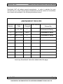
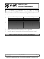
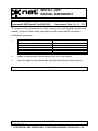
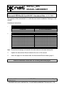
SM19
AMS42/AMS44 Series
Dual Channel Audio Controllers
INSTALLATION AND OPERATION MANUAL
REV 4.00
November 21, 2003
Northern Airborne Technology Ltd.
1925 Kirschner Road
Kelowna BC, Canada
V1Y 4N7
Telephone (250) 763-2232
Facsimile (250) 762-3374
Copyright 2003 by Northern Airborne Technology
CONFIDENTIAL AND PROPRIETARY TO NORTHERN AIRBORNE TECHNOLOGY LTD.
SM19 Rev. 4.00
AMS42/44 Dual Channel Audio Controller Manual
Periodically NAT will release manual amendments. In order to maintain the most
accurate and up to date manual these amendments should be carried out immediately
upon receipt and recorded on the following amendment record.
AMENDMENT RECORD
Amendment Amendment
Number
Date
Section(s)
Changed
Date Entered
Entered By
1
Jul 30, 2004
2
Performed at Factory
2
Feb 15, 2005
Title, 2
Performed at Factory
3
May 27, 2008
2
Performed at Factory
Insert any Amendment Instruction sheets after this page.
Nov 21, 2003
Page ii
ENG-FORM: 820-0109.DOT
CONFIDENTIAL AND PROPRIETARY TO NORTHERN AIRBORNE TECHNOLOGY LTD.
INSTALL_OPS
MANUAL AMENDMENT
Manual: SM19 (AMS42/44)
Document # SM19\Install_Ops\809-0003
Amendment #: 3
Amendment Date: May 27, 2008
The purpose of this amendment is to add the latest drawings to the manual.
Amendment Instructions:
Remove Pages
Replace With Pages
2-7 Rev 4.00 Amendment 2
2-7 Rev 4.00 Amendment 3
Remove Drawings (Section 2)
Replace or add Drawings (Section 2)
AMS44\905-1 Rev 1.02
-
AMS42\922-0 Rev 1.10
AMS44\905-0 Rev 1.03
AMS44\922-0 Rev 1.10
1
2
3
Update the Amendment Record sheet at the front of the manual.
4
Insert this page into the manual after the Amendment Record sheet (page ii).
Manual Amendment ends after the following amended pages
Amendment # 3
May 27, 2008
Page 1
ENG-FORM: 809-0109.DOT
CONFIDENTIAL AND PROPRIETARY TO NORTHERN AIRBORNE TECHNOLOGY LTD.
INSTALL_OPS
MANUAL AMENDMENT
Manual: SM19 (AMS42/44)
Document # SM19\Install_Ops\809-0002
Amendment #: 2
Amendment Date: Feb 15, 2005
The purpose of this amendment is to add a wiring note to the Cautions section of the
manual, to insert the latest wiring specifications, and to add Install Kit information.
Amendment Instructions:
Remove Pages
Replace With Pages
Title section page iii Rev 4.00
2-1 and 2-2 Rev 4.00
2-7 Rev 4.00
Title section page iii Rev 4.00 Amendment 2
2-1 and 2-2 Rev 4.00 Amendment 2
2-7 Rev 4.00 Amendment 2
1
2
Update the Amendment Record sheet at the front of the manual.
3
Insert this page into the manual after the Amendment Record sheet (page ii).
Manual Amendment ends after the following amended pages
Amendment # 2
Feb 15, 2005
Page 1
ENG-FORM: 809-0109.DOT
CONFIDENTIAL AND PROPRIETARY TO NORTHERN AIRBORNE TECHNOLOGY LTD.
INSTALL_OPS
MANUAL AMENDMENT
Manual: SM19_AMS42_AMS44
Amendment #: 1
Document # SM19\Install_Ops\809-0001 Amendment Date: Jul 30, 2004
The purpose of this amendment is to add the most recent Installation Drawings to the
manual.
Amendment Instructions:
1
2
Remove Pages
Replace With Pages
2-7 Rev 4.00
2-7 Rev 4.00 Amendment 1
Remove Drawings (Section 2)
Replace or add Drawings (Section 2)
AMS42\403-0 Rev 1.01
AMS42\403-1 Rev 1.10
AMS42\403-2 Rev 1.02
AMS42\405-0 Rev 1.00
AMS44\403-0 Rev 1.01
AMS44\403-1 Rev 1.01
AMS44\403-2 Rev 1.01
AMS44\405-0 Rev 1.01
AMS42\403-0 Rev 1.11
AMS42\403-1 Rev 1.11
AMS42\403-2 Rev 1.11
AMS42\405-0 Rev 1.01
AMS44\403-0 Rev 1.03
AMS44\403-1 Rev 1.03
AMS44\403-2 Rev 1.03
AMS44\405-0 Rev 1.02
Note: Ensure that all drawings are inserted in the order shown on the latest drawing lists.
3
Update the Amendment Record sheet at the front of the manual.
4
Insert this page into the manual after the Amendment Record sheet (page ii).
Manual Amendment ends after the following amended pages
Amendment # 1
Jul 30, 2004
Page 1
ENG-FORM: 809-0107.DOT
PROPRIETARY AND CONFIDENTIAL TO NORTHERN AIRBORNE TECHNOLOGY LTD.
SM19 Rev. 4.00
AMS42/44 Dual Channel Audio Controller Manual
Table of Contents
Section
Title
Page
1.0
Description
1.1
1.2
1.3
1.3.1
1.3.2
1.3.3
1.4
1.4.1
1.4.2
1.4.3
1.5
Introduction
Purpose of Equipment
Design Features
Transmit Functions
Receive Functions
ICS Functions
Specifications
Electrical Specifications
Physical Specifications
Environmental Specifications
Unit Nomenclature
2.0
Installation
2.1
2.2
2.3
2.4
2.4.1
2.4.2
2.4.3
2.5
2.5.1
2.5.2
2.5.3
2.5.4
2.5.5
2.6
General
Unpacking and Inspection
Continued Airworthiness
Installation Procedures
Warnings
Cautions
Cable and Wiring
Adjustments and Connections
Top panel adjustments
Right Side Adjustments
Left Side
Post-Installation Checks
Accessories Required But Not Supplied
Installation Drawings
Nov 21, 2003
ENG-FORM: 820-0109.DOT
1-1
1-1
1-1
1-1
1-2
1-2
1-2
1-2
1-3
1-3
1-4
2-1
2-1
2-1
2-1
2-1
2-2
2-2
2-2
2-3
2-4
2-5
2-6
2-6
2-7
Page iii
Amendment #2
Feb 15, 2005
CONFIDENTIAL AND PROPRIETARY TO NORTHERN AIRBORNE TECHNOLOGY LTD.
SM19 Rev. 4.00
AMS42/44 Dual Channel Audio Controller Manual
3.0
Operation
3.1
3.2
3.3
3.3.1
3.3.2
3.4
3.4.1
3.4.2
3.4.3
3.4.4
3.4.5
3.5
3.5.1
3.5.2
3.6
3.6.1
3.6.2
3.7
3.8
3.9
3.9.1
3.9.2
3.10
3.10.1
3.10.2
3.10.3
3.10.4
3.10.5
3.11
3.11.1
3.11.2
3.12
3.12.1
3.12.2
AMS42 - General Operation
AMS42 - Audio Alerting Functions
AMS42 - Selection of Transmit Functions
Transmit Selectors
Hand Microphone
AMS42 - Transceiver Receive Functions
Receive Selection Switches
Transceiver Selection Examples
Volume Controls
Passenger Receive Audio Selection
Auxiliary Inputs
AMS42 - Intercom Functions
ICS Modes of Operation
Passenger ICS Operation
AMS42 Mode Control
Emergency Operation
Isolation Operation
AMS44 - General Operation
AMS44 - Audio Alerting Functions
AMS44 - Selection of Transmit Functions
Transmit Selectors
Hand Microphone
AMS44 - Transceiver Receive Functions
Receive Selection Switches
Transceiver Selection Examples
Volume Controls
Passenger Receive Audio Selection
Auxiliary Inputs
AMS44 - Intercom Functions
ICS Modes of Operation
Passenger ICS Operation
AMS44 - Mode Control
Emergency Operation
Isolation Operation
Nov 21, 2003
3-1
3-1
3-2
3-2
3-2
3-3
3-3
3-3
3-4
3-4
3-4
3-4
3-5
3-5
3-6
3-6
3-6
3-7
3-7
3-8
3-8
3-9
3-9
3-9
3-9
3-10
3-10
3-11
3-11
3-11
3-12
3-12
3-12
3-13
Page iv
ENG-FORM: 820-0109.DOT
CONFIDENTIAL AND PROPRIETARY TO NORTHERN AIRBORNE TECHNOLOGY LTD.
SM19 Rev. 4.00
AMS42/44 Dual Channel Audio Controller Manual
Section 1.0 Description
1.1
Introduction
This manual contains information on the AMS42 and AMS44 Dual Channel Audio
Controllers.
Information in this section consists of purpose of equipment, features and specifications.
1.2
Purpose of Equipment
The AMS42 and AMS44 are dual channel audio controllers that provide central control
of all aircraft audio. They allow selection of transmit and receive audio, emergency
operation and provide LIVE, KEYED, or VOX intercom. Support for the pilot, copilot and
five passengers is provided as well as left or right side pilot configurations.
The purpose of the AMS42 and AMS44 is to provide centralized control for all audio in
the aircraft. This is accomplished by providing positions for up to five transceivers and
up to eight navaids. Other functions such as external PA interface, boom mic support
for the pilot and copilot, seven place intercom, emergency and ISO operation, two direct
audio inputs and rear hand mic operation are also provided.
1.3
Design Features
The AMS42 and AMS44 can be easily configured at the time of installation for pilot
operation from the left or right side of the controller by selection of internal jumpers and
switches accessible through the top cover. The five passenger positions are also
configurable for left or right side operation.
Both controllers provide independent volume control of S/T (sidetone), ICS (intercom)
and RX (receive) audio for left and right side users.
Both controllers utilize active bandpass filtering for RX and ICS operation for maximum
audio clarity in high ambient noise conditions.
1.3.1
Transmit Functions
Both controllers provide equal transmit capability between left and right sides and
support the use of a hand microphone. The hand mic is internally configured for left or
right side operation, and is connected directly to the selected radio for use during
emergency or equipment failure situations.
Nov 21, 2003
Page 1-1
ENG-FORM: 800-0103.DOT
CONFIDENTIAL AND PROPRIETARY TO NORTHERN AIRBORNE TECHNOLOGY LTD.
AMS42/44 Dual Channel Audio Controller Manual
SM19 Rev. 4.00
During transmit operation, the sidetone of the transceiver in use remains enabled while
all other audio, except DIRECT 2, is muted. This function is specific to each ‘side’ of the
audio controller.
Transceiver interfacing is accomplished through directly switched microphones and
ground referenced keylines. To ensure maximum radio compatibility, no diodes or other
steering components are used.
1.3.2
Receive Functions
Selecting a transceiver with the TX (transmit) rotary selector automatically selects the
associated receive audio. The RX inputs are also selected by the 3-position center-off
front panel switches, five on each side of the audio controller – the ‘up’ position selects
the respective navaid input, and the ‘down’ position selects the repective COM.
Two Direct Audio inputs are provided and are configurable for left or right side use.
1.3.3
ICS Functions
LIVE, KEYED or variable VOX ICS operation can be selected from a single control.
The AMS42 and AMS44 use dynamic noise reduction and voice band filtering to provide
the clearest possible ICS audio in high ambient noise conditions.
Transparent ICS for either the pilot or copilot allows immediate transmit operation with
no control panel switching. Return to ICS operation is automatic upon completion of the
TX operation.
Isolation and Emergency modes of operation are provided to remove the pilot(s) from
the intercom bus without interfering with normal passenger ICS.
Both controllers provide an ICS Tie line for multiple controller installations.
1.4
Specifications
1.4.1
Electrical Specifications
Input Power
Typically +22 to +32 Vdc at 250 mA
Nominal +28 Vdc
Lighting
160 mA at 28 Vdc.
600 mA at 5 Vdc.
Microphone Requirement
‘Carbon equivalent’ 250 mV into 150 Ω min.
(David Clark M1/DC, M3, M4, M7 recommended)
Page 1-2
Nov 21, 2003
ENG-FORM: 800-0103.DOT
CONFIDENTIAL AND PROPRIETARY TO NORTHERN AIRBORNE TECHNOLOGY LTD.
SM19 Rev. 4.00
AMS42/44 Dual Channel Audio Controller Manual
Receive Audio Requirement
25 mW into 600Ω
Headset Power
250 mW per channel into 600 Ω
Key Logic
Ground seeking for all lines.
‘Hard’ ground outputs to all transceivers.
TX LED on front panel lights when any transmit
key input is low except hand mic.
Cross-Talk
De-selected inputs 50 dB min. below full output
Bi-directional ICS Tie Line
340 mVrms for full output
1.6 kΩ input impedance
1.4.2
Physical Specifications
Height
1.88" (47.8 mm) max.
Length
6.77" (172.0 mm) max. from back of mounting
surface and excluding mating connectors
Width
5.75" (146.1 mm) max. front panel
5.00" (127.0 mm) max. rear enclosure
Weight
2.3 lbs (1.04 Kg)
Mounting
Standard Dzus Mounting (four fasteners)
Optional Tray Mount
1.4.3
Environmental Specifications
Temperature
-20 to +55° C (ambient)
-55 to +85° C (survival)
Altitude
25,000 feet max.
Humidity
95% Non-condensing
Shock
12g (any axis)
Vibration
Conforms to DO-160B category ‘P’
Nov 21, 2003
Page 1-3
ENG-FORM: 800-0103.DOT
CONFIDENTIAL AND PROPRIETARY TO NORTHERN AIRBORNE TECHNOLOGY LTD.
AMS42/44 Dual Channel Audio Controller Manual
1.5
SM19 Rev. 4.00
Unit Nomenclature
The AMS42/44 series are designed to be generic, fixed attribute audio controllers. For
this reason a limited number of models is available. Custom dual channel audio
controllers based on the AMS42 are renamed AA92H series and units based on the
AMS44 are renamed AA94 series.
The models available are:
AMS42
5 front panel selectable transceivers.
8 internal selectable RX inputs.
2 Direct Audio Inputs.
AMS42F
Same as AMS42 with faceplate labeling change from COM2
to AUX1 to match OAS/USFS requirements.
AMS42T
AMS42 in tray mount configuration.
AMS42FT
Combines ‘F’ and ‘T’ models.
AMS44
5 front panel selectable transceivers.
5 front panel selectable navaids.
2 internal selectable RX inputs.
2 Direct Audio Inputs.
AMS44T
AMS44 in tray mount configuration.
End of Section 1.0
Page 1-4
Nov 21, 2003
ENG-FORM: 800-0103.DOT
CONFIDENTIAL AND PROPRIETARY TO NORTHERN AIRBORNE TECHNOLOGY LTD.
AMS42/44 Dual Channel Audio Controller Manual
SM19 Rev 4.00
Section 2.0 Installation
2.1
General
Installation information in this section consists of unpacking and inspection procedures,
installation procedures, post-installation checks and installation drawings. Check all
notes and cautions before installation.
2.2
Unpacking and Inspection
Unpack the equipment carefully and locate the warranty card. Inspect the unit visually
for damage due to shipping and report all such claims immediately to the carrier
involved. Note that each complete unit should have the following:
- Warranty Card.
- Certificate of Conformity.
- AMS42 or AMS44 Dual Channel Audio Controller
- Operator’s Manual
Verify that all items are present before proceeding and report any shortage
immediately to your supplier.
Complete the warranty card information and send it to NAT when the installation is
complete. If you fail to complete the warranty card, the warranty will be subsequently
activated on the date of shipment from NAT.
2.3
Continued Airworthiness
Maintenance of the AMS42 or AMS44 Dual Channel Audio Controller is ‘on condition’
only. Periodic maintenance of this product is not required.
2.4
Installation Procedures
2.4.1
Warnings
ÍIMPORTANT!
Do not bundle any lines from this unit with transmitter coax lines. Do not bundle
any lines from this unit with 400 Hz synchro wiring, or AC power lines. Failure to
observe these limitations may result in incorrect or intermittent operation, or severe
audio interference on received and transmitted signals.
2.4.2
Cautions
In all installations, use shielded cable exactly as shown and ground as indicated.
Significant problems may result from not following these guidelines.
Nov 21, 2003
ENG-FORM: 805-0102.DOT
Page 2-1
Amendment #2
Feb 15, 2005
CONFIDENTIAL AND PROPRIETARY TO NORTHERN AIRBORNE TECHNOLOGY LTD.
SM19 Rev 4.00
AMS42/44 Dual Channel Audio Controller Manual
All audio installations can be seriously degraded by incorrect wiring and shielding, and
may result in abnormal cross-talk, hum and ground-loop noise. Be especially careful
with all microphone wiring and Tie Line wiring, as these lines carry the lowest level
signals in the aircraft.
All microphone and headset jacks should be electrically isolated from the airframe or
significant ground loop noise may result.
Failure to follow the installation and wiring instructions provided in this manual for power
and ground connections, including the rating of the circuit breaker, may lead to damage
in the power input circuitry of the unit.
2.4.3
Cable and Wiring
All unshielded wire shall be selected in accordance with AC43.13-1B Change 1,
Paragraphs 11-76 through 11-78. Wire types should be to MIL-W-22759 as specified in
AC43.13-1B Change 1, Paragraphs 11-85, 11-86, and listed in Table 11-11. For
shielded wire applications, use Tefzel MIL-C-27500 shielded wire with solder sleeves
(for shield terminations) to make the most compact and easily terminated interconnect.
Follow the wiring diagrams in Section 2.6 as required.
Allow 3" from the end of the wire to the shield termination to allow the connector hood to
be easily installed. Note that the hood is a "clamshell" hood, and is installed after the
wiring is complete. Aircraft harnessing should permit the unit to be lowered from the
panel for easy access to all side adjustments. Do NOT mount the unit until all
adjustments have been carried out.
All wiring should be at least 24 AWG, except power and ground lines, which should be
at least 20 AWG. Ensure that the ground connection is clean and well secured, and
that it shares no path with any electrically noisy aircraft accessories such as blowers,
turn and bank instruments or similar loads. Power to this unit must be supplied from a
separate breaker (1 Amp) or fuse (1 Amp fast blow), and not attached to any other
existing breaker without additional protection.
Before the unit is mounted, make all functional tests and trimpot adjustments. Be sure
the harness has enough clearance to permit the unit to be dropped down for readjustment, if needed later. Make sure that the connector locks are tightened, and the
unit is securely fastened to the panel before any flight is attempted.
2.5
Adjustments and Connections
The unit ships from the factory with all internal adjustments set to the normal test levels.
Once installed in the aircraft, it may be desirable to change some of these settings to
best suit the local operating environment. The internal adjustments are located on the
top and sides of the unit, and are as follows:
Page 2-2
ENG-FORM: 805-0102.DOT
Nov 21, 2003
Amendment #2
Feb 15, 2005
CONFIDENTIAL AND PROPRIETARY TO NORTHERN AIRBORNE TECHNOLOGY LTD.
AMS42/44 Dual Channel Audio Controller Manual
SM19 Rev 4.00
2.5.1
Top panel adjustments
2.5.1.1
Receive Selection Switches
AMS42:
The receive selection switches for the navaids are two banks of rocker
switches accessible through the top cover. The right side of the controller
responds to the switches labeled RIGHT USER RX and the left side
responds to the switches labeled LEFT USER RX. Each switch can be
individually selected or deselected by toggling the position of the switch.
To select ‘on’ press the switch downwards at the end nearest the front of
the unit (numbered 1 - 8), and to select ‘off’ press downwards at the end
nearest the back of the unit (marked OPEN.) When viewed from the front
of the unit, the switches toggle the navaids on or off from left to right as
follows:
OPEN
Switch
Function
Switch #
TAPE TAPE AUX2 AUX1
Right
Left
8
7
6
5
ADF2
ADF1
NAV2 NAV1
.
4
3
2
1
Note: These inputs are normally selected OFF (OPEN) when the unit is
shipped from the factory.
AMS44:
The receive selection switches are two pairs of rocker switches accessible
through the top cover. The right side of the controller responds to the
switches labeled RIGHT USER RX and the left side responds to the
switches labeled LEFT USER RX. TAPE R/L position is selected on or off
by these switches. Each switch can be individually selected or deselected
by toggling the position of the switch between on (pressed downwards at
the end nearest the front of the unit) and off (pressed downwards at the
end nearest the back of the unit.)
LEFT USER
RX
TAPE Right
Nov 21, 2003
TAPE Left
RIGHT USER
RX
TAPE Right TAPE Left
Page 2-3
ENG-FORM: 805-0102.DOT
CONFIDENTIAL AND PROPRIETARY TO NORTHERN AIRBORNE TECHNOLOGY LTD.
SM19 Rev 4.00
2.5.1.2
AMS42/44 Dual Channel Audio Controller Manual
DIR AUDIO Inputs
These are coupled directly to either the Right User (P) or Left User (C) of the controller
by jumpers accessible through the top cover and labeled DIR AUDIO #1 or DIR AUDIO
#2. The factory setting is for coupling to the Right User.
Coupled to
Right User
Coupled to
Left User
C
o
o
o
P o
Coupled to
Right User
o C
Coupled to
Left User
P
Couplings for DIR AUDIO #1
2.5.1.3
o
Couplings for DIR AUDIO #2
Intercom Isolation (ICS ISO)
The front panel mode switch can be used to isolate either the left (copilot) or right (pilot)
user by using the jumper labeled ICS ISO, which is accessible through the top cover. It is
normally set for isolation of the right user when the unit is shipped from the factory.
Coupled to
Left User
C
o
o
o
P
Coupled to
Right User
2.5.2
Right Side Adjustments
2.5.2.1
Sidetone (LEFT USER S/T and RIGHT USER S/T)
The Left User and Right User transmit sidetone (S/T) can be adjusted using the pots
accessible through the right side of the case. Rotating the pots clockwise increases the
sidetone, and counterclockwise reduces it.
2.5.2.2
ICS TIE LEVEL
This factory-preset pot may be covered by an adhesive disc to prevent field adjustment.
Under normal operation this pot does not need to be adjusted. Any adjustment
should be carried out by qualified personnel only!
2.5.2.3
ICS GAIN LEVEL
This factory preset pot may be covered by an adhesive disc to prevent field adjustment.
Under normal operation this pot does not need to be adjusted. Any adjustment
should be carried out by qualified personnel only!
Page 2-4
Nov 21, 2003
ENG-FORM: 805-0102.DOT
CONFIDENTIAL AND PROPRIETARY TO NORTHERN AIRBORNE TECHNOLOGY LTD.
AMS42/44 Dual Channel Audio Controller Manual
2.5.2.4
SM19 Rev 4.00
Rear Hand Mic (R MIC) and Passenger Headphones (PAX)
R MIC
l
PAX
l
Switch Positions
PAX
Left User
selected
R MIC
Right User
selected
Selection Examples
Rear Hand Mic (R MIC)
The R MIC rocker switch programs the Rear Hand Mic for functioning through the left or
right TX selector switch. The position of the switch can be toggled between Left User
(pressed downwards at the OUTBOARD end), or Right User (pressed downwards at the
INBOARD end.) It is factory pre-set to select the Left user.
Note: The TX annunciator will not light when the hand mic is used.
Passenger Headphones (PAX)
The PAX rocker switch programs the passenger headphones to the headphone audio
selected by either the Left User or the Right User. The position of the switch can be
toggled between Left User (pressed downwards at the OUTBOARD end, or Right User
(pressed downwards at the INBOARD end.) It is factory pre-set to select the Left user.
2.5.2.6
DIR #1 AUDIO LEVEL
The DIR #1 AUDIO LEVEL can be adjusted using the pot accessible through the right
side of the case.
Rotating the pot clockwise increases the sidetone, and
counterclockwise reduces it.
2.5.3
Left Side
A red LED can be seen through the aperture marked POWER ON. This illuminates to
indicate that the power supply is connected to the unit.
Nov 21, 2003
Page 2-5
ENG-FORM: 805-0102.DOT
CONFIDENTIAL AND PROPRIETARY TO NORTHERN AIRBORNE TECHNOLOGY LTD.
SM19 Rev 4.00
2.5.4
AMS42/44 Dual Channel Audio Controller Manual
Post-Installation Checks
With the controller disconnected from its mating connector, check P101 pin <17> for
+28 Vdc relative to ground, and check P101 pin <34> for continuity to ground (below 0.5
Ω). Check P102 pin <19> for the presence of the lamp dimmer voltage. Check all mic,
phone, music, and key lines for shorts to ground or adjacent pins. Check all key lines
for correct operation. Do not attach the audio controller until these conditions are
met.
Power up the aircraft's system with the unit installed and turn on the radios and
accessories required for the system. Refer to Section 3.0 for operation and set-up
information.
Start with only the pilot's headset installed. Check for correct ICS, radio, and transmit
operation. Do not proceed until the radios are functioning correctly. The S/T (sidetone)
adjustment accessible through the right side of the controller and the transceiver
internal adjustment may have to be adjusted for correct balance for the pilot and copilot.
Adjustment of the individual radio RX levels should be set first, then the front panel RX
master volume control.
Unusual buzzes, hums or other background audio are symptomatic of multiple grounds
or noisy external systems sharing the same wire bundle. Note that incorrect jack wiring
is a common fault, especially for passenger stations, and may cause loss of audio, a
tone on the headset lines, or other problems. Failure to key or correctly modulate a
transceiver may be caused by missing grounds on the radio or audio controller.
Plug in the hand mic and test for correct operation. Note that wiring faults for this
accessory may cause peculiar loss of ICS or TX functions because it has over-riding
priority in the system.
Plug in the remaining headsets and check for proper operation.
Note: an incorrect drop cord or improper jack wiring may cause a wide range of
problems from loss of audio to a tone heard in the headset.
Check levels and operation of all functions in flight to ensure proper adjustments and
settings have been made.
Page 2-6
Nov 21, 2003
ENG-FORM: 805-0102.DOT
CONFIDENTIAL AND PROPRIETARY TO NORTHERN AIRBORNE TECHNOLOGY LTD.
AMS42/44 Dual Channel Audio Controller Manual
2.5.5
SM19 Rev 4.00
Accessories Required But Not Supplied
Installation kit AA90-IKC (Alt. part No. D50S37SL-IKC) is required to complete the
installation. The kit consists of 1 50-Pin D-min Female Crimp Kit (D50SL-IKC) and 1
37-Pin D-min Female Crimp Kit (D37SL-IKC).
D50SL-IKC consists of
Quantity
1
50
1*
1*
1
Description
D-min 50 Socket Housing
MS Crimp Socket
Jack Screw Set
Lock Clip Set
50 Pin Connector Hood
NAT Part #
20-21-050
20-26-901
20-27-002
20-27-004
20-29-051
Description
D-min 37 Socket Housing
MS Crimp Socket
Jack Screw Set
Lock Clip Set
37 Pin Connector Hood
NAT Part #
20-21-037
20-26-901
20-27-002
20-27-004
20-29-038
D37SL-IKC consists of
Quantity
1
37
1*
1*
1
* Use as required.
2.6
Installation Drawings
DRAWING
REV.
DESCRIPTION
TYPE
AMS42\403-0
1.11
AMS42 Dual Channel Audio Controller
Interconnect
All
AMS42\403-1
1.11
AMS42 Dual Channel Audio Controller
Interconnect
All
AMS42\403-2
1.11
AMS42 Dual Channel Audio Controller
Interconnect
All
AMS42\405-0
1.01
AMS42 Dual Channel Audio Controller
AMS42\905-0
1.01
AMS42 Dual Channel Audio Controller
Faceplate
AMS42\922-0
1.00
AMS42 Dual Channel Audio Controller
Installation Diagram
Up to 2445
AMS42\922-0
1.10
AMS42 Dual Channel Audio Controller
Installation Diagram
2446 and up
AMS44\403-0
1.03
AMS44 Dual Channel Audio Controller
Interconnect
All
AMS44\403-1
1.03
AMS44 Dual Channel Audio Controller
Interconnect
All
AMS44\403-2
1.03
AMS44 Dual Channel Audio Controller
Interconnect
All
AMS44\405-0
1.02
AMS44 Dual Channel Audio Controller
Connector Map
All
AMS44\905-0
1.03
AMS42 Dual Channel Audio Controller
Faceplate
All
AMS44\922-0
1.00
AMS Series Dual Channel Audio Controller
Installation Diagram
Up to 2645
AMS44\922-0
1.10
AMS Series Dual Channel Audio Controller
Installation Diagram
2646 and up
SERIAL No.
AMS42
Connector Map
All
All
AMS44
Section 2.0 ends after these drawings
Nov 21, 2003
ENG-FORM: 805-0102.DOT
Page 2-7
Amendment # 3
May 27, 2008
CONFIDENTIAL AND PROPRIETARY TO NORTHERN AIRBORNE TECHNOLOGY LTD.
Confidential and Proprietary to NAT
Confidential and Proprietary to NAT
NAV1 NAV2 ADF
DME
MKR
NAV1 NAV2
ADF
DME
MKR
OFF
AMS44
OFF
COM1 COM2 FM1
FM2
AUX
FM
PTT
PA
ICS VOL
TX
AUX COM1 COM2 FM1
FM
LIVE
ISO
EMER
PA
OPER
NORM
FM2
TX
ICS VOL
Confidential and Proprietary to NAT
SM19 Rev. 4.00
AMS42/44 Dual Channel Audio Controller Manual
Section 3.0 Operation
This section is divided to provide model-specific Operational instructions.
Operation Instructions for the AMS42 can be found in Sections 3.1 to 3.6.
Operation Instructions for the AMS44 can be found in Sections 3.7 to 3.12.
3.1
AMS42 - General Operation
The AMS42 provides one central controller for all the aircraft audio, allowing selection of
transmit and receive audio, LIVE, KEYED, or VOX intercom, interface for an additional
handheld transmit microphone (hand mic), and pilot/copilot isolation/emergency
operation. Typical definition of the unit has the ‘pilot’ on the right side of the controller,
and the ‘copilot’ and passengers on the left side. This can be easily re-configured at the
time of installation for alternate seating arrangements.
Individual control over receive and transmit functions is provided for both the pilot and
copilot (observer), and a common control is provided for LIVE, KEYED and VOX ICS
operation. An additional control is provided for NORMAL, EMERGENCY, or ISOLATE
(pilot cut off from ICS audio) operation.
Sidetone (S/T) level is adjustable internally, and Receive (RX) and Intercom (ICS) levels
are adjustable on the front panel. All audio, except the S/T of the radio in use and any
Type ‘B’ DIRECT AUDIO input signals, are muted during transmit for clarity. ICS
operation allows transmit during any ICS mode by using the PTT switch.
3.2
AMS42 - Audio Alerting Functions
No internal audio alerting is provided in the AMS42. Two direct (unswitched) inputs are
provided to allow airframe alerting signals to be routed to the pilot. See Section 3.4.5
(Auxiliary Inputs) for more information.
DIR AUD #1 is amplified by the Audio controller, and can not be heard when the Mode
Switch is in the EMER position. DIR AUD #2 is not amplified, and is audible at all times.
Nov 21, 2003
Page 3-1
ENG-FORM: 806-0102.DOT
CONFIDENTIAL AND PROPRIETARY TO NORTHERN AIRBORNE TECHNOLOGY LTD.
AMS42/44 Dual Channel Audio Controller Manual
3.3
AMS42 - Selection of Transmit Functions
Transmit
Annunciator
3.3.1
SM19 Rev. 4.00
Left User (Co-pilot)
Transmit Selector
Right User (Pilot)
Transmit Selector
Transmit
Annunciator
Transmit Selectors
The transmit selector controls are six position rotary switches, one on each side of the
panel to correspond to the user on that side of the aircraft. The controls select the
transmit function required by the relevant user. Each rotary selector switch is
completely independent of the other, and the pilot and copilot have equal priority during
transmit. When the PTT is activated, all audio selected on the side of the controller that
is transmitting is muted, except the sidetone of the transceiver in use.
3.3.1.1
Automatic Receive Audio
Receive audio is automatically selected as a function of the respective rotary selector
switch. No additional switching is needed to establish external communication.
3.3.1.2
Transmit Annunciators
During transmit from either the pilot or copilot position, the appropriate TX annunciator
(green) will light on the front panel.
3.3.1.3
TX Selector Example
In the figure above, the positions of the rotary selector switches indicate that the right side
of the controller is set for transmit and receive operation on the COM2 transceiver while
the left side of the controller is set for transmit and receive operation on the FM1
transceiver.
3.3.2
Hand Microphone
The hand mic functions without power and will work in emergency or equipment failure
situations. The hand mic normally functions on the left side of the controller but can be
connected to the right side at the time of installation by changing an internal switch. When
the hand mic or transmit PTT switch is activated, the mic involved will be coupled to the
radio (or PA) selected. The TX annunciator will not light when the hand mic is used.
Page 3-2
Nov 21, 2003
ENG-FORM: 806-0102.DOT
CONFIDENTIAL AND PROPRIETARY TO NORTHERN AIRBORNE TECHNOLOGY LTD.
SM19 Rev. 4.00
AMS42/44 Dual Channel Audio Controller Manual
3.4
AMS42 - Transceiver Receive Functions
3.4.1
Receive Selection Switches
The receive audio is selected by switching any of the RX switches (white switch bats)
UP to connect the indicated radio to the headphone bus. The AUX position does not
have a separate RX switch and is connected to the headphone bus by rotating the TX
selector to the AUX position. See section 3.4.3.1 for RX volume control.
3.4.2
Transceiver Selection Examples
In the figure below, the right side TX selector is set for transmit and receive operation on
COM2. The Receive function switches are also selected so the right side can monitor
COM1 and FM2 transceivers. Note that FM1 is not selected and AUX cannot be
selected by the RX switches.
RX Switches at COM1 and FM2
TX Selector at COM2
In the figure below, the right side configuration remains the same. The left side is set up
to receive and transmit on FM1 while monitoring the COM2 transceiver. Note that
COM1 and FM2 are not selected on the left side.
RX switch at COM2
TX Selector at FM1
Nov 21, 2003
Volume Controls
(RX and ICS VOL)
Page 3-3
ENG-FORM: 806-0102.DOT
CONFIDENTIAL AND PROPRIETARY TO NORTHERN AIRBORNE TECHNOLOGY LTD.
AMS42/44 Dual Channel Audio Controller Manual
3.4.3
SM19 Rev. 4.00
Volume Controls
The controller features individual master RX and ICS VOL controls on both the left and
right sides of the unit, which can be adjusted to suit the specific user's requirements.
3.4.3.1
RX Volume Control
The RX knobs are the smaller, topmost controls of the dual concentric volume control
assemblies. The RX VOL controls provide adjustment of the RX audio selected by the
controller. As in any audio system, it is important to set the individual radio volume
controls to a nominal level that is acceptable to both pilots, then adjust the respective
master RX VOL on the audio controller to suit user preference. The RX VOL controls
are designd to provide a minimum level, even when set fully ccw.
All receive audio is muted during transmit (NORM and ISO mode).
3.4.3.2
ICS Volume Control
The ICS VOL knobs are the larger, bottom controls of the dual concentric volume
control assemblies. The ICS VOL controls provide adjustment of the ICS audio
selected by the controller. The ICS volume controls provide adjustment from 0 to full
output. See also section 3.5.
3.4.4
Passenger Receive Audio Selection
The passengers normally hear the radio audio as selected on the left side of the
controller. The passengers can be shifted to the right side by changing the setting of the
internal PAX switch, accessible through the right side of the controller. The passengers
will not hear any radio audio when the red mode switch is in the EMER position.
3.4.5
Auxiliary Inputs
Two Direct Audio inputs are available. They are coupled directly to either the left or right
side of the controller at the time of installation. The Direct Audio inputs are normally
selected for the right side of the controller when the unit is shipped from the factory.
3.5
AMS42 - Intercom Functions
All ICS audio is controlled by the front panel ICS volume controls and may be varied to
suit conditions. There are independent volume controls for the left and right sides of the
controller. The ICS VOL are the larger, aft controls of the dual concentric volume
control assemblies. See section 3.4.3.2.
If the controller is operated in the emergency mode, ICS operation will continue (if there
is no fault condition) between the passengers, but not between the pilot and copilot or
passengers.
Page 3-4
Nov 21, 2003
ENG-FORM: 806-0102.DOT
CONFIDENTIAL AND PROPRIETARY TO NORTHERN AIRBORNE TECHNOLOGY LTD.
SM19 Rev. 4.00
3.5.1
AMS42/44 Dual Channel Audio Controller Manual
ICS Modes of Operation
Intercom system (ICS) audio may be implemented in three modes between users; LIVE
(on constantly), VOX (voice activated), or KEYED (active only when switched by ICS
PTT switch). The ICS mode is selected by the ICS Mode control (see below). It is
common to use the LIVE mode during ground operations, start-up, etc., and to use VOX
or KEYED operation if conditions are so noisy that ‘pilot fatigue’ will result.
ICS Mode Control
ICS mode selection is made by positioning the ICS Mode control for the desired operation.
KEYED ICS (PTT Operation)*
ICS Mode Control set fully counter-clockwise into the switch detent.
LIVE (Hot Mic Operation)
ICS Mode Control set fully clockwise.
VOX (Voice Activated)
ICS Mode Control set fully clockwise, then slowly rotated counter-clockwise until
the intercom just becomes ‘quiet’. This setting will vary with ambient noise
conditions, and the quality and number of microphones connected in the system.
* KEYED operation is inherent to the pilot and copilot microphone circuits only.
3.5.2
Passenger ICS Operation
Passenger ICS audio is LIVE when the controller is in the LIVE or KEYED mode of ICS
operation and are VOX triggered when a VOX setting is selected. Note that the
passengers are always LIVE unless interrupted by an in-line PTT cord, or the controller
is set for VOX operation.
Passenger and copilot (observer) operations can be maximized by using PTT type cord
assemblies designed for use with NAT audio controllers.
CAUTION: Ensure that all PTT type cord assemblies have properly shielded mic and
phone wiring, or ‘crosstalk’ will occur.
Nov 21, 2003
Page 3-5
ENG-FORM: 806-0102.DOT
CONFIDENTIAL AND PROPRIETARY TO NORTHERN AIRBORNE TECHNOLOGY LTD.
AMS42/44 Dual Channel Audio Controller Manual
3.6
SM19 Rev. 4.00
AMS42 Mode Control
The Mode Control switch is a three-position, locking toggle switch that is used to select
between ISO, EMER OPER, and NORM. It is identified with a red cap.
Mode Control Switch
3.6.1
Emergency Operation
The center (EMER OPER) position of the mode switch places the controller into the
emergency operation mode. When switched to the EMER OPER position, both pilot and
copilot controls are removed from the ICS bus and connected directly to their respective
radios. This mode should be selected in the event of a box fault or power failure.
The Emergency function should be tested prior to flight to assure proper operation and
allow the radio levels to be set adequately for emergency operation.
3.6.1.1
Emergency Mode Effects
In the EMER mode, all functions are retained by the pilot and copilot, except ICS and
possibly boom mic operation. If the box or airframe fault prevents the TX annunciator
from lighting during transmit (indicating a failure in the mic keying circuit), then the hand
mic should be used. A power fault of any kind will prevent the TX annunciator from
lighting, giving an immediate indication of failure. If ICS audio is still available, then the
power to the controller has not failed and loss of the TX light indicates TX switch failure.
Note that in the EMER mode, all switches work exactly as they do during NORM operation,
except for the RX and ICS volume controls which will have no effect. Any selected receive
audio is switched to the appropriate user in the ‘emergency’ mode (red mode switch in the
EMER position), but not to any passengers in the system. Level will be lower than NORM
operation because the signals are obtained directly from the radios, bypassing the electronics in
the controller. This is provided for failure situations which make operation impossible in the
NORM mode (i.e., loss of power or amplifier failure, etc.)
3.6.2
Isolation Operation
The mode switch can select an ISO function, which prevents the selected user from
receiving ICS audio. This is useful when passengers are interfering with critical flight
operations (landing, etc.). It can be preselected at installation to isolate the left or right
side. Intercom operation for the passengers and copilot is not affected. It is normally set
for isolation of the right side when the unit is shipped from the factory.
Page 3-6
Nov 21, 2003
ENG-FORM: 806-0102.DOT
CONFIDENTIAL AND PROPRIETARY TO NORTHERN AIRBORNE TECHNOLOGY LTD.
SM19 Rev. 4.00
3.7
AMS42/44 Dual Channel Audio Controller Manual
AMS44 - General Operation
The AMS44 provides one central controller for all the aircraft audio, allowing selection of
transmit and receive audio, LIVE, PTT (Keyed), or VOX intercom, interface for an
additional handheld transmit microphone (hand mic), and pilot/copilot isolation/
emergency operation. Typical definition of the unit has the ‘pilot’ on the right side of the
controller, and the ‘copilot’ and passengers on the left side. This can be easily reconfigured at the time of installation for alternate seating arrangements.
Individual control over receive and transmit functions are provided for both the pilot and
copilot (observer), and a common control is provided for LIVE, PTT and VOX ICS
operation. An additional control is provided for NORMAL, EMERGENCY, or ISOLATE
(pilot cut off from ICS audio) operation.
Sidetone (S/T) level is adjustable internally, and Receive (RX) and Intercom (ICS) levels
are adjustable on the front panel. All audio, except the S/T of the radio IN USE and any
Type ‘B’ DIRECT AUDIO input signals, are muted during transmit for clarity. ICS
operation allows transmit during any ICS mode by using the PTT switch.
3.8
AMS44 - Audio Alerting Functions
No internal audio alerting is provided in the AMS44. Two direct (unswitched) inputs are
provided to allow airframe alerting signals to be routed to the pilot. See 3.10.5 (Auxiliary
Inputs) for more information.
DIR AUD #1 is amplified by the Audio controller, and can not be heard when the Mode
Switch is in the EMER position. DIR AUD #2 is not amplified, and is audible at all times.
Nov 21, 2003
Page 3-7
ENG-FORM: 806-0102.DOT
CONFIDENTIAL AND PROPRIETARY TO NORTHERN AIRBORNE TECHNOLOGY LTD.
AMS42/44 Dual Channel Audio Controller Manual
3.9
AMS44 - Selection of Transmit Functions
Transmit
Annunciator
3.9.1
SM19 Rev. 4.00
Left User (Co-pilot)
Transmit Selector
Right User (Pilot)
Transmit Selector
Transmit
Annunciator
Transmit Selectors
The transmit selector controls are six position rotary switches, one on each side of the
panel to correspond to the user on that side of the aircraft. The controls select the
transmit function required by the relevant user. Each rotary selector switch is
completely independent of the other, and the pilot and copilot have equal priority during
transmit. When the PTT is activated, all audio selected on the side of the controller that
is transmitting is muted, except the sidetone of the transceiver in use.
3.9.1.1
Automatic Receive Audio
Receive audio is automatically selected as a function of the respective rotary selector
switch. No additional switching is needed to establish external communication.
3.9.1.2
Transmit Annunciator
During transmit from either the pilot or copilot position, the appropriate TX annunciator
(green) will light on the front panel.
3.9.1.3
TX Selector Example
In the figure that follows, the positions of the rotary selector switches indicate that the left
and right sides of the controller are set for transmit operation on the AUX FM transceiver.
Both Transmit Selectors at AUX FM
Page 3-8
Nov 21, 2003
ENG-FORM: 806-0102.DOT
CONFIDENTIAL AND PROPRIETARY TO NORTHERN AIRBORNE TECHNOLOGY LTD.
SM19 Rev. 4.00
3.9.2
AMS42/44 Dual Channel Audio Controller Manual
Hand Microphone
The hand mic functions without power and will work in emergency or equipment failure
situations. The hand mic normally functions on the left side of the controller but can be
connected to the right side at the time of installation by changing an internal switch.
When the hand mic or transmit PTT switch is activated, the mic involved will be coupled to
the radio (or PA) selected. The TX annunciator will not light when the hand mic is used.
3.10
AMS44 - Transceiver Receive Functions
3.10.1
Receive Selection Switches
The Receive Audio select switches (white switch bats) are ‘center-off’ type with the ‘up’
position selecting the respective navaid receiver audio, and the ‘down’ position selecting
the respective transceiver audio. See section 3.10.3.1 for RX volume control.
3.10.2
Transceiver Selection Examples
In the figure below, the right TX selector is set for transmit and receive operation on the
AUX FM. The Receive function switches are also selected so the right side can monitor
COM1 and FM2 transceivers as well as NAV1 and DME navaids. Note that PA, COM2,
FM1, NAV2, ADF, and MKR are not selected.
Receive Switches at
Navaids NAV1 and DME
Receive Switches
monitor COM1 and FM2
Transmit Selector at AUX FM
Nov 21, 2003
Page 3-9
ENG-FORM: 806-0102.DOT
CONFIDENTIAL AND PROPRIETARY TO NORTHERN AIRBORNE TECHNOLOGY LTD.
AMS42/44 Dual Channel Audio Controller Manual
SM19 Rev. 4.00
In the figure below, the right side configuration remains the same. The left side is set up
to receive and transmit on COM2 while monitoring COM1 and FM2 transceivers as well
as the MKR navaid. Note that FM1, AUX FM, PA, NAV1, NAV2, ADF and DME are not
selected on the left side.
3.10.3
Receive Switches
monitor COM1 and FM2
Receive Switch
at Navaid MKR
Transmit Selector at COM2
Volume Controls
(RX and ICS VOL)
Volume Controls
The controller features individual master RX and ICS VOL controls on both the left and
right sides of the unit, which can be adjusted to suit the specific user's requirements.
3.10.3.1
RX Volume Control
The RX knobs are the smaller, topmost controls of the dual concentric volume control
assemblies. The RX VOL controls provide adjustment of the RX audio selected by the
controller from 10% to full. As in any audio system, it is important to set the individual
radio volume controls to a nominal level that is acceptable to both pilots, then adjust the
respective master RX VOL on the audio controller to suit user preference. The RX VOL
controls are designd to provide a minimum level, even when set fully ccw.
All receive audio is muted during transmit (NORM and ISO mode).
3.10.3.2
ICS Volume Control
The ICS VOL knobs are the larger, bottom controls of the dual concentric volume
control assemblies. The ICS VOL controls provide adjustment of the ICS audio
selected by the controller. The ICS volume controls provide adjustment from 0 to full
output. See also section 3.11.
3.10.4
Passenger Receive Audio Selection
The passengers normally hear the radio audio as selected on the left side of the
controller. The passengers can be shifted to the right side by changing the setting of the
internal PAX switch, accessible through the right side of the controller. The passengers
will not hear any radio audio when the red mode switch is in the EMER position.
Page 3-10
Nov 21, 2003
ENG-FORM: 806-0102.DOT
CONFIDENTIAL AND PROPRIETARY TO NORTHERN AIRBORNE TECHNOLOGY LTD.
SM19 Rev. 4.00
3.10.5
AMS42/44 Dual Channel Audio Controller Manual
Auxiliary Inputs
Two Direct Audio inputs are available. They are coupled directly to either the left or right
side of the controller at the time of installation. The Direct Audio inputs are normally
selected for the right side of the controller when the unit is shipped from the factory.
3.11
AMS44 - Intercom Functions
All ICS audio is controlled by the front panel ICS volume controls and may be varied to
suit conditions. There are independent volume controls for the left and right sides of the
controller. The ICS VOL are the larger, aft controls of the dual concentric volume
control assemblies. See also section 3.10.3.2.
If the controller is operated in the emergency mode, ICS operation will continue (if there is no
fault condition) between the passengers, but not between the pilot and copilot or passengers.
3.11.1
ICS Modes of Operation
Intercom system (ICS) audio may be implemented in three modes between users; LIVE
(on constantly), VOX (voice activated), or PTT (active only when switched by ICS PTT
switch). The ICS mode is selected by the control (labeled ICS) in the middle of the top
switch row. It is common to use the LIVE mode during ground operations, start-up, etc.,
and to use VOX or PTT operation if conditions are so noisy that ‘pilot fatigue’ will result.
ICS Mode Control
The desired ICS mode is selected by the ICS mode control knob.
PTT ICS (KEYED Operation)*
ICS Mode Control set fully counter-clockwise into the switch detent.
LIVE (Hot Mic Operation)
ICS Mode Control set fully clockwise.
VOX (Voice Activated)
ICS Mode Control set fully clockwise, then slowly rotated counter-clockwise until the
intercom just becomes ‘quiet’. This setting will vary with ambient noise conditions, and
the quality and number of microphones connected in the system.
* KEYED operation is inherent to the pilot and copilot microphone circuits only.
Nov 21, 2003
Page 3-11
ENG-FORM: 806-0102.DOT
CONFIDENTIAL AND PROPRIETARY TO NORTHERN AIRBORNE TECHNOLOGY LTD.
AMS42/44 Dual Channel Audio Controller Manual
3.11.2
SM19 Rev. 4.00
Passenger ICS Operation
Passenger ICS audio is LIVE when the controller is in the LIVE or PTT mode of ICS
operation and are VOX triggered when a VOX setting is selected. Note that the
passengers are always LIVE unless interrupted by an in-line PTT cord, or the controller
is set for VOX operation.
Passenger and copilot (observer) operations can be maximized by using PTT type cord
assemblies designed for use with NAT audio controllers.
CAUTION: Ensure that all PTT type cord assemblies have properly shielded mic and
phone wiring, or ‘crosstalk’ will occur.
3.12
AMS44 - Mode Control
Mode Control Switch
The Mode Control switch is a three-position, locking toggle switch that is used to select
between ISO, EMER OPER, and NORM. It is identified with a red cap.
3.12.1
Emergency Operation
The center (EMER OPER) position of the mode switch places the controller into the
emergency operation mode. When switched to the EMER OPER position, both pilot and
copilot controls are removed from the ICS bus and connected directly to their respective
radios. This mode should be selected in the event of a box fault or power failure.
The Emergency function should be tested prior to flight to assure proper operation and
allow the radio levels to be set adequately for emergency operation.
Page 3-12
Nov 21, 2003
ENG-FORM: 806-0102.DOT
CONFIDENTIAL AND PROPRIETARY TO NORTHERN AIRBORNE TECHNOLOGY LTD.
SM19 Rev. 4.00
3.12.1.1
AMS42/44 Dual Channel Audio Controller Manual
Emergency Mode Effects
In the EMER mode, all functions are retained by the pilot and copilot, except ICS and
possibly boom mic operation. If the box or airframe fault prevents the TX annunciator
from lighting during transmit (indicating a failure in the mic keying circuit), then the hand
mic should be used. A power fault of any kind will prevent the TX annunciator from
lighting, giving an immediate indication of failure. If ICS audio is still available, then the
power to the controller has not failed and loss of the TX light indicates TX switch failure.
Note that in the EMER mode, all switches work exactly as they do during NORM operation,
except for the RX and ICS volume controls which will have no effect.
Any selected receive audio is switched to the appropriate user in the ‘emergency’ mode (red
mode switch in the EMER position), but not to any passengers in the system. Level will be
lower than NORM operation because the signals are obtained directly from the radios,
bypassing the electronics in the controller. This is provided for failure situations which make
operation impossible in the NORM mode (i.e., loss of power or amplifier failure, etc.)
3.12.2
Isolation Operation
The mode switch can select an ISO function, which prevents the selected user from
receiving ICS audio. This is useful when passengers are interfering with critical flight
operations (landing, etc.). It can be preselected at installation to isolate the left or right
side. Intercom operation for the passengers and copilot is not affected. It is normally set for
isolation of the right side when the unit is shipped from the factory.
End of Section 3.0
Nov 21, 2003
Page 3-13
ENG-FORM: 806-0102.DOT
CONFIDENTIAL AND PROPRIETARY TO NORTHERN AIRBORNE TECHNOLOGY LTD.