1
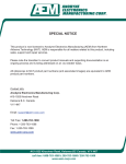
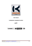
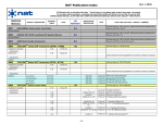
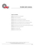
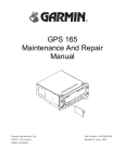
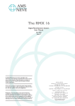
Installation and Operation Manual
AA20 Series
PA/Siren System
SM33-1
ISSUE 4.01
Northern Airborne Technology Ltd.
1925 Kirschner Road
Kelowna, BC, Canada.
V1Y 4N7
Telephone (250) 763-2232
Facsimile (250) 762-3374
Issued on the authority of Northern Airborne Technology Ltd.
Copyright 2008
AA20 Series PA/Siren System
SM33-1 Installation and Operation Manual
IMPORTANT INFORMATION
This manual has been produced to provide information unique to the AA20 Series
PA/Siren System. Some of this information has been published previously in the SM02
Service manual (AA20/22/23, PA110/220 Series Loudhailer/PA Systems).
The information presented in this manual is for reference purposes only and is intended
to provide general information that can be used by the installer/technician to gain a
fundamental understanding of the product. It is not intended to cover all variations of the
AA20 Series audio controllers. Drawing packages for specific AA20 units can be
requested from NAT by contacting the Product Support Department.
Installation and Operation Manual
ENG-FORM: 820-0114.DOT
CONFIDENTIAL AND PROPRIETARY TO NORTHERN AIRBORNE TECHNOLOGY LTD.
Page ii
AA20 Series PA/Siren System
SM33-1 Installation and Operation Manual
Prepared By:
Checked By:
Approved By:
The status of this installation and operation manual is controlled by issue shown on the title page. The
status of each section is controlled by revision shown in the footer of each page. All revisions affecting
sections of this manual have been incorporated into the latest issue.
ISSUE/REVISION RECORD
Manual Issue
Number
Section
Revision Number
Revision Description
Issue Date
4.01
Section 1 Rev: 1.00
Section 2 Rev: 1.00
Section 3 Rev: 1.00
Update to current templates.
Jun 26, 2008
Installation and Operation Manual
Page iii
ENG-FORM: 820-0114.DOT
CONFIDENTIAL AND PROPRIETARY TO NORTHERN AIRBORNE TECHNOLOGY LTD.
AA20 Series PA/Siren System
SM33-1 Installation and Operation Manual
Table of Contents
Section
Title
1.
Description
1.1
1.2
1.3
1.4
1.4.1
1.4.2
1.4.3
1.5
Introduction
Product Description
Design Features
Specifications
Electrical Specifications
Physical Specifications
Environmental Specifications
Unit Nomenclature
2.
Installation
2.1
2.2
2.2.1
2.3
2.4
2.4.1
2.4.2
2.4.3
2.4.4
2.5
2.6
2.7
Introduction
Unpacking and Inspection
Warranty
Continued Airworthiness
Installation Procedures
Warnings
Cautions
Cabling and Wiring
Post-Installation Checks
Adjustments and Connections
Accessories Required But Not Supplied
Installation Drawings
3.
Operation
3.1
3.2
3.3
3.3.1
3.3.2
3.3.3
3.3.4
3.3.5
Introduction
General Information
Controls and Indicators
Power Up
Function Switch
Volume Control
External Siren
Remote Power Switch
Installation and Operation Manual
Page
1-1
1-1
1-1
1-1
1-1
1-2
1-2
1-2
2-1
2-1
2-1
2-1
2-2
2-2
2-2
2-2
2-3
2-4
2-4
2-4
3-1
3-1
3-1
3-1
3-1
3-3
3-3
3-3
Page iv
ENG-FORM: 820-0114.DOT
CONFIDENTIAL AND PROPRIETARY TO NORTHERN AIRBORNE TECHNOLOGY LTD.
AA20 Series PA/Siren System
SM33-1 Installation and Operation Manual
Section 1 Description
1.1
Introduction
Information in this section consists of product description, design features and specifications for the AA20
Series PA/Siren System. All derivative product information shall be contained in the applicable manual
supplement, which may be obtained from NAT as required.
Review all notes, warnings and cautions.
1.2
Product Description
The AA20 PA/Siren systems are compact, self-contained systems capable of 30 W of output power.
They provide a centralized control for audio paging both inside and outside the aircraft.
The AA20 PA/Siren systems are usually used for sling load control and local external paging in smaller
airframes, or internal paging in larger airframes.
1.3
Design Features
The main functions of the AA20 include selection of audio sources for the paging audio and siren for
alerting. Microphone interfacing is accomplished from either an AA9X/AMS4X series audio controller, or a
‘carbon equivalent’ microphone. An external radio feed is provided. The internal siren is adjustable for
tone, rate and level. Provision is made for external power switching to allow PA110/220 power amplifiers
to be connected for increased power output.
All external interconnects and switches are gold plated for maximum reliability. All switches are sealed.
G10-FR flame-retardant circuit boards are post coated for maximum moisture resistance and corrosion
prevention.
1.4
Specifications
1.4.1
Electrical Specifications
Power
+22 to 32 Vdc (28 Vdc nominal) at 2.2 A max. (excluding lamps),
0.25 A idle current
Lamps
2 lamps for 28 Vdc operation @ 80 mA max load
Input
2.5 Vrms at 600 Ω (Radio and PA). Impedance 1 kΩ
Output
30 Wrms max. @ 1 kHz into 8 Ω
Microphone
Industry standard ‘carbon equivalent’ amplified dynamic
microphone preferred.
Min. 200 mV output required into 150 Ω
David Clark M1/DC, or M4 recommended
Section 1 Rev: 1.00
Issue 4
Page 1-1
ENG-FORM: 800-0113.DOT
CONFIDENTIAL AND PROPRIETARY TO NORTHERN AIRBORNE TECHNOLOGY LTD.
AA20 Series PA/Siren System
SM33-1 Installation and Operation Manual
Power Key
External switched +28 Vdc @ 250 mA max. available to activate
remote PA110/220 amplifiers
Key Logic
Ground-seeking inputs for all lines
1.4.2
Physical Specifications
Height
1.12" (28.4 mm) max.
Depth
6.56" (166.6 mm) max. (behind panel)
Width
5.76" (146.3 mm) max. (front panel)
5.01" (127.3 mm) max. (rear enclosure)
Weight
1.1 lbs (0.5 kg) (excluding mating connector)
Mounting
Standard Dzus Mounting (four fasteners)
1.4.3
1.5
Environmental Specifications
Temperature
-20 to +55°C (ambient)
Altitude
35,000 feet max.
Humidity
95% Non-condensing
Shock
12g (any axis)
Unit Nomenclature
AA20-030
Standard swept siren, adjustable rate/tone
Mode select, PA/Radio monitor
30 W output into 8 Ω
PA and Siren override at all times
Radio Monitor function
+28 Vdc switched power output
Use with PA110 and PA220 series amplifiers
AA20-050/050H
Standard swept siren, adjustable rate/tone
Mode select: Internal/External PA
30 W output into 8 Ω
PA and Siren override at all times
Radio Monitor function
Use with PA110 and PA220 series amplifiers
Adjustable internal level (-050 = 4 W, -050H = 25 W max.)
Section 1 Rev: 1.00
Issue 4
Page 1-2
ENG-FORM: 800-0113.DOT
CONFIDENTIAL AND PROPRIETARY TO NORTHERN AIRBORNE TECHNOLOGY LTD.
AA20 Series PA/Siren System
SM33-1 Installation and Operation Manual
AA20-430
3 tone chime, adjustable rate/tone
Mode select: PA/Tape
25 W output into 8 Ω
PA override at all times
Seatbelt chime interlock
Sidetone output, chime with PA key
Section 1 ends
Section 1 Rev: 1.00
Issue 4
Page 1-3
ENG-FORM: 800-0113.DOT
CONFIDENTIAL AND PROPRIETARY TO NORTHERN AIRBORNE TECHNOLOGY LTD.
AA20 Series PA/Siren System
SM33-1 Installation and Operation Manual
Section 2 Installation
2.1
Introduction
Information in this section consists of unpacking and inspection procedures, installation procedures, postinstallation checks and installation drawings for the AA20 Series PA/Siren System.
Review all notes, warnings and cautions.
2.2
Unpacking and Inspection
Unpack the equipment carefully and locate the warranty card. Inspect the unit visually for damage due to
shipping and report all such claims immediately to the carrier involved. Check that all items listed below
are present before proceeding and report any shortage immediately to your supplier:
- Warranty Card
- Operators Manual
- Certificate of Conformity or Release Certification
2.2.1
Warranty
All Northern Airborne Technology Ltd. products are warranted for 2 years from date of installation by an
authorized NAT dealer, to be free of defects in workmanship or performance. This warranty covers all
materials and labour, but is exclusive of any transport to deliver the defective unit to and from NAT or its
designated warranty repair center, or any labour to remove or re-install the defective unit in the aircraft.
Contact NAT for any questions regarding this warranty, its applicability to your units and/or for return
authorization. NAT is the final arbitrator concerning warranty administration. Units which have been
physically damaged, burned, immersed in water or otherwise abused beyond the scope of normal use will
not be considered for warranty. WARRANTY IS VOID UNLESS THE PRODUCT IS INSTALLED BY AN
AUTHORIZED NAT DEALER. Product for which a warranty card is not returned shall be warranted from
date of manufacture.
2.3
Continued Airworthiness
Maintenance of the AA20 Series PA/Siren System is ‘on condition’ only. Periodic maintenance of this
product is not required.
Section 2 Rev: 1.00
Issue 4
Page 2-1
ENG-FORM: 805-0115.DOT
CONFIDENTIAL AND PROPRIETARY TO NORTHERN AIRBORNE TECHNOLOGY LTD.
AA20 Series PA/Siren System
SM33-1 Installation and Operation Manual
2.4
Installation Procedures
2.4.1
Warnings
WARNING:
The AA20 is a high power device, capable of producing tones at very
high volume levels. Ensure that all personnel are well clear of the
aircraft prior to keying the siren or PA. Failure to adhere to this warning
could cause injury to personnel and/or damage to equipment.
2.4.2
Cautions
CAUTION:
Use shielded cable exactly as shown and ground as indicated. All audio
installations can be severely degraded by incorrect wiring and shielding.
Unusual buzzes, hums or other background audio are symptomatic of multiple
grounds, or noisy external systems such as blowers or pumps sharing wiring
with the audio system. Never operate any of these units below their
8 Ω rated impedance.
2.4.3
Cabling and Wiring
All wire shall be selected in accordance with the original aircraft manufacturer's Maintenance Instructions
or AC43.13-1B Change 1, Paragraphs 11-76 through 11-78. Unshielded wire types shall qualify to
MIL-W-22759 as specified in AC43.13-1B Change 1, Paragraphs 11-85, 11-86, and listed in Table 11-11.
For shielded wire applications, use Tefzel MIL-C-27500 shielded wire with solder sleeves (for shield
terminations) to make the most compact and easily terminated interconnect. Follow the connector map in
Section 2.7 as required.
Allow 3" from the end of the shielded wiring to the shield termination to allow the connector hood to be
easily installed. Reference the interconnect drawing in Section 2.7 for shield termination details. Note that
the hood is a "clamshell" hood, and is installed after the wiring is complete. Aircraft harnessing shall
permit the unit to be lowered from the panel for easy access to all side adjustments. Do NOT mount the
unit until all adjustments have been performed.
Maintain wire segregation and route wiring in accordance with the original aircraft manufacturers
Maintenance Instructions.
Unless otherwise noted, all wiring shall be a minimum of 22 AWG, except power and ground lines, which
shall be a minimum of 20 AWG. Reference the Interconnect drawing for additional specifications. Check
that the ground connection is clean and well secured, and that it shares no path with any electrically noisy
aircraft accessories such as blowers, turn and bank instruments or similar loads. Power to this unit must
be supplied from a separate circuit breaker or fuse (fast blow), and not attached to any other circuit
breaker without additional protection. Verify that the selected circuit breaker size and wire gauge are
adequate for the installation using the techniques specified in AC43.13-1B Change 1, Paragraphs 11-47
through 11-51 and 11-66 through 11-69.
Section 2 Rev: 1.00
Issue 4
Page 2-2
ENG-FORM: 805-0115.DOT
CONFIDENTIAL AND PROPRIETARY TO NORTHERN AIRBORNE TECHNOLOGY LTD.
AA20 Series PA/Siren System
SM33-1 Installation and Operation Manual
2.4.4
Post Installation Checks
2.4.4.1
Voltage/Resistance Checks
Do not attach the AA20 until the following conditions are met.
Check the following for all models of AA20:
a) Check P101, pins 1 and 2 for +28 Vdc relative to ground.
b) Check P101, pins 14, 15 and 16 for continuity to ground (less than 0.5 Ω).
c) Check P101, pin 3 for the presence of the lamp dimmer voltage.
d) Check P101 pins 4, 5, 6 and 7 for infinite resistance to ground (> 10 MΩ).
e) Check P101 pin 10 (AA20-030, -050, -050H) or pin 12 (AA20-430) for continuity to ground
(below 0.5 Ω). This ground is installation specific and may be a 'hard' ground or supplied by a
momentary switch (siren/chime trigger).
Check the following for AA20-030 and AA20-430:
f)
Check P101, pin 4 for continuity to pin 5 (less than 0.5 Ω).
g) Check P101, pin 6 for continuity to pin 7 (less than 0.5 Ω).
h) Check P101, pin 4 to pin 6 for 8 Ω (speaker connected).
Check the following for AA20-050 and AA20-050H:
2.4.4.2
i)
P101 pin 4 to pin 6 for 8 Ω (speaker connected) or 300 Ω (PA110/220 connected).
j)
P101 pin 5 to pin 7 for 8 Ω (speaker connected).
Power On Checks
Power up the aircraft’s systems and confirm normal operation of all functions of the AA20. Refer to
Section 3 (Operation) for specific operational details.
a) Turn on all of the radios and other accessories required for this system. Check that the
POWER ON LED on the AA20 illuminates when the power switch is selected to ON.
b) Key the siren using the front panel button and/or remote siren key. The siren should sound
and the level should be at maximum volume (the front panel level control does not affect the
siren). If the siren (rate or tone) needs adjustment use the trimpots on the left side of the
AA20. Refer to section 2.5 for details.
c) Configure the audio system as required to allow connection of the pilot's mic to the PA and
key the cyclic switch for transmit. The mic audio should be heard on the PA speakers. Adjust
the front panel level control for the desired volume.
d) Check preset adjustments are completed before aircraft departure.
Notes: 1. PA audio has priority in the AA20 system, and it will be heard even if the panel switch is
selected to RADIO. Check for correct radio operation and note the volume settings that
produce a suitable external paging level.
2. A faint audio signal may be heard at the speaker (even when the system is not paging) due to
the very high gain of this system and stray coupling in the wiring. It should not be audible in
flight.
Section 2 Rev: 1.00
Issue 4
Page 2-3
ENG-FORM: 805-0115.DOT
CONFIDENTIAL AND PROPRIETARY TO NORTHERN AIRBORNE TECHNOLOGY LTD.
AA20 Series PA/Siren System
SM33-1 Installation and Operation Manual
Upon satisfactory completion of all performance checks, make all required log book entries, electrical
load, weight and balance amendments and other documentation as required by your local regulatory
agency before releasing the aircraft for service.
2.5
Adjustments and Connections
If the siren does not suit the specific requirements of a given installation, the following adjustments are
available:
1. Base tone setting - potentiometer marked TONE
2. Sweep rate setting - potentiometer marked RATE
These controls are accessible through holes on the left side of the unit, as shown in Figure 1 below.
Siren Rate
Siren Tone
Master Level
Figure 1: Adjustments
2.6
Accessories Required But Not Supplied
Installation kit p/n AA20-IKC (crimp) is required to complete the installation. The kit consists of the
following:
Quantity
1
25
1*
1*
1
* Use as required.
2.7
Description
D-min 25 Socket Housing
MS Crimp Socket
Jack Screw Set
Lock Clip Set
25 Pin Connector Hood
NAT Part No.
20-21-025
20-26-901
20-27-002
20-27-004
20-29-026
Installation Drawings
The information presented in this manual is for reference purposes only, and is intended to provide
general information that can be used by the installer/technician to gain a fundamental understanding of
the product. It is not intended to cover all variations of the AA20 Series audio controllers. Drawing
packages for specific AA20 units can be requested from NAT by contacting the Product Support
Department.
Section 2 Rev: 1.00
Issue 4
Page 2-4
ENG-FORM: 805-0115.DOT
CONFIDENTIAL AND PROPRIETARY TO NORTHERN AIRBORNE TECHNOLOGY LTD.
AA20 Series PA/Siren System
SM33-1 Installation and Operation Manual
DOCUMENT
AA20-030
AA20\030\302-20-030A
AA20\030\403-0
AA20\030\405-0
AA20\030\905-0
AA20\030\922-0
REV.
DESCRIPTION
TYPE
1.00
1.01
1.02
1.10
1.01
PA/Siren System
PA/Siren System
PA/Siren System
PA/Siren System
PA/Siren System
Block Diagram
Interconnect
Connector Map
Faceplate
Mechanical Installation
AA20-050
AA20\050\302-20-050A
AA20\050\403-20-050A
AA20\050\405-0
AA20\050\905-0
1.00
1.00
1.01
1.10
PA/Siren System
PA/Siren System
PA/Siren System
PA/Siren System
Block Diagram
Interconnect
Connector Map
Faceplate
AA20-050H
AA20\050\302-20-050A
AA20\050\403-20-050A
AA20\050\405-0
AA20\050H\905-0
#
#
#
1.00
PA/Siren System
PA/Siren System
PA/Siren System
PA/Siren System
Block Diagram
Interconnect
Connector Map
Faceplate
AA20-430
AA20\430\302-20-430A
AA20\430\403-0
AA20\430\405-0
AA20\430\905-0
1.00
1.01
1.01
1.01
PA/Siren System
PA/Siren System
PA/Siren System
PA/Siren System
Block Diagram
Interconnect
Connector Map
Faceplate
Section 2 ends following the above documents
Section 2 Rev: 1.00
Issue 4
Page 2-5
ENG-FORM: 805-0115.DOT
CONFIDENTIAL AND PROPRIETARY TO NORTHERN AIRBORNE TECHNOLOGY LTD.
Confidential and Proprietary to NAT
Confidential and Proprietary to NAT
Confidential and Proprietary to NAT
AA20 Series PA/Siren System
SM33-1 Installation and Operation Manual
Section 3 Operation
3.1
Introduction
Information in this section consists of functional and operational procedures for the AA20 Series PA/Siren
System.
3.2
General Information
The AA20 PA/Siren System provides a central adjustment for internal and/or external aircraft paging
functions. The AA20 is a self-contained mixer/amplifier which directly drives the cabin or external
speaker(s). When turned on, the system is ready for operation and will accept audio feeds or a
microphone input. An internally generated siren is also available and adjustable through the side of the
controller. When the AA20 is turned on, a POWER KEY signal is generated. This signal is used to turn on
the PA amp (if connected in system). The high current DC power to operate the PA110/220 is supplied by
the aircraft.
3.3
Controls and Indicators
3.3.1
Power Up
To activate the AA20 PA/Siren system, flip the POWER toggle switch up to the ON position. The LED
adjacent to the switch should illuminate.
Power Switch
Indicator LED
3.3.2
Function Switch
The Function Switch is used to select the appropriate operational mode for the unit. These modes vary
depending on the unit under consideration and are listed below.
Function Switch
Note:
PA audio has priority in the AA20 system and it will be heard even if the panel switch is selected
to RADIO or TAPE.
Section 3 Rev: 1.00
Issue 4
Page 3-1
ENG-FORM: 806-0111.DOT
CONFIDENTIAL AND PROPRIETARY TO NORTHERN AIRBORNE TECHNOLOGY LTD.
AA20 Series PA/Siren System
SM33-1 Installation and Operation Manual
3.3.2.1
AA20-030
On the AA20-030, the function switch selects between PA and Radio Operation.
PA Operation
For external PA/Siren systems or internal paging functions, set the function switch on the AA20-030 to
PA. Key the microphone through the cyclic or hand mic switch and speak in a firm, clear manner.
Radio Operation
To set the system for radio rebroadcast functions, set the function switch on the AA20-030 to RADIO. All
audio delivered from the source (typically pilot’s or copilot’s headset) will be broadcast from the PA
system.
3.3.2.2
AA20-050
On the AA20-050 and AA20-050H, the function switch selects between Internal and External P/A. The
siren is disabled when the function switch is set to Internal.
Internal PA Operation
For internal PA/Siren systems or paging functions, set the function switch on the AA20-050 to INT. Key
the microphone through the cyclic or hand mic switch and speak in a firm, clear manner.
External PA Operation
For external PA/Siren systems or paging functions, set the function switch on the AA20-050 to EXT. Key
the microphone through the cyclic or hand mic switch and speak in a firm, clear manner.
3.3.2.3
AA20-430
On the AA20-430, the function switch selects between PA and Tape Operation.
PA Operation
For internal paging functions, set the function switch on the AA20-430 to PA. Key the microphone through
the cyclic or hand mic switch and speak in a firm, clear manner.
Tape Operation
To set the system for tape functions, set the function switch on the AA20-430 to TAPE. All audio delivered
from the source will be broadcast from the PA system.
Section 3 Rev: 1.00
Issue 4
Page 3-2
ENG-FORM: 806-0111.DOT
CONFIDENTIAL AND PROPRIETARY TO NORTHERN AIRBORNE TECHNOLOGY LTD.
AA20 Series PA/Siren System
SM33-1 Installation and Operation Manual
3.3.3
Volume Control
The volume level is set by the VOL pot on the front of the AA20. For external paging and rebroadcast
operations, the volume should always be set between half and full level. The setting for internal paging
must be determined by experiment to provide the desired coverage in the passenger area and to prevent
feedback.
Volume Control
3.3.4
External Siren
The external siren is operated by depressing the SIREN button on the front of the AA20, or by a remote
keying switch. The siren will sound only as long as the button is depressed.
Siren Button
If the siren does not suit the specific requirements of a given installation, the base tone, sweep rate and
siren level may be adjusted by your installer.
3.3.5
Remote Power Switch
The AA20 provides a switched 28 Vdc output that can be used to control the dc power circuit of a PA110
or PA220.
Section 3 ends
Section 3 Rev: 1.00
Issue 4
Page 3-3
ENG-FORM: 806-0111.DOT
CONFIDENTIAL AND PROPRIETARY TO NORTHERN AIRBORNE TECHNOLOGY LTD.